1
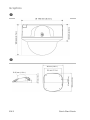
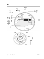
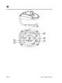
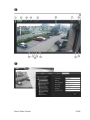
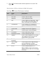
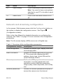
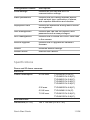
TruVision IP Dome Open-Standards Quick Start Guide P/N 1076512A-EN • REV 1.0 • ISS 07OCT11 Copyright © 2011 UTC Fire & Security. All rights reserved. Trademarks and Interlogix, TruVision brand and logo are patents trademarks of UTC Fire & Security. Other trade names used in this document may be trademarks or registered trademarks of the manufacturers or vendors of the respective products. Manufacturer UTC Fire & Security Americas Corporation, Inc. 2955 Red Hill Avenue, Costa Mesa, CA 92626-5923, USA Authorized EU manufacturing representative: UTC Fire & Security B.V. Kelvinstraat 7, 6003 DH Weert, The Netherlands FCC compliance This device complies with part 15 of the FCC Rules. Operation is subject to the following two conditions: (1) This device may not cause harmful interference, and (2) this device must accept any interference received, including interference that may cause undesired operation. Certification N4131 European Union 12004/108/EC (EMC directive): Hereby, UTC Fire directives & Security declares that this device is in compliance with the essential requirements and other relevant provisions of Directive 2004/108/EC. 2002/96/EC (WEEE directive): Products marked with this symbol cannot be disposed of as unsorted municipal waste in the European Union. For proper recycling, return this product to your local supplier upon the purchase of equivalent new equipment, or dispose of it at designated collection points. For more information see: www.recyclethis.info. Contact See www.interlogix.com or information www.utcfssecurityproducts.eu. Content Graphics 2 Introduction 6 Package contents 6 Installation environment 6 Camera dimensions 6 Setting up the camera 7 Connecting the devices 7 Accessing the camera over the internet 8 Overview of the camera Web browser 9 Network and streaming configuration 10 Specifications 11 Quick Start Guide 1 EN Graphics EN 2 Quick Start Guide Quick Start Guide 3 EN EN 4 Quick Start Guide Quick Start Guide 5 EN Introduction This pocket guide provides basic information on installing the TruVision IP dome and wedge dome open-standard cameras. For detailed information on installing and using the cameras, please refer to the user manual. Package contents The camera is shipped with the following items: Camera Hex wrench Mounting plate (excluding wedge dome cameras) Video cable for testing (excluding wedge dome cameras) Multilingual quick start guide CD with user manual in several languages Installation environment Refer to the user manual for detailed information, but observe these important requirements: • Place the camera in a secure location. • Ensure that the camera is in a well-ventilated area. • Do not expose the camera to rain or moisture. Camera dimensions See Figure (Dome and IR dome cameras) and Figure (Wedge dome cameras). EN 6 Quick Start Guide Setting up the camera Note: If the light source where the camera is installed experiences rapid, wide variations in lighting, the camera may not operate as intended. For detailed instructions, please refer to the user manual. To quickly put the camera into operation: 1. Prepare the mounting surface. 2. Connect the required cables to the camera. 3. Mount the camera to the ceiling using the appropriate fasteners. 4. Set up the camera’s network and streaming parameters so that the camera can be controlled over the network. 5. Program the camera to suit its location. Connecting the devices Dome cameras: See Figure (Connections on the base of the dome and IR dome cameras). 1. Ground. Connect to ground. 2. Ethernet RJ45 PoE port. Connect to network devices. 3. Audio output. Connect to an audio output. Line level, 600 Ω. 4. Initial set. Press to hard reboot camera. 5. Audio input. Connect to an audio input. 2.0 to 2.4 Vp-p, 1 kΩ. 6. RS-485 D+, D-. Connect to an RS-485 device such as a PTZ dome camera. 7. Alarm outputs. Connect 1A/1B and 2A/2B to alarm output devices. 8. Alarm inputs. Connect IN1/GND and IN2/GND to alarm input devices. 9. Power supply. Connect +12 VDC power supply. Quick Start Guide 7 EN Wedge dome cameras: See Figure (Wedge dome camera connections). 1. Power input connector. Connect +12 VDC power supply. Optional. 2. Ethernet RJ45 PoE connector. Connect to the network devices. 3. Lens. 4. Power LED. 5. Lens positioning screws. 6. Network status LEDs. 7. Reset switch. Click to reset all parameters to factory default. Accessing the SDHC card Insert an SDHC card up to 32GB for local storage in the dome cameras (see Figure , item ). The card is not supplied with the camera. Video and log files stored on the SDHC card can only be accessed via the Web browser. You cannot access the card using TruVision Navigator or a recording device. Note: There is no SDHC card slot in the wedge dome cameras. Accessing the camera over the internet Use the camera Web browser to access and configure the camera over the internet. Only one camera is accessible from a single Web browser window. To access the camera online: 1. In the Web browser enter the camera’s IP address (default is 192.168.1.70). The Login dialog box appears. Note: Ensure that the Active X controls are enabled. 2. Enter your user name and password. User name: admin Password: 1234 EN 8 Quick Start Guide 3. Click OK. The Web browser window appears in live mode. See Figure . Overview of the camera Web browser See Figure (Camera Web browser interface). Item Name Description 1. PTZ controls For future use. 2. Live view Click to view live video. 3. Playback Click to play back video. 4. Log Click to search for event logs. There are four main information types: All, Alarm, Notification and Operation 5. Configuration Click to display the configuration screen for setting up the camera. 6. Viewer Click to view live or play back video. 7. Current user Displays current user logged on. 8. Exit Click to log out from the system. 9. Full screen Click to view as full screen. 10. Start/stop live view Click to start/stop live view. 11. Capture Click to take a snapshot of the video. The snapshot will be saved to the default folder in jpeg format. 12. Start/stop recording Click to record live video. 13. Video image settings Click to adjust video image settings such as brightness, contrast, saturation, hue and exposure time. 14. e-PTZ Click to enable/disable e-PTZ. When enabled, scroll on the mouse wheel to zoom in and out of an image on-screen. Quick Start Guide 9 EN Item Name 15. Audio setting Description Click to start/stop bi-directional audio. Note: You need to have a microphone attached to your PC to be able to send out audio. 16. Audio on/off Click to turn the audio function on or off. Network and streaming configuration In the camera Web browser screen click the Configuration button on the toolbar to display the configuration screen. See Figure (Configuration screen). Refer to the User Manual for detailed information on configuring the cameras. See Table 1 on page 10 for an overview of the configuration parameters. Note: The On-screen display (OSD) menus are in English only. Table 1: Overview of the configuration parameters Configuration folders Description Local configuration Defines the network type, display mode and local storage paths. Basic information Defines the camera name and RS-485 bus ID. This screen also displays the MAC address, device type, device SN and the current firmware version. Channel parameters Defines the OSD properties of camera information, recording parameters and schedules, motion detection parameters, image quality, alarm responses, and overlay text. Network parameters Defines the network parameters required to access the camera over the internet. EN 10 Quick Start Guide Configuration folders Description Serial settings Defines the RS-485 and RS-232 communication settings. Alarm parameters Defines how the camera handles alarms such as input type, notification of alarms, and response schedules and duration. Deployment time Defines the schedules during which events are registered. User management Defines who can use the camera, their passwords and access privileges. HDD management Defines how to format the SDHC card used in the camera. Remote upgrade Defines how to upgrade the camera’s firmware. Default Restores default settings. Reboot device Reboots the camera. Specifications Dome and IR dome cameras: Electrical Power consumption 4.5 W max. TVD-N210V-2-N(-P), TVD-M2210V-2-N(-P), TVD-M2215V-2-N(-P), TVD-M3210V-2-N(-P), TVD-M3215V-2-N(-P) 5 W max. TVD-M5225V-4-N(-P) 5.5 W max. TVD-N245V-2-N(-P) 7.5 W max. TVD-M1210V-2-N(-P), TVD-M1225V-2-N(-P), Miscellaneous Dimensions (D × H) Quick Start Guide 140 × 120 mm (5.5 x 4.7 in.) 11 EN Weight 1.3 kg (2.8 lbs) Environmental rating Indoor vandal-resistant Wedge dome cameras: Electrical Power consumption 4 W max. Miscellaneous Dimensions (L × W × H) 100 × 98 × 47 mm (3.94 ×3.84 ×1.83 in.) Weight 0.5 kg (1.1 lbs.) Environmental rating IP66 vandal-resistant All cameras: Electrical Voltage input 12 VDC, PoE (IEEE 802.3af) I/O connection DC jack flying lead, RJ45 flying lead Network Protocols TCP/IP, HTTP, DHCP, DNS, DDNS, RTP/RTCP, PPPoE, SMTP, NTP Ethernet/IP CoS 802.1 p/Q, QoS, IPv4 PoE IEEE 802.3af Miscellaneous Operating temperature -10°C to +60°C (14 to 140°F) Storage temperature -20 to +70 °C (-4 to +158 °F) PC requirements Intel-based PC 1 GHz or faster Memory 1 GB RAM Operating system Windows® XP, Vista or Windows 7 CGI Direct X 9.0 or later Browser Microsoft Internet Explorer 6.0 or later EN 12 Quick Start Guide Quick Start Guide 13 EN EN 14 Quick Start Guide