1
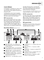
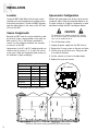
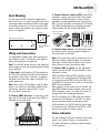
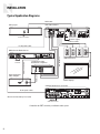
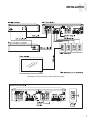
VM1 Video Matrix
HD Component Video Distribution System
Instruction Manual
SAFETY PRECAUTIONS
Important Safety Instructions
7. Wall or Ceiling Mounting - The appliance should be mounted to a
wall or ceiling only as recommended by the manufacturer.
WARNING: TO REDUCE THE RISK OF FIRE OR
ELECTRIC SHOCK, DO NOT EXPOSE THIS APPLIANCE TO RAIN OR MOISTURE.
CAUTION: TO REDUCE THE RISK OF ELECTRIC
SHOCK, DO NOT REMOVE THE COVER. NO USERSERVICEABLE PARTS INSIDE. REFER SERVICING
TO QUALIFIED SERVICE PERSONNEL.
The lightning flash with arrowhead symbol, within an equilateral triangle, is intended to alert the user to the presence of uninsulated dangerous voltage within the product’s enclosure that may be of sufficient magnitude to constitute a risk of electric shock to persons.
9. Heat - The appliance should be situated away from heat sources
such as radiators, heat registers, stoves, or other appliances
(including amplifiers) that produce heat.
10. Power Sources - The appliance should be connected to a power
supply only of the type described in the operating instructions or
as marked on the appliance.
11. Grounding or Polarization - Precaution should be taken so that
the grounding or polarization means of an appliance is not
defeated.
The exclamation point within an equilateral triangle is intended to
alert the user to the presence of important operating and maintenance (servicing) instructions in the literature accompanying the
appliance.
12. Power Cord Protection - Power supply cords should be routed
so that they are not likely to be walked on or pinched by items
placed upon or against them, paying particular attention to
cords at plugs, receptacles, and the point where they exit from
the appliance.
POWER CORD NOTICE FOR INTERNATIONAL OPERATION
13. Cleaning - The appliance should be cleaned only as recommended by the manufacturer.
For 230V, 50Hz operation, select the power cord for your area.
Select the plug for your area at one end and a IEC320 connector at
the other. It is not necessary to make any other changes. If you have
any questions, call Russound at 603-659-5170.
14. Non-Use Periods - The power cord of the appliance should be
unplugged from the outlet when left unused for a long period of
time. To remove all power (supply mains) from the appliance,
remove the plug from the wall outlet.
Safety Instructions
15. Object and Liquid Entry - Care should be taken so that objects
do not fall and liquids are not spilled into the enclosure through
the openings.
1. Read Instructions - All the safety and operating instructions
should be read before the appliance is operated.
2. Retain Instructions - The safety and operating instructions should
be retained for future reference.
16. Damage Requiring Service - The appliance should be serviced by
qualified service personnel when:
A. The power supply cord or the plug has been damaged; or
3. Heed Warnings - All warnings on the appliance in the operating
instructions should be adhered to.
B. Objects have fallen, liquid has been spilled into the appliance;
or
4. Follow Instructions - All operating and user instructions should
be followed.
C. The appliance has been exposed to rain; or
5. Water and Moisture - The appliance should not be used near
water; for example, near a bathtub, washbowl, kitchen sink, laundry tub, in a wet basement, or near a swimming pool. The apparatus shall not be exposed to dripping or splashing liquids and
no objects filled with liquids, such as vases, shall be placed on
the apparatus.
E. The appliance has been dropped or the enclosure is damaged.
6. Carts and Stands - The appliance should
be used only with a cart or stand that is
recommended by the manufacturer. An
appliance and cart combination should be
moved with care. Quick stops, excessive
force and uneven surfaces may cause the
appliance and cart combination to overturn.
2
8. Ventilation - The appliance should be situated so that its location
or position does not interfere with its proper ventilation. For
example, the appliance should not be situated on a bed, sofa,
rug, or similar surface that may block the ventilation openings,
or placed in a built-in installation, such as a bookcase or cabinet
that may impede the flow of air through the ventilation openings.
D. The appliance does not appear to operate normally; or
17. Servicing - The user should not attempt to service the appliance
beyond that described in the operating instructions. All other
servicing should be referred to qualified service personnel.
TABLE OF CONTENTS
INTRODUCTION
Product Overview. . . . . . . . . . . . . . . . . . . . . . . . . . . . . . . . . 4
Control Methods . . . . . . . . . . . . . . . . . . . . . . . . . . . . . . . . . 5
Rear-Panel Features . . . . . . . . . . . . . . . . . . . . . . . . . . . . . . . 5
INSTALLATION
Location . . . . . . . . . . . . . . . . . . . . . . . . . . . . . . . . . . . . . . . 6
Source Assignments . . . . . . . . . . . . . . . . . . . . . . . . . . . . . . 6
Upconverter Configuration . . . . . . . . . . . . . . . . . . . . . . . . . . 6
Rack Mounting . . . . . . . . . . . . . . . . . . . . . . . . . . . . . . . . . . . 7
Wiring and Connections . . . . . . . . . . . . . . . . . . . . . . . . . . . . 7
Status Indication . . . . . . . . . . . . . . . . . . . . . . . . . . . . . . . . . 7
Typical Application Diagrams . . . . . . . . . . . . . . . . . . . . . . . . 8
REFERENCE
Technical Specifications . . . . . . . . . . . . . . . . . . . . . . . . . . . 10
Warranty . . . . . . . . . . . . . . . . . . . . . . . . . . . . . . . . . . . . . . 11
3
INTRODUCTION
Product Overview
The VM1 Video Matrix works with a multiroom audio
system to distribute analog component video over a
single CAT-5e cable to each zone. Capable of handling high-definition component video signals, it also
provides conversion of composite and S-video signals
in some configurations.
Designed for use with Russound RNET® multiroom
solutions, the VM1 provides seamless integration with
the Russound CAA, CAM, and CAV systems.
The VM1 also works with other systems through serial control and offers three control options:
• RNET via RJ-45 modular ports
• RS-232 via DB9 port
• PC control via USB port
The Video Matrix is not IR controllable.
The VM1 has a rack-mountable 2U chassis and
includes the following:
• 24 VDC power supply
• Rear-panel power switch
• Front-panel multifunction LED power and control
data traffic indicators
• Removable rack ears
A red LED on the front panel indicates the power
state of the VM1. It glows steadily to indicate power
on and blinks to indicate an error in powering up.
A green LED blinks to indicate control data traffic on
the serial bus.
VM1 Configurations
The Video Matrix is available in five configurations:
VM1 4 – Provides basic 4x4 switching from analog
component video sources only.
VM1 4UC – Provides 4x4 component video switching
with one upconverter.
VM1 8 – Provides basic 8x8 switching from analog
component video sources only.
VM1 8UC – Provides 8x8 component video switching
with one upconverter.
VM1 8UC2 – Provides 8x8 component video switching with two upconverters.
4
The 4x4 configurations provide four source inputs and
four zone outputs. The 8x8 configurations provide
eight source inputs and eight zone outputs.
Each source input has red, green, and blue RCA connectors for component video signals. Each zone output has an RJ-45 8-pole modular connector for a CAT5e cable, which feeds an in-wall VMR1 receiver at the
zone’s display location.
The upconverter (UC and UC2) configurations convert
S-video and composite video signals to component
video for distribution while maintaining the original
source resolution. The benefit is that the user doesn’t
have to select a composite or S-video input on the
display to view the sources.
The UC configurations of the Video Matrix provide
conversion for sources 1 and 4. The UC2 configuration provides conversion for sources 1, 4, 5, and 8.
All upconverter configurations provide mini-DIN connectors for S-video signals and RCA connectors for
composite video signals. Internal switches allow the
installer to select which inputs are used, whether
composite, S-video, or component.
VMR1 Receiver
The VMR1 Receiver is a single-gang in-wall device
that installs in each room where component video
distribution is desired. It receives the video signal
from the VM1 through a single CAT-5e cable and provides red, green, and blue RCA jacks for direct connection to the display with an RGB video cable.
Video Resolution
The Video Matrix system is capable of high-definition
resolution up to 1080p. However, the signal resolution of the HD sources must be compatible with the
connected displays. Thus, if any display connected to
the Video Matrix is limited to 480p, that output resolution must be selected on each connected source,
unless the display has the ability to scale the image
down from a higher resolution. Otherwise the image
will not display properly.
INTRODUCTION
Control Methods
The Video Matrix is controlled by the system to which
it is connected. It switches video sources to the
zones by receiving source selection commands from
the the host system.
The VM1 provides a choice of ports for receiving
control data from the host system: two RJ-45 jacks
for linking to a Russound RNET multiroom system; a
DB9 serial connector; and a USB connector.
RNET communication
When connected through the RNET port, the Video
Matrix monitors the RNET system’s communication
bus and responds to source selection events for
sources 1 through 6 from zones 1 through 8. (In a
system with multiple six-zone controllers, zones 7
and 8 are zones 1 and 2 on controller 2.) With the
CAV6.6 system, it also responds to selection of the
Rear-Panel Features
1
2
6
The 4x4 configurations of the VM1 respond to source
selection commands for sources 1 through 4 only.
RS-232 communication
The DB9 serial port allows control of the Video Matrix
from a home automation and control system such as
AMX or Crestron. In this application, the VM1 uses
RS-232 command strings for source selection. The
RS-232 command protocol for the VM1 is available
from the Document Center at www.russound.com.
USB communication
The USB port is for control devices that do not have
DB9 legacy connections. It uses the same RS-232
command strings as the DB9 port.
(VM1 8UC2 shown)
3
4
7
8
1
RNET PORTS (RJ-45) – For connection to an
RNET multiroom system for synchronized audio
and video switching
2
RS-232 INTERFACE (DB9) – For serial control of
the Video Matrix from a separate control system
3
USB PORT (Type B) – For serial control of the
Video Matrix from a computer or control system
4
UPCONVERTER SOURCE INPUTS – Connections
for S-video and composite video sources on the
optional upconverter modules
5
Front (Aux) A/V Input (source 7). This permits the
Video Matrix to distribute that source instead of running a separate video cable from the source to the
display and selecting it at the display.
5
9
10
6
SOURCE INPUTS 1–4 – Component video source
connections
7
ZONE OUTPUTS 1–4 – Connections for VMR1
receivers
8
POWER INPUT – Connection for included 24 VDC
power supply
9
SOURCE INPUTS 5–8 – Component video source
connections on 8x8 configurations
10 ZONE OUTPUTS 5–8 – Connections for VMR1
receivers on 8x8 configurations
POWER SWITCH – Turns Video Matrix on and off
5
INSTALLATION
Location
Upconverter Configuration
Locate the VM1 Video Matrix with the host system
controller and source equipment to facilitate source
and control connections. Locate the VMR1 Receivers
near the video displays in the zones, within 300 feet
(90 m) of the VM1.
Models with upconverters are factory set to convert
composite video. Follow the procedure below to set
the input switches to S-video or Component as needed before installing the VM1 (see diagram below).
CAUTION
Source Assignments
Because the VM1 tracks the source selections made
by the host system, source numbers must match on
both systems. Thus, a DVD player connected to
source 2 on the multiroom controller also connects
to source 2 on the VM1.
Upconverters in the UC and UC2 models provide connections only for sources 1, 4, 5, and 8. Be sure to
assign your S-video and composite video sources on
the multiroom system accordingly.
This procedure is for qualified personnel only. To reduce
the risk of electric shock, do not perform this procedure
unless you are qualified to do so.
1. Turn off the power switch.
2. Unplug the power supply from the VM1 chassis.
3. Remove the 9 cover screws on the rear and sides.
4. Pull the cover up off the chassis, lifting one side
first and then the other.
5. Set the switches as shown in the table below.
6. Replace the cover and screws.
Upconverter Switches (0 = Off, 1 = On)
Input 1 or 5
1
2
Component
NA
0
Composite
1
1
S-video
0
1
Input 4 or 8
3
4
Component
NA
0
Composite
1
1
S-video
0
1
DIP switches
Upconverter input DIP switch settings
Top view of VM1 interior showing upconverter input switch locations
6
INSTALLATION
Rack Mounting
To rack mount the VM1, attach the supplied rack
ears to the chassis as shown. Leave one rack unit of
space open above and below the VM1 to allow proper ventilation of the chassis. Do not mount the VM1
above a device that produces high amounts of heat,
such as an amplifier.
Rack ear
3. Connect Receiver cables to VM1. Crimp RJ-45
connectors on the system end of the CAT-5e cables,
following the T568A standard as shown. Plug the
connectors into the appropriate zone outputs on the
VM1. (If using wall plates, punch down the CAT-5e per
the T568A standard and use straight-through patch
cables between the VM1 and the wall plates.)
RJ-45 Using T568A
Wiring Standard
+
+
+
VM1 Chassis side view
Rack mounting
flange
Wiring and Connections
The Video Matrix handles all the video switching for
the multiroom system. The following steps apply to
wiring and connections for video only.
Note: Turn the VM1 power switch off and unplug the
power supply from the wall receptacle before making
any connections.
1. Run cable. Install lengths of CAT-5e cable up to
300 feet (90 m) between the VM1 and the video display locations in the zones. If desired, use modular
wall plates and RJ-45 patch cables at the VM1 for a
neater appearance.
Note: When running CAT-5e cables, avoid AC power
wiring. If you have to run the cables parallel to electrical wiring, space the cable at least 12 inches
(30 cm) from AC power lines.
2. Connect VMR1 Receivers. In each zone, punch
down the CAT-5e cable on the back of the VMR1 as
indicated on the circuit board.
4. Connect video sources. Use video patch cables
to connect from the source component outputs to
the source inputs on the VM1.
Note: Each source input with an upconverter can use
either the S-video, composite video, or component
video input. Set the internal switches to the correct
format for each source (see previous page).
5. Connect VM1 to system. Use the appropriate
cable to connect the VM1 to the multiroom or home
automation system.
RNET connection: With the RNET multiroom system
turned off, use a straight-through RJ-45 patch cable
to connect from either RNET port on the VM1 to any
unused RNET Link port on the system or a connected
RNET source component.
When powering up the system, turn on the VM1 and
other RNET peripheral devices before turning on the
RNET multiroom system. This allows the system to
recognize the VM1 and peripheral devices.
RS-232 connection: Use a DB9 serial data cable to
connect from the DB9 port on the VM1 to a similar
port on the home control or automation system.
USB connection: Use a USB Type B to Type A cable
to connect from the USB port on the VM1 to a USB
port on the computer or control system.
Status Indication
The red front-panel LED glows steadily to indicate the
power is on. It blinks if there is a power-up error.
CAT-5e cable connection on rear of VMR1
The green LED blinks to indicate control data traffic
on the serial bus.
7
INSTALLATION
Typical Application Diagrams
RGB cable
DVD player*
VM1 Video Matrix
Audio to controller
Power supply
CAT-5e cables
RJ-45 patch cable
RGB cable
VGA-component
video adapter*
VGA IN
VMR1 Receivers
RGB cable
Component video
distribution amplifier*
VGA serial cable
Audio to
controller
RGB cables
SMS3 Smart Media Server
Video display*
CAM6.6T Multiroom Controller
RJ-45 patch cable
CAM6.6
*Not manufactured by Russound
Audio from sources
Connection for RNET control by a multiroom audio system
8
INSTALLATION
Connection for RS-232 control by a home automation system
9
REFERENCE
Technical Specifications
VM1 Video Matrix
Component video connectors:
Zone output connectors:
System cable:
Maximum cable length:
Video resolution:
Communication ports:
3 RCA per input (RGB)
8-pole modular RJ-45
CAT-5e
300 ft (90 m)
Up to 1080p
2 RJ-45 RNET Link
1 DB9 RS-232
1 USB 1.1
Power requirement: 24 VDC 2.5 A
(adapter included)
Chassis dimensions: 17” W x 3.43” H x 13.15” D
(43.0 x 8.7 x 3.34 cm)
Weight: 11.65 lb (5.28 kg)
VM1 4
Component video inputs: 4
Zone outputs: 4
VM1 8
Component video inputs: 8
Zone outputs: 8
VM1 8UC
Component video inputs: 8
S-video inputs: 2 mini-DIN
(sources 1 and 4)
Composite video inputs: 2 RCA
(sources 1 and 4)
Zone outputs: 8
VM1 8UC2
Component video inputs: 8
S-video inputs: 4 mini-DIN
(sources 1, 4, 5, and 8)
Composite video inputs: 4 RCA
(sources 1, 4, 5, and 8)
Zone outputs: 8
VM1 4UC
Component video inputs: 4
S-video inputs: 2 mini-DIN
(sources 1 and 4)
Composite video inputs: 2 RCA
(sources 1 and 4)
Zone outputs: 4
10
VMR1 Video Matrix Receiver
Single-gang in-wall Decora®
110 punch-down block
3 RCA (RGB)
1.75” W x 4.17” H x 1.31” D
(4.4 x 10.6 x 3.3 cm)
Weight: 2.2 oz (61.3 g)
Device type:
Input connector:
Output connectors:
Dimensions:
REFERENCE
Warranty
The Russound VM1 Video Matrix is fully guaranteed against all defects in materials and workmanship for two (2) years from the
date of purchase. During this period, Russound will replace any defective parts and correct any defect in workmanship without
charge for either parts or labor.
For this warranty to apply, the product must be installed and used according to its written instructions. This warranty does not
cover: damage caused by abuse, misuse, negligence, or improper installation or operation; damage from power surges or lightning strikes; normal wear; accidental or shipping damage; products that have been altered or modified; any product whose
serial number or other identification has been altered, defaced or removed.
Damage to or destruction of components from applying incorrect or excessive power voids the warranty. In such cases, repairs
will be made at the owner’s expense.
If service is necessary, it must be performed by Russound. Russound assumes no responsibility for service performed by an
agency or person not specifically authorized in writing by Russound.
To obtain repair service, the product must be returned to Russound at the owner’s expense and with prior permission. Before
returning a product for repair, call Russound at 603.659.5170 for a Return Authorization (RA) number. Pack the product in a
sturdy corrugated container with at least 3 inches (7.5 cm) of resilient material to protect it from damage in transit. Write the
RA number on the shipping label and ship the package prepaid to: Russound, 5 Forbes Road, Newmarket NH 03857.
Russound sells products only through authorized dealers and distributors to ensure that customers obtain proper support and
service. Any Russound product purchased from an unauthorized dealer or other source, including mail order sellers and online
sellers, will not be serviced under warranty. Any unauthorized sale of a Russound product voids the product warranty.
11
VM1 Video Matrix
Component Video Distribution System
Instruction Manual
Models
VM1 4
VM1 4UC
VM1 8
VM1 8UC
VM1 8UC2
Russound
5 Forbes Road, Newmarket NH 03857 USA
Tel 603.659.5170 • Fax 603.659.5388
www.russound.com
Technical Support: [email protected]
28-1235 05/03/07
Copyright © 2007 Russound. All rights reserved. All trademarks are the property of their respective owners. Specifications are
subject to change without notice. Russound is not responsible for typographical errors or omissions.