1
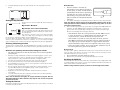
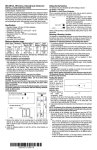
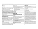
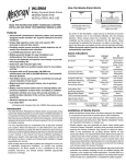
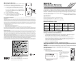
Mounting the Detector
Once you have found a location that is within range of
the receiver, you can mount the WLS912L.
1.
Remove the mounting plate from the detector.
2.
At the selected mounting location, place the
mounting plate on the wall (with the tab facing
down, or to the right), or on the ceiling. Mark the
screw locations. Wall anchors should be used for
all screw locations.
Secure the backplate to the wall.
Slide the detector onto its backplate.
Repeat the installation test using the AFT–100
tester to confirm proper operation.
3.
4.
5.
FCC Compliance Statement
CAUTION: Changes or modifications not expressly approved by Digital Security Controls Ltd. could void your authority to use
this equipment.
This equipment generates and uses radio frequency energy and if not installed and used properly, in strict accordance with the
manufacturer’s instructions, may cause interference to radio and television reception. It has been type tested and found to comply
with the limits for Class B device in accordance with the specifications in Subpart “B” of Part 15 of FCC Rules, which are designed
to provide reasonable protection against such interference in any residential installation. However, there is no guarantee that interference will not occur in a particular installation. If this equipment does cause interference to television or radio reception, which
can be determined by turning the equipment off and on, the user is encouraged to try to correct the interference by one or more
of the following measures:
• Re-orient the receiving antenna
• Relocate the alarm control with respect to the receiver
• Move the alarm control away from the receiver
• Connect the alarm control into a different outlet so that alarm control and receiver are on different circuits.
If necessary, the user should consult the dealer or an experienced radio/television technician for additional suggestions. The user
may find the following booklet prepared by the FCC helpful: “How to Identify and Resolve Radio/Television Interference Problems”. This booklet is available from the U.S. Government Printing Office, Washington, D.C. 20402, Stock # 004-000-00345-4.
WLS912L
Glassbreak Detector
Available Models: WLS912L-433, WLS912L-900
Installation Instructions
The WLS912L is a battery-operated glassbreak sensor, designed to detect the sound
produced by the shattering of framed glass. Equipped with an RF transmitter, the
WLS912L establishes a supervised, one–way communications link with the system
controller. The WLS912L uses Dynamic Signal Processing* to provide accurate
detection of plate, laminated, wired and tempered glass types, while rejecting common false alarm sounds.
*Protected under US Patent 5,675,320
Specifications
Operating Voltage: 3.0V (two 3V Lithium batteries)
Operating Temperature: 0oC - 50oC (32o F - 122oF)
Operating Humidity: 5% – 95% RH, non-condensing
Maximum detection range
Glass Type
Thickness
Minimum Glass
Size (L X W)
Level 1
Setting
Level 2
Setting
Plate/
Tempered
1/8" – 1/4"
3 – 6mm
12" X 12"
30cm X 30cm
20ft
6m
10ft
3m
Wired/
Laminated
1/4"
6mm
18"X18"
46cmX46cm
20ft
6m
DO NOT USE
Limited Warranty
Digital Security Controls Ltd. warrants that for a period of twelve months from the date of purchase, the product shall be free of defects
in material and workmanship under normal use and that in fulfilment of any breach of such warranty, Digital Security Controls Ltd.
shall, at its option, repair or replace the defective equipment upon return of the equipment to its repair depot. This warranty applies
only to defects in parts and workmanship and not to damage incurred in shipping or handling, or damage due to causes beyond control
of Digital Security Controls Ltd. such as lightning, excessive voltage, mechanical shock, water damage, or damage arising out of abuse,
alteration or improper application of the equipment.
The foregoing warranty shall apply only to the original buyer, and is and shall be in lieu of any and all other warranties, whether express
or implied and of all other obligations or liabilities on the part of Digital Security Controls Ltd. This warranty contains the entire warranty. Digital Security Controls Ltd. neither assumes responsibility for, nor authorizes any other person purporting to act on its behalf
to modify or to change this warranty, nor to assume for it any other warranty or liability concerning this product.
In no event shall Digital Security Controls Ltd. be liable for any direct, indirect or consequential damages, loss of anticipated profits,
loss of time or any other losses incurred by the buyer in connection with the purchase, installation or operation or failure of this product.
©2002 Digital Security Controls Ltd.
Toronto, Canada • www.dsc.com
Technical Help Desk (Canada & US): 1-800-387-3630
Printed in Canada 29005723 R005
Compatible control units/receivers: (P)NT9010-433, P(C)5132-433 or Envoy
Battery Guidelines and Installation
•
Use fresh batteries. Most batteries have a “best before” date printed on their
packaging or on the batteries themselves. Buy batteries that have a “best
before” date of two years or more from your purchase date
•
When disposing of used batteries, follow the instructions and precautions
printed on the batteries. Many cities and communities have collection sites or
services for used household batteries. Contact your municipal offices for
information on the disposal of used batteries
•
Do not mix old and new batteries
•
Dispose of any batteries promptly, keep away from children
NOTE: Use only Energizer Lithium EL123AP, Tekcell CR123A or Panasonic
CR123A lithium batteries. Use of any other battery may present a risk of fire or
explosion.
CAUTION: The cell used in this device may cause a fire or chemical burn hazard if
mistreated. Do not recharge, disassemble, heat above 100°C
(212°F) or incinerate.
To install batteries:
1. Remove the detector from its mounting plate:
If unmounted, hold the detector by its sides and push down on
the top end of the mounting plate, as shown at
right.
If mounted, press the
detector in the direction
shown below.
2.
Install the batteries positive (+) side first, with the correct polarity, as shown
below.
Setting the Dip Switches
The detector has user-selectable dip switch settings as
shown.
Dip Switch 1– Not Used
Dip Switch 2– Level 1/Level 2 Detection
This is a sensitivity selection dip switch which may be
used to optimize false alarm immunity for certain acoustic environments.
The detector is factory set for Level 1 detection (Dip
Switch 2 = OFF). This is the highest sensitivity setting
for the detector, and will be suitable for most applications.
For rooms which are smaller, and contain a significant number of sound-reflective
surfaces (such as bathrooms, kitchens, entrances, etc.), Level 2 detection (Dip
Switch 2=ON) provides a reduced sensitivity setting which may be more appropriate.
Detection Test:
1. Place the detector in test mode by
momentarily pressing down on the tab on
the base plate, as shown. The LED will blink
periodically to indicate that it is operating in
test mode. You can end the test mode by
momentarily pressing the tab on the base
plate. Test mode will end automatically after
10 minutes.
2. Use double-sided tape to temporarily mount the detector in the selected location
Note: The detector will not respond to the glassbreak simulator unless the test
mode operation has been enabled by momentarily pressing down on the test
mode tab on the base plate.
3. At the window to be protected, test the detector using the AFT–100 Glassbreak
Simulator. The AFT–100 Glassbreak Simulator generates plate or tempered
glass sounds. Use the plate glass setting if you are unsure of the glass type.
Observe the following when testing the detector:
• If the WLS912L detects the sound generated by the AFT-100 three times
in a row, the detector is in a good location. If the detector does not
respond each time, relocate the detector and repeat the test.
• If the windows in question are covered by drapes or blinds, place the
AFT-100 tester behind the closed window coverings, and then activate it.
If the drapes prevent reliable detection, we suggest that the detector be
mounted behind the drapes either on an adjacent wall or on the ceiling.
• If there are multiple windows, or one large window, activate the tester at
the furthest point on the glass from the detector.
Selecting a Mounting Location
The detector is omnidirectional, providing 360 degree coverage. Coverage is measured from the center of the detector to the point on the glass farthest from the detector.
Guidelines for optimizing detection and avoiding false alarms
• For optimum protection, the detector should have a direct line of sight to the
protected glass.
•
Window coverings will absorb sound from the shattering glass. In these cases,
mount the detector as close as possible to the protected glass, either on an
adjacent wall, the ceiling, or behind the window covering if possible.
•
The detector should be mounted at least 1.8m (6 feet) off the ground.
•
Do not mount the detector on the same wall as the protected glass.
•
Avoid installation near noise sources, such as speakers or other objects which
produce sounds continuously.
•
Do not install the detector beyond the maximum recommended range, even if
the AFT–100 simulator shows additional range - future changes in room
acoustics could reduce the range.
•
Application on 24 hour loops should be avoided unless the location is
unoccupied.
•
Test false alarm immunity by creating any sounds in the room which will likely
occur when the alarm system is armed.
Note: Test the detector thoroughly for proper placement using the AFT-100
Glassbreak Simulator. Other simulators may trip the unit, but will not provide
accurate test results.
Testing the detector
Perform the following tests with each WLS912L detector to ensure that it is mounted
in the best possible location.
Receiver Test:
You also need to perform a Module Placement Test to ensure that the selected location is in range of the wireless receiver (see the Placement Test instructions in the
installation instructions for your receiver).
1.
Press and hold the test mode tab for 5 seconds
2.
Release the test mode tab. The keypad will display the test result.
Enrolling the WLS912L
On the back of the detector, there will be two serial numbers: a five-digit number and
a six-digit number. Please refer to your receiver installation manual for information on
which serial number should be enrolled.
NOTE: If using a WLS900 system, you must use the five-digit serial number.