1
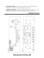
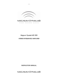
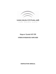
-1-
Magnum Dynalab MD 208
DISCRETE AUDIO RECEIVER
INSTRUCTION MANUAL
-2-
TABLE OF CONTENTS
DEAR VALUED CUSTOMER ...........................................................................3
UNPACKING YOUR MD 208..........................................................................4
SETTING UP THE MD 208 ............................................................................5
SET UP OF THE INTEGRATED AMPLIFIER SECTION OF THE MD 208........................................... 6
SET UP OF THE TUNER SECTION OF THE MD 208 .................................................................. 6
CONNECTING ADDITIONAL SOURCES TO THE MD 208 ............................................................ 7
SET UP THE MD 208 WITH AN EXTERNAL HOME THEATER PROCESSOR................................... 7
HOOKING UP A SUBWOOFER TO YOUR SYSTEM .................................................................... 8
TAPE OUT LOOP ............................................................................................................... 8
RC8 REMOTE CONTROL ...............................................................................9
FUNCTIONS OF THE RC8 REMOTE ....................................................................................... 9
IMAGE OF RC8 REMOTE................................................................................................... 10
CONTROL FUNCTIONS................................................................................11
DISPLAY FUNCTIONS .................................................................................11
DIAGRAM OF MD 208 ...............................................................................12
TROUBLE SHOOTING..................................................................................13
RECEPTION TECHNIQUES............................................................................14
FM RECEPTION AIDS AND ACCESSORIES.......................................................15
SAFETY SHEET..........................................................................................16
LIMITED WARRANTY .................................................................................17
-3-
Dear Valued Customer
Thank you for choosing the Magnum Dynalab “MD 208” Discrete Audio Receiver.
Great care has been given to the design, manufacturing and selection of
components for the “MD 208” Discrete Audio Receiver. This complete process
insures optimum listening enjoyment for many years.
The FM Section is a special design completely researched and manufacturer in
house. In fact, we are the only company in the world that does their own R.F. front
end, choosing this practice due to the fact that no other manufacturer can produce
one that meets our very rigid performance specifications. These rigid specifications
insure that you can enjoy excellent FM reception regardless of signal conditions.
The Integrated Amplifier section of the MD 208 is characterized by the simplicity of
the circuit. We use only high grade components, ensuring that accuracy and
realism of the music is the end result. The power supply with its specially designed
transformer is at the heart of the stability and dynamics that the MD 208 exhibits.
When using these high grade components, a considerable length of time is required
for the MD 208 to reach its full potential. Using either a high quality break-in disc or
white noise from a FM tuner will help ensure optimum performance as quickly as
possible.
Once again, thank you for including a MAGNUM DYNALAB product in your
entertainment system. We are sure that you will have years of listening pleasure
from your MD 208. Please be sure to register your product at
www.magnumdynalab.com, and if there is anything else we can do, please call us on
our toll free number, 1-800-551-4130, or contact us via email:
[email protected].
Respectfully yours,
Larry Zurowski
President
-4-
UNPACKING YOUR MD 208
Carefully inspect all sides of the shipping carton for damage. If there are marks or
holes in the carton make note of the location in relation to the unit inside. Any
obvious dents or scuff marks should alert you to the possibility of damage. Carefully
remove the MD 208 from the end caps and wrapping, inspect all sides. Pay special
attention to the corresponding areas on the unit where damage was found to the
shipping carton. If damage is evident, document the type and extent of the damage,
then repack the unit and call the dealer.
KINDLY DO NOT SEND THE UNIT BACK TO THE SHIPPER UNTIL YOU HAVE BEEN
ASKED TO DO SO.
DO NOT DISCARD THE PACKING MATERIALS AND CARTONS. Should there be a
necessity to return the unit for any reason, it must arrive safely and suitably
packaged in order for our receiver to accept it from the carrier. Also, if the unit has
incurred damage as a result of improper packaging, it is not likely that a claim for
the damage against the carrier will be successful.
Likewise, we will ship your unit back to you only in factory-approved packaging,
However, if the unit were to arrive at the factory on anything other than factory
approved packaging, we reserve the right to return same in factory-approved
packaging and charge the cost of the packaging to the shipper. This is the only way
we can assure you of a safe return (damage by carrier excepted).
-5-
SETTING UP THE MD 208
1. Position the receiver away from any spot which may have extremes in
temperatures.
2. Place the receiver on a very rigid surface capable of holding 50 pounds (22 KG).
3. The heat sinks on the side of the unit are used to keep the unit at a safe
operating temperature. It is important that they are not covered or the unit is not
installed in a closed area where there is little air circulation. Ensure at least 2” of
clearance on the left and right of the device, and 5” of clearance above the unit
to allow for proper ventilation. Further, keeping the heat sinks clean will maintain
the high level of efficiency for which they were designed. A soft cloth or
paintbrush works just fine to keep them clean.
4. Connect your FM antenna cable to the A1 ANTENNA IN terminal on the rear
panel of the tuner. The connector on the rear of the tuner is an “F” type (75
ohms). Should your antenna cable be the 300 ohm twin lead you may convert to
75 ohm using a 300 to 75 ohm balun/transformer. Make sure that the center
connector of the 75 ohm cable is properly inserted into the connector. If you do
not have an antenna now, prepare the temporary straight wire antenna that is
enclosed with the tuner. Connect one end into the center of the antenna input
connector on the rear of the tuner.
Please note that the piece of wire provided should only be used as a device to
test the tuner, to obtain optimum benefit from this fine tuner a better antenna
may be required. Magnum Dynalab offers a number of different antennas, these
antennas are discussed in the Reception Techniques in the back of the manual. If
you have any questions please call your dealer or Magnum Dynalab.
5. Unwrap the EIA AC cord and plug the EIA end into the rear socket marked Power
Input. Plug the other end of the AC cord into a 120/220/230/240 volt
continuous AC power supply. Be sure that the voltage marked on the rear of the
unit is the same as the AC source that you are using.
Note: Many countries that use 220/230/240 have a special FM transmitter,
deemphasis for these countries may be different. Please consult Magnum
Dynalab for the correct one.
-6-
SET UP OF THE INTEGRATED AMPLIFIER SECTION OF THE MD 208
(All numbers correspond to the product diagram on Page 11)
1. Now that you have positioned the MD 208 correctly and plugged it into the
appropriate AC power supply, you are ready to hook it up to the speakers. Hook
up your speakers to the receiver insuring that the positive (+) terminal on the
speaker is hooked up to the positive (+) output terminal on the receiver, likewise
that the negative (-) is correctly hooked up. Be sure that all the connections are
tightly affixed.
2. Located on the rear of the unit is a switch (beside the AC cord input). Turn it on
by depressing the top of the switch.
3. Turn the power switch on the front panel (2 on diagram) to the ON position. The
LED above the power switch will turn on, and center display will light up indicating
the selected source (i.e. Tuner, CD etc.).
SET UP OF THE TUNER SECTION OF THE MD 208
1. Set input (3 on diagram) to Tuner. The input display will show TU, the meters will
light up.
2. Press the stereo/mono button (5 on diagram) to Stereo.
3. Press the bandwidth button BW 1 button (6 on diagram), and LED will illuminate.
4. Press the Mute button (4 on diagram), and LED will illuminate. For normal
operation of the tuner, the mute switch should be off.
5. Press the Signal Meter button (8 on diagram), and LED will illuminate.
6. Turn the Tuning Knob until sound is heard, fine tuning the station using the
center tune meter and the signal strength meter as indicators. Check that the
Stereo button’s LED is on when properly tuned to a strong frequency (as
indicated by the signal strength meter). Press the Stereo button again and this
will switch to Mono – the stereo light should go out. Switch back to Stereo – the
stereo light should come back on.
7. If you hear a crackling sound push the Multi-path button (8 on diagram). This will
switch the signal strength meter to indicate if the noise is a result of multi-path
(a difference in timing between the RF signal received by the tuner’s antenna and
the tuner itself). If the meter showcases even a moderate level of multi-path,
adjust the orientation of your antenna until multi-path signal reads zero. If the
-7needle on the tuner continually reads more than zero, move the antenna to a
different location or rotate the antenna. If this does not correct the problem, a
better or different antenna may be required, please see Reception Techniques at
the back of the manual.
8. You are now ready to listen and search for your favorite stations across the
frequency. If you encounter difficult reception situations please read the
Reception Techniques section at the back of the manual.
Approximately 48 hours of “burn in” should eliminate any measure of drifting that
you may encounter with the tuner section of the MD 208. Please note that when
your receiver is turned off for more than a couple of hours, upon powering “ON”, you
may encounter a slight amount of drift on the station you were last tuned to (the
center tune meter is not perfectly aligned). Please do not touch the dial; when the
receiver warms back up, it will return to where it was last center tuned.
CONNECTING ADDITIONAL SOURCES TO THE MD 208
1. Using your RCA cables, plug the other source into one of the inputs marked in
the back of the receiver.
2. Set the input on the receiver to match the input on the rear of the unit that the
other source is plugged into.
3. With volume set to zero, power up the new source, initialize the playback, and
slowly adjust volume to desired level.
SET UP THE MD 208 WITH AN EXTERNAL HOME THEATER
PROCESSOR
The MD 208 is equipped with a unity gain input (A4 Input on the Pre-Amplifier
section). This is a switchable input, meaning the input can be used as a normal preamplifier input or in unity gain mode.
To Connect to a Home Theater Processor
1. Turn the power off to the MD 208 by the main power switch on the rear of the
unit.
2. Connect your theater processor Main Left and Right interconnects into the MD
208 through the A4 input.
3. Connect your Main Left and Right speakers to the MD 208 speaker connections.
-8-
4. Power up the MD 208 by switching the main power rocker switch found on the
rear of the MD 208, to the “ON” position.
5. Press and HOLD the “Input” button (found on the faceplate of the MD 208) for at
least 3 seconds. A red LED above the input button will light, and this indicates
that the theater mode of input A4 is now active.
6. Input A4 is now the dedicated input for you to listen and control volume with your
home theater processor (Meaning that when you listen to regular music you use
the preamplifier found in the MD 208). Once input A4 has been activated into
Home Theater mode, volume on input A4 will now be controlled via your external
processor preamp.
CAUTION
As standard practice, you should always turn off the main power to the MD 208
(found on the rear panel of the MD 208), whenever any source component,
interconnect or loudspeaker is being changed in your system.
Be aware, when activating Home Theater mode on input A4, the volume level on
input # 4 will be wide open. Please make sure that the RED LED above the input
button is not lit if a regular source is connected to input A4.
HOOKING UP A SUBWOOFER TO YOUR SYSTEM
1. Make sure your receiver is turned “OFF”.
2. Using RCA cables, connect one end to the Pre Out input marked on the rear of
the Receiver, the other end to your subwoofer.
3. Turn the subwoofer “ON”.
4. Turn the receiver on and adjust the volume level to suit you.
Please note the volume of the subwoofer is controlled by the volume control on the
receiver.
TAPE OUT LOOP
This is used if you wish to record the music you are listening to. Connect this to a
recordable peripheral source.
-9-
RC8 REMOTE CONTROL
Unpacking the Remote:
• Remove the remote from its plastic bag, and install the 3 AA batteries provided
• Test the remote to make sure that all functions are operating correctly.
FUNCTIONS OF THE RC8 REMOTE
1. POWER MAIN: Power ON & OFF
2. TUNER REMOTE ON/OFF: This will power up the IR remote stage of the analog
tuner section. If this is ON, the tuner can only be adjusted using the remote, and
not manually. Similarly, if this feature is OFF, the tuner can only be adjusted
manually (using the tuning dial on the faceplate), and not with the remote.
3. TUNE UP/TUNE DOWN: Changes the FM frequency when using the FM tuner as
a source. Hold either the “TUNE UP” or “TUNE DOWN” button until you reach the
desired station. The longer you hold the button the faster the frequency changes.
To FINE TUNE hold either button for a shorter time until your center tune meter
is centered.
4. PRESETS: Your Precision remote gives you the ability to store and scan up to 20
preset stations. To program a preset station, first tune to the desired station
and then push “STORE”. Then select the preset memory position you want to
store this station in by selecting two digits. For Presets 1-9 you must select 0109 and for 10+ directly enter the number. To recall these presets you must
push “PRESET” and then enter the two-digit preset you wish to recall.
5. PRESET UP/PRESET DOWN: Scans up and down the FM frequency range
according to the presets you have programmed into the FM tuner.
6. BALANCE LEFT/BALANCE RIGHT: Increases the relative output of the selected
speaker (left/right) compared to the other speaker.
7. VOLUME UP/VOLUME DOWN: Increase or reduces the volume level of the
preamplifier section of the MD 208.
8. INPUT: Adjusts the selected source received by the preamplifier section of the
receiver (i.e. Tuner, CD, Aux 1).
9. AUDIO MUTE: Mutes the amplifier section of the receiver.
- 10 -
IMAGE OF RC8 REMOTE
- 11 -
CONTROL FUNCTIONS
(Numbers correspond with product diagram on page 11)
1. VOLUME CONTROL – The digitally controlled precision volume control allows you
to vary the volume from 0-50. Note that it is not a linear volume control –
therefore volume changes will vary more as you turn the control at higher levels
than at lower levels.
2. POWER – Switches the power (AC) on and off to the receiver.
3. INPUT SELECTOR – Changes the input source.
4. MUTE – When on, interstation noises are muted while tuning the tuner.
5. STEREO – Switches the tuner from Mono to Stereo.
6. BW1 BANDWIDTH SETTING – When BW 1 is selected the tuner is in the Wide
IF Bandwidth setting. This setting produces the best sound where adjacent
channel interference is not a factor.
7. BW2 BANDWIDTH SETTING – When BW 2 is selected the tuner is in the
Narrow Bandwidth setting. This setting produces the best results where adjacent
channel interference is a factor.
8. INPUT METER – When the LED above the button is lit, meter #10 will read the
signal strength of the incoming signal, the higher the better. The signal meter is
calibrated so that it will never reach 10, this is done to protect the meter
mechanism. When the switch is set up to multi-path, meter #10 will indicate the
presence of multi-path. The unit should be tuned so that this meter reads zero.
9. TUNING KNOB - Rotating this knob allows you to precisely tune to the frequency
of your choice. Slight detuning of the tuner may help eliminate multi-path or some
unusual atmospheric conditions that are affecting the sound of the tuner.
DISPLAY FUNCTIONS
10. SIGNAL STRENGTH/MULTI-PATH METER – The readout of this meter is
controlled by button 8, showcasing either incoming RF Signal Strength or the
presence of Multi-path.
11. INPUT/VOLUME – When changing the input source, the selected source will be
showcased in the display. Otherwise, a number between 0 and 50 showcases
the volume level. This is adjusted using the volume knob (1 on diagram).
- 12 -
12. FREQUENCY DISPLAY – Shows the tuned frequency from 87.5 MHz thru to
108.5 MHz. This readout is controlled by the tuning control.
13. CENTER TUNE METER – Indicates the setting of the tuners front end, in normal
situations the tuner should be tuned so that the needle is in the center.
DIAGRAM OF MD 208
- 13 -
TROUBLE SHOOTING
PROBLEM
No sound, meter
lights are not on
No sound, meter
lights on
Signal strength is
low
POSSIBLE CAUSE
Power cord disconnected
Power off at source
Fuse blown
Interconnect not properly
installed
Preamp set to wrong
source
Power amp off
Antenna not connected
Wrong type of antenna
Antenna not connected
Wrong type of antenna
Cross talk from
neighboring stations
Multi-path is occurring
Check antenna hookup
Check instruction
manual for types of
antennas
Change your antenna
Rotate the antenna to
point at the station
Check antenna hookup
Check instruction
manual
Switch to BW 2 switch
#7
Mute switch is “ON”
Rotate your antenna,
read Reception
Techniques
Turn mute switch “OFF”
Station too far away
Antenna pointed the
wrong way
Reception is poor
Intermittent sound
POSSIBLE SOLUTION
Connect power cord
Check AC source
Check rear panel fuse
Check installation of
interconnects
Turn preamp to tuner
Turn on amp
- 14 -
RECEPTION TECHNIQUES
Antenna Cabling:
The lead-in cable from the antenna is often the weakest link in the FM system. Some
time spent on selection and matching will yield dramatic results when it comes to
noise reduction in weak signals.
A good grade of 75 ohm coaxial cable will provide very sufficient signal passage,
along with effective shielding against interference. Without effective shielding your
coaxial cable can in fact become an antenna in itself. There are different grades of
75 ohm cable, there is RG59/U (Suitable for 50 feet and less) and RG 6. RG 6 is
the better of the two and should be used in runs of 100 feet or more. The RG 6 has
quad shielding and 50 % less losses than RG 59/U.
A good type of RG 6 is Beldon 1189 A. Combine this cable with LRC connectors
and you will have an installation that will optimize the performance of your tuner.
The key to maximizing the efficiency of the system is insuring that all connections are
clean and tight, silicon grease on outdoor connections will insure good performance
over a long period of time. If you splice either cable, make sure that exactly the
same type of cable is used.
Types of Antennas:
Multi-element Yagi - This is a unidirectional antenna capable of pulling in very distant
stations due to its high gain, the higher the gain the better. These types of antennas
are very directional and should be used with a rotor to get the maximum benefit of
the antenna. The directional feature helps eliminate multi-path problems by allowing
only the signal from the direction that the antenna is facing to be picked up by the
antenna and not the signals that come from a different direction.
Magnum Dynalab offers two Yagi antennae, the MD 6 FM or MD 10 FM
Vertical ½ Wave - This design offers ease of installation and operation. This type of
antenna is omni-directional, which means that it picks up stations coming from all
directions. No rotor is required to pull in stations from behind or the side. This
design also gathers more of the FM signal from the air, offering superior fidelity over
that of a standard bi-directional antenna. It also gives 2.5 dB gain to the signal
strength over that of a standard dipole.
If multi-path is a reception problem try laying the antenna down in the horizontal
plane rather than the vertical plane. This type of antenna can be used indoors or
outdoors, but regardless of whether it is installed indoors or outdoors the higher
that you can put it the better it will perform.
- 15 -
Magnum Dynalab offers the MD ST-2, an excellent vertical ½ wave antenna
Folded Di-Pole - This is the most common and simplest of all antennas, most people
are familiar with the 79 cent piece of wire you received with most electronics gear
(generally provided with a tuner or receiver). This piece of wire is bi-directional and
the performance of it is affected by the angle that the signal hits the piece of wire.
There are quite a number of di-pole antenna designs; they work well in areas of
strong signal strength, such as local stations.
Magnum Dynalab offers the SR-100 as a good folded di-pole.
There are many styles of antennas but all of them are based on one of these types.
FM RECEPTION AIDS AND ACCESSORIES
We have already alluded to the importance of a good quality antenna which has
been designed and built with the reception of the FM bandwidth exclusively.
SHOULD YOU ENCOUNTER A SITUATION IN WHICH YOU REQUIRE MORE GAIN TO
THE FM SIGNAL OR SITUATIONS WHERE YOU MAY NEED LESS GAIN AND BETTER
SELECTIVITY THEN THE MAGNUM DYNALAB 205 “SIGNAL SLEUTH” MAY BE OF
BENEFIT TO YOU.
THE 205 IS A FM SIGNAL PROCESSOR/AMPLIFIER DESIGNED SPECIFICALLY FOR
FM. IF YOU WOULD LIKE MORE INFORMATION ON THIS ITEM, PLEASE FEEL FREE
TO CONTACT US AT ANY TIME. CALL US TOLL FREE 1-800-551-4130, EMAIL US
AT [email protected] OR VISIT US AT WWW.MAGNUMDYNALAB.COM.
- 16 -
SAFETY SHEET
IMPORTANT SAFETY INSTRUCTIONS
1.
2.
3.
4.
5.
6.
KEEP THESE INSTRUCTIONS
HEED ALL WARNINGS
FOLLOW ALL INSTRUCTIONS
DO NOT USE THIS APPARATUS IN WATER
CLEAN ONLY WITH DRY CLOTH
DO NOT BLOCK ANY VENTILATION OPENINGS, INSTALL IN ACCORDANCE
WITH THE MANUFACTURER’S INSTRUCTIONS.
7. DO NOT INSTALL NEAR ANY HEAT SOURCES SUCH AS RADIATORS, HEAT
REGISTERS, STOVES, OR OTHER APPARATUS (INCLUDING AMPLIFIERS) THAT
PRODUCE HEAT.
8. DO NOT DEFEAT THE SAFETY PURPOSE OF THE GROUNDING TYPE PLUG.
THE GROUNDING PLUG HAS TWO BLADES AND A THIRD GROUNDING
PRONG. THE THIRD PRONG IS PROVIDED FOR YOUR SAFETY. IF THE
PROVIDED PLUG DOES NOT FIT INTO YOUR OUTLET, CONSULT AN
ELECTRICIAN FOR REPLACEMENT OF THE OBSOLETE OUTLET.
9. PROTECT THE POWER CORD FROM BEING WALKED ON OR PINCHED
PARTICULARLY AT PLUGS, CONVENIENCE RECEPTACLES, AND THE POINT
WHERE THEY EXIT FROM THE APPARATUS.
10.
ONLY USE ATTACHMENTS/ACCESSORIES SPECIFIED BY THE
MANUFACTURER.
11.
UNPLUG THIS APPARATUS DURING LIGHTNING STORMS OR WHEN
UNUSED FOR LONG PERIODS OF TIME.
12.
REFER ALL SERVICING TO QUALIFIED PERSONNEL. SERVICING IS
REQUIRED WHEN THE APPARATUS HAS BEEN DAMAGED IN ANY WAY,
SUCH AS THE POWER SUPPLY CORD OR PLUG IS DAMAGED, LIQUID HAS
BEEN SPILLED OR OBJECTS HAVE FALLEN INTO THE APPARATUS, THE
APPARATUS HAS BEEN EXPOSED TO RAIN OR MOISTURE, DOES NOT
OPERATE NORMALLY, OR HAS BEEN DROPPED.
13.
THE EQUIPMENT REQUIRES A GROUNDED POWER OUTLET TO
OPERATE SAFELY.
14.
THE POWER SUPPLY CORD IS THE MAIN DISCONNECT AND SHALL BE
READILY OPERABLE.
“WARNING” TO REDUCE THE RISK OF FIRE OR ELECTRIC SHOCK, DO
NOT EXPOSE THIS APPARATUS TO RAIN OR MOISTURE.
- 17 -
LIMITED WARRANTY
Register your product at www.magnumdynalab.com
Magnum Dynalab Ltd. herein referred to as the “manufacturer” guarantees this
product to be free of defect in both material and workmanship and agrees to
remedy any such defect or replace any defective component at no charge for a
period of two years from date of sale to the first end user. This warranty is void if
the product has been found to be subjected to misuse, abuse, lightning strike,
unauthorized service, damaged in transit or has been altered or repaired in such a
way as to detract from its performance, reliability or its safe operation. All tubes are
covered for 12 months.
Should such defect be discovered and it falls within the terms of this guarantee,
the manufacturer will correct the defect in workmanship and/or replace any
defective component with a new one of similar capability and value. This warranty
does not apply to the cabinet or appearance items such as the faceplate, control
knobs or meter lenses nor does it cover any expenses in shipping the unit to the
appropriate service depot.
The foregoing is in lieu of any other warranties expressed, implied or statutory
and the manufacturer neither assumes nor authorizes any person to assume for it
any other obligation or liability in the connection with the sale of this product. This
warranty is not transferable except by written authorization from the manufacturer.
In order to qualify under the terms of the above warranty, all items must be
returned to the appropriate factory service depot with all shipping charges prepaid
in lieu of having previously registered the purchase of the unit by completing and
returning the attached Registration Card, the unit must be accompanied by proof
from an authorized Magnum Dynalab Ltd. dealer.
YOUR LOCATION
Within the USA
Within Canada
Other Countries
RETURN SHIPPING ADDRESS
Magnum Dynalab c/o Trans American
2775 Broadway, Buffalo, NY, USA
14227-1043
PHONE: 1-800-551-4130
Magnum Dynalab Ltd.
8 Strathearn Avenue, Unit # 9
Brampton, ON, Canada
L6T 4L9
PHONE: 1-800-551-4130
Contact selling dealer
TO PREVENT FIRE SHOCK OR HAZARD, DO NOT EXPOSE THIS APPLIANCE TO RAIN
OR MOISTURE. TO REDUCE THE RISK OF ELECTRIC SHOCK, DO NOT REMOVE
COVER OR FACEPLATE, NO USER SERVICEABLE PARTS INSIDE. REFER SERVICING
TO QUALIFIED SERVICE PERSONNEL.