1
V3.12
Real Time 3D
Broadcast Graphics
© Nautilus Studio Ltd.
2006-2013
1
Introduction
Nemo3D is a broadcast CG application based on real time 3D graphics. It is suitable for
producing broadcast graphics in a live broadcast environment and for post production as well.
Moreover it can be adapted for practically any kind of special broadcast graphic job (quiz shows,
games, sports, weather forecasts, election graphics, etc.)
It is template based, as the graphics are made by filling out pre-designed templates and the
operator only needs to fill in the varying elements of the template to create the actual graphics.
This can drastically shorten the time needed for the preparation of a given show compared with
previous models.
It differs basically from traditional CG systems also in that each graphic element can be animated
in real time and in real three-dimensional space. We have succeeded in eliminating many
limitations faced by conventional systems - e.g. the number of layers which can be composited on
one another, limitations in the size of fonts, the number of transformations and other effects.
Everything can be created, rendered and played back at once. Ideas can only be limited by the
speed of the hardware.
As is known, PCs and 3D graphics accelerators have now 'come of age', thanks to the amazing
expansion of the computer game industry. It was only a few years ago that we still needed Silicon
Graphics workstations the size of a cupboard to achieve the speed required for real time 3D. By
now the situation has changed entirely, as a powerful, albeit not at all specially equipped PC can
surpass the performance by far of what had been considered the SGI wonder.
At the same time, although at a much slower pace, real time 3D, so far available with the biggest,
and consequently most expensive broadcast CG systems is getting more and more widespread
and accessible. At present there are still only a few companies that develop and install 3D
systems for broadcast graphic purposes (virtual studios, etc), but each of them are legendary - in
their capabilities, no doubt, but certainly in their price. Anyone versed in broadcast graphics
would be familiar with the names of vizRT, Orad Maestro, Brainstorm, Wasp3D and tog3D.
Manufacturers of the old, established graphic systems, e.g. Chyron and Aston, use in their
newest products one or another of the above-mentioned systems as their graphics engine
(although keeping this fact to themselves). Slowly but surely, the studio CG as a closed,
proprietary system will vanish.
Nautilus Studio, the developer of Nemo3D, aims at accelerating this process by proving that
broadcast quality real time 3D is not a "toy" solely for major broadcasters with deep pockets. On
the contrary, this should be common practice, so much so that it would be reasonable for all
studios and broadcasters to use nothing else. If its use is commonplace, so should be its price.
This is made possible by two important factors: first, that the necessary hardware is getting
increasingly accessible, and second, our software is not broken up into optional modules with
separate price tags. As far as options go in Nemo3D, they are only available to reduce the total
price rather than to increase it. On the other hand, in Nemo3D we made no compromise with its
capabilities and the quality of its output; we are quite confident that it is at least on par in most
respects with the high end systems mentioned above and in some respects maybe even
surpasses them.
Originally Nemo3D has been made as a work tool for the purposes of the developers, Nautilus
Studio. We have been active in the past seventeen years in various television programs, such as
quiz shows, sports broadcasts and other broadcast graphic tasks, and throughout we felt the
need to use tools developed by ourselves. In most of the cases we could not rely on existing, “off
the shelf” products, and when we did use them, we have often found that however good they
2
were they still did not quite meet the requirements in all aspects. Nemo3D is thus the result and
the top product of seventeen years of continuous development. We intended it to be a work
instrument which makes our work easier and more successful. It is no exaggeration to say that
we took part in several thousands of television programs and live broadcasts, and the vast
experience we have gained in the process has been of considerable help in our efforts.
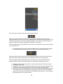
Nemo3D consists of three main components. The first is the design application (Nemo3D), which
also contains the second main component, the graphics engine (NemoEngine), while the third is
the playback application (NemoPlay) which operates as a separate application. The player and
the designer can be installed on the same PC or on different PCs, in fact the player can be
installed practically on any PC, even a notebook computer. A single player can control up to eight
NemoEngines, independent of each other, plus, also independently, a so-called Preview channel.
Nemo3D is based on real time 3D graphics. At present there are two PC-based, real time 3D
graphic development systems, OpenGI and DirectX (Direct3D). The former has been developed
originally by Silicon Graphics, the latter by Microsoft (consequently it runs only on Windows,
unlike OpenGI). Both are constantly upgraded and improved all the time. It is a matter of debate
which one is better, in fact probably neither can be considered better than the other one.
Professional, high end broadcast graphic systems, with the exception of Wasp3D, use OpenGI,
mainly either because they are not being developed in a Windows environment, or because they
were developed originally for Silicon Graphics.
Nemo3D is also based on OpenGI, as at the time, for no special reason, we have opted for it. It
could be just as well based on DirectX, as it has been made for the Windows operating system
and can be operated only in it. This does not present any advantage or disadvantage. It should
be borne in mind that in the course of learning the use of the application, parameters and
expressions will come up which originate from OpenGI. If the user has some experience with
OpenGI programing, he (or she) will find it easier to work with Nemo, but this is by no means an
indispensable condition.
It is not absolutely necessary to have some knowledge in mathematics (algebra, geometry),
although this is not a disadvantage, either. We, the developers of the system, can hardly claim to
be experts, so we can promise that it will not be too painful.
To learn the use of Nemo it is a definite advantage to have some experience in the use of one of
the 3D animation packages. Strictly speaking, Nemo is also a 3D animation application, with a
restricted and hardware dependent set of features that all work in real time. The other difference
is the handling of text, which is of primary importance and is much more sophisticated in Nemo3D
than in a 3D animation application.
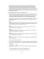
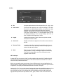
Hardware requirements
NemoEngine is resolution independent, in other words, the size of the picture is indifferent. Being
a broadcast graphic system, resolution is determined by the broadcast standard to be used. It can
be standard resolution (SD), either NTSC used in the United States and in some other countries,
such as Japan, or PAL which is preferred in other parts of the world. Increasingly spreading is HD
i.e. high definition ensuring a much higher picture quality. This term, too, is not uniform, HD is a
collective term for a number of video standards of different sizes and properties. HD consists of
approximately five times the number of pixels as SD. This puts a far bigger load on the graphic
card and on the CPU.
As it was one of our chief aims to put together a system available at a most advantageous price for commercial reasons and in accordance with our own purposes, too - it was our intention to
3
support hardware that are in widespread use and are marketed by their manufacturers as 'mass
products' - insofar as this can be said about products of the broadcast industry,- with an excellent
price value ratio.
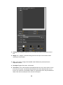
1. The products of the following manufacturers are supported as broadcast video hardware:
a. All Blackmagic Decklink cards or Multibridge boxes. Some of the cards do not support
some or all form of keying, these are not very useful for a CG application. See the
Blackmagic web site for details.
The Blackmagic cards are of good quality, easy to use and cheap. When used for CG however
they have one rather big disadvantage: they only work as either as input or as an output device
but not simultaneously. Therefore Nemo can use them only to output video and key signals,
there is no real time video input. For simultaneous input, you need to use a second card.
b. Bluefish444 Greed and its derivatives, Epoch Series, Supernova series.
Bluefish is a recognized name in the world of broadcast PC products. Justifiably so due to the
quality and reliability of their product. The Greed line of cards use SD definition, some of them are
output or input only. Epoch is the new line of Bluefish cards that supports SD and HD and is a
tremendous value for money. Supernova is their latest card that offers the best in flexibility, all of
their connections can be configured as either input or output. This is the best card for dual
channel operation.
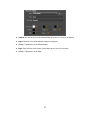
c. DVS SD Station Pro, Centaurus II, Centaurus II LT, Atomix line
DVS is a German company also well respected in the broadcast industry and are the
manufacturers of excellent quality boards. For HD resolution and simultaneous input and output,
both the Centaurus II and Centaurus II LT cards are supported.
d. For template design or preview output, a good VGA card is all that is required.
2.
In addition to cards producing broadcast signals, the most important part of the system is the
GPU (i.e the VGA card that works as a 3D accelerator as well). Nemo basically supports cards
made by nVidia, among them those equipped with the G80 or newer series GPU (since the fall of
2006 all of them belong in that category). We still experience issues with AMD cards therefore
they are not recommended. If it comes to the question of buying a new card, an Nvidia GTX650
would be the minimum you need, probably well suited for general, SD resolution tasks. Especially
for HD purposes, the optimum choice would be the best Quadro board, the fastest (and of course
the most expensive) one. You could opt for the best of the much lower priced Geforce line with
confidence, though. The current top of the line is the GTX780, but we could achieve very good
performance even with dual HD output using the 'lower high-end' GTX760 and GTX660.
3. CPU:
3D requires at least a dual core CPU, although its suitability is limited. For template design and if
only VGA output is used, a faster dual core processor is OK. In all other cases the minimum
requirement is a quad core or more. Nowadays this is not an extraordinary requirement. For HD
resolution, even the fastest possible I7 quad-core processor would not be excessive.
4
4. Memory, hard disk:
The minimum amount of RAM is 8GB, although more could be better. The hard disk requirement
is significant only if we intend to play several AVI files at the same time, or one AVI but with a
low if any compression HD resolution. In this case an SSD drive or Raid storage would be the
solution. Otherwise a conventional IDE or SATA standard disk would also do.
5. Display:
We tried to make the GUI as compact as possible with the cramped space of an OB van in mind.
The minimum useble size is 20” (1680*1050). We very much recommend a monitor of any size
with full HD (1920*1080) resolution.
6. Operating system:
Nemo3D runs exclusively on 64-bit Windows. Windows 7 and Windows 8 versions are both
supported.
Terminology
Before embarking on the detailed description of the programs, a few words about the terms
frequently used in the manual. Just like almost all computer software, Nemo, too, has its special
key expressions, fantasy-made and admittedly somewhat childish. Nautilus, the name of our
company, refers to the legendary submarine called Nautilus, and Nemo as her captain. The
words Nemo, NemoEngine, NemoPlay are similar references. The expressions will not surprise
any Windows user acquainted with various 'wizards'.
The basic file type used by Nemo3D is
Page Collection (PCO)
or if you like, a book which is the collection of all the graphics of a given design. We could have
named it Project, but it would have been too simple and common. Each Page Collection consists
of any number of
Pages
(surprise, surprise!) A Page is the logical unit of a graphic. Graphic elements can be placed on
separate Pages or on the same Page deemed optimal from logical and operational point of view
(see later in greater detail).
Each Page is built or composed of any number of
Objects
which are the building blocks of a Page. Objects are of different types, and each has various
Properties. Some of the properties (e.g. location in 3D space) characterizes every Object and are
therefore called Common Properties, but most of the properties are characteristic only of the
specific type of Object in question.
Most Objects have colour, material, and sometimes texture. A texture may be a bitmap image or
video (a pre-recorded clip or a live camera feed).
5
In Nemo3D, the name of the material is, understandably,
Material,
a texture is called
Texture.
Within a Page, it is possible to define several
Actions. No new Object can be created in an Action, but with the Objects already created for the
Page itself, different transformations and animations can be defined for each Action. The simplest
Action is usually made to animate off screen all displayed graphic elements which can be
achieved by animation from the current state (location, size, transparency) into one that can no
longer be seen.
Nemo3D is a template based graphic designer. The designed graphic serves as a model for later
use. A graphic has constant and variable elements. A common lower third graphic designed to
name various guests of a TV show consists of a strap, maybe a logo and the text itself. Only the
text is variable, e.g. the name of a participant of a show to which other information may be added.
In NemoPlay only these variable elements need to be filled in, and the actualized graphic can be
played back immediately. In order for NemoPlay to know which are the variable elements of a
certain Page or Action, these should be tagged in the designing phase. This purpose is served by
Imports
An import designates one of the variable elements of a given graphic. Imports are given individual
numerical IDs so that NemoPlay can identify them.
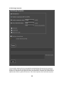
I. Page Collection, Page
The data of a Page Collection can be processed, one at a time. Consequently, the items of the
File menu well known from all Windows applications (New, Open, Save, Save As) serve to
operate also on Collection files. The name of the active Page Collection also appears on the
Toolbar.
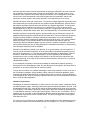
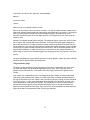
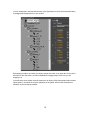
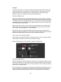
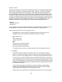
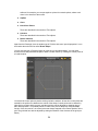
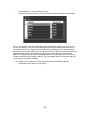
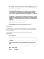
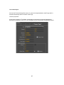
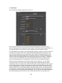
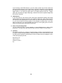
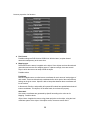
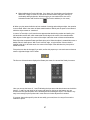
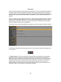
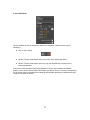
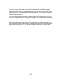
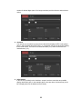
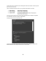
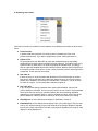
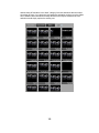
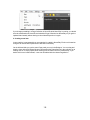
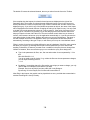
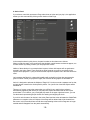
From version 2.6 of Nemo3D there is a new Pages panel where Pages are listed as thumbnail
icons and by their names as well. When you create a new Page, its default thumbnail picture is
the logo of Nemo3D but you can replace it with your own any time by clicking on Save Thumbnail
in the Tools menu. You can create a thumbnail at the moment in the animation you think is the
most representative of that particular template. The thumbnails for Actions are a bit smaller to
indicate their relationship to the Page itself and their border colour is dark blue instead of the
lighter blue of the thumbnail of the Page. If you click on any of the thumbnails its border becomes
bright yellow and the corresponding Page or Action gets selected.
6
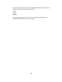
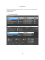
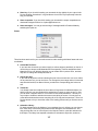
New
It creates a new Collection, and it creates at the same time a folder with a name identical to the
name of the collection, and within this folder, five further folders to store different types of files
related to the project. Although the paths of these folders are optional, the recommended and
offered location is \Nemo3DData\CollectionName. The following are the three further folders
created by the program within the Collection folder:
3DModels: for storing 3D models to be imported into the program,
Fonts: Place for fonts converted to an adequate format
Misc: Miscellaneous files like sound, etc.
Images: for storing Bitmaps, image sequences and AVI files.
Thumbnails: to store Thumbnail images representing the Pages and Actions of the Collection.
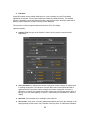
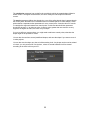
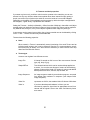
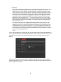
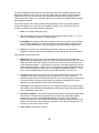
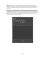
Open
Within this menu, the desired Collection file (with pco extension) can be found on the disk. The
application stores four filenames last edited, but by clicking on Browse we can look for files
anywhere on the disk.
7
Save, Save As, Exit
These are self-explanatory for anyone who has ever used a Windows application.
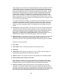
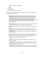
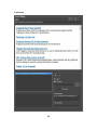
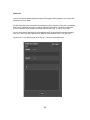
Restore
Nemo aims at maximum safety, every time something is saved- and this is done in the
background automatically and quite frequently - , it creates a backup. You can set the maximum
number of backup files in the Edit->Preferences menu. The maximum is 20, so up to twenty
versions of the same collection ensure that no amount of work would be lost. The backup files
always show their creation date and time in their file names. You can use Restore to choose the
version you want the current one to revert to.
A new Page or Action can be created by choosing New Page or New Action from the Insert Menu
and they can be deleted by using Delete Page/Action from the Edit Menu. The names of Pages
and Actions can be changed by double clicking on them in the Pages Panel.
8
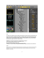
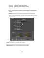
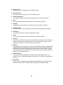
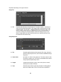
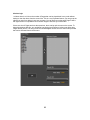
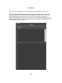
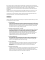
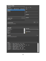
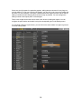
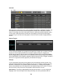
I. Objects and their properties
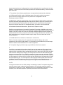
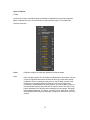
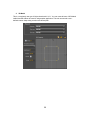
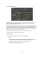
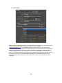
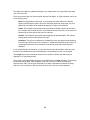
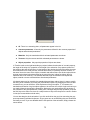
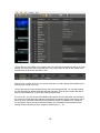
The objects of the currently selected Page can be found in the Objects panel. The Toolbar, too,
always shows the name of the selected Page and the name of the currently selected Object.
When choosing a new Page, objects appearing up till then are deleted from the screen. If,
however, we click on the name of the new Page with the Shift button pressed at the same time,
the objects of the new Page appear without removing those already there. Since Objects of
Pages can easily co-exist during playback this is an important function that helps us in the design
phase.
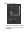
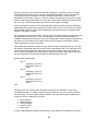
Objects can be created by choosing one of the items in the Insert menu and removed by
choosing Delete Object from the Edit menu.
9
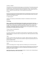
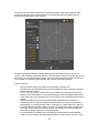
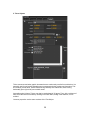
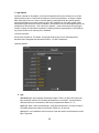
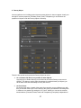
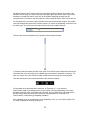
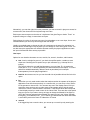
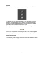
You can change their order and their hierarchy (the significance of which will be described later)
by dragging and dropping them on one another.
By dropping one object on another you simply change their order, if you press the Ctrl key at the
same time of the drop action, you also subordinate the dragged object to the one you are
dropping it on.
In the hierarchy the so-called common properties of an object (child) subordinated under another
object (parent) can inherit the common properties of the parent, which makes simultaneous
animation of several objects possible.
10
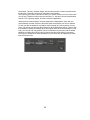
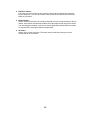
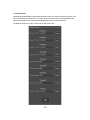
Types of Objects:
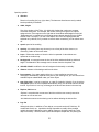
1. Text
It is the most common, and Nemo being a broadcast CG application also the most important
object. It handles text of one or several lines. As with most other types, a Text Object has
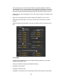
Common Properties:
Enable:
Enables the Object for rendering. Otherwise it remains hidden.
Layer:
Nemo can place objects in 8 virtual layers independent of one another. The use
of layers is significant because a situation can arise very often when real 3D
perspective view is not what you really need. In real 3D what is closer to the
camera covers everything behind it. However if you want to show a logo
permanently, independently of all other graphics, you have to place it closer to
the camera than anything else, otherwise it may be overlaid. This may be very
hard or impossible to do and the closer something is to the camera, the bigger
the perspective distortion. If, however, you place it on an upper layer, it will be
above anything else being on a lower layer, irrespective of how far it is from the
camera.
11
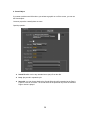
Translate x, y, z:
Spacial location in the coordinate system
Rotate x, y, z:
Rotation in space (in degrees) in relation to axis x, y, or z
Scale x, y, z:
Size of object compared to the original (1,1,1 = original size)
Transparency:
0=fully transparent, 1=fully opaque.
The button with the letter R in the lower right hand corner of the panel (reset
button) serves to reset all common properties to their default value (in the case
of scale and transparency it is 1, with other parameters it is 0).
12
The Text Object also has a great number of special properties:
•
the text itself: this may be a typewritten text or one given as a Unicode (UTF-16) txt file.
Nemo3D fully supports Unicode with the exception of complex scripts and Oriental
languages. If the text is saved e.g. from Microsoft Word, the Unicode Text option should
be chosen.
•
Font: you can choose any of the installed fonts for your Windows. You can also change
the style (bold, italic or both). If the text you type contains characters that do not exist in
the chosen font, the application will try to replace the font with another one that supports
those characters/languages.
13
Text type
This can be either 3D or CG. 3D text consists of polygons just like any 3D models and
can be extruded to give it real depth. It also scales very well. CG type text gives you a
traditional look and it is bitmap based. You can easily define color blends, edges,
shadows, but since it is a bitmap, it scales less well than 3D text.
Properties of 3D type text:
•
quality: This setting influences how the application should convert truetype to polygons.
The higher the value the more polygon the convertsion will result in and the more closely
it will follow the curves of rounded characters. If you do not plan to show that particaular
text object close to the camera (big in size), higher settings could result in a higher load
on the GPU without a good reason.
•
Material (face and extrude): you can choose from this dropdown list of already defined
materials by clicking on their names. Separate Materials can be used for the font face
and – in case it is an extruded font – for the extrusion.
•
shadow/edge: These are 2D effects probably familiar for those who worked with 2D
graphics. Actually drop shadow is a copy of the text placed by Nemo behind the text as a
fake shadow and the edge is drawn as a contour around the characters.
•
colour: colour of the edge/drop shadow
•
offsetx, offsety: position of the shadow in relation to the text. If you use an edge instead
of the shadow, only offsetx is used to set the width of the edge.
•
opacity: the transparency of the shadow (1=opaque, 0=transparent)
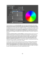
Properties of CG type text:
•
quality: The higher the value the bigger the resolution of the bitmap the characters of the
text will be rendered to, but also the more time it needs for rendering. The same applies
as for 3D text: if you plan to position or size the text object to remain relatively small, you
should not use a higher setting.
•
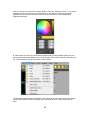
There is a blend of colours between colorStart and ColorEnd that represents the color of
the face of the font. By default the blend is defined with two colors represented by the
elliptically shaped dots placed below the strip. You can add another color by double
14
clicking at the place you want a new color element created (the maximum number of
color elements is four). You can drag these dots to change their placement. If you right
click on the dot, you can change the color and transparency of that element, and you can
also delete unwanted elements by holding the Shift key and double clicking on the dot.
•
shadow: the size of the drop shadow; color: its color; angle: its angle (0 is straight up, 90
is to the left).
•
edge: size of the edge defined around the shape of the characters; color: its color.
•
double sided: check this option if you want to view the text from behind (e.g. rotate it
around).
•
affected by lights: check this option if you want your lights to affect the rendering of the
text.
Font settings:
•
monospace: the characters of the text are placed equally in distance to one another.
Usually used for digital clocks.
•
kerning: extra distance between the individual characters.
•
charWidth: character width
•
charHeight: character height
•
maxWidth: if you need the text to occupy only a certain amount of space on the screen,
15
you can set this parameter to the size of this space. Nemo will try and change the
parameters of the font to squeeze it until it meets this requirement.
If maxWidth>0, by reducing first the kerning, then if necessary charWidth and if that is
still not enough, the charHeight parameter Nemo attempts to compress the text to fit the
size set by maxWidth. You can also set the minimum value of these properties (kerning,
width and height) below which it should not get decreased in the process of compressing
the text to the size set by maxWidth.
•
justifyX: justify horizontally. It is possible to justify to the left, to the center and to the right.
•
justifyY: justify vertically. Possible values are bottom, middle and top.
•
wordwrap: splits the text into lines but keep words intact.
•
typeWriter: this is an old CG effect in which characters appear one after the other. If the
value is 1, all characters are visible, if it is 0, none. If you animate this parameter from 0
to 1, you achieve a typewriter effect with definable speed.
•
tWfade: used for the typewriter effect, it sets the amount of fade between characters that
are already visible and those that are not.
•
character animation: switching on and off the animation of individual characters in a text.
•
charOffsetX, charOffsetY, charOffsetZ: The distance between the characters of the text
increases with the value set for these parameters (along axis x, y, z). By animating this
value in such a way that the final value is 0, characters 'fly in' one by one.
•
charOffsetT: Adds a time offset to values set for the previous three properties. The
maximum value is 20 and is measured in frames (of which in SD PAL there are 25 in a
second).
•
background: you can place a rectangular strap behind the text. Its size is always defined
by the size of the text in the x,y direction. The material for this strap can be chosen from a
dropdown list of available Materials.
•
offsetL, offsetR, offsetB, offsetT: if you wish to create a strap bigger than the text itself,
this can be done in all directions (L=left, R=right, B=bottom, T=top).
ClipBox parameters:
For each Object this box defines the boundaries of its existence in 3D space. Parts of the Object
that lie outside of this box are not visible. The box itself is created as the intersection of six
planes. These are called the clipping planes. The name of the planes are as follows:
L=left
R=right
B=bottom
T=top
N=near
F=far
16
Each of the six clipping planes can be switched on or off by clicking on their corresponding
buttons, or can be moved or transformed in relation to their default value (which is 0). The value 0
is always adjusted to the edge of the object. If, for instance, clipping plane L is switched on and
its value is 0, it is exactly on the left hand edge of the object. If you increase this value, the object
starts to become invisible. By the time the value reaches 1, the object is totally invisible.
With the help of a ClipBox any wipe effect can be created easily, and in any direction in 3D
space.
●
●
global: if this parameter is on, the clipping planes are not calculated in the relative
coordinate system of the object itself but rather in the global coordinate system. This is
important if you want to create a push effect where the clipbox remains at the same place
while the object itself moves in from somewhere outside of the box.
Link to Dummy: To make it easier to set the same clipbox for several objects animated
together, it is possible to link to clipbox parameters to that of a Dummy object.
Clone parameters:
When making charts, tables or team line-ups for sports graphics where there are quite a few
rows of text with the same properties but with different text, it would be very difficult to define
each row as a separate object.
The clone is meant to solve this problem. With the help of the clone you can define several
objects with identical properties except their content (the text itself) as one object and also
animate them as one.
●
Number: The number of clones. Maximum value is 100.
●
Offset x, y, z: the relative distance of a clone calculated in relation to the location of the
previous clone (e.g. the distance of the second clone from the first, etc).
●
Offset time: it gives the time difference, that is, it indicates how much later a given clone
reaches during animation the same point as the clone preceding it, which makes it
possible to create attractive snakelike wriggling movements.
17
●
RowMax: If this number is bigger than 0, the clones will not align alongside a one
dimensional line, but rather in two dimensions like elements in a grid. RowMax
designates the number of clones to be placed in one row. If the number of clones is, say,
48, and RowMax=6, then 48 clones will be placed in 8 rows with each row having 6
clones.
●
ColumnMax: If its value is bigger than 0, the clones will be placed as elements of a 3D
grid. If, e.g. there are 96 clones, and RowMax=6, ColumnMax=8, then the clones will be
placed in eight rows, six columns and on two layers (6*8*2=96). This will hardly be useful
but looks impressive at least.
●
Clone sep: If you don't want to enter multiple lines of text for any of the clones, you
should set this to single line. This way every line of text will be used as content of
separate clones. However, if one or more of the clones should have content consisting of
multiple lines, you should leave the setting to multiline (default value). With this setting,
the text will be separated with the ## tag described on the next page.
18
Inherit from Parent
Objects can be placed in a hierarchy above and below each other. An example illustrating this is
when the text to be shown on a strap is below the strap in hierarchy. This way it is sufficient to
move or rotate the strap itself, the text will follow, in other words, “inherit” the change in the
common parameters of the strap. They would be in a so called parent-child relationship, where
the strap is the parent, as it is higher up in the hierarchy, and the text is the child. There can be,
of course, a multiple hierarchy, where the parent is the child of another Object. Parameters to be
inherited from the parent can be limited, in fact, only the common (translation, rotation, scale and
transparency) properties can be inherited. Sometimes it may be a disadvantage if the child
inherits the change of all common parameters. Therefore inheriting the parameters of
- translate
- rotate and scale and
- transparency
can be switched on or off. For mathematical reasons, rotating and scaling can be switched on or
off only together, simultaneously, but it is unlikely that this could be a major limitation.
Special characters which can be used as tags in the text:
[enter]##[enter] In case the specific Text object has several clones, the text to be
displayed by each clone should be separated with this tag. An example:
Text of the first clone
##
of the second clone,
though several lines
long
##
From this point, text of the third clone.
If there are more clones than three,
all the other ones will show this text.
For single line clones, you can use single line as the Clone sep setting (see above).
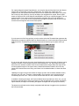
●
Linked to
It is possible to link the property of an object to the value of the property of another
object. If, for example, you want to make a bar chart, you can link the height (Scale Y) of
the bar to the value of text displayed below it. The height will get adjusted automatically.
For this to work, you have to choose the source object and its property you want the link
to be established with from the drop down lists, then choose target property of the current
object. If the linked property is numeric value, you can scale it to get an appropriate result
by setting the offset and bias values (the original value will be multiplied by the bias then
the offset will be added to it.
If you link the text property of a text object to a numeric property of another object,
because you want to display that value on screen, you can set the number of digits
displayed after the decimal point by setting the decimal value.
Another option if you want the result to depend on distinct values of the source property,
19
you can map these values by checking the Mapped checkbox and typing in lines of
equations in the map textbox something like this:
1=blue
2=green
3=red
4=yellow
If the source property has a value of 1,2,3 or 4, the target property will get the
corresponding value (blue, green, red or yellow).
20
●
Render switches
By setting these options you control which of the advanced rendering switches you want to use.
Since these features all require a lot of rendering power and even the fastest GPU can quickly
reach its limit with multiple per pixel lights, shadows and reflections, a lot of care should be taken
when setting these options.
Although you can set which of your lights should be calculated per pixel instead of per vertex, you
can control the effect of that setting for every object independently. For a detailed model with lots
of polygons that covers a relatively small part of the screen per pixel lighting is definitely overkill.
But for moderately detailed or simple models with fewer polygons that cover a large part of the
screen, per pixel lighting improves the final outlook tremendously.
Similar thinking can optimize the rendering power of your hardware when you set which object
makes sense to appear as reflection in a mirror, or casts shadow on another object for which the
receives shadow option has been set. For example, the walls of a room should receive shadows
but they probably don't cast shadows on anything.
For objects to self shadow, you have to switch on both the casts shadow and the receives
shadow options.
The best way not to run out of the rendering power of the GPU is to only switch the necessary
options on one by one and always checking if it really adds a great deal to the realism of the
scene. Otherwise it is best to leave them switched off.
For any video mode that is interlaced (NTSC, PAL or HD 1080i modes) a deflicker filter on top of
normal antialiasing ensures smooth edges and motion. This is a so called post processing filter
and does not come free (i.e. it adds to the load of the GPU). Most of the time when there are only
computer generated elements on screen the whole scene should be deflickered (this is the
default setting that can be switched on and off as a property of the camera). But if for example
you put a recorded video or a live feed as a background for your scene, filtering it would degrade
its quality. In this case, you can switch the global deflicker checkbox off and switch the flicker filter
on or off on an object to object basis.
21
2. Primitives
Simple 3D models can be created inside Nemo, it is not necessary to use a 3D modelling
application for this task. These simple models are collectively called primitives. The simplest
primitive, Rectangle, has several special functions, and special mention should be made also of
piechart, which could be a big help in making circular diagrams.
They have the common properties identical with those of the Text Object.
Special properties:
●
primitive Type: the type of the Primitive. See the list for yourself, it should be selfexplanatory.
●
slices and stacks: it indicates the number of polygons (usually triangles or quads) used
in creating the primitive. The influence of these values can be best appreciated with a
sphere primitive. Even with a simple rectangle the number of polygons can make a
difference. In OpenGl, the greater the number of polygons, the more precise the effect of
lighting (if you use vertex lighting, of course, in case of per pixel calculations, it does not
matter).
●
two sided, if the backside of the rectangle is also required.
●
fit to screen: in this case - no matter what transformations are set for the rectangle, it will
always perfectly fill the screen. Only Translate Z has any effect, as it defines the distance
22
of the rectangle to the camera so the rectangle fitting the screen can be placed in front of
or behind other objects. If a live video is placed on the rectangle and you also use the
chroma keyer (see further details later on), you at once obtain a basic virtual studio. By
keying out the background in the live feed and just keeping the main element – usually
the presenter of the foreground you can place computer created graphics behind the
presenter (with a distance in Z bigger than our rectangle) and other elements in front
(closer than the rectangle). This function can also be used to place a texture of a still
image or sequence or even an AVI file as the background of the whole scene. You just
need to apply this texture on the material of the rectangle and move the rectangle very far
so it won't cover any other objects.
If you want to animate the rectangle, you cannot fix its size to full screen, but you can set
its translation parameters to cover the screen by clicking on the 'S' button next to the
checkbox. Only the current value of the Scale X parameter will be taken into account
though, you have to manually set Scale Y according to the correct aspect ratio of the
screen.
●
Tex adj. button: This can be useful if you want to use a cutout of the texture applied on a
rectangle. This button works as a toggle, switched on it turns red, and lets you use the
mouse and its left button to define a rectangular area in the Preview Window which will
let you crop the applied texture by modifying its offsetX, offsetY, sizeX and sizeY
parameters. You should switch on fit to screen before you use this function. If you are
satisfied with the settings, click on the button again to use the new settings.
●
Reflective mirror: by switching this option on, the rectangle becomes a mirror, and it will
reflect those objects that have their corresponding rendering switch turned on. The
reflectivity of the mirror can be adjusted by setting the reflectivity property of its material.
Properties of all other primitives:
●
inner radius
●
outer radius (it has no meaning with spheres, but it has with a torus).
●
start angle
●
sweep angle: central angle of the segment of a circle. Together with start angle, it is
useful only with the partial disk and the piechart primitives.
●
material: material of the primitive chosen from the dropdown list of available materials.
●
texture offsetX, texture offsetY, sizeX, sizeY
When a texture is defined for the material, the texture can be transformed by setting
these parameters. The offset values translate the texture coordinates, the size values
scale them and the texture is magnified or shrunk and repeated on the primitive.
●
stretch over clones: it works with any primitive, but it is probably only useful with
rectangles. You can define several clones of the same rectangle, placing them next to
each other as elements of a 2D grid. Using this option means that the texture defined for
the material will not be repeated on the individual clones, but each clone will obtain only a
part of the whole texture. By animating the clones very interesting effects can be
23
achieved, for example, you can put together a photo from mosaic pieces, where each
clone is one element of the mosaic.
●
ClipBox
●
Clone
●
Inherit from Parent
These are described in the section of Text objects.
●
Linked to
These are described in the section of Text objects.
●
Render switches
These are described in the section of Text objects.
Apart from the Rectangle, there is another type of Primitive with some 'special properties'. It can
be found at the end of the list called 'Drawn Shape'.
You can use this type of Primitive Object to create one or two sided shapes. You can either
choose from several predefined shapes or draw a closed contour by creating the control points of
a Cardinal spline.
You create the control points by double clicking inside the window. At least four control points are
needed for the spline to be drawn as the outline of the shape. Control points can be deleted by
right-clicking on them with the mouse, and their position can be adjusted by dragging them to
their desired position. It is probably easier to create more precise shapes by using the snap
function. If this is turned on, the control points are always snapped to the nearest position on the
grid. The grid itself can also be adjusted by setting the distance of the elements of the grid (see
above).
24
The subdivision parameter lets you define the precision by which the created shape follows its
drawn contour. The higher the subdivision, the more closely the final shape will follow the
contour.
The tension parameter defines how sharply the curve of the spline bends when it passes through
the control points. Nemo3D uses a modified version of Cardinal splines to create shapes. These
splines define a separate tension parameters for every control point. A tension value of 0 results
in a straight line segment between two control points. In this case the subdivision parameter
should also be set to 1, its minimum value. A tension value greater than one results in a curvy
segment, the higher the value, the more curvy its shape.
If you try to define a concave shape, you might need to add more control points, otherwise the
shape might not be possible to create.
You can also choose from several predefined shapes, and save the shape if you want to reuse it
in other projects.
You can also use the shape you draw to build an analog clock. Any shape can be used as a hand
of a clock, you only need to set if its the hour, minute or second hand and it will be rotated
according to the clock built into your PC.
25
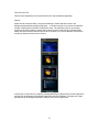
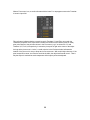
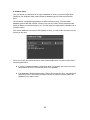
3. 3D Model
This is a completely new type of Object introduced in V3.1. You can create all sorts of 3D Models
inside Nemo3D without the need of using another application. This tool can extrude a userdefined contour shape along an also user-defined path.
26
The contour can be created the same way as the Shape Primitive with the exception that this
contour does not have to be closed and there is an extra Scale parameter adjusting its size
compared to the path used for the extrusion.
The path is yet another modified Cardinal-spline based shape, drawn the same way as the
contour of the 3D Model or the Shape Primitive. The path can be closed or unclosed, and you can
also check if you want the end caps created. You can set three materials to define the final look
of your model. One material for the extrusion itself, and two for the two end caps.
Other settings are:
–
–
–
–
–
Smooth normals: check if you want a less segmented, smoother look.
Rounded joins: this setting influences the way the segments of the model will connect at
specific points of the path.
Tx, Ty, R, Sx, Sy: You can transform the contour shape at every point of the path. The
transform is 2D, and Rotation is only possible along the Z axis. By adjusting just the size
of the contour (Sx, Sy) at the path points, you can easily create a beveled extrusion of the
contour.
PathStart, PathEnd: These are the only animatable parameters of the extrusion. It
defines the number of segments that will actually be drawn on screen. If PathStart is 0
and PathEnd is 1, all segments are drawn, if PathStart is 0.5 and PathEnd is 1 then only
the second half of the model is drawn. Of course, the greater the number of segments of
the model, influenced by the subdivision setting, the more precise is the animation you
can create by setting keyframes for these parameters.
Auto: If checked, any change in any of the settings will automatically update the final
model. If you use complex and more detailed contours or paths this can result in a much
27
–
slower response, so use this setting with care.
Create: by clicking on the button, the model will be created using all the current settings.
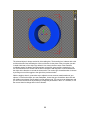
There is a very specific use for the 3D Model object, and this is the creation of a Pie Chart. You
can use any shape to create a Pie Chart, although the path itself probably should be circular. If
you enable the Pie Chart, instead of the three materials you assigned for the extrusion and the
end caps will not be used. Instead, you can add any number from the list of existing Materials and
add a percentage value to define what percentage of your model should be covered by that
Material. If you want four pies, than four Materials should be set, and setting the Pie size to 25%
for each would result in four equally sized pies. If the percentage values you set do not add up to
100, the last pie is resized accordingly.
●
ClipBox, Clone, Inherit from Parent, Linked to properties and Render switches
are described in the section of Text objects.
28
4. Imported Model Objects
Although Nemo has a 3D modeler of its own, it can also import models from practically any
modeler or 3D animation application (including, amongst others: 3D Studio Max, Maya,
Softimage, Houdini, Lightwave, Cinema 4D.)
Because of real time rendering, there are some restrictions. Only so called polygon-based models
can be imported, where a model is made up from a series of coplanar polygons (generally
triangles or quadrilaterals or quads). If a sufficiently high number of these elements are used,
even curved surfaces appear to be smooth and continuous. In Nemo3D not only objects of this
type are made of polygons, but all objects, including Text.
Information on importing models can be found in the 'Import 3D Models' chapter.
Common properties: The same as those of Text objects.
Specific properties:
●
Name: The name you give to your model in the Object Panel.
●
Material:
When importing a model Nemo also creates all the materials which were used in the
modeler. But you can change the Material assigned to your Model any time.
●
ClipBox, Clone, Inherit from Parent, Linked to and Render switches
are described in the section of Text objects.
29
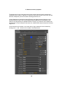
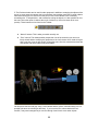
5. Ticker Objects
Ticker means text and other graphic elements that are continuously scrolled in one direction. It is
generally used for end credits, displaying sms messages and other continuous information. This
is a relatively recent name, earlier tickers moving vertically were called rolls, those moving
horizontally (from right to left) were called crawls.
As anything else in Nemo, Tickers can also be manipulated in 3D space. Thus, with a minimum of
effort, even the famous introductory scrolling text of Star Wars, fading in the distance, can be
realized.
Common properties: are the same as those of the Text Object.
30
Special properties:
●
direction
Direction of scrolling (left, up, right, down). The latter two directions are rarely needed,
but the possibility is available.
●
width, height:
Size of the window of the Ticker. It is within this window that continuous, constant
movement takes place. For example, with a ticker moving from right to left, objects
assigned to the Ticker appear on the right side of the window and disappear on the left.
“Disappearance” is created by the six clipping planes (already described in the ClipBox
section of the Text object). For the Ticker object, four of the six clipping planes are
switched on by default, but if you want to remove these constraints, you can switch them
off.
●
speed: speed of the scrolling
●
spacing: It is used to place any element (or row of text) of the ticker closer to, or
conversely, farther off from each other.
●
loops: Defines the number of times the ticker is repeated. A value below zero
represents an endless loop.
●
background: a rectangular area the size of the ticker window defined by width and
height. The Material for this rectangle can be chosen from the drop down list.
●
offsetW, offsetH: modifies the size of background horizontally or vertically.
●
distance: distance of the background from the ticker.
●
line separator: if you want another object (e.g. a logo applied as a texture on a
rectangle) to automatically separate every line of your scrolling text, you can choose from
available objects subordinated under your ticker object.
●
text of the ticker, it can be a typed text, or a text file (coded in Unicode). If you check the
autoupdate option, the text is updated automatically every five seconds from the chosen
text file. If your ticker is in a loop, all changes in the text file are shown in the next loop.
●
Replace, Add buttons:
Replace: it overwrites the current text of the ticker with the text currently entered or
selected as a file as new text.
Add: Adds the new text to the existing one but without deleting the old text first.
●
logo list
Although the ticker, in addition to Text objects, can contain and scroll Primitives, 3D
models and Clocks, too, it would be virtually impossible to modify all the possible
variable elements in NemoPlay just by adding Imports to all objects below the Ticker
object in hierarchy. Therefore even a quite commonplace simple task, like placing the
31
varying logos of sponsors in the end credit would be extremely complicated. If for
example the number of sponsors and their logos would change from one show to the
next the template would need constant modification and update. To make this task
simple, the following solution is used: a list is compiled from the bitmap files of logos,
and the application automatically applies these bitmaps as textures on simple rectangles
and adds them to the scrolling ticker. The operator only needs to feed the filenames in
NemoPlay as Import data.
●
text of the ticker (typed in or read as a Unicode text file):
Although tickers usually show simple text made up of one font, it is possible to place
different text objects and objects of a different type. Objects to be used in a ticker should
be placed in the hierarchy below the ticker, as its “children”. When a new ticker is
created, it automatically creates the minimum number of one text object as its child.
For Nemo to know which text, logo or non-text type object should appear in a given part
of the ticker, special tags are used in the text of the ticker. You can choose from the
following tags:
#Txx_
It indicates the index number of the text object attached to the Ticker in hierarchy. XX is
always a two digit number, the first Text object among the children of the Ticker gets an
index number of 01, the second text object is 02, etc.
#Pxx_
From the Primitives that are children of the the ticker object, xx indicates the index
number (starting from 01, see above).
#Mxx_
From the 3D Model objects that are children of the the ticker object, xx indicates the
index number (starting from 01, see above).
#Cxx_
From the Clock objects that are children of the the ticker object, xx indicates the index
number (starting from 01, see above).
#Lxx_
From the list of bitmaps you add to the logo list, xx indicates the index number (starting
from 01, see above)
Other, optional parameters for logos:
Since logos are not individual objects with modifiable properties, there are optional data
that can be entered as part of the text of the ticker to help adjust certain parameters of
the logos:
J,xoff,yoff,size - where
J: justifying the logo within the text to left, centre or right (corresponding values L, C or
R).
xoff: horizontal translation in relation to the calculated coordinate
yoff: vertical translation in relation to the calculated coordinate
32
size: by default the size of the logo is 1 (if it is a rectangle and width and height are not
equal, the bigger dimension will have a size of 1, the smaller is proportionally lower).
'Size' serves to scale these values.
Example: #L01_C,0,0,2.2
Which means in plain English: show logo 1 from the list, justify it to the center of the
ticker window (C), x,y coordinates need not be modified (0,0) , but the size of the
rectangle - which by default takes its aspect ratio from the dimensions of the bitmap file
- should be multiplied by 2.2.
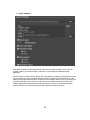
Separators:
You can define an element of the ticker to be the starting or ending element or also the
automatic line separator that separates all lines. Separators can be set using the same
tags as you can include in the text of the ticker (see the picture above). Each separator
is optional.
●
ClipBox: for its use see the description under Text object.
●
Clone: Tickers cannot be cloned. There is no point.
●
Inherit from Parent: For its use see the description under Text object.
6. Clock Objects
Like the Ticker object, in the hierarchy Clock is always a parent, because when it is created it
automatically gets a Text object as its child. This text object defines the parameters of the font
used to show the clock.
Common properties of a clock object: they are the same as those of Text object.
Special properties:
●
type: possible settings
System time shows the built-in clock of the computer, which is a conventional but fairly
precise clock.
Internal Timer: practically it works like a stop-watch and is based on the built-in clock of
the computer.
External Timer: a stop-watch but based on data information coming from an outside
source.
●
offset time: this should be used in conjunction to the System Time type. The value of
offset time is always deducted from the current system time and the result gets displayed.
●
format: possible settings
hh.mm
hh:mm:ss
hour, minute
hour, minute, second
33
hh:mm:ss.t
hh.mm:ss.tt
hh.mm:ss.ttt
hour, minute, second, tenth of a second
hour, minute, second, hundredth of a second
hour, minute, second, thousandth of a second
●
leading 0: this is the number of zeros to be placed at the beginning.
●
startAt: stop-watch function. The data for the starting time from which the stop-watch is
activated.
●
stopAt: stop-watch function. The data for the end time where the stop watch stops
counting.
●
Direction: direction of the stop-watch. 'Up' means it counts upwards, 'Down' means that it
counts downwards.
ClipBox: For its use see the description under Text object.
Clone: clones cannot be used with the Clock (it would make no sense).
Inherit from Parent: For its use see the description under Text object.
34
7. Light Objects
As Nemo is based on 3D graphics, to borrow the expressions from the real world, we view the
objects with the help of a camera and we light the environment with lights. An object is always
dark unless light is cast on it. Nemo uses the lighting models defined by the OpenGI graphic
system and endeavours to make maximum use of the capabilities of up-to-date graphic cards.
Nevertheless lights should be used in moderation, first because not more than eight lamps can be
switched on at the same time – this is the limit in OpenGl -, second, because by using a bigger
number of lamps the calculation requirement of lighting increases exponentially. It can easily put
too great a burden on the capacity of the hardware.
Common properties:
are the same as those of Text Object, except that the lamp has no size and transparency,
therefore Nemo disregards the parameters Scale X,Y,Z and Transparency.
Special properties:
●
type
directional light: with properties resembling sunlight. There is no place from where the
light emanates, therefore its Translate parameters are not relevant, only the direction
should be taken into consideration, defined by the parameters Rotate X, Y, Z.
point light, which, unlike directional light, gives light in all directions, so only its location
(Translate parameters) matters, its direction ( Rotate X,Y,Z) does not.
spot light: it is a combination of the former two. Both the location and the direction of the
light is important.
35
●
diffuse R, G, B:
the diffuse color of the light given as 8-bit RGB numbers
●
specular R, G, B:
the specular color of the light given as 8-bit RGB numbers
●
constant attenuation
the constant decrease of light intensity in proportion to the increase of distance
●
linear
linear decrease of light intensity in proportion to the increase of distance
●
quadratic
quadratic decrease of light intensity in proportion to the increase of distance
●
spotlight cutoff:
if the type of light is spot, cutoff gives the central angle of the light beam in degrees.
●
distribution:
if the type of light is spot, this gives the distribution of light.
●
active:
you can switch the light on and off by checking or unchecking this box.
●
Per pixel:
if switched on, the effects of the light will be calculated on every pixel of the screen and
not just at the smallest element of the model, the vertex. Makes the output a lot more
realistic but consumes a lot of GPU power. Use with caution.
●
Shadow:
Only spotlights can cast shadows. The type of shadows Nemo renders is called shadow
maps, and it involves rendering the scene from the point of view of the light itself. You
can check how the view from the light looks like by clicking on the 'D' button. The light
view will be shown in the Preview window in gray colours because shadow maps do not
contain colours, only depth values.
●
shadow softness:
You can set how soft the edges of the shadows look by adjusting this value. The
minimum value is 1 (hard edged shadow), the maximum is 12, which in most cases will
be to soft.
●
depth offset:
In order to avoid a problem that can happen with self-shadowing using shadow maps,
you can add a little offset to the depth values calculated for the shadow maps.
36
8. Dummy Object
It has a significant role in building up the hierarchy among objects. It does not appear visually, but
through its common properties (Translate, Rotate, Scale, Transparency) it can influence the
properties of objects under the Dummy Object in hierarchy.
There are two special functions that the Dummy Object can solve:
1. As a common Clip Box for any number of other Objects:
Any Object (incl. another Dummy) can be linked to the chosen Dummy to serve as its
Clip Box. This helps to use the same clip settings for a whole hierarchy of Objects, you
do not have to set them individually for every one of them.
2. As Free Clones:
By checking this option, instead of the usual Clone controls, you get a different one: with
this, you can still create up to a 100 Clones for the Dummy, but instead of animating them
in relation to one another (by setting the X,Y,Z and T offsets) you can use the common
transformations (Translate, Rotate, Scale and Transparency) completely independent of
37
one another. This way, whatever Object with the same number of clones is placed under
this Dummy in hierarchy can also be controlled in total freedom.
The only thing you have to remember is that if you choose a Dummy as Free Clones then
you can only Transform its first clone the usual way, i.e. with the Common transformation
controls. This is perfectly logical, all other clones are independent.
Although these clones and their common properties are independent, quite often you
would probably set most of these to the same values except those you want to animate.
To help you with the otherwise very tedious task of setting up to ten properties of every
clone, you can set one and copy these values for all the subsequent clones. There is also
the possiblity of adding an offset by which the original value will be incremented for every
copy. You can not only copy property values but animation keys as well, with the added
possibility of adding a time offset value, by which keyframe times will be incremented.
This way you can define the same animation for your clones, but all happening at a later
time then the previous.
38
9. Sound Object
If you want to add a sound effect when you animate a graphic on or off the screen, you can use
the Sound object.
Common properties: naturally there are none.
Special properties:
●
Sound file which can be any standard wave (wav) file on the disk.
●
Loop: play sound in repeated cycle.
●
Start with: you can choose whether the Sound Object should be attached to the Page it
is part of or one of its Actions. The sound effect will be produced only when the selected
Page or Action is played.
39
●
Start delay: timing, that is, the time difference with which playing the sound effect starts
later than playing the Page or Action in question. Measured in milliseconds.
●
Stops with: you can choose another Action from the list to stop the playback of the
sound.
●
Stop delay: timing, that is, the time difference with which stopping the sound effect
happens later than playing the Action set to stop playback. Measured in milliseconds.
●
Fade out length: Sound stops by slowly decreasing its volume (fade out). You can set
the length of the fade by adjusting this parameter.
●
Linked to:
You can trigger the playback of a sound by linking it to a property of a clock object. When
the value of that property is equal to the Trigger value you set, playback starts. Keep in
mind that the trigger value is measured in tenth of seconds.
40
10. Camera Object
We view the 3D world through the camera. A camera is always attached to each Page and it is
created automatically with the creation of the Page.
Common properties:
are the same as those of Text Object, except that the camera has no size and transparency,
therefore the parameters Scale X,Y,Z and Transparency are automatically disregarded by Nemo.
41
Special properties:
●
Type: possible settings:
Perspective: 'normal' perspective projection
orthographic 3D: orthographic, pseudo perspective projection
2D
●
Viewport: The size of the window in pixels as defined by the camera. It is identical to the
video resolution chosen, in the case of SD PAL it is 720 * 576 pixel.
●
Near Clip: The distance to the clipping plane close to the camera, objects that are closer
than this distance will not be seen or at least those parts closer than this limit will be
discarded for rendering.
●
Far Clip: The distance to the clipping plane beyond which objects or at least parts of
them will become invisible.
●
Field of View: The field of view parameter for the 'lens' of the camera. Measured in
degrees.
●
Depth of field: If you want to simulate the depth of field effect of a real camera lens,
check this option and set the focal distance and focal range parameters. Focal distance
ranges from 0 to 1, 0 is the location of the near clipping plane, and 1 the far clipping
plane. Focal range has a value also from 0 to 1, it sets the range from the focal point
where everything should be in focus.
The following properties do not belong to the properties of the camera, but as they
influence all objects of a Page, they are included here.
●
Ambient R,G,B: colour of the ambient light (in 8-bit RGB values).
●
Global Fade:
Global transparency influencing all objects of a Page. By animating this single parameter
you can fade all Objects of a Page in or out. Its minimum value should be zero
(everything being transparent), but it can be given a negative value, too, for a special and
significant reason. In Nemo more than one Page can be played back at a time so Objects
of any number of Pages can co-exist. If you want to animate off Objects of a Page and
discard them because they are no longer needed, you can do so by animating the
GlobalFade property until its value decreases below zero. At this point everything
becomes not only transparent, but because it is a negative value all Objects of that
particular Page will be deactivated and cease to exist (of course only until that Page is
played again).
●
Deflicker: By checking this option you ensure that everything in the scene will be flicker
filtered regardless of the settings of individual objects.
42
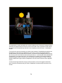
10. Particle Object
Particle system based effects have been in widespread use in movies for the last decades. Nemo
implements the Particle Systems API developed by David K. McAllister
(www.particlesystems.org). For a detailed description, see the web site. If you don't want to
spend some time experimenting with the various settings, you can also choose from the library of
predefined particle effects, choose the material you want (you can apply a texture on it as well).
The size of the particles are set according to the value of the Size property of the Material
settings. The particles themselves are drawn as point sprites which means that only their location
is calculated in 3D. There is no rotation since they always face the camera and their size is
calculated based on their distance from the camera but it is not a precise perspective correct
calculation.
43
11. Path Object
This is a new type of Object introduced in version 2.7
This object can work either as a rendered object that actually appears on screen or as an –
almost – arbitrary path other objects that are its 'children' in hierarchy follow during animation. If it
is a rendered object, it can be used e.g. to draw diagrams that are animated over time.
The Path Object itself is a spline curve that is defined by placing a number of Control Points (CP)
to anywhere in 3D space. Nemo uses modified Cardinal type splines because these are very
easy to control and all CPs lie on the spline itself. There is also a Tension parameter for each
control point that controls how tightly the curve bends at each point. A Tension paramater of 0
results in a linear line segment between two control points, the maximum value of 1 makes the
curve very round. The smoothest curve can be usually achieved if you set Tension to 0.5 for
every CP (this special case of a Cardinal spline is also known as the Catmull-Rom spline).
When you create a Path Object, the minimum number of CPs is always 4. You can always
increase this value if you need a more irregularly shaped path. New points will be created
automatically and you can place them either by choosing the currently selected CP and using the
X,Y,Z numeric controls or visually. For the latter you need to click on the Edit button first. If this
button is highlighted, the currently selected CP turns red instead of yellow. You can click on any
of them on screen. If you click with the middle mouse button then you can move this point in the
x,y direction by moving the mouse, and by rotating the mouse wheel you can move the point in
the z direction. If you are satisfied with the placement, you can click with the middle button again,
then choose another point you wish to move until all points are where you want them to be.
44
The shape of the spline is updated constantly so you always have a very good idea about what
your curve looks like.
There are several things you can accomplish with the Path Object. Its Type parameter can be set
to the following items:
–
Brush: During playback of the Page, a points sprite (the same used for the Particle
Object) moves along the spline. The size of the brush can be set as the point size of its
Material and its shape can be modified by applying a Texture on its Material.
–
Stroke: The full path is being drawn during animation the length of which can also been
set. The path may be drawn as a line if your Material is set to draw a line or as a series of
Brushes set the same way as the previous Path type.
–
Stroke2: The full path is being drawn then disappears in animation again. The relevant
settings are the same as with the previous type.
–
Animation: This type is not drawn at all, instead if there are any Objects subordinated to
the Path Object in hierarchy, their Translate X,Y,Z parameters follow the Path exactly. All
complicated movements are much easier to set this way then with normal keyframe
animation.
If you set the Path type to Animation, you can also set the rate of Acceleration at the start, and
the rate of Deceleration at the end of the animation. Values between 0 and 1 are accepted.
The Length of the Path in animation can be set as a number of frames, but that number is
displayed in TC (timecode) as well.
There is only one keyframeable parameter for the Path Object: its State parameter. This has only
two possible values (Stop, Play). Playback of the Path only occurs if there is at least one
keyframe set to Play. This way you can decide if you want to play back the Path for the Page
itself or for one of its Actions, and also at which point in time you want to start playback.
45
II . Materials and their properties
The appearance of most of the object types (except camera, light and sound) is determined
essentially by their material. “Material” is a collective name which means not only color, but also
shininess, transparency and several other rendering parameters, too.
In Nemo Materials are handled somewhat differently than Objects because Objects are only
created when their Page is active (being played back) but Materials can be attached to any
Object of any Page and form a separate collection or library. Any member of this collection can
be attached to a lot of the Objects at the same time, whether these objects are parts of the same
Page or not.
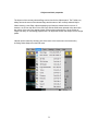
A new material can be created, or an existing but no longer needed one can be deleted by
clicking on the '+' and '-' buttons on the top right of the Materials tab.
46
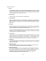
Properties of materials:
●
Name:
When a material is created, it is named automatically (consisting of the word Material and
an individual serial number), but this name can be modified later at any time. It is worth
while giving a tell-tale name easy to identify, as there are several places where materials
have to be identified and selected by their names.
●
Diffuse R,G,B
The diffuse (basic) color of the material in 8-bit RGB values.
●
Specular R,G,B
Color of the light spot shining on the material, given in 8-bit RGB. The color of Specular is
added to Diffuse, this is how the color of the light spot is achieved. If Specular is black
(RGB 0,0,0), there is no light spot, so the color of the object is determined only by the
Diffuse color.
●
Shininess
Basically it determines the size of the light spot so as to imitate shiny, metallic surfaces.
Its value ranges between 1 and 128, the lower the number the bigger the light spot of the
surface, though this is also influenced by the Specular color.
The final color of the objects depends not only on the Diffuse and Specular colors and on
Shininess, but also on lighting and the lights used. If there is no light, in spite of setting
nice and bright colors, the object will remain dark.
●
Transparency:
Transparency can be set for an Object but also for the Material, between 0 and 1 (0 being
totally transparent and 1 totally opaque). Transparency of the Object and that of the
Material are added (mathematically it means multiplication; a half transparent Object
together with a half transparent Material will be 25 % opaque and 75% transparent).
●
Reflectivity:
If the material is assigned to a reflective mirror, the reflectivity of the mirror is set with this
property. Minimum value is 0 (no reflections at all), the maximum is 1 (the mirror will
reflect 100% of the light).
●
Affected by lights:
Even if the lights are switched off, they do not affect the appearance, objects “covered”
with this material will show a uniform Diffuse color with no shading.
●
Enable Texture Array:
This is a very useful setting for clones. For example if you want to display the end result
table of a sport competition, you have several different flags according to the natonality of
the competitors. Still, this is easy to do in Nemo, you only need cloned Rectangle
Primitives, one material and a texture array which contains all the image files
representing the flags of the countries. See later in detail.
47
●
Increment for Clones:
This setting is more or less for the same purpose as the Texture array but it is not
necessary to have different image files for this to work. If the object you want to apply the
material on has several clones, you can apply different materials to each clone by
checking this option and creating the materials next to each other. The first clone will get
the first material (the one you assign), the second will get the next material, etc.
●
Culling
This parameter determines to a great extent which parts of a given object will be drawn.
The polygons of a solid object which face back, away from the camera, are usually not
shown, so it is unnecessary to draw them. They are discarded – hence the word 'culling'.
In real time 3D rendering it is a significant feature, because the graphic card may need all
the speed optimization it can get.
In the case of less than fully opaque objects or in other, special cases it may become
necessary to avoid the general rule and to determine which polygons should be drawn
and which can be culled. Possible settings are:
Back Face: Default setting. Polygons facing backwards are culled.
Front Face: the case is the reverse, polygons facing front are culled.
Back and Front: polygons facing front and back are culled.
None: All polygons are to be drawn.
●
Draw:
OpenGI can draw the objects not only with shaded polygons. The possible settings are:
Polygons: default
Smoothed Lines: Only the edges of the polygons are drawn as lines. The inside of the
polygons remain empty.
Stippled Lines. It also draws only the edges but with stippled line patterns set in the
Stipple parameter.
Points: It draws only the vertices as points but neither the edges nor the inside of the
polygons.
●
Size:
It defines either the width of the line or the size of the point depending on whether lines or
points are to be drawn according to the value of the Draw parameter. The maximum line
width is 10 but the point size can be bigger (the maximum value depends on your GPU).
●
Stipple:
If you choose stippled lines as the setting for the Draw property, you can define the
pattern of the line with this property.
48
●
Use as Mask:
You may also use a Material (and the Texture(s) applied on it) as a sort of mask covering
everything behind it. Let's assume that you use a Material for a Rectangle Object and
there is a 32-bit bitmap image set as Texture 1. If you check this option, all pixels covered
by the Rectangle Object that have an alpha value of 1 will show whatever was already
rendered, pixels with alpha=0 will be completely erased and those with in between alpha
values will become partially transparent. The effect is exactly the same as if you apply the
32-bit image on an Object the usual way. The difference is that a separate Object can be
used to mask any or all other Objects behind it. Really cool soft animated wipe effects
can be achieved this way because of course you can use an Image sequence as Texture
to be your mask.
●
Invert Mask:
This has the same effect as the previous setting except that it inverts the alpha values.
i.e. 0 = opaque, 1 = transparent, etc.
●
Depth Buffer:
If you switch this option off, the Object with this Material applied on it will be visible even if
it would have been covered partially or fully by any other Object in the scene.
●
texture 1, texture 2, texture 3, texture 4:
Modern graphic cards can handle quite a lot of textures simultaneously. In Nemo you can
define 4 textures as ordinary texture maps (or diffuse maps, as their colours would
replace or modify the colour you set as the diffuse colour of the Material). The creation
and properties of textures will be described in the next chapter, here you only need to
choose from the list.
●
gloss map:
This is another texture map, but for a special reason. Its pixels will modify the colours
calculated for the Specular colour. Only the intensity of the pixels are used, so it is
usually a map with only different shades of gray. With the gloss map, you can simulate
the effects of multiple lights shining on the surface without having to actually define
multiple lights, at the expense of a lot of rendering power.
●
normal map:
If you want to create a more realistic bumpy surface instead of a perfectly smooth one,
you can either design a complicated model with lots of polygons to create the bumps or
you can apply bump mapping. The latter is a lot easier to create and also renders a lot
faster. You don't need a complicated model, in fact, to create a brick wall you only need a
simple rectangle. But what you need is something called a normal map. Every pixel of
this map defines a normal vector (the vector that is perpendicular to the surface) at the
current point with its RGB colours (the most common normal vector points upwards with
values 0,0,1, ie. pure blue, hence a normal map always has a blueish tint).
During rendering, this normal vector is the basis for calculating the effect of lighting, and
by calculating it for every pixel of the map, the illusion is very close to a real bumpy
surface. Because the calculation is per pixel, you also have to switch on the per pixel
rendering switch for the object on which you want the material applied.
●
height map:
You can further improve the effect with the help of the so called parallax mapping that
takes advantage of the parallax effect. For this to work, you either need a separate height
map that defines the height of every pixel from the level of the surface (calculated based
49
on the intensity of the RGB values) or you can create a 32-bit map as the normal map
and use its alpha channel for the height values. Certain 3D animation or paint packages
like 3DS Max or Photoshop can create normal maps with or without using the alpha as
height values. If you have the height value in the alpha channel check the '+ height'
option box and leave the height map empty, otherwise choose the separate height map
from the list of textures.
●
displacement:
If you check this box, the vertices of the model will be displaced according to the height
values of either the 32-bit normal map or the separate height map. It will no longer be just
an illusion but a real displacement. For this to work, you need a model with more vertices,
e.g. you can increase the Slices property of the rectangle to achieve that. If you don't
have a normal map, you can still displace the vertices, but the lighting will be incorrect
without the normal vectors calculated for each pixel.
●
bump scale and bump offset:
You can adjust the effect of bump mapping or vertex displacement by setting these
parameters. The higher the scale value the more severe the 'slopes' of the bump are.
●
Linked to:
The settings for linking to a property of another object is similar to that described for the
text object, except the target property is always the diffuse colour of the material (it would
not make sense otherwise), and affecting its value is always done by mapping the value
of the source property like this:
blue=0.0,0.0,1.0
red=1.0,0.0,1.0
yellow=1.0,0.8,0.0
etc.
50
IV. Textures and their properties:
If you want to give not only a uniform colour but also a pattern to the materials, you can use
textures in a way very similar to what a house painter does when instead of simply putting a
simple, one-colour layer of paint on the walls he covers the inside of a room with wallpaper.
Depending on the pattern of the wallpaper and the process by which the object is wrapped with
the wallpaper, a great variety of possibilities are available.
Setting the Textures – similarly to Materials – differs from that of Objects in that while each Object
created exists only within the confines of a Page of which it is part, any Texture can be applied to
any Material and, through it, to any of the Objects regardless which Page they belong to.
A new texture can be created or an existing, but no longer needed one can be deleted by clicking
on the '+' and '–' buttons the same way as with Materials.
Textures have the following properties:
●
Name
When created, a Texture is automatically named (consisting of the word Texture and an
individual serial number), but it can be renamed if required. It is recommended to use telltale names easy to identify, as it often becomes necessary to select textures from drop
down lists filled with their names.
●
Texture type:
A texture can originate from different sources:
Image File:
A bitmap file stored on disk in one of the most common formats
(tga, png, bmp, tif, jpg).
Shape/2DText:
Two-dimensional text which can be used as bitmap applied as
a texture. You can also use this type of texture to draw arbitrary
shapes, fill them with a blend of a number of colours and add 2D
bitmap effects like bevel, emboss, drop shadow, etc.
Image Sequence:
An image sequence made by an animation program, converted
from bitmap files numbered in sequence (see chapter Build
Image Sequence).
Video file:
represents an AVI file, the standard video file format of Windows.
Video in:
If you have the adequate hardware, in Nemo you can
continuously capture a signal from an appropriate source like a
camera and the signal is sent to the video card frame by frame
as a texture.
51
52
Properties depending on the type of texture:
Image File:
●
file
Complete path and name of the bitmap file. To make it simpler, we advise to
copy every necessary bitmap file to the Images folder created within the Page
Collection folder. You can add multiple bitmap files one after the other if you
want to create a texture array to be applied one by one on cloned objects. If
you want to change the chosen bitmap file, Nemo will always ask you if you
want to simply replace the old file with the new one or add the new file as the
next element of the texture array.
Image Sequence:
●
file:
Complete path and name of the sequence file (.nsq). On how to
build an image sequence file, see the section called Build Image
Sequence.
●
frame index:
the index of a frame in the sequence. The index number of the
first frame is always zero. This value is animatable which makes
image sequences particularly useful.
●
length:
Length of the sequence, given in time code (minute, second,
frame) and in number of frames.
●
loop:
With this option checked, the image sequence is being played
back in an endless loop. There is no need to set keyframes.
53
AVI file:
●
file:
Complete path and name of the sequence file (.avi, .mpg, .wmv).
●
frame index:
The frame index property has a special meaning for AVI files.
Since AVI is a continuous data stream, you cannot move back
and forth on its individual frames and still expect smooth
playback, this property only sends certain commands according
to its value. If frame index is > 0, then playback starts (if it has
not already started yet), if it is =0, then it stops, and if it is <0,
then it rewinds to the beginning of the file.
●
length:
Length of the sequence, given in time code (minute, second,
frame) and in frame number.
●
Use Audio:
Enables or disables the playback of the audio stream within the
AVI file.
●
Reverse Fields:
In case the video file is interlaced but the field order does not
match that of the video format you choose for output, you can
reverse the order of the fields.
●
State:
There are two states: Play, indicating the file is to be played
during playback, or Stop, indicating the playback should stop.
This value is keyframeable, so you fine tune when to start
playback of the video file.
2D Text/Shape:
Creating 2D Text as a texture in itself is really a traditional but powerful CG application built
into the real time 3D environment of Nemo. This feature has been reworked in 2.7 and it is
now even more powerful than before.
With it you can easily create several rows of text of different style, size and justification. It is
also the fastest to render, although if you plan to go very close to the object this type of texture
is applied on, the quality could be worse than with a 'normal' Text object.
Introduced in V3.1 You can also create a background shape using predefined shapes or draw
one using similar tools as those used for the Shape Primitive. The difference between the
two is that here you can fill your shape with a blend of different colours, add a border and
apply 2D bitmap effects like drop shadow, bevel, glow, emboss or blur. The end result is a
54
bitmap that (with 2D text added on top) may be applied on any Object as Texture.
The shape itself can be: rectangle (you can also define the roundness of the corners both in
the x and y direction), ellipse, triangle, star and spline (created the same way as the Shape
Primitive).
You can add colours to the blend by double clicking inside the rectangle at the position you want
the new colour to appear. An oval shaped control appears below the rectangle. This control can
be dragged by the mouse to a different location, and if a colour becomes unnecessary, it can be
deleted by right-clicking on its control. Note: you can also adjust the transparency level of the
colour elements of the blend, not just the RGB components, and the final blend creates various
levels of transparency as well. The direction of the blend can be set to horizontal, vertical,
diagonal1, diagonal2, rectangular or circular. A separate colour can be set for the border of the
shape, together with its size (0 means no border).
If you want to apply 2D effects to your shape, you can stack these up by choosing one from the
list, adjusting its parameters (see the illustration above) then clicking on the '+' button. Any effect
that is no longer necessary can be removed by clicking on the '-' button. If you stack up more
effects, the response when you change the parameters may become slow.
●
Texture Size X,Y: The size of texture to be created given in pixels. Care should be taken
to set these, the texture should not be either too small or too big. If the aim is to create a
texture which you want to apply on an object close to the camera, and thus bigger in size,
it is useful to create a bigger sized texture, similar to the video resolution chosen (in the
case of SD PAL it is 720*576). If the object is far off in distance or smaller, a smaller size
is also adequate for the texture. Although no longer mandatory, it is best two use
dimensions that are integers raised to the power of two (e.g. 128, 256, 512, 1024, etc.).
●
Text lines: Adjusts the size of the text according to the number of lines you wish to
create on the texture.
55
●
Leading: By changing this parameter you can adjust the distance between the lines of
text.
●
Margin X, Y: margins. It sets the starting point from the top left of the texture where
rendering of the text starts.
●
Font: It can be any Truetype font installed under Windows not just those that are
imported into Nemo.
●
Font Style: Regular, Bold, Italic, or Bold Italic.
●
Text Colour: Color of the text which can be defined with one, two or three colors. If more
than one color is given, a continuous blend between the colors determines the color of
the font. For each color it is possible to define, as a percentage value, the point where the
blend of the colors is exactly set to the color set to that point.
56
●
Shadow: the color and size of the Offset Shadow (if the size is 0, there is no shadow)
●
Angle: Direction of the Offset Shadow measured in degrees
●
Transp.: Transparency of the Offset Shadow.
●
Edge: Color and size of the border of each letter (when 0, there is no border)
●
Transp.: Transparency of the Edge.
57
You can create up to eight different characters each of them with their own font, font style, font
justification and colours.
Any of these character groups can be used to render text on the same texture with the possibility
to set their placement, size and justification individually. For this, there are several HTML-like tags
you can use in the text itself (see picture above):
<char=...> for choosing from the character groups (1-8).
<x=...> and <y=...> for placement (with a range from 0-1). This range covers the are of the
texture rectangle itself, 0 in the X direction means its left edge and 1 its right edge, in the vertical
direction 0 is the top edge and 1 is the bottom edge.
<width=...> and <height=...> for adjusting size (the value 1 is its original size.
Of course, you need real numbers for precise placement, you should add as many digits after the
decimal separator as you need. To help you with fine tuning, you can place the mouse cursor at
the digit you want to change and use the mouse wheel the same way you do in Nemo with all
numeric inputs.
<maxwidth=...> The maximum width the text following this setting can occupy on screen.
<justify=...> Justification both horizontally and vertically: this is set using the letters l, c or r for
both directions (left, center and right). For example, to set the the text to the bottom center of the
texture rectangle, you would type this: <justify=cr>
You can also add bitmap images to the texture directly, but only those images that reside in the
\Images folder of your project.
<img=filename>
Of course, filename does not need to include the location of the /Images folder, you only need to
specify the name of the file itself. Other tags for placement and sizing are also valid for bitmap
images.
2D Text type textures can also form arrays like simple bitmap images if you set the Enable
Texture Array checkbox of the Material and separate the text that define the content of the texture
with the ## tag the same you would do with a Text Object. If you want to Import only parts of the
content from NemoPlay, you can add a #I_ (hash + capital I + underscore) tag, and the imported
text will replace the tag to define the final content. See this in more detail in the section describing
Imports.
58
Common properties of all textures:
●
Pixel format:
Possible settings are RGB 24-bit or RGB 32-bit. With the latter, its alpha channel
determines transparency at the same time.
●
Mapping type:
Determines how the texture is applied on the object. Since objects are three dimensional
geometries and a texture like wrapping paper is a planar rectangle, there are several
ways in which the texture can wrap around the object
Possible values:
Predefined:
Most 3D modellers store so-called texture coordinates for each vertex of each polygon of
each model. These two-dimensional coordinates define which pixel of the texture bitmap
belongs to the given vertex. OpenGI is able to interpolate between these coordinates set
for the vertices.
In Nemo each Primitive, and possibly all imported 3D models have predefined and stored
texture coordinates. Text objects, on the other hand, do not have this property.
Generated:
Here texture coordinates are generated by OpenGl according to the value set for
Mapping. Possible values:
Object Linear: It applies the texture using planar projection on the object, using the local
coordinate system of the object. If the object moves, the texture moves with it.
59
Eye Linear: Texture is applied as a plane on the object, using the absolute coordinate
system as a reference. If the object moves, texture does not move with it, it looks like the
object swims through the texture.
Sphere Map: The texture is projected with spherical distortion. This is often used for
environment mapping where you want the texture to look like a reflection of the
surrounding environment.
Reflection Map: Very similar to Sphere Map and also usually used for reflecting the
environment.
●
Blending:
A given point of the texture is applied on a given vertex of the 3D model. The RGB (or in
the case of alpha channel, RGBA) value of this point may blend in different ways with the
color of the Material (defined by the setting of colors as discussed under the chapter
Materials and by lighting). The combination of these two gives the final color of the object
at that given point. The parameter of Blending defines the way of this combination.
Possible settings:
Modulate:
It multiplies (modulates) the RGB value derived from the texture with the RGB values
originating from the Diffuse color of the material. If you do not wish to tint the color
defined by the texture, use pure white (RGB=255,255,255) as the setting for Diffuse
color. In this case only the RGB values originating from the texture will apply.
Decal:
Makes a composite of RGB values of the material and of the texture at the given point
according to the alpha value originating from the texture. If there is more than one texture
unit used at the same time, the only useful setting of Blending in the case of the second,
third or fourth texture is the decal setting to serve any useful purpose.
Replace:
It does not take into account the diffuse color of the material, and applies the RGB values
originating from the texture without any modification. It disregards the alpha values as
well, so this setting is useless if you want to apply transparency (but Modulate with a pure
white Diffuse color does work with transparency).
Blend:
It blends the RGB values of the texture with the given color and not with the Diffuse color
of the Material.
Add:
It adds the RGB(A) values of the Diffuse color of the material and the texture.
●
Resize quality:
Depending on the distance of the object from the camera, it may be necessary for the
texture to get scaled down (minification) or blown up (magnification). In both operations
filtering is also possible to improve quality, in this case the RGB(A) values of the resized
textures are calculated by an interpolating (bilinear) filter. In certain cases it may not be
useful to use this bilinear filter, which although produces smoother and better quality
result it also blurs the image. An example for such a case is when live video is applied as
texture on a rectangle by switching on the fit to screen parameter. In this case the filter,
otherwise improving quality, would unnecessarily deteriorate the quality of the clean
60
video
Linear - Linear: Filter switched on for both minification and magnification.
Nearest – Linear: Filter switched off for minification but switched on for magnification
Linear – Nearest: Filter switched on for minification but switched off for magnification
Nearest – Nearest: Filter switched off both for minification and magnification.
For textures based on still images, a procedure called mipmapping is automatically used
to achieve the best possible quality. With mipmapping, a set of the same texture is
generated with different sizes, and during minification, OpenGl automatically uses the
size closest to the one needed. This procedure gives you the best quality but it cannot be
used on image sequences or AVI files because of the time it takes to generate the
mipmaps from each frame would be to big to keep rendering in real time.
●
Wrapping S, T, R:
If the whole surface of the object is not covered by the texture, you can indicate along the
three axes of the coordinate system of the texture, what the texture renderer should do at
the edges or “seams” (where the edges meet). S,T,R is the same as the usual X,Y,Z
axes but in so called texture space.
Repeat: It repeats the texture until it wholly covers the object.
Clamp: The texture is not repeated.
Clamp to Edge: Texture is not repeated; on those part of the object which are not
covered by texture, pixels at the edges of the texture are used.
Clamp to Border: Texture is not repeated, on those parts of the object not covered by the
texture, the border color is used.
Mirrored Repeat: Texture is repeated and mirrored at the same time
●
Texture Transformation:
Just like coordinate system used for transformation of objects, textures, too, have their
own coordinate system. You can apply transformations on the texture coordinates using
this coordinate system.
Possible transformations are identical to those of objects (Translate X,Y,Z – Rotate
X,Y.Z, - Scale X,Y.Z.
The “R” (reset) button resets all transformations.
61
V. Use of the Graphical User Interface (GUI)
In the previous chapters we have become acquainted with the properties of objects, materials
and textures. This chapter discusses how they can be manipulated.
1. Nemo works with three kinds of data:
●
Numerical, usually a non-integer (floating point) number of 4 - 5 decimal accuracy, and
much more rarely it is an integer number. For example: TranslateX is a floating point
number.
If you click into a numeric field, its value can be modified downwards or upwards with the
help of the mouse wheel. The wheel always modifies the digit, whether placed before or
after the decimal point, on which you have clicked before rolling the wheel and where the
cursor has been placed. In this way numeric values can be modified in as big or small
steps as needed. Alternatively you can just type in a new number or click on one of the
up or down pointing arrows at the end of the numerical control.
Another, and even simpler method to adjust a numeric value is clicking with the middle
muse button (wheel) inside the field, the mouse cursor changes while the middle button is
held down, and the value is adjusted by dragging the mouse horizontally in either
direction. Releasing the middle button completes the adjustment.
●
Choose from a drop down list the required element of an enumeration. An example is the
type of the camera, which can be set by choosing from the list: perspective, orthographic
3D and 2D.
●
As text input, which works like an ordinary text editor with the usual shortcuts for Cut,
Copy and Paste. If the following button is visible next to a text input field
by clicking on it you get the standard Windows dialogue box and you can browse and find
the file you are looking for.
62
2. There are parameters that can be changed with toggles. For example:
Next to the Rotate numeric fields there is the B toggle. If it is activated the object will transform
into a so called Billboard. The Billboard is always facing the camera, if you rotate it in the usual
way, as long as B is switched on, the object will still face the camera.
By activating the toggle L (lock) next to the Scale numeric fields the modification of scale can be
made uniform, the ratio between Scale X,Y,Z will remain constant.
3. Setting the color
It is used to set the Diffuse and Specular colors from among the properties of Materials and
Lights, and it is applied anywhere where setting a color is necessary.
Clicking on the small, colored rectangle you can open the color dialog window:
63
Here you can set the required color either in RGB or HSV (Hue, Saturation, Value – by no means
novelties for those who have ever seen Photoshop). In the rainbow-colored circle Hue and
Saturation can be chosen at the same time, and on the scale next to it the corresponding
Brightness parameter.
4. With Objects you can carry out the basic operations that you are probably familiar with from
word processors and other programs (Cut, Copy, Paste). These can be reached in the Edit menu,
too, and also with the help of icons shown on the Toolbar.
The Undo and Redo functions, also familiar, can be found in the same menu and on the Toolbar
as well. Nemo stores the last ten changes, and if instructed to do so, it does its best to undo
them.
64
For copying Objects between Pages/Actions, you can also drag and drop them from the Objects
Panel to any of Thumbnail icons on the Pages panel. The Object gets copied with all its
properties, even the Keyframe animations set for it will be copied to the other Page. If you press
the Control key during the drop, not only the Object you dragged will be copied, but the whole
branch of Objects, that is all the Objects subordinated to the one you originally dragged. This is a
great timesaver if you need to make several graphics templates with only minor differences
between them. You can also click on Objects using the right mouse button and choose from the
context menu that appears next to the mouse pointer:
If you choose one of the Copy options, you also need to select the Thumbnail that represents the
Page/Action you want to copy the Object or Object hierarchy to (it can be the same Page as well).
Right-click on the Thumbnail to get its context menu and choose the type of paste action you
need.
5. It is not only with the help of numeric input fields that the common properties of Objects can be
modified. We have a more elegant, and more visual method for it, too. A great part of the right
side of the user interface consists of the Preview window which always shows the output of the
real time graphics engine. If the system has no broadcast hardware installed, this is the only
output which shows what we are doing, and if there is a broadcast hardware, it shows the same
picture.
Updating the image in the preview window is always synced to the broadcast standard chosen,
and not to the VGA card. Therefore, understandably, the movement may not be smooth and
occasional jumps can occur. This is of course not the case with the “real”, broadcast output.
In addition to showing the output, the Preview window has an important role. Here, too, you can
choose the required Object, simply by clicking on it with the left button of the mouse. Around the
object selected, the edges of a bounding box appear as stippled red lines (see picture above).
The object thus selected can be visually manipulated with the help of toggles on the right side of
the Preview window.
65
The selected object is always marked by its bounding box. The bounding box is drawn with a thin
red line with wider lines indicating the corners of the box. At the place of the pivot point (see this
in detail a little later) of the object (by default it is its center) the three axes of the Cartesian
coordinate system are drawn as arrows and are colored red, green and blue respectively. You
can click and hold on the arrows with the left mouse button and drag them to move/rotate/scale
the object in the direction or around the chosen axis. The current type of transformation is chosen
by clicking on one of the toggles to the right of the preview window.
With the toggles, there is yet another way to adjust the most common transformations of your
objects. You select the object you want manipulate, choose the type of transform then click with
the middle mouse button (mouse wheel) to enter adjust mode. The mouse cursor disappears and
you can move the mouse in any direction to change the parameters in the X or Y direction, or roll
the mouse wheel to change them in the Z direction.
66
●
Minimize/Maximize Preview Window. If you have a lot of animations and keyframes
defined for a Page or Action, the size of the Preview window may get in the way of
comfortably editing keyframes. With this toggle you can maximize the size of the
Animation window and minimize the size of the Preview window (or vice versa).
6. When you play around with the various methods of rotating and scaling an object, the question
is soon raised: what is the center of these transformations? Which point in space is used around
which the object rotates or “stretches?
In case of a Text object, it will soon become apparent that both during rotation and scaling, the
left hand side remains still, which means that the left edge is the center of the transformation.
With objects of other types the center of the object is also the center of these transformations.
Each object has a separate Rotate and Scale pivot point. When the object is created Nemo sets a
default value for these pivots. With Text it is the left edge, a logical choice if the text itself is
justified to the left. In all other cases the center of the object is the default as the pivot point of
Rotate and Scale.
Pivot points can also be changed if you wish, and for this purpose you can use these two buttons
near the right hand edge of the Toolbar:
The first one of these buttons displays the Rotate pivot menu, the second the Scale pivot menu.
Here you can see the letters X, Y and Z indicating the three axes with three buttons each with the
letters L, C and R on top (short for left center and right). By clicking on the buttons you can
choose from nine specific points on the bounding box surrounding the object. This makes it very
easy to accurately set pivot points and in most cases no further adjustment is needed.
If, however, these nine specific points do not satisfy your need, there is a way to fine tune the
locations of pivots.
67
When a Pivot menu is on, a small red button with the letter P on top appears next to the Translate
X numeric input field
This red button indicates that the numeric inputs for Translate X,Y and Z do not contain the
Translation properties of the object itself but rather the location of the chosen (rotate or scale)
pivot point relative to the point we choose in the Pivot menu (e.g. if we choose C-C-C and
Translate X,Y,Z is 0,0,0 respectively, it means the pivot point is right at the center of the object.
As long as the pivot menu is “active”, a small red cube in the Preview window indicates the
location of the pivot so it is easy to keep track of its movement . With a solid object however, if the
pivot located at its center, the red cube would be invisible, the object itself would cover it That is
why the Object is rendered as semi-transparent while its pivot points are adjusted.
68
7. The Preview window can be used for other purposes in addition to arranging the objects of the
scene. In some cases the camera view is not the best view to adjust properties of certain objects
either because they are off screen from the point of view of the camera or are covered by
something else. To help with this, and to assist fine tuning the objects, it is also possible to view
the scene from other point of views at the touch of a button (or click on a button to be more
precise). These buttons can be found on the Toolbar:
●
“Normal” camera: This is what you would normally use.
●
“Free” camera: This shows another perspective view of the scene but you can move
freely around without modifying any properties of the 'real' camera. As a visual aid a grid
with a unit size of one is also shown. Viewing the scene from this camera also shows the
real camera and all the lights as physical objects.
On this picture the blue and gray “thing” is the camera and the yellow, umbrella looking one is a
spotlight (the arrow is indicating its direction). If you move the free camera behind the real
camera, it may seem strange that you can see through it and it won't cover other objects.
69
The explanation is simple and logical: the camera is always on the “lowermost” background layer,
otherwise the objects placed on this layer would not be visible. Since by default all other objects
are placed on the foreground layer they will cover everything on the lower layer – including the
camera.
To move the free camera a method very similar to the procedure of manipulating the objects can
be applied. By clicking with the middle button of the mouse (or the mouse wheel) inside the
Preview window you can activate the free camera. The mouse cursor disappears and by moving
the mouse you can move the free camera along the axes X, Y, and using the wheel will translate
it along axis Z (if you press the Ctrl key, the movement in Z is faster). If you keep the Shift key
pressed during the mouse movement, you can rotate the camera instead of moving it. Clicking
with the middle button again ends the manipulation of the free camera and the cursor reappears
as well.
You should not forget that while carrying out this procedure, none of the toggles mentioned in
point 5 should be activated as they are used to manipulate the selected object and not the free
camera
70
In addition to free camera, the following views can be switched on:
●
Front view
●
Top view
●
Left view
●
Model View: This attempts to position the free camera so that the selected object is in
the center and it fills the screen. This can be particularly useful if you import a model from
some source which was made in different scale to Nemo and it is either huge or very very
small and is very difficult to find. Clicking on Model View helps finding it a lot easier.
●
Light view If you select a light than you can place the free camera inside this light
looking at the same direction. This way you see what the light “sees”. This can be a great
help when adjusting lighting, particularly with spotlights.
7. Keys controlling play back are on the Toolbar next to the name of the currently selected
Page:
●
Play: It plays the animation of the Page or Action chosen.
●
Stop: After one click it stops the animation. Another click and it rewinds it to the first
frame.
71
VI Animation
So far we have discussed several subjects except animation. We have mentioned the properties
of different types of objects, materials and textures. Most of these properties can be changed
over time, that is, they are animatable. Most but not all, because those properties that we thought
would make no sense to animate are indeed not animatable. In every other case animation is
possible.
In Nemo animation is simple keyframe animation or tweening which should be familiar to anyone
who ever used an animation application. You only need to specify appropriate values of various
parameters at certain points in time (at “key points”), and Nemo will calculate the intermediate
values according to certain rules of interpolation.
The portion of the user interface dedicated to animation can be found under the Preview window:
The Animation window has two operating modes, we can choose from the two by clicking on the
T or C buttons:
1. Timeline mode: In Timeline mode objects, materials and textures that have any animation
defined for them are listed on the left side of the window. For easier selection, the names of
objects are shown in yellow, that of materials in blue and that of textures in red. Below them the
white letters show the name of the properties that are animated. If you have a lot of animated
properties and it is hard to search for them in this relatively small window, the list can be
narrowed down by selecting one of the elements of the drop down list at the bottom left of the
Animation window. The list consists of the following elements:
72
●
All There is no narrowing down, all parameters appear in the list.
●
Common parameters: It lists only the parameters defined for the common properties of
objects and animated parameters.
●
Materials: Only the materials and their animated parameters are shown.
●
Textures: Only the textures and their animated parameters are shown.
●
Object properties: Only special properties of objects are shown.
In Timeline mode on the right hand side grey stripes indicate the animation of a certain property,
the length of the stripe is in proportion to the length of the animation. Grey spots are placed on
the stripes at the point of keyframes. At the bottom of the window the time scale shows the exact
time measured in time code (minutes, seconds and frames) or optionally as frame counters. In
the same line as the name of the objects, materials and textures there is a thicker stripe with two
spots at each end and colored according to the type of the item (yellow for objects, blue for
materials and red for textures). This indicates the total length of animation for that particular
object, material or texture calculated from all animated parameters.
All colored spots may be moved by the standard drag and drop method, thus it is easy to modify
the timing of an animation. By moving the yellow/blue/red spots or by dragging the thick line that
connects them, you can influence all the keyframes of the given object . If, for instance, the
translation and rotation of a given object appears to be a bit too slow, with a single movement you
can make it faster by changing the proportions. Moving the grey spots affects only the timing of
the animation of the given parameter, nothing else. If during a drag and drop operation you press
the Shift key at the same time, there is a snap function to help move the spots to a round number
in time (the nearest whole second value).
You can also drag the whole animation if you click and hold on the grey line connecting the grey
spots representing individual keyframes. All grey spots turn to red indicating they are all selected
and ready to move. If you are satisfied with the new position of the animation, simply release the
mouse button.
73
The default length of the Timeline visible in the Animation window is approx 10 seconds. If the
animation is a lot longer, the stripes go beyond the right edge of the window and it may become
necessary to change the scale to zoom out on the timeline. Modifying the scale may be
necessary also if you want to view the Timeline in a finer resolution, that is zoom in on a part of it.
For this purpose you can use the two scroll bars at the top of the animation window. The smaller
on the left changes the scale of the Timeline (zooms in or zooms out, depending on the arrow you
are clicking on). The scroll bar on the right serves as the usual scrollbar function.
There are two vertical scrollbars on the right side of the Animation window.
In Timeline mode the smaller scroll bar is not used. In Curve Edit mode it adjusts the vertical size
of the animation curve according to the available space (stretches or squeezes it vertically). The
lower one serves as a usual vertical scrollbar usually found on the right side of any window.
Time data are shown on the top left hand side of the animation window.
The time data on the left shows the current time, as Timecode, or – if you switch to
FrameCounter mode in the Settings menu, as the number of frames (depending on the video
standard, in SD PAL there are 25 frames in a second). The time data on the right either shows
the total length taking into account the animation of all parameters (in Timecode or as
FrameCounter) or helps during a drag&drop operation.
If the animation of one of the parameters is not needed any more, you can delete it easily. First
you need to highlight its name by clicking on it
74
Then click on the cut button at the top of the Animation window:
Next to the 'cut' button there are buttons for Copy and Paste, with these you can copy the
selected keyframe, move the Time cursor to another place and paste a new keyframe there. The
last button of these four reverses the complete animation. Very useful in most cases when you
animate an object off by simply copy/pase its animation then reverse it.
A basic question has not yet mentioned: how to create a new keyframe? There are two methods
you can choose from:
1. For properties that are more frequently animated like the common properties of objects,
there small grey round buttons next to the control you use to adjust their values:
By simply double clicking on this button, you can place a keyframe at the current time with the
value currently set in the control (in the case of Translate X above, a numeric control).
The current time is the time point where you set the time cursor, the red vertical line in the
animation window. There are several methods for choosing the necessary point in time:
●
●
●
Clicking on the time scale at the bottom of the Animation window. The time cursor will
immediately move there.
Dragging the time cursor by clicking and moving the mouse in the time scale panel. The
current time value will always reflect the current time during the drag operation.
Quite often you need to set keyframes to the same time where some parameters already
have keyframes set. By clicking on any of the gray spots, the time cursor immediately
moves to the time point of the keyframe represented by that gray spot. You will probably
find that this feature is a great time saver.
75
●
There are several keyboard shortcuts to move the time cursor:
Ctrl + 6 (on the keypad)
Ctrl + 4 (on the keypad)
Ctrl + 2 (on the keypad)
Ctrl + 6 (on the keypad)
move ahead by one frame.
move back by one frame.
move to the beginning of the animation (I.e. frame 0).
move to the end of the animation.
It is good practice to always keep in mind that the time cursor should always be moved first to set
the time for the keyframe, and only then should set the keyframe by double clicking on the grey
button.
2. The second method to set keyframes is also simple. Switch on the R (record) button
which works as a toggle:
While this button is red, changing any of the animatable parameters will be recorded, in other
words, a new keyframe will be created at the time point specified by the time cursor. If the
parameter changed while in record mode already had a keyframe at that particular time point,
only its value will change.
76
2. Curve Edit Mode:
The Curve Editor serves for setting finer details of an animation. There are three ways of
activating it:
●
Click on the C button
●
While in Timeline mode double click on the name of an animated (property.
●
While in Timeline mode double click on a gray spot representing a keyframe of an
animated parameter.
In the Curve Editor the name of the Object (Material, Texture) and its selected animatable
property can be seen on the left side of the window (see picture above). The name of the property
can be chosen from the drop down list containing all animatable properties of that particular type
of object (or material or texture)
77
Below the properties there are the following buttons:
The arrows serve to move to the next or previous keyframes of the animation curve. The L button
activates the loop setup menu, The '+' creates a new keyframe at the current position of the time
cursor and the '-' deletes the currently selected keyframe. Keyframes on the animation curves are
represented with gray dots, if you select them with the arrow buttons or just by simply clicking on
them the dots change their color into red.
Below this row of buttons there is a numeric field to adjust the time by clicking on the arrows at
the right. The value of the keyframe is shown below this. Since several animatable parameter is
not numeric in nature but text, the Value parameter only makes sense for numeric types.
At the bottom of the panel, you can choose the the type of the path that defines the animation
curve. As already mentioned in the introduction of this chapter, the application defines animation
between keyframes automatically. There are several ways in which you can go from one value to
another. Changing the value may be linear, or curved, where for example the aim is to start the
movement slowly, and also stop the animation nice and easy at the next keyframe (by slowing
down). Such curves are mathematically described by splines. There are numerous kinds of
splines. Nemo uses two of them and you can choose from these two from the Path Type list.
●
Bezier
It defines a curve between two points by placing certain control points. As our aim was to avoid
complications involved with editing curves, instead of control points we describe the curvature of
the Bezier curve with two numerical parameters:
–
–
Easeln: it has a value ranging between -1 and 1, which determines how slowly a curve
segment arrives at the selected keyframe. If the value is -1, the curve reaches the given point
with maximum acceleration, if it is 1, it slows down, and the level of deceleration is the
maximum allowed. You can also use the mini slider to set its value.
EaseOut: The same as Easeln, but refers to the section of the curve which starts from the
selected keyframe. If it has a positive value, then the movement accelerates after starting
slowly, if it is negative, after a fast start it slows down. You can also use the mini slider to set
its value.
It is recommended to use a Bezier curve when you want the transformation to start slowly and/or
end slowly. As this requirement is quite common, for each parameter the default curve is always
Bezier, and EaseIn and EaseOut also default to 0.5.
●
Cardinal
Cardinal is a Spline simpler than Bezier, a single parameter (tension) describes the characteristic
of the whole curve. Its most essential case when tension is 0, in which case you get perfectly
linear movement, indicated by straight lines in the Curve Editor. If your aim is that the change of
any parameter over time should be neither slowing down, nor accelerating, but it should be
uniform, Cardinal spline should be used with 0 tension.
78
In Curve Editor mode the larger panel on the right draws the curve itself. The curve can be
resized visually with the use of the horizontal and vertical scroll bars. The horizontal scale
represents the value of time, the vertical one the value of the parameter. Individual keyframes are
shown as small gray dots on the curve. These dots can be selected and moved with the usual
drag&drop. During the drag, the curve is adjusted as much as possible to the size of the window
to keep it visible all the time.
You can also set the animation to be applied as relative to the current value of the animated
property by checking the Relative transform box. This way, if e.g. Translate X has a keyframe
animation that changes from 0 to 1 and the current value of Translate X is 0, the first time you
play back the animation, Translate X will be animated from 0 to 1, but the second, from 1 to 2, the
third time from 2 to 3, etc.
As already mentioned, in Curve Editor mode the button “L” switches on the loop menu needed for
defining a cycle in the animation of a parameter.
Parts of the animation curve (or the whole curve) can be repeated in a loop in each animation, for
which the loop parameters of the currently selected keyframe should be set:
●
loops: here the number of cycles is shown. If the number is -1, you get an endless cycle,
it starts over until you clear the Objects of that Page from the screen which usually takes
the form of an animate off type Action. If the loop value is positive, the animation is
repeated the number of times the loop value is set to then continues toward the next
keyframe, if there is one.
●
Start key: here you can set the keyframe which is the start point of the loop. 0 represents
the index of the first keyframe in the animation.
●
End key: here you can set the keyframe which is the end point of the loop. 0 represents
the index of the first keyframe in the animation.
●
OK button: Accept the loop settings and close the loop menu.
3. Type of animated parameters
As we have seen in the description of the properties of objects, their value can be numerical (real
numbers or floating point in computer terms), it can be the index of a value chosen from a list
(integer number) and can also be text. The text of a Text object, too, can be “animated” with
keyframes, but in this case the animation curve has no significance. The text of the Text object
takes the value set by the keyframe when playing arrives at the time point of the keyframe. Until
then the previous text can be seen and there is no transition between the two. With parameters
defined by integer numbers you cannot expect to see fine movements in the animation curve. The
reason is that the value of the curve is always rounded to the closest integer number.
The animation of parameters which can take the form of real numbers (among many others,
79
translation, rotation and scale) will follow with high accuracy the animation curve you have set.
4. The relation between keyframe data and property values
A frequent source of mistake is that although we have set all the necessary keyframes for the
animation of a chosen object, when playing starts and the Page is initiated, for a split second the
Object is seen at one point then the animation itself starts from another point. This phenomenon
is due to the fact that the momentary value of the properties of the objects can be entirely
different to the value set in the keyframes for the same property. Keyframe animation does not
replace or invalidate the value of properties, it modifies them only during playback.
For instance: we set the animation of the TranslateX property of an object with a duration of 1
second, start value of -2 and end value of +2. If we switch Record mode off, and set the value of
TranslateX to zero, this will not influence the animation at all. Nevertheless, when we save the
data, with this value as the current value of the TranslateX property, the object will always be
shown according to this value until playback starts. When that happens, it jumps to -2 then
continues to change until it reaches +2.
It is worth remembering this, and it is a very good practice to always set the current value of
animated properties to the same value as the first keyframe. You can do this automatically if you
check the ResetObjects setting in the Settings menu. If this option is On, every time you rewind
the animation by clicking on the Stop button twice, all property values are set to the first keyframe
value if there is animation defined for them. This can help you a great deal if you have different
values saved as current values of properties than those saved as their keyframes.
5. Actions
As already mentioned several times, with Objects defined for a given Page you can create
different animations. It is possible to define separate animations for animating the Objects of a
Page On, and set another animation to animate the same Objects Off. Of course there can be
any number of animations that do something other than On or Off, we could call them Between
type animations. You should always remember though that the values of animated properties of
the Objects are not independent from one Action to the next.
An example: you have an Object in an action named Action1, which you move from point A to
point B by changing its TranslateX property. Then you move the same Object in Action 2 from
80
point B to point C, but this time the TranslateY property will change. If you play back Action 1 then
Action 2 then select Action 1 again the Object will not go back to the original starting position
because it does not remember the TranslateY value, only the TranslateX value. Only those
properties that have at least one keyframe set serving as an anchor are sure to be reset to their
original value even if there are other Actions that modify them. An anchor keyframe is always set
at the very beginning (frame 0)
Care should always be taken to set such an anchor keyframe for all properties where it is likely
that one of the Actions would have an animation modifying it. This is the only way to ensure that
Actions of a Page can be played back in any order.
The simplest way of “anchoring” is this: switch Record mode on, then click on the numeric input
field of the required property. Then roll the mouse wheel once in one direction than once in the
opposite direction. The value of the property will still have the original value but a keyframe is also
created with this same value. Or if you don't want to switch Record mode on, you can always
double click on the small grey buttons if that particular property has one.
81
6 Action logic
In Nemo there is no limit on the number of Pages that can be played back in any order without
having to clear the others from the screen first. This is a very important feature: you can group the
objects you need in a design in any way you want. You can put them on the same Page if that is
the logical solution or separate them to several Pages if that suits your need better.
If there are a lot of Pages active at the same time, there can be quite a mess on the screen. To
help with situations like this, you can define how playing back Pages or Actions can affect other
Pages already active. The rules of how this should happen can be set in the Action setup window
that can be activated from the Edit menu.
82
On the left you can see the list of Pages in the collection. If you select any of them, you can
instruct Nemo to look for that Page when you play back the currently selected Page/Action from
NemoPlay. If the one watched is active (“On”), one of its Actions can be called automatically. If it
is “Off”, it can become “On” automatically by calling another Action you can choose from the
Actions drop down list. For this to work, you just need to choose the name of the Page from the
list.
Sounds complicated? It really is not. For example, if you want a logo to be displayed when there
is a lower third graphic with a name and other stuff is being animated on, you can instruct Nemo
to do this automatically. Test for the Page that represents the logo. If it is “On” then the logo is on,
and there is nothing to do. But if it is “Off” the correct Action is called that animates the logo “On”
at the same time that the lower third graphic is also being animated on.You can make Nemo
watch for the same Page that is being played back. In this case it will switch from the Page to one
of its Actions you can set in Action setup. This also can be a powerful feature. Suppose the lower
third graphic of the example above is already “On” and you play back another instance of it with
different text. Normally, the whole graphic would be animated on again and this is quite probably
not what you really want. But if Nemo tests it first and it is already on, it can switch to another
Action that only changes the text with a suitable wipe or something else but does not animate the
whole graphic on again needlessly.
For every watched Page and Action you can only set two Actions to be called automatically: one
for the “On” state and one for the “Off” state.
The “OK” button closes the Action Setup window.
83
VII Imports
The concept of Imports has already been mentioned earlier, but now that you have already
learned about animation, we can go into the details of how it can be used.
Each page is a template for the actual graphics, its contents has constant elements that are
always the same and also variable elements that change from one instance to the next. The
Imports are used to define which element is variable and how.
Select the Imports tab of the Properties panel in order to create and set the Imports:
To create a new import you have to 'tag' the keyframe you wish to create an import for by
checking the 'Import tag' box in the Animation panel and in Curve edit mode:
84
Alternatively, you can also right click on the parameter you want to control in playout to access its
context menu, then choose the Set keyframe+tag menu item.
Each Import ensures access to the value of a keyframe of the given Page or Action. Thus if no
keyframe belongs to a Page, it cannot have an Import.
During playout, the value of an Import can come from a database or as a user input, from a user
interface element you can set up and configure with the design.
Usually you probably want to change the value of a parameter at the start of its animation, but
because Nemo can add tags to any keyframe you can change its value at any point in time. You
can also set up the appropriate user interface element used by the playout application to make
the input of the desired value as easy as possible.
User input
Options for user interface elements are: text, text+list, list, numeric, checkbox, radio buttons.
●
text: it can be a single line text or if you check the multiline option, a textbox to enter
simple text. Checking the File option lets you pick a filename (e.g. a bitmap file for a
texture).
The 'format' setting lets you add fixed elements to your text input. E.g. by setting the
format box to <>°C, <> will be replaced by the data received from the Import, °C is fixed
and will be added automatically. Makes it easier to pass data (in this example
thetemperature) from the playout application.
●
text+list: the same as text, but you can also add a list of possible choices like for the list
option.
●
list
Quite often you only need certain values that make sense but the operator of the playout
application must enter these precisely. In a case like this, you can set up a list of values
for the operator to choose from. You can enter any text in the 'display names' field you
would like, these are there only to make sense to the operator and to hide the actual
value that is numeric, therefore hard to remember. These actual values that correspond
to their display names you need to enter in the 'values' field. There are also a few special
tags you can use if you want to set up an import to change the Material of an Object or
one of the Textures assigned to that Material. By starting a line in the 'Values' field with
the tag #M_ (for a Material) or #T_ (for a Texture) you indicate that the name that follows
is not ordinary text but the name of a Material or a Texture
●
numeric
If the tagged key has a numeric value, you can set up a numeric input by entering the
85
number of decimal digits (enter 0 for integer numbers) and the minimum and maximum
values.
●
checkbox
You can set up a checkbox by typing the text that will be displayed ('Élő' on the picture
above), and its default value (here: false, i.e. unchecked), and in the values field, adding
the to actual values. The first for the unchecked state ('-0.5') and the second for the
checked state ('-1.3').
●
radio buttons
It can be set up similarly to the checkbox, except it can have more than two possible
display name/value pairs. In the example above, there are three, the fourth entry in the
list of display names is the default name ('Fekete').
86
●
Database
If you want to change the value of a key by reading from a database, then set this option.
Then choose from the list of database connections (you set these in Tools menu →
Database setup) . Every database connection returns a resultset according to its SQL
query. However, you can filter this resultset further by entering the appropriate criteria in
the filter~sort field. The filter parameter sets the condition the elements in the resultset
must meet (like the way WHERE works in an SQL query), the sort parameter sets the
way these elements are sorted (like ORDER BY in an SQL query. The filter and sort
parameters must be separated by a '~'. If there are more than one row in the resultset
that meets your filter and sort criteria, you can set the index number of the first row and
also the number of maximum rows to read. If you display a long list in separate pages,
this is the way to do it.
You can even set up the way the data read from the database is returned. E.g. If you
need filenames as flags like c:\flags\bitmaps\HUN.tga but the value you get from the
database is HUN, you can add the 'fixed' part of the filename in the format box like this:
c:\flags\bitmaps\<4>.tga (in this example, the 4th column of the data table contains the
value we need, in this case HUN). Another good example would be temperature values
for a weather forecast. The data read from the database are only numbers, but you can
add °C as a fixed element like this:
<1>°C
You can also change any of the criteria to filter and sort the result set in the playout application. In
case of complicated filter or sort parameters, this can be quite complicated. To make it as simple
as possible, you can tag the part of the filter/sort string you want to change by putting these
inside { }.
This way, the only thing you need to input in the playout application is the number you want to
replace this number (13). You do not need to enter the whole filter/sort string which maybe more
than an operator could handle.
87
VIII Scripting
This feature is the easiest way to customize a template during playback in runtime mode.
Every Page and Action can have its own script where Object, Material, Texture, Import and
Keyframe properties can be used as variables. Fortunately, you do not have to learn a new
scripting language, anyone with a minimum amount of experience with .net managed
programming languages like C# or VB.net can write scripts. The default language is C# but you
can change this to VB if you prefer by editing the Nemo.ini configuration setting file that can be
found in the same folder as Nemo.exe.
88
By writing a script you can minimize the number of Imports for a template or at the very least
keep the Imports as simple for the operator of NemoPlay as possible. It is not at all rare that
several data you need to change for a certain animation contained in an Action are not
independent of each other or there is a common condition that determines their value. In these
cases it could be hugely beneficial if you only need to Import that condition (with simple values
like 1,2,3,4,etc.) and set all properties and values in the template accordingly.
Here is an example: you have a Text object with many lines of text that you want to display by
breaking it down to pages that contain only a certain number of lines. You can use the Top and
Bottom Clipping Planes to achieve this by defining the top and the bottom of a window inside
which the Text object is visible.
But you still need to set the TranslateY property of the Text object to move to a place where only
the appropriate lines are visible. In fact, it is probably best to use a Keyframe animation on
TranslateY that takes two Keyframes. One for the starting point of the animation and another for
the end point. This means two non-integer numbers for the operator of NemoPlay to type in.
Nearly impossible or at least very tedious.
One possible workaround is to create as many Actions as there are pages in the text. This way
the operator of NemoPlay need only to play back the appropriate Action. This is still risky if you
cannot know at design time how many pages of text may be needed. With a User Script, one
Action is perfectly enough and it needs only one Import: the number of the page you want your
text to be displayed. The User Script would look something like this (in C#):
switch (Import_Pagenumber)
{
case 1:
Keyframe1_Value=0.5;
Keyframe2_Value=1.5;
break;
case 2:
Keyframe1_Value=1.5;
Keyframe2_Value=2.5;
break;
case 3:
Keyframe1_Value=2.5;
Keyframe2_Value=3.5;
break;
//etc.
}
Although this is only “pseudo-code” because the naming of your variables is a little more
complicated than that. You have to name the data you want to use in your script as variables –
not surprisingly - in the top window named variables. There are various types of data that you
might like to use or change with your script:
1.
2.
3.
4.
5.
Object property
Material property
Texture property
Keyframe value
Import value
In case of Object/Material/Texture properties there is one limitation. As variables you can only
89
use those that can be animated over time. Although this means most of them or at the very least
all of those that make sense.
There is a naming convention by which you can reference these data in your script:
1.
2.
3.
4.
Object property:
Material property:
Texture property:
Keyframe value:
Object~Name~Propertyname
Material~Name~Propertyname
Texture~Name~Propertyname
Key~Object or Material or TextureName~Propertyname~
Keyframe index (zero based!)
In the script, these variables have automatic names assigned for them: ScriptVar1, ScriptVar2,
etc., depending on the order in which you defined them.
A working script would look something like this:
You should not try to add complex things to the script like loading a bitmap from disk, but for
simple customization this scripting tool should be more than enough.
90
IX Miscellaneous
This chapter describes the menu items to be found in the Tools menu, as well as other general
information not yet discussed.
1. Hardware Setup
●
Video Input and Output
91
The video hardware setup window lists your broadcast video input and output options. A new
feature since Nemo3D V3.0 is that you can use multiple video i/o boards, even from different
manufacturers, and you can have up to two independent and simultaneous outputs (with or
without key) and two inputs. You can select and set up your choice of available video i/o boards
and configure its settings.
The first two entries in the Outputs section always represent the two VGA preview windows.
These are available even if you have no broadcast i/o boards in your PC and you use it for
preview only. Each entry in the list has for parameters:
1. Name of the output option/video card.
2. Use: if this option is set, the output option is active either as Video Output 1, or – if it is
not the first available i/o option – as Video Output 2.
3. Video Mode: the resolution and video standard you wish to use. There are four SD and
four HD modes available. Care should be taken to set the same video modes for VGA
preview 1 and Video Output 1, and VGA preview 2 and Video Output 2 respectively.
4. Keying: if you wish to use external keying, like CGs usually do, you can set this
parameter to external. Other modes available are None and Internal for internal keying.
Other settings for video outputs are:
5. Mixing type: This can be either non-premultiplied or unshaped and premultiplied or
shaped. This setting depends on the vision mixer that recieves the signal from your video
board and mixes it with other signals from other sources. Most vision mixers work with
non-premultiplied outputs, i.e. the graphics or fill output is not being multiplied by the key
output before downstream mixing occurs. From a practical viewpoint this means that the
color of a pixel belonging to a white, but 50% transparent rectangle is RGBA = 1,1,1,0.5 .
If you use premultiplied mode, the same pixel would be RGBA = 0.5,0.5,0.5,0.5.
6. Pvw size (preview size): is the ratio of the size of the preview window in run time mode
compared to the video resolution used. E.g. a setting of 0.5 in case of 1080i HD
resolution means a preview window sized 960*540. If you use dual output from the same
PC and would like to reserve as much space as possible for NemoPlay, the playout
application, you should make do with smaller sized previews.
7. Test image: By clicking on this button, you can display an image on your output to help
with setting up your broadcast video hardware and the way its signals are being handled
by the downstream vision mixer.
8. Preview as snapshot: If checked, the second output channel is used as an independent
static preview. The static frame representing the content of the Page played back is
chosen when you save a thumbnail representation of the Page. If you create the
thumbnail at frame 100, then the previewed snapshot is always created from frame 100.
Usually, the last frame of the animation is used (when every object is animated on), but
this way you can set any frame you like.
9. Video as Key: unused at the moment.
92
Settings for available video input options:
1. Name
2. Use
3. Video Mode
For a description of these, please see above.
If you select a new card or change the video resolution, the change will only be activated when
the application is run the next time.
●
Enable Crop: When switched on it trims the incoming video at the edges. Normally,
there are certain parts of the video input signal that are not visible because these are
outside the visible area of a video display. But in Nemo, if you apply the video as a
texture these would be visible and annoying. Cropping solves this and it is also very
useful in combination with Chroma Keying, if your blue (or green or whatever)
background material does not cover the whole screen. In this case you can use cropping
to cut away those parts that could not be keyed out because of the incomplete
background material.
●
CropL, CropR, CropB, CropT: The size of the crop at each edge, measured in pixels. In
the order in which they appear: L (left), R (right), B (bottom) and T (top).
●
Grab Input: It captures the input as a still image and offers to save it to disk in a bitmap
format.
●
De-interlace: As an option for the grab, if this option is on it blends the two fields
together to help with the problem experienced when capturing a still image that contains
fast moving parts.
If the video standard you use is not interlaced (e.g. 720p) you should not deinterlace, it
just ruins the image.
●
Adjust chroma key: When switched on it allows chroma keying and the adjustment of its
parameters. In Nemo3D V3.0, a completely new chroma keyer is introduced which is
faster and a lot more precise than the previous one. These are its controls:
- Enable: You can switch chroma keying on and off.
- Show input: this option displays the captured video full screen to help you see the
effect of each setting.
- Show matte: If you switch this option on, the matte created by the key will be shown.
Keyed out parts will be black, foreground – unkeyed – parts white, partially keyed parts
somewhere in between, as a a shade of grey.
- Antialias matte: To make the edges of unkeyed parts smoother, you can add a subtle
blur to reduce the aliasing effect. Particularly helpful if your video source is compressed.
93
The chroma keyer is a so called vector keyer, where you choose a background color (usually
green or blue) as a vector in the color wheel. 'Perfect' blue points to the top of the wheel, red is at
120 from the top, and green is a further 120 degrees from red. But you can adjust this by setting
the Angle slider. The color wheel will be updated accordingly. You will be rarely fortunate to have
a homogeous background color to key out easily, even with the best lighting, there will be various
shades of the background colour. By adjusting the Range slider, you can allow more and more
shades to be keyed out. You should take care to set the slider to a value that makes as much of
the background to disappear as possible but not higher than needed. The maximum range is 89
degrees.
Feathering, minimum radius and radius modifier are settings that help you fine tune your key,
making the already almost invisible parts of the background to disappear completely but keep
parts of the foreground (usually around the edges of foreground objects). If you need to set the
minimum radius to a high value to achive a good result, that is usually a bad sign that tells you
that lighting is not perfect and the background is not even close to being homogenous. With
Minimum and Maximum Luminance, you can 'discard' very dark and very light areas where
keying would occur by mistake. Those pixels that are either darker in luminance the the value set
as minimum or lighter than the maximum are not keyed.
No matter how careful and good the lighting of your chroma shot, the background color always
gets reflected on objects in the foreground. Even if keying is precise, you still get a blueish or
greenish tint around the edges or even anywhere on areas you want to keep. You can set the
amount of color suppression with its corresponding slider that helps you reduce this unwanted
tint. You should always start at a value around the somewhat less than the middle of the range of
the slider, because too high values can have unwanted effects as well.
94
3. Import 3D Models
As pointed out when we discussed Objects, Nemo now has a 3D modeler of its own. But for
complex models, you would probably create these in a professional modeller/animation
application.
Nemo can import models stored in almost any of the popular and widely used exchange formats.
But only polygonal models, materials and textures can be exported, neither animation, nor the
settings of the camera and the lights. All these must be created in Nemo. And it is just as well, as
it would usually take much more time to take care of the problems arising from the fact that
different applications always handle things differently. By the time you overcame animation
specific problems you would most likely be finished with the animation in Nemo.
95
Modern 3D modelers can be used for much more than just construct objects out of polygons. As
Nemo is a real time system, certain simplifications are unavoidable. Only polygonal models (if
possible, made up of triangles) can be imported. Unfortunately even so there may be problems
with conversion. Some modelers either make an error when calculating certain parameters,
among others, the normal vector perpendicular to the plane of the polygon, or do not take them
into consideration at all. The reason is that they use a process called rendering for creating the
final image, and make the 3D calculations during this process.
A real time system cannot afford this sloppiness. Sometimes, unfortunately, it may occur that a
model made for instance in 3DS Max seems suitable there, but some of its parts appear as holes
in the model in Nemo. Such problems which arise from the calculation of normal vectors should
be solved in the modeler where the mistake originates.
If possible, always copy the files to be imported in the 3DModels folder belonging to the Page
Collection, because it is there that the program will look for them. You can adjust certain
parameters, before the conversion takes place and the model is saved in the format used by
Nemo3D.
●
Open: Look for the model file in any of the supported formats in the dialogue window.
The name of the file selected will appear next to the button.
●
Move to origin:
Make sure, as far as possible, that the center of the models constructed in the modeler
should be at the origin (0,0,0). If this cannot be ensured for some reason, or if you have
forgotten it, switching on this option can solve the problem. Placing the models in the
center is important because the default values of the pivot points should be in the center,
too.
●
Rescale vertices:
If you frequently use a modeler for making models to be imported to Nemo, it would be
very useful to try to calibrate the units the modeler uses so models would seem more or
less the same size in both applications. As, however, this is not always simple, there is
an assistance which can be used during the import process. If you set a factor in the
numeric input field other than 1, Nemo will rescale the model during the importing
process without changing any other properties. To help you find the correct scale factor,
you should always take a look at the data of the model displayed in the Hints window.
●
Recalculate normals: hard or smooth
As already mentioned, in some cases there may be problems with the normal vector data
of models exported from a modeler. A sign of this may be when some parts of the model
seem strangely perforated or if the lighting looks odd. In principle you should try to solve
this problem in the modeler, but if you do not succeed there, by switching on this option
Nemo will try to recalculate the normal vectors. You can also use this feature to make the
model appear smoother by averaging the normal vector of its vertices, or in some cases,
if you want a more segmented look, force the creation of hard normals.
96
●
Create tangents for bump mapping:
If you want to add bump mapping (see Textures) to one or more of the materials you
import for a model, you have to check this box. Nemo will calculate the tangent vectors
for all vertices that are necessary to apply bump maps.
●
Pretransfrom vertices:
If the model is complicated and consists of many parts, it can slow down the user
interface a lot because a complex hierarchy is created. In this case, it is very advisable to
check this option to keep the number of elements that make up the model to a minimum.
By clicking on the Save button, the converted model is saved in Nemo's own format, in which it is
ready to be used in your project.
97
4. Build image Sequence
You can build a sequence file from sequentially numbered bitmap files and use the result as a
texture. As Nemo can use AVI files as textures, you may wonder why you need another kind of
sequence. A sequence file (this type of file have .nsq extension in its name) may contain also an
alpha channel, while in general AVI does not. Even more important, Nemo stores the sequence
98
file in memory, while AVI is being read from the hard disk. The former solution consumes a lot
more memory and its size can be restricted, but it is much safer and faster to play. Frame indexes
of sequence files can be animated in any way you like, you can even place loops in the
animation, while this is a lot more difficult with AVI files, particularly with those with interframe
compression.
Therefore if you have a sequence that has a relevant alpha channel or is not too long (I.e. not
minutes or hours long), it is advisable to build a sequence from it and not use it as an AVI.
The sequence is a series of bitmaps, usually created in an animation application and can be
found in the same folder. The file name includes the serial number:
name0000.tga
name0001.tga
name0002.tga
There are four kinds of sequence files according to its expected size (affected also by the size of
the image and the number of images):
●
Uncompressed:
The elements of the sequence are built uncompressed in the sequence file. The final size
of the .nsq file in this case would be more or less the same as the size of all the images
added to each other. This is an optimum solution in terms of speed because it needs the
least amount of resources, on the other hand it consumes more memory. Choose this
with shorter sequences or with a smaller image size.
●
Hardware compression (DXT1 or DXT5):
This type of compression is done in the GPU and it is very fast to play back. The amount
of compression is fixed, it is 6 :1 in case of 24-bit images and 4:1 for images with an
alpha channel. Although the compression is lossy, for most cases it is hardly if at all
noticeable and playback can be even faster than with the uncompressed image
sequence type because less amount of data has to pass from system memory to the
memory of the GPU. Unless you don't like the result for some reason, this is the
suggested sequence type you should almost always use.
●
Lossless compression:
This is an RLE (run length encoded) type of compression which results in absolutely no
loss in quality and it is very fast to decompress. Also, it results in a smaller file size
compared to uncompressed, but the amount of memory you can save by using this
option very much depends on the content of the image.
●
Lossy compression:
Compression is Jpeg based. The quality of compression can also be defined (between
'bad' to maximum from the list, the lower in quality is also the smaller in size.) This
procedure ensures the greatest saving of memory, but it is by far the slowest to
decompress.
●
Start from chosen frame:
In default it is irrelevant which member of the sequence you select with Browse because
the application will use all other files of the same name, differing only in the serial
number. If, however, you use this option, only the file selected and those that have the
same name and higher number will be converted to a sequence.
99
●
Number of frames:
If the value you set is other than zero, only the given number of images are converted
into the sequence. If it is zero (the default value) all files of the same name found in the
folder are converted.
●
Browse button:
Used to search for the files to be converted. Beneath this you will see the name of the file
chosen, under which, the name and location where the sequence file (nsq) will be saved.
You can change this location if you want to, but the application always offers the location
of sequence file in the Page Collection Images folder.
●
Go button:
Used to carry out the conversion. The frame counter continually informs you of the
current point of the conversion.
100
5. Database Setup
Here you can set up connections to any type of database for which you have an ODBC driver
installed in your Windows. Which means almost all database types on Earth even Microsoft
Excel.
The connection is established by building a so called connection string. For better known
database types like MS SQL, MySQL, Access, Excel you only need to set the parameters and
Nemo will build the connection string for you. For other types you might need to manually enter a
connection string.
If the chosen database is set up as a DSN (System or User), you only need to choose it from the
list and you are done.
If there is no DSN, then choose the name of the suitable ODBC driver from the list, then set the
necessary parameters:
●
if it is not a file-based database, set the host name or IP address, port value, user name
and password (if there is one) and the name of the database:
●
if the database is file-based like Access or Excel, then choose the driver, user name and
password (if there is one) and by clicking on Browse, choose the complete path of the
database file you want to open
101
102
If all parameters are set correctly, click on Build to build the connection string, or type it in if you
can't get it built. If you click on Test next to the Build button, you can check if the connection is
working. If the button lights up red, the connection is OK. If you do not have a connection it may
happen that the application freezes for 10-15 seconds until a timeout is received indicating that
connection could not be established.
If you successfully built the connection to the database you can even test an SQL query. Type in
the SQL command then click on the Test button next to it. The result – if there is one – will appear
in the window marked Result.
You can mark certain elements in your SQL query with {} like this:
SELECT * FROM Table1 WHERE Bib>{10} AND Age>{20} ORDER BY Age
The {} will be removed when the query gets executed, but it is very useful if you only need to
change these elements in NemoPlay to influence the result returned from the database. This way
you do not need to type in full SQL queries in NemoPlay, you only need to change the numbers
marked with {}.
If you are satisfied with everything, you can save the connection by clicking on the “+” button.
Nemo will name the connection automatically, but if you click in the drop down list, you can
rename it to anything you like.
Connections no longer needed can be deleted by clicking on the “-” button.
Query type:
In some cases the result of the query can return another SQL string Nemo has to execute to get
the resultset you really want. In this case, choose Indirect as the type of your query.
Query interval:
It is possible that data stored will change after the Page it is part of gets animated on screen. In
this case, you can query the database at regular intervals and data will be updated accordingly
until the Page is cleared from the screen. If this value is 0, the database will be queried once,
before playback starts. For safety reasons (your connection to the database might not be that
fast), do not enter an interval time less than 0.5 seconds.
103
6. RSS Setup
104
Text Objects and Ticker Objects can get their content automatically from RSS files. You can type
in the URL of the source, set the maximum number of items (starting from the latest) the object
should show, and you can also set the format of the text.
There are three possible fields you can use from the RSS: Title, Description and Publication Date.
You can include these in the Field separator parameter as:
[Title]
[Desc]
[pubDate]
A new line can also be defined by using the tag [E] (for Enter). For tickers you can also use the
usual tags for text, primitive and other types of objects to define various font characteristics for
the different fields.
8. Switch to Runtime Mode
Having finished the design process, Nemo can be placed in to Runtime Mode (Tools menu,
lowermost item). In this mode only the Preview window remains of the design interface. All editing
functions are switched off, apart from the basic file operations. However, NemoEngine operates
perfectly and is ready to accept instructions from the playout application, NemoPlay.
By clicking on the same menu item again, you can go back to Design mode.
105
9. Remaining menu items
Other items or those not included in former chapters. In the Settings menu there are three menu
items:
●
Frame Counter:
In default, data that represents time used by Nemo is displayed as Time Code
(minute:second:frame). If you want a simple frame counter, switch this option on.
●
Export to File:
For post production work Nemo3D can save each rendered frame as sequentially
numbered files like those used for building an image sequence. This option works only in
Runtime mode, because there is no point in exporting the template itself, you always
want to export the template filled in with individual content. Which is done in NemoPlay. If
the template contains video input or a clock, saving it frame by frame to disk might not be
a good idea. These need real time output.
●
Use Video In:
If Nemo is set up to use a broadcast card (Bluefish or DVS or Blackmagic) as a video
input device, the NemoEngine will continuously capture its input. Of course this puts a
burden on the hardware, on both the CPU and the GPU. Therefore, if you do not need
live video in a project, it is recommended to switch this option off.
●
Use Video Out:
If you un-check this setting, broadcast video output will be disabled, only the VGA
preview window is refreshed. This can be very useful if you are on line in a live broadcast
environment and you want to try something without the risk if something unwanted
appearing on your broadcast output. If output is disabled, the colour of the frame of the
preview window is a dimmer yellow to remind you of the current state of the setting.
●
ResetObjects: Its use is described in Chapter VI (Animation), section 4.
●
EnableSafeTitle: Video displays do not display 100% of the video signal. They cut quite
a bit off of it. With this setting you get a red rectangle in the Preview Window to indicate
the part of the video output where it is safe to put graphics regardless of the type of video
display it is being displayed on.
106
●
Show key: If you check this setting you can watch the key (alpha) of your output in the
Preview window. Sometimes it is a good idea to check if the key output really looks the
way you intended.
●
Show composite: If you check this setting you can watch the output composited on a
checkered background like a lot of paint applications use.
●
Show messages: You can get a textual log of messages while in Runtime Mode by
switching this option on.
Extras:
These functions are there for your convenience and to make working with Nemo faster and more
comfortable.
●
Create Mat-Tex Pairs:
If you have lots of textures you want to apply on various objects, particularly on clones, it
can be tiring to always create Materials and corresponding Textures assigned to these
Materials one by one. With this function you can create them in pairs at once, and then
only have to change the bitmap files later on.
●
Adjust Safe title:
If you want to adjust the red line indicating the part of the screen that is sure to be visible
on any television set, you can do it here. You change the percentage values in horizontal
and vertical directions, but Nemo informs you about the corresponding pixel values as
well.
●
TimeScale:
You already know how to adjust the time values of keyframes for individual objects, but
with this function you can rescale all the animations of a page or action at once. In fact,
you can enter a negative value for Time Scale to reverse the animations. This way it is
very simple to create an animation that moves everything off screen. You only have to
create the animations that moves everything On, then copy and reverse them. There is a
Preview button to let you check the result of the scaling process until you find the correct
values.
●
Animation Library:
For basic animations for the Objects of your templates, there is a library you can choose
from. Each entry in this library has a name and a descriptive and animated icon. Just
drag and drop the icon on to the Object in the Objects Panel to create the animation for
that Object. The library has separate animations to animate an Object On, another to
107
animate them Off and there is an “Other” category for those animations that are neither
On neither Off type. If you check the 'Add' option the animation you drag on to the Object
will be added to other animations already defined for this Object. Otherwise the new
animation would simply replace the existing one.
108
●
Render to disk: Here you can a choose a file name to be used for saving the graphics
you play back from the playout application.
●
Texture Crop: You can use this tool to adjust the transformation for any of the textures in
the project. For this, you can use the numeric controls to change the values of
Translation, Rotation and Scale, but you can also use the Adjust toggle button to on, and
draw the rectangular area on the preview window to define the part of the texture you
want to use for cropping.
●
Add Bitmap: If you want to add a simple background to your design, this ordinarily
involves quite a few steps. You have to create a Material then a Texture. Then browse for
the bitmap file you want as the background, then assign the Texture as one of the texture
maps of the new Material. Then you still need to create a Primitive (Rectangle) and
assign the new Material to it. This Extra simplifies this process. You only need to browse
for the bitmap file, all other elements (Material, Texture, Rectangle) will be created by the
application for you. Even the ratio of the width and height of the Rectangle will be
calculated from the dimensions of the bitmap you chose.
109
10. A few additional words on blending and transparency:
It may seem odd, especially to those who are not familiar with OpenGI or other 3D graphics
development environments, that transparency is one of the most difficult tasks to be solved in
real time 3D graphics. As already mentioned, OpenGI uses the so-called Depth Buffer to keep
track of the distance of each pixel (fragment) of the image from the point of view of the viewer, ie.
the camera.
If in the course of the calculations a given fragment (the smallest element calculated in OpenGl is
called a fragment) of the object about to be shown receives a depth value that is bigger than the
corresponding value already in the buffer, it means that there is already a fragment closer than
the new one, so the new one can be discarded. This method works perfectly as long as the object
that is closer is not transparent at all. Because if it is, and we can see through it, we should be
able to see the object behind it as well.
OpenGI has a separate setting for taking transparency into consideration, for deciding whether to
calculate or not the blending of a fragment already rendered with one that is just being calculated
and is at least partially transparent. This process is called Blending. When Blending is switched
off, OpenGI will not calculate transparency, everything will remain non transparent and will cover
everything behind it. When Blending is on, the Depth Buffer cannot be used or can be used only
in part. In this case how do we calculate which object should cover the other? As a matter of fact
no hardware assisted methods are available for this. The order in which you place your Objects
on a Page determines the order in which they are being drawn. In Nemo this means that the
closer the Object is to the camera the lower it should be in the tree view list of the Objects panel.
Consequently care should always be taken to place Objects in the right order, according to their
distance from the camera, particularly those Objects which have transparent parts. This is the
main purpose of the possibility of dragging and dropping objects to change their order.
Even bearing this in mind we have to overcome another problem. First, we have to know whether
an object has a transparent part. In the simplest case the value of Transparency, one of the
common properties, is smaller than 1.
But there is a Transparency property for Materials, too and an Object can have several Materials
applied on it. More complicated still if neither the Object nor any of its Materials have
Transparency values set below one, but one of the Textures attached to one of the Materials
have pixels with alpha values that make them part transparent. These pixels cannot be checked
automatically by NemoEngine all the time, you have to intervene manually.
Using this manual solution is much simpler than explaining the reason why you need to use it. If
you apply 32-bit texture, about which you know that it has transparent pixels, you should set
either the Transparency property of the Material or the Object itself to a value very slightly less
than 1 (0.998 is perfect). This way NemoEngine is instructed to switch to Blending mode and do
not cover the Objects behind with this one. Still, this value being almost 1 ensures that if you don't
really want to make the whole object transparent it will still look opaque.
110
IX. NemoPlay
This is the playout application mentioned already several times in earlier chapters. It works as an
entirely independent, separate application, for a number of reasons:
●
To ensure that it can be installed on the same PC as the Nemo3D application, but it can
also be installed on separate ordinary PCs.
●
One NemoPlay application should be capable of controlling several rendering engines,
and vice versa, several NemoPlays can be set up to control the same engine.
●
It should be able to communicate with Nemo3D through an ordinary network protocol.
●
Its hardware requirements should be minimal.
●
It is not copy protected and can be installed and operated on any number of PCs at the
same time.
The program meets the above criteria fully. Being simple, its hardware need is anything but
special, you can install it on an ordinary notebook, too.
As already pointed out, Nemo3D is a template based system. In NemoPlay the specific content
that changes from every instance of the template is filled in.
1. File operations
As Nemo3D, NemoPlay also has a specific, individual file format in which it saves the data. Its
extension is .npl (Nemo Playlist), but it is just a common xml file. In this file all the data of the
graphics you create can be saved.
All items of the file menu of NemoPlay refer to the handling of .npl files and these are the
standard file operations almost all Windows applications can do, so a detailed explanation is not
necessary for most of them.
There are a couple menu items worth mentioning specifically. If you choose the New menu item,
you will have to specify the Page Collection file (.pco) first as the collection of templates the
playback file (.npl) will be attached to.
You can create several play lists that are attached to the same collection. If the graphics you
need are in another play list file than the one you are currently editing, you can use the Add menu
item to add its contents.
On the left hand side of the Toolbar, too, icons are placed for standard file operations. The fourth
button on the Toolbar is:
●
Reload function:
111
If you change something in a Page Collection in Nemo3D while NemoPlay is running, you should
save the modifications in Nemo3D and reload the Page Collection into NemoPlay so you get the
updated data instantly without having to close NemoPlay and run it again.
2. Creating a new item
A new graphics is represented by a row organized in a table in NemoPlay. Each row is based on
a Page or an Action with Imports filled in with data if necessary.
On the left hand side you get the same Page panel you use in the Designer. You can drag and
drop the icons with the thumbnail pictures representing the Pages/Actions in the collection on to
existing rows or on empty space below existing rows to create a new row. Alternatively, if you
double click on an Icon/thumbnail, a new row will added with the chosen Page/Action
112
These buttons on the Toolbar serve to add a new row to the table and delete one that is no longer
needed. The usual menu items in the Edit menu: Cut, Copy, Paste, as well as the Toolbar icons
with the same functions also operate on rows.
Each row has a counter at its left. The counter starts from one and is always incremented by one
every time you create a new row.
You can also add your own comment to each row in the Description field. You can add anything
you like that helps you identify what that particular row does. There is also a small button with a
letter on top (the default is 'S') to the left of the Description field.
If you click on it, you can choose the available output options from the drop down list. NemoPlay
can control up to eight Nemo3D rendering engines through ordinary network connections (one of
them may be on the same machine that runs NemoPlay, others on separate PCs). A data of a
row of graphics may be sent to the selected channel ('S'), broadcast to all channels that have
working network connections ('B') or a specific channel only ('1' – '8').
113
The default 'S' means the selected channel, the one you select from the list on the Toolbar:
If the template also has Imports, the data for these Imports are displayed to the right of the
Description field. The number of columns that are displayed in beige colour in the current row
directly indicates the number of Imports the Page or Action it defines has. All other columns are
displayed in gray. If you click in any of the fields that represent an Import, the name of the Import
will be displayed on the Header Column. Changing the value of an Import is easy. You only need
to double click into the appropriate column of a row or press F2. If the value of an Import is of a
numeric type or a choice list, by pressing F2 you will always get the user interface control that
helps you input the chosen value the most. The user interface control either lets you choose a
numeric value between values set up by the application automatically or, if you have chosen the
user defined option for that Import, between the values you set up in the designer. The same is
true with multiple choice lists. The application offers you a drop down list with values filled in
automatically, according to the type of input, or with values you set up as a user defined control.
Filling in a value for an Import is slightly different in case of a database. If the SQL query remains
the same you can set it up at design time as part of the template and you don't need to add
anything in NemoPlay. If however you want to set a condition in the query that can change from
instance to instance, there are several ways you can override the query set at design time.
●
Type in the parameters for filter, sort, first row and number of rows separated by '~' like
this:
Bib>100~Bib ASC~1~8
You do not need to set all criteria, if e.g. neither the filter nor the sort parameter changes,
you can input something like this:
~~1~8
●
By adding { } around the data of the filter and/or sort strings you want to change, you only
need to add an exclamation mark and the new data:
Example: filter is set to Bib>{0} and sort to Bib ASC in the Designer.
By entering !12 in the Playout, the final filter will become Bib>12.
After filling in the Imports, the graphic can be played back at once, provided that communication
with the NemoEngine is set up correctly.
114
If there are a lot of Imports for a particular graphics, editing them as columns of a very long row
could be difficult. To help you in this kind of situation, you can click on the icon on the toolbar with
the letters 'UI' (user interface). This opens a window with all the Imports and their values and the
editing controls that make changing these values as easy as possible. You can configure the
editing controls in the Imports panel of the designer.
There is also a spell checker that can be used in this version of editing the Imports. You can
configure the spell checker and enable it using the corresponding item in the Settings menu.
If you finished editing the Import values, you can click on the same toolbar icon again to get back
to 'normal' editing mode.
115
3. Communication
NemoPlay and NemoEngine communicate with each other via a common network protocol, even
if they are installed on the same PC. For this to work you need to set up the IP addresses and
Ports that represent the PCs that the NemoEngines you want to control reside on.
The Network Setup item of the Tools menu will help in this task.
116
NemoPlay can control eight different NemoEngines on eight “channels” (Channel1 – Channel8)
plus also a ninth, as a Preview channel. The only aspect in which the Preview channel differs
from the rest is that there are separate buttons to control playback, and there is no need to select
the Preview channel first. Before playing back on other channels you should always select them
first by clicking on the appropriate button, or set up the appropriate graphics item to either
broadcast or to the channel you want.
After typing in the IP address of a channel you can click on the Test button to check the
connection. If the NemoEngine you want to control is on the same PC, type localhost as the IP
address. If you click on the Test button and the connection is OK, the button turns red, otherwise
it remains gray.
You can accept the settings by clicking on OK. At this point the application re-checks the setting
for each channel again, saves the settings, but you have to exit and re-run the application for the
new settings to work.
Obviously, if you control one or more NemoEngines, you first have to open the same Page
Collection in each of them and then switch to Runtime Mode so it can begin accepting messages
sent by the controlling NemoPlay application.
Introduced with Nemo3D V3.0, two channels of independent outputs are possible from a single
PC. For this, you need to specify which output (A or B) is the target you want your graphics to
appear on. One of the parameters in the network protocol has to be different to achieve this. In
order to make this simple, the two channels share the same IP address but have different Port
numbers. If you take a look at the picture above, you can see that Channel 1 is set to localhost,
Port number 3001, and Preview is configured to the same IP address but to Port 3101, higher
than the port number for Channel A by exactly one hundred.
117
4. Playback
If all preparations are made correctly, we are ready to start playing our graphics. The following
buttons already known from Nemo3D are available for this purpose:
The Play button at the top of this panel plays the Page or Action represented by the currently
selected row. The Stop button below clears all the Objects of the currently selected row with a
fade effect. “CLS” clears everything off the screen with a fade effect. Normally you should not
resort to this solution, it is meant rather as an emergency function.
The two smaller buttons located on the toolbar, which also differ in color, belong to the Preview
channel, if you have one. Its function is to play the selected row on the preview channel, or to
clear its Objects of the screen.
Of course, you need to select the row that represents the Page or Action you want to play back
first. For this, you only need to click on any of its fields with the left mouse button or navigate to
that row with the up and down cursor control keys. The selected row is always highlighted with a
darker beige colour and its chosen Page/Action turns red.
5. Editing and moving items
To edit the items in the table we use the well-known Cut, Copy and Paste functions. You can also
move items by dragging and dropping them on another item.
118
6. Action Panel
If you select a row which represents a Page rather than an Action and you play it, the application
assists you with automatically offering certain Actions of that Page.
In the example shown by this picture, the panel contains no less than seven Actions.
When you play the page, in the panel below the playback control buttons ten buttons appear, one
for each Action. By clicking on them you can play these Actions.
Neither of these Actions in our example have Imports. Actions with Imports will not get buttons
created in the Action Panel. There would be no point because you need to set values for the
Imports before playback. To play an Action that has Imports a separate row in the table should be
used.
Let's suppose that PageX is a lower third graphics with a single line of text that represents the
guest of a show. When you play back PageX, the elements of this graphic are animated on.
Action1 is designed to animate the Objects of PageX off. You do not need a separate row for that,
a simple button created in the Action panel is perfect. You just click on it and the Objects will be
animated off.
There are, of course, many other cases when you will find it very useful to have a button
automatically appearing with which you can play back simpler animations that do not require
special data. If, for instance, you put a digital stop watch in the upper right hand corner, you can
use the buttons representing simple Actions like starting and stopping the clock.
If you click on the button of an Action in the Action Panel and the Action animates the GlobalFade
parameter to a negative value, all Objects of that Page will be deleted and will be cleared from
the screen. In this case this button and all others representing Actions of this Page are no longer
needed and will disappear from the panel automatically.
119
7. Miscellaneous
We have not yet mentioned the items of the Settings menu:
When the TimeInFrames is switched on, instead of the time data given in the usual time code
format a frame counter will be used.
AutoMoveToNext: if switched on, after a row is played, selection will automatically move to the
next row. Thus if you are lucky enough to have graphics in a show that follow one after the other
in perfect sequence, all you should need to do is keep clicking on the play button at the right
time.
ToUpper: it converts the texts typed to uppercase. Although you could use Caps Lock for typing
in text with capital letters, it would be less convenient and more difficult to read. This setting
solves this problem.
120
Enable Shortcuts: You can use keyboard shortcuts to play back graphics without having to
locate its row, highlighting it clicking on Play. Sometimes the ability to save these few clicks can
be important. You can set up the shortcuts by choosing the Shortcut Setup menu item in the
Tools menu:
The text at the top will always indicate the currently selected row for which you can specify a
keyboard shortcut. First you choose the key you want to press to play this row back (not all keys
are possible for safety reasons). If you click on the Ctrl check box, you have to press the Ctrl key
at the same time. After having found the desired key combination, click on the '+' button to add
the shortcut to the list. Of course, if you find that a shortcut is no longer needed, you can also
click on the '-' button to remove it from the list.
121
Enable GPI:
You can set up how different signals coming as GPI triggers affect playback if you choose GPI
setup from the Tools menu.
The GPI cable has to be connected to the parallel port of the computer. If this port is a standard
8-bit i/o port, 8 different lines can be used as 8 different GPI triggers. You have to choose the
correct i/o address of the parallel port and set the port value (e.g. 1,2,4,8,16,32,64,128)
You can set up which graphics item will be played back if the specified bit of the port changes
from 0 to 1 (Item On), and a different item, when its value becomes from 1 to 0 (Item Off).
As usual, the '+' key adds a trigger to the list, the '-' removes unwanted entries.
122
Keyboard entry:
If you do not like clicking with the mouse and would prefer the traditional way, Chyron-like style,
you can switch on the Keyboard entry item in the Tools menu. You can even set up two keys that
if you hit after typing in the id number of the item in your playlist, playback will start on either
Channel1 ('Program') or on the Preview output.
You can set the same keys for both Program and Preview. In this case, if you want to play back
item no 1 on your Playlist, you type in 1 in the field on the top right corner then hit the Space key.
Item 1 will be played back on the Preview output. If you hit Space again, it will be played back on
the Program output and the item number will be incremented.
If you check the Auto pvw next item option, you don't even need to hit Space (or any other key
you set) twice to play the selected item on the program and preview channels. Hitting the key
once plays the item currently displayed on the preview on the program channel, moves to the
next item and displays it on preview. You can also set up Actions of your Pages as default
animations to move them off screen by adding “_off” to their names. This way before the next
page is played back, the one currently on screen automatically animates off.
123
Automate
This option lets you play back parts or all of the playlist automatically, scheduled according to the
time elapsed from the moment you started playback by clicking on the Play button ('relative'
mode), or according to the time of day entered in hours, minutes and seconds ('absolute' mode).
You can enter a start and end time for each item of the playlist (or set start time and length).
Playback will go on until the end of the playlist or if there is an item set with a length parameter
set to 0.
Buttons/Toggles
You can set up the playback of any pages to be triggered by a simple click on a button. If a page
only has 'on' and 'off' type animations but no imports, a button working like a toggle is the
simplest way to trigger it. After you switch on the Buttons/Toggles panel, you can add templates
there by dragging their thumbnail icons. If you hold down the Ctrl key while dropping a thumbnail,
only a simple button will be created for that page. Without using the Ctrl key, a toggle is created, if
there is an 'off' type action named 'pagename_Off' defined for that page.
Autoplay
You can automatically play back several graphics items automatically one after the other if you
enable this setting and set the Timing parameter for every row. If Autoplay is enabled, only rows
that have a Timing value of 0 will wait for manual “intervention” (i.e. clicking on the playback
button), otherwise each row will be played back, then playback stops for the number of seconds
that is set as the Timing for that row, then playback continues with the next row.
Spell Checker: This setting enables/disables the spell checker feature. You can configure the
language in the Tools menu/Spell Check Setup. NemoPlay can use any dictionaries built for
124
OpenOffice. Language files can be downloaded from
http://extensions.services.openoffice.org/dictionary
PvwtoPrg: If enabled, you can use a keyboard shortcut (Ctrl+Numpad0) to play back the last
item displayed on the Preview channel on the currently selected Program channel.
PvwActions: This setting enables/disables the use of the Action Panel for Pages played back on
the preview channel. If the preview channel is used as a fully functional Program Output, the
Actions of all Pages are relevant and this option should be enabled. If it is only an independent
but static preview, the output is only a snapshot and the Actions are not used, therefore this
option should be disabled.
Text Edit mode: If this option is checked, you can enter and edit the parameters of any item in
your playlist by highlighting the parameter and typing directly. This can be a great time saver
when you need to prepare for a show but during a show it should be unchecked because it also
makes using keyboard shortcuts and triggering playback with the keyboard impossible.
125