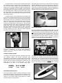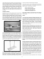
1
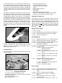
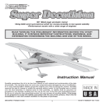
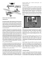
particular assembly step or sequence, do not guess - find
qualified help and use it.
R
RADIO EQUIPMENT:
The RASCAL FORTY ARF requires a standard 4-channel radio
system and five standard servos. We have used and can highly
recommend both the Airtronics™‚ RD-6000 Sport system and the
Hitec™ Flash 4X system. Both of these very affordable and
reliable radio systems offer all the features you’ll need for this and
the many other R/C aircraft in your future. For reference, this
assembly manual shows the installation of the Airtronics™‚
RD-6000 Sport radio system with Airtronics™‚ #94102 standard
servos. In addition, you will need two aileron 24” servo lead
extensions and an aileron servo Y-harness for connection to the
receiver.
RASCAL FORTY ARF ASSEMBLY MANUAL
INTRODUCTION:
SIG’s RASCAL FORTY ARF represents the classic good looks
and lines of yesterday’s private aircraft designs with performance
that meets and even exceeds today’s standards. The RASCAL
FORTY is unlike any .40 size high-wing design available and offers
flight characteristics that are equally unusual for such aircraft. The
airplane is not just easy to fly, it’s almost immediately “comfortable”
to most R/C pilots. The look is decidedly from the “Golden Era” of
aviation and yet the RASCAL FORTY ARF looks right at home on
any modern flight line!
ENGINE SELECTION:
The RASCAL FORTY ARF has a lot more going for it than just its
good looks. Its performance is as remarkable as its appearance.
High speed is impressive and low speed is awesome and what
goes on in between is just about as much fun as you can handle.
The RASCAL FORTY could easily fill the role of a trainer and then
be flown as your second airplane. Set the control throws at the
suggested beginning movements, throttle back and learn to fly
with a truly honest, gentle airplane. When you get through basic
training and comfortable with the requisite take-offs, landings, and
basic flight maneuvers, dial-up the control throws a little to enjoy a
very aerobatic airplane. Inside and outside loops, rolls, inverted
flight, snap maneuvers, great spins, and even knife-edge flight are
all in the RASCAL FORTY flight envelope. Landings and take-offs
are just about the smoothest you’ll ever experience, even when
compared to tricycle landing gear equipped aircraft. As the saying
goes, “real pilots fly tail-draggers”.
Engine choices for the RASCAL FORTY ARF are many. Keep in
mind that the airplane has been designed to be light, producing a
very favorable wing loading. The design is also relatively
aerodynamically clean. These two factors result in great
performance when using the recommended engine sizes. Overpowering this model is totally unnecessary and not at all
recommended.
We’ve found that the RASCAL FORTY ARF really comes into
its own when flown with 4-stroke engines in the .40 - .52
displacement range. We’ve test flown the RASCAL FORTY with
virtually every available 4-stroke engine in this range with
outstanding results. The airplane just seems to fly wonderfully with
4-stroke engines. It just looks and sounds “right” with a 4-stroke in
the nose.
2-stroke engines also fly this airplane very nicely. Any plainbearing or bearing equipped .36, .40, or .46 sport engine would be
a good choice. For example, a great choice would be the Irvine .40
engine. Like all Irvine engines, the .40 is powerful, reliable, and
quiet. Whatever engine you choose, take the time to carefully
break it in according to the manufacturer’s instructions. A good
running, reliable engine is a minimum requirement for the
enjoyment of this or any R/C model aircraft.
The RASCAL FORTY ARF kit has been engineered to get you into
the air quickly as possible with an R/C model that will truly last.
The airframe has been expertly built and covered with AeroKote™.
This material is both rugged and easy to repair. The covering trim
scheme is totally unique and also offers good visibility and
orientation in the air. The two-piece wing allows convenient
transportation in the smallest of vehicles.
This assembly manual has been specifically sequenced to get
your RASCAL FORTY ARF assembled and into the air very
quickly. We strongly suggest that you read through the manual first
to get familiar with the various parts and their assembly
sequences. The proper assembly and flying of this aircraft is your
responsibility. If you are new to the sport/hobby of radio control,
we urge you to seek the assistance of a qualified person to help
you assemble this model airplane. If you do not understand a
COVERING MATERIAL:
Your RASCAL FORTY ARF has been professionally covered using
AeroKote™. This material is well known for its ease of application,
light weight, and consistency of color. If you live in a dry climate,
you may notice that some wrinkles might develop after removing
the covered parts from their plastic bags. This is perfectly normal
1
in low humidity climates. Your model was built and covered in a
part of the world with relatively high humidity and therefore the
wood was likely carrying a fair amount of moisture. When exposed
to drier air, the wood typically loses this moisture, dimensionally
“shrinking” in the process. In turn, this may cause some wrinkles.
However, wrinkles are easy to remove by just using a hobby type
heat iron.
Small Allen Wrench Assortment
Pin Vise for Small Dia. Drill Bits
Hobby Knife With Sharp #11 Blades
Scissors
Heat Iron and Trim Seal Tool
Masking Tape
Paper Towels
Small Power Drill With Selection of Bits
Dremel® Tool With Selection of Sanding and Grinding Bits
A soldering iron and solder may also be required.
We suggest covering the iron’s shoe with a thin cotton cloth, such
as an old T-shirt, to prevent scratching the film. The iron should be
set to about 220O - 250O F, (104O F - 121O C). Use the heated iron
to lightly shrink the material - do not press on it. Then lightly iron
the material back down to the wood. You can also use a hobbytype heat gun to re-shrink the covering but you must be careful
around seams or color joints. Re-heating seams may cause them
to “creep”, making them unsightly. This is especially true with the
RASCAL FORTY inset trim scheme. You must also be careful
when using a heat iron or heat gun when working around the
windshield and side windows - heat will distort this clear plastic
material.
COMPLETE KIT PARTS LIST:
The following is a complete list of all parts contained in this kit.
Before beginning assembly, we suggest that you take the time to
inventory the parts in your kit. Note that the hinges for the rudder
and fin are in place in the bag containing these two parts. The
rudder/fin hinges are not glued in place yet. Please note that the
nuts and bolts required to mount your engine to the aluminum
motor mounts are not included in this kit and must be purchased
separately.
BASIC AIRCRAFT PARTS:
❑
❑
❑
❑
1
1
1
1
each
each
each
each
Fuselage
Wing Panel Set, Ailerons Installed and Pre-Hinged
Horizontal Stabilizer & Elevator Set, Pre-Hinged
Vertical Fin & Rudder Set
SUB ASSEMBLIES:
❑
❑
❑
❑
Fiberglass Wheel Pants, 1 Left, 1 Right, Pre-Painted
Hardened Aluminum Landing Gear, Pre-Drilled
2-3/4” Dia. Main Wheels - “Lite”-type With Plastic Hubs
2-1/2” Dia. SIG Spinner Assembly, White,
With Adapters & Hardware
❑ 1 each Fuel Tank Assembly, 260cc (8.8 oz.) With All Fittings
❑ 1 each Tailwheel Assembly:
❑ 1 each Aluminum Tail Wheel Bracket,
With Wheel Assembly
❑ 2 each Centering Springs
❑ 2 each #2 x 10mm (3/8”) Phillips/Washer Head
Screws
❑ 3 each #4 x 10mm (3/8”) Phillips/Washer Head
Screws
❑ 1 each Aluminum Control Horn For Centering
Springs
❑ 1 set
Adjustable Aluminum Motor Mount Assembly:
❑ 2 each Aluminum Mounting Plates 1/8” x 7/16” x 2-3/4”
❑ 4 each M3 x 20mm (3/4”) Phillips Head Bolts
❑ 4 each M3 Washers
❑ 4 each M3 Split Ring Washers
For part number reference, your RASCAL FORTY ARF was
covered in AeroKote™ film with the following part numbers:
#SIGSTL100 White and #SIGSTL010 Transparent Red or
#SIGSTL050 Transparent Blue.
REQUIRED TOOLS:
For proper assembly, we suggest you have the following tools and
materials available:
1
1
2
1
set
each
each
each
PLASTIC PARTS:
❑ 1 set
Molded Clear Plastic Left & Right Side Windows
❑ 2 each White Plastic Aileron Hatch/Servo Mounts - 1 Left,
1 Right
❑ 2 each #10-32 x 1” Slotted Head Nylon Wing Bolts
❑ 4 each Nylon Control Horns - Ailerons - 2, Elevators - 1,
Rudder - 1
❑ 2 each Inner Nylon Rudder & Elevator Pushrod Tubes 1/8” Dia. x 25-3/4”
❑ 1 each Inner Nylon Throttle Pushrod Tube - 1/8” Dia. x 16”
A selection of glues - SIG Thin and Thick CA and
SIG Kwik-Set 5-Minute Epoxy
Clear Dope For Fuel-Proofing Engine Cut-Outs
Threadlock Compound, Such as Loctite® Non-Permanent Blue
Screwdriver Assortment
Pliers - Needle Nose & Flat Nose
Diagonal Wire Cutters
2
For the following steps you will need two standard aileron servos,
two 24” servo extensions and a Dual Servo “Y” Harness for your
particular radio system.
HARDWARE:
❑ 4 each #2 x 6mm (1/4”) Phillips/Washer Head Screws Aileron Mounting Block Attachment
❑ 8 each #2 x 8mm (5/16”) Phillips/Washer Head Screws Aileron Hatch Mounting
❑ 8 each M2 x 20mm (3/4”) Phillips Head Bolts Control Horn Mounting, 2 Per Horn
❑ 2 each M4 x 40mm (1-9/16”) Phillips/Washer Head Axle
Bolts - Main Wheel Axles
❑ 4 each M4 Lock Nuts - Wheel/Wheel Pant Attachment
❑ 4 each M4 x 20mm (3/4”) Phillips/Washer Head Bolts Main Landing Gear Attachment
❑ 4 each M4 Split Ring Washers - Main Landing Gear
Attachment
❑ 4 each M3 x 10mm (3/8”) Phillips Head Bolts - Wheel Pant
Attachment
❑ 4 each M3 Split Ring Washers - Wheel Pant Attachment
❑ 8 each Threaded Metal Control Links - Throttle - 2,
Rudder - 2, Elevator - 2, Ailerons - 2
❑ 6 each M2 x 22mm (7/8”) Threaded Studs For Clevises
❑ 1 each Hardened Aluminum Blade Wing Joiner 3mm (1/8”) x 21/32” x 12-1/16”
❑ 1 each Rear Wing Locating Pin, Steel - 3/16” dia. x 2-3/8”
❑ 2 each Aileron Pushrods, Threaded One-End
With “Z-Bends” - .070” x 3-1/8”
❑ 1 each 10” Metal Pushrod, Threaded One-End
(4-Stroke Throttle Linkage Only)
❑ 1 each Solder Link (4-Stroke Throttle Linkage Only)
❑ 1) The aileron servo bay for each wing panel is located on the
bottom surface, just in front of the aileron. These bays have been
covered over and now need to be opened to allow access. Use a
hobby knife to make four diagonal cuts from each corner of the
servo bay, meeting in the middle.
MISCELLANEOUS:
❑ 4 each Hardwood Aileron Servo Mounting Blocks,
5/16” x 1/2” x 7/8”
❑ 1 each Fuel Tank Retainer - 5/16” x 3/4” x 3-3/16” Balsa
❑ 1 each Assembly Manual
❑ 1 each Decal Set, 6-3/4” x 20”
Use a covering iron to seal the four loose edges of each side of the
servo bay opening and trim the excess covering material with a
hobby knife. Inside the servo bay opening you will find a short
length of wood with a string tied to it. This string is used to pull the
aileron servo lead through the wing and out of the opening in the
bottom of each wing panel - leave it in place for now.
WINGS:
The wings have designed and made to be a 2-piece system, joined
by the main aluminum blade joiner at the spar box location and a
steel locating pin at the rear. This system has proven to be very
tough and easy to use. An obvious benefit is the fact that the wing
panels can be easily transported or stored, requiring a minimum of
space. Also, you might want to consider using 5-minute epoxy to
permanently install the aluminum blade wing joiner and the rear
steel locating pin into one of the wing panels. Doing this prevents
accidentally losing these parts - your call. Note that the ailerons
have been factory-hinged. Flex them up and down a few times to
loosen them up and they are ready to use. Last, to avoid
unnecessary dents, dings, or scuffing of the various covered parts,
we suggest that you cover your workbench with a protective
blanket or foam sheet.
Also, on the bottom of each wing panel, at the center front location,
you will see an oblong opening. This is the servo lead exit
opening. Inside this opening you will see a piece of wood with a
string tied to it - this is the other end of the string in the aileron
servo bay. Leave the string in place for now.
3
❑ 2) The aileron servos are now mounted to the molded plastic
servo hatch covers. Begin by installing the rubber grommets and
brass eyelets, (supplied with your radio system), into each servo.
Use epoxy to mount the hardwood blocks to the inside surface of
the hatch cover, using the servo for spacing. Be sure to locate the
servo with the output arm directly over the center of the molded
aileron pushrod fairing as shown. Allow the epoxy to cure.
❑ 4) Plug a 24” servo extension lead into each servo plug and
secure the connection with plastic tape. Reach into the aileron
servo bay and pull the small piece of wood with the attached string
out of the opening. Remove the wood piece and securely tie the
end of the string onto the end of the servo lead extension. From
the inboard oblong opening near the center section of the wing
panel, reach in and remove the piece of wood with the string tied
to it - tweezers or needle nose pliers are handy for this. Lightly pull
on the string to route the servo lead cable through the wing and
out through the oblong center section opening. Pull the servo lead
fully out of the exit hole, leaving no slack in the aileron servo bay.
With the mounting blocks now positioned and glued in place,
remove the servo. Use a a Dremel® Tool and a tapered sanding
drum bit to open the ends of the plastic aileron pushrod fairings
where the pushrod passes through from the servo arm to the
aileron horn.
❑ 5) Carefully fit the plastic aileron servo tray, with the servo
mounted, into the aileron servo bay. Since it is easily viewed
through the top of the wing, align the servo accurately within the
wing. Use pieces of masking tape to hold the servo tray in final
position. Using the pre-drilled mounting holes in the servo tray as
a guide, drill four 1/32” dia. guide holes through the sheeting in the
bottom of the wing. Mount the servo tray using the provided
#2 x 5/16” Phillips/Washer Head self-tapping screws. Mount the
remaining servo tray into the remaining wing panel in the same
manner. Because the servo tray will have to be removed briefly in
the next few steps, remove the screws and set them aside for now.
With the two servo trays now prepared, use the mounting screws
provided with your radio system to secure the aileron servos to the
mounting blocks. We suggest drilling small pilot holes first to avoid
splitting the blocks.
❑ 3) The final preparation step for the servo trays is to drill two
1/32” diameter holes in each servo tray, one directly beneath both
hardwood servo mounting blocks, as shown. Use the four #2 x 6mm
self-tapping screws provided to secure the mounting blocks.
4
❑ 6) From the kit contents locate two nylon control horns, four
M2 x 3/4” Phillips Head bolts and two wire aileron pushrods
(threaded at one end, “Z”-bend at the other end).
molded fairing in the servo tray, at 90O to the servo. Take off and
reposition the output arm as needed to achieve this. With these
two issues addressed, install and tighten the servo output arm
screws in both servos. Carefully re-install the servo and tray back
into the aileron servo bay opening in the wing panel and secure it
in place with four #2 x 5/16” Phillips/Washer Head screws. Use a
couple of pieces of masking tape to hold the aileron in neutral.
❑ 7) Use a razor blade to remove the molded nylon mounting
base from the back of the control horn. Attach the metal control
link to one of the nylon control horns. With the wing panel upside
down on the workbench, thread the control link on the pushrod as
needed to position the base of the control horn at the leading edge
of the aileron. Visually line-up the pushrod with the wing ribs, so
that it is exiting straight out of the servo tray fairing. With these
elements now in position, use a pencil to mark the two holes in the
control horn base onto the aileron. Remove the control horn from
the metal control link.
You will also need the aileron servo output arms that you intend to
use. We like using the 4-arm type, choosing the arm with the
longest length. You will likely have to use a small drill to open the
holes in the servo arm in order to accept the .070” dia. pushrod
wire. Slip the “Z”-bend end of the wire pushrod into the outer hole
in the output arm and press the output arm onto the servo with the
arm facing 90O down into the fairing molding on the servo tray, as
shown (this is the ideal “neutral” position for the servo with the
radio system on). Thread the metal control link onto the aileron
pushrod about halfway, allowing an equal amount of adjustment in
either direction.
At one of the marks just made, drill a 3/32” dia. hole all the way
through the aileron, perpendicular to the bottom surface. Slip a
M2 x 3/4” bolt through the appropriate hole in the nylon control
horn and push the bolt through the aileron. Position the horn and
drill the remaining bolt hole, again perpendicular to the bottom
surface of the aileron. Thread another M2 x 3/4” bolt through the
nylon horn base and the aileron. Adjust the drilled holes as
needed to line-up with the holes in the nylon mounting base. Align
the holes in the base with the tips of the bolts protruding from the
top of the aileron. With a small Phillips screwdriver, thread the
bolts into the holes in the mounting base, securing the horn to the
aileron - do not over-tighten the bolts. Repeat this procedure with
the remaining wing panel. Use diagonal cutters to remove the
exposed tips of the bolts on top of the nylon base and file them
smooth. Connect the control links to the control horns.
With the servos accessible, now is the time to check their
movement and centering with your radio system. Connect the
servo leads to the Y-harness and plug it into the correct aileron
receptacle in your receiver. Connect the battery and turn the
system on. First check for the correct direction of travel. Reverse
the servo direction on your transmitter if necessary. Next, check
the centering of the servo arms, with the trim lever in neutral.
Remember that the output arm should be facing directly into the
FUEL TANK ASSEMBLY:
The 260cc (8.8oz.) fuel tank supplied with this kit is now
5
assembled. We suggest using a simple two-line fuel system in this
airplane. One fuel line is connected to the fuel pick-up or “clunk”
line and the engine’s carburetor. This same line is then used to fill
the tank (if you are not using a fueling valve system). The second
fuel line is the overflow line for use when filling the tank. After filling
the tank this same fuel line is then connected to the engine’s
muffler pressure nipple to provide manifold pressure to the tank.
Note that the rubber stopper for the tank has two holes all the way
through it. Use these two holes for the two aluminum fuel lines.
possible. To do this we installed a Du-Bro #334 Kwik-Fill Fueling
Valve onto the firewall in the engine compartment.
To mount the fueling valve, we made a simple 90O “L” bracket from
a 3/4” wide strip of K & S .060 aluminum sheet. This bracket, with
the valve in place, was then attached to the firewall using a couple
of #2 x 3/8” socket head sheet metal screws.
If you choose to mount the valve in the side position, as we did for
our 2-stroke engine, then a smooth, round hole must be made in
the side of the fuselage. This hole must be directly over the center
of the fuel valve to allow the fuel probe to be inserted into the valve
for filling and emptying the tank. Note that this valve can also be
mounted with its face pointing straight down, as we did in the
4-Stroke Engine Installation. Mounted in this position, the need for
a hole in the side of the fuselage is eliminated. The nice thing
about this fueling system is its convenience, simplicity, and the fact
that it only requires the two basic fuel lines to function. If you wish,
a third fuel line can be used for fueling and de-fueling purposes.
This dedicated third fuel fill line requires a second “clunk” fuel
pick-up line inside the tank. The new Du-Bro #840 “Fill-It” product
would be a good choice for this type of fuel tank set-up.
Gently bend the aluminum overflow tube upward to just reach (but
not touch) the top of the tank. Adjust the length of the internal
silicon fuel tubing to allow free movement of the fuel pick-up weight
inside the tank. Insert the stopper assembly into the neck of the
tank and secure it by tightening the compression bolt in the center
of the stopper assembly. Slip short lengths of silicon fuel tubing
over the aluminum fuel lines and identify each as “vent” and “carb”
with small pieces of tape. This helps later when connecting the
fuel lines to their proper locations. It is more convenient to install
the fuel tank after engine installation.
ENGINE AND FUEL TANK INSTALLATION:
This phase of assembly requires some custom installation work,
based on the particular engine you’ve chosen for your Rascal
Forty, (note that both right and down thrust adjustments are
pre-built into this airplane). The following engine installation
instructions have been separated into two general engine types typical .40 - .46 2-strokes and typical .40 - .52 4-strokes.
The basic design of the RASCAL FORTY calls for mounting the
engine inverted in the nose. Over the years there have been
stories about inverted engines and how they run, primarily having
to do with “flooding”. In our considerable experience with this
airplane and with running engines mounted in the inverted
position, we’ve found that both two and four-stroke engines work
perfectly fine in the inverted position, with no more tendency to
“flood” than engines mounted in other positions. Many, many
model aircraft designs use engines mounted in the inverted
position. The difference can generally be found in the starting
procedures used by individual modelers.
OPTIONAL:
Because of the inverted position of the engine in this design, we
wanted to make the fueling and de-fueling process as simple as
Flooding is caused by an unwanted siphon effect from the fuel tank
to the engine’s carburetor. Note that the position of the fuel tank in
this design has taken this into consideration. However, siphoning
can be minimized by remembering to keep the carburetor closed
between flights. If you are using the Du-Bro #334 Fueling Valve,
siphoning can be totally eliminated by inserting the filler probe into
the valve between flights. Doing this closes the fuel line to the
carburetor completely. When first starting the engine, keep the
6
throttle in the low position. Allow muffler manifold pressure from
the tank vent line to get fuel to the carburetor. Avoid “choking” fuel
through the line by placing your finger over the carburetor. With
properly broken-in engines, these procedures should work
perfectly every time.
2-STROKE ENGINES:
If you plan to use a 2-stroke engine, some basic openings in the
nose of the fuselage must be made to allow for muffler clearance
and mounting, as well as an exit hole for the needle valve. In
addition, if you plan to use a fuel filler valve, such as the Du-Bro
#334 Kwik-Fill Fueling Valve or some other type of fueling system,
this will be the time to install it. For reference, the engine shown in
the following assembly and installation steps is the Irvine .46,
typical of engines in the .40 class.
❑ 3) Use alcohol or acetone to clean the bottom surfaces of the
engine mounting lugs, removing any oil or grease. Do the same
thing to the tops of the aluminum motor mounts, cleaning them
completely. Apply 3 or 4 drops of thin CA glue to the bottom of
each mounting lug on the engine. Carefully place the engine
back into the nose of the airplane, positioning it with the proper
1/16” - 3/32” clearance for the spinner backplate. Hold the engine
in place to the aluminum rails and use a little accelerator to set the
CA glue.
The fuselage has the throttle pushrod housing tube already
installed. However, this tube has not been glued in place and is
removable. The firewall has been pre-drilled for installing the
throttle tube on either side of the firewall. This allows for the
different locations of various engine throttle arms, including
4-strokes. Before starting the engine installation, be sure the
throttle pushrod tubing is on the correct side of the firewall for your
particular engine. The remaining hole in the firewall can be filled
with a short piece of rounded balsa, sanded smooth and fuelproofed with thin CA, dope or epoxy resin.
❑ 4) Loosen and remove the four bolts holding the aluminum
rails in place and carefully remove the engine, with the attached
aluminum rails, from the nose of the model.
❑ 1) With the fuselage upside down on your workbench,
temporarily install the two aluminum motor mount rails onto the left
and right hardwood motor mount bearers in the nose of the
fuselage. Align the oblong holes over the pre-drilled bolt holes and
insert the four M3 x 20mm bolts with the large washers only (the
lock washers will only be used when the engine is final-mounted)
through the aluminum mount holes. Use a screwdriver to thread
the bolts in place but do not tighten them. The aluminum rails
should be just free enough to move.
❑ 5) Use a shortened pencil with a sharp point to mark the
locations of the engines mounting holes onto the aluminum motor
mounts. To remember which rail fits on the right and left side of the
engine, mark them with an “R” and “L” (left and right).
❑ 2) With the muffler and needle valve removed, fit your engine
in place between the aluminum rails, with its mounting lugs on top
of the rails. Slide the engine into its approximate mounting position
with the prop hub just ahead of the front of the fuselage by
approximately 1/16” - 3/32”. This spacing will be the clearance for
the spinner backplate (temporarily mounting the spinner backplate
to the engine and using 1/16” scrap balsa “spacers” makes this
spacing easy and accurate). Be sure the aluminum motor mount
rails are against the sides of the engine case and the engine is
centered at the front. With the engine and aluminum mounts now
in position, lightly tighten the four motor mount bolts to hold the
aluminum rails in place. Remove the engine.
Tap the aluminum mounts to free them from the engine. Use the
pencil marks to drill clearance holes through both motor mounts
for the engine mounting bolts (not supplied). If you use typical
6-32 socket head bolts for mounting the engine, the holes should
7
be made with a 9/64” dia. drill bit.
pair of pliers transfer the marks to the outside of the fuselage. Grip
the pin tightly with the pliers, align the pin with the marks on the
inside of the engine compartment and push it through the fuselage
side and covering. This now shows you where to begin the holes.
Use a Dremel® Tool and grinding bit to begin opening the muffler
exit hole, a little a time. Re-install the engine periodically to check
the proper alignment of your work.
The final muffler opening should leave about 1/16” clearance
around its outer surface. The edges of the opening should be
sanded smooth. To make the needle valve exit, begin with a small
drilled hole. With the engine in place, the hole should be opened
progressively, centering it exactly with the carb. The diameter of
the hole should be just a little larger than the diameter of the
needle valve body. Note that with some engines, it may be
necessary to make a music wire extension. Most engine
manufacturers have holes and set-screws in their needle valve
assemblies for this purpose.
❑ 6) Use the mounting hardware to now secure the engine in
place to the aluminum rails. We used and recommend 6-32 lock
nuts to secure the bolts. Note that in order to fit without
interference, the threaded length of the mounting bolts must be
trimmed to no longer than 9/16”. Re-install the engine - mounted
on the aluminum rails - back into the nose of the model and
temporarily secure the rails with the four M3 x 20mm bolts.
With the engine in place in the nose, mount the muffler and needle
valve to check for final clearance and make any final adjustments
that might be needed.
Basically, the engine is now correctly positioned and ready for final
mounting. What remains is to accurately locate and open the
required clearance holes for the engines’ muffler, needle valve and
any other needed openings, such as a clearance hole for the fuel
filler valve, described earlier. To neatly create these openings, use
a Dremel® Tool and various sanding and grinding bits, a drill with
various bits, some sandpaper, a hobby knife and a sharp pencil or
non-permanent marker pen.
❑ 7) Use a pencil to mark the approximate location of the muffler
manifold onto the inside surface of the engine compartment,
where it will exit. Likewise, mark the approximate location of the
engine’s needle valve. Remove the engine and aluminum motor
mounts. With the engine out of the way, use a straight pin and a
❑ 8) If you are using the optional fueling valve, now is the time to
8
mount it and make the required hole in the side of the fuselage for
the fueling probe. Locate the aluminum bracket to the firewall,
(with the fuel valve in place), and mark the approximate location of
the required opening in the fuselage side. Like the needle valve
opening, start with a small drilled hole and open it up to match the
center of the fueling valve.
❑ 9) The engine compartment was fuel-proofed at the factory.
However, the exposed wood edges of the muffler and needle valve
openings should now be coated to make them fuel proof as well.
We suggest using clear dope or epoxy resin to seal the exposed
wood. To make the job look totally complete and custom, try using
flat white or flat black dope or other fuel-proof paint.
❑ 10) The fuel tank can now be installed. Apply a bead of silicon
sealer around the neck of the tank and install it into the fuel tank
compartment, through the top of the fuselage. Press the neck into
the hole in the firewall. Included in the kit contents is a balsa piece
measuring 5/16” x 3/4” x 3-3/16”. This is used to hold the fuel tank
in place at the rear. Position the balsa retainer directly behind the
tank, between the fuselage sides. Apply a couple of drops of thin
CA glue to each side of the balsa piece to hold it in place. If for
any reason you need to remove the tank, the balsa piece can be
easily popped loose and tank removed.
As mentioned in the 2-stroke instructions, the fuselage comes with
the throttle pushrod housing tube installed, but not yet glued in
place. The firewall has already been pre-drilled to allow installing
this tube on either side. Before starting the engine installation, be
sure the throttle pushrod tubing is on the correct side of the firewall
for your particular engine. The unused hole can be filled with a
short piece of dowel and sanded smooth. It should then be fuelproofed with thin CA, dope or epoxy resin.
❑ 1) Place the fuselage upside down on your workbench and
temporarily install the two aluminum motor mount rails onto the
hardwood motor mount bearers built-in to the nose of the fuselage.
Align the oblong holes in the aluminum rails over the pre-drilled
holes in the wood bearers and insert the four M3 x 20mm bolts
with the larger washers only (the lock washers will only be used
when the engine is final-mounted) through the aluminum mount
holes. Use a screwdriver to thread the bolts in place but do not
tighten them. Leave the aluminum rails just free enough to move.
❑ 11) Apply a little thread-locking compound to the threads of the
M3 x 20mm mounting bolts. Install the lock washers onto each
bolt, followed by the larger flat washers. Install the engine and
aluminum rails into the engine compartment. Slip the four bolts
(with washers) into the oblong holes in the aluminum rails. Thread
the bolts into their blind mounting nuts and tighten the bolts firmly
to the wood motor mounts - be sure to maintain the 1/16” - 3/32”
spinner backplate clearance. Use medium fuel tubing (not
supplied) to now make the required connections between the
engine and fuel tank and the vent line and muffler manifold
pressure nipple.
❑ 2) Remove the muffler header pipe and needle valve from the
engine. Fit the engine in place onto the aluminum rails. Slide the
engine to its approximate mounting position with the prop hub just
ahead of the front of the fuselage by approximately 1/16” - 3/32”.
This spacing will be the clearance for the spinner backplate
The throttle linkage will be made during the radio installation
phase of these instructions. This completes the engine and fuel
tank installation.
4-STROKE ENGINES:
Installing the typical .40 - .52 4-stroke engine is similar to installing
2-stroke engines. However, there are obvious physical differences
in the basic configurations of these engines, including totally
different carburetor, throttle arm, and muffler locations. For
reference, the engine shown in the following steps is a Magnum®
XLFS .52AR 4-stroke, (to more easily install this particular engine,
we reversed the carburetor position 180O on the intake manifold).
The engine compartment in the Rascal Forty will accept virtually
any make of 4-stroke engines in .40 to .52 c.i. sizes.
9
(temporarily mounting the spinner backplate to the engine and
using 1/16” scrap balsa “spacers” makes this accurate). Slide the
aluminum motor mount rails against each side of the engine case,
making sure the engine is centered at the front. With the engine
and aluminum mounts in this position, lightly tighten the four motor
mount bolts to hold the aluminum rails in place. Remove the
engine.
❑ 3) Use alcohol or acetone to clean the bottom surfaces of the
engine mounting lugs, removing any oil or grease. Do the same
thing to the tops of the aluminum motor mount rails, (still bolted in
place in the nose). Apply 3 or 4 small drops of thin CA glue to the
bottom of each mounting lug on the engine. Carefully place the
engine back into the nose of the airplane, positioning it with the
proper 1/16” - 3/32” clearance for the spinner backplate. Hold the
engine in place to the aluminum rails and use a little accelerator to
set the CA glue.
The engine is now basically in place, ready for final mounting.
What remains is to accurately locate and open the required
clearance holes for the engine’s manifold/muffler pipe, needle
valve and any other required openings for your particular engine.
❑ 4) Loosen and remove the four bolts holding the aluminum
rails in place and carefully remove the engine and aluminum rails
from the nose of the model.
❑ 7) Use a non-permanent marker pen to mark the approximate
position of the muffler manifold pipe onto the bottom surface of the
fuselage, where it will exit. Likewise, use a pencil to mark the
approximately centered location of the engines’ needle valve onto
the inside surface of the engine compartment. Remove the engine
and aluminum motor mounts.
❑ 5) Use a shortened pencil with a sharp point to mark the
locations of the engines mounting holes onto the aluminum motor
mounts. Tap the aluminum mounting rails to remove them from the
engine. Use the pencil marks to drill clearance holes through both
motor mounts for the engine mounting bolts (not supplied). When
using typical 6-32 socket head bolts for mounting the engine, these
holes should be made with a 9/64” dia. drill bit.
Use a Dremel® Tool and drum sanding bit to open a small, halfround opening in the side of the fuselage to allow clearance for the
engine’s manifold pipe. Leave about 3/32” clearance around the
surface of the pipe. Sand the edges of this opening smooth.
❑ 6) Use your mounting hardware to now secure the engine in
place to the aluminum rails. We used and recommend 6-32 socket
head bolts and lock nuts for this purpose. Note that in order to fit
without interference, the threaded length of the mounting bolts
must be trimmed to no longer than 9/16”. Re-install the engine mounted on the aluminum rails - back into the nose of the model
and temporarily secure the rails with the four M3 x 20mm bolts.
To make the needle valve exit hole, begin by using a pair of pliers
and a sharp pin. Grip the pin tightly with the pliers and push the
pin through the fuselage, at the needle valve mark made earlier.
This discloses the location of the mark on the outside of the
fuselage. Drill a 1/8” dia. hole through the pin hole. Put the engine
in back in place and check the position of the hole with the needle
valve opening in the carburetor. Adjust the hole to center it exactly
10
and progressively enlarge it to accept the needle valve body
through the fuselage and into the carburetor. The finished hole
should be just a little larger than the diameter of the needle valve
body.
the factory. However, the exposed wood edges of the muffler and
needle valve openings should now be coated to make them fuel
proof as well. We suggest using clear dope or epoxy resin to seal
the exposed wood. To make this job look totally complete and
custom, try using flat white or flat black dope or other fuel-proof
paint.
With the engine in place in the nose, install the manifold pipe and
the muffler to check for the final fit. Install the needle valve into the
carburetor. Make any final adjustments to these openings. You will
likely need to add a wire needle valve extension to clear the
fuselage side. The needle valve will have a hole in its center with
a setscrew for this purpose. Use the engine manufacturer’s
included needle valve extension wire (the Magnum .52 did not
include one) or make one from 1/16” dia. music wire.
❑ 10) The fuel tank is now installed. Apply a bead of silicon
sealer around the neck of the tank and install it into the fuel tank
compartment, through the top of the fuselage. Press the neck into
the hole in the firewall. Included in the kit contents is a balsa piece
measuring 5/16” x 3/4” x 3-3/16”. This is the rear tank retainer.
Position the retainer directly behind the tank, between the fuselage
sides. Apply a couple of drops of thin CA glue to each side of the
retainer to hold it in place. Should you ever need to remove tank,
the retainer can be easily popped loose and the tank can be
removed.
❑ 8) If you are using the optional fueling valve, now is the time to
mount it. We mounted ours on the left side of the firewall (opposite
the throttle linkage), facing straight down. This works very well and
eliminates the need for another hole in the side of the fuselage for
the fueling probe. Make and install the aluminum mounting
bracket to the firewall (with the fuel valve in place) and mark the
location of the required #2 x 3/8 mounting screws onto the firewall.
Mount the bracket to the firewall.
❑ 11) Apply a little thread-locking compound to the threads of the
3.5 x 20mm mounting bolts. Install the lock washers onto each
bolt, followed by the larger flat washers. Install the engine and
aluminum rails into the engine compartment. Slip the four bolts
(with washers) into the oblong holes in the aluminum rails. Thread
the bolts into their blind mounting nuts and tighten the bolts firmly
❑ 9) The engine compartment has already been fuel-proofed at
11
Last, you will need to remove the covering over the rudder and
elevator pushrod exits. These are located on each side of the
fuselage, beneath the horizontal stabilizer. A sharp #11 blade is
perfect for this step. If necessary, use a covering iron to re-seal the
covering around these openings.
to the wood rail mounts - be sure to maintain the 1/16” - 3/32”
spinner backplate clearance. Use medium fuel tubing (not
supplied) to make the required connections between the engine
and fuel tank and the vent line and the muffler manifold pressure
nipple.
The throttle linkage will be made during the radio installation
phase of these instructions. This completes the engine and fuel
tank installation.
SPINNER ASSEMBLY:
Locate the white SIG spinner assembly from the kit contents. This
spinner is easy to install, lends a great look to your finished
RASCAL FORTY ARF and is ready to use with typical APC
propellers for engines in the size range for this model!
Start by choosing the correct adapter ring for your particular
engine. The fit should be firm (not loose) over the engine’s prop
shaft. Slip the spinner backplate onto the prop shaft and onto the
adapter ring. The propeller is installed next using the engine’s
washer and nut to secure it. The spinner cone is now installed over
the prop and into the recess in the backplate. The spinner is then
secured in place using the provided screws. Be sure to snug these
screws firmly in place but do not over-tighten them.
❑ 2) From the kit contents, locate the horizontal stabilizer and
elevator set and the vertical fin and rudder set. Join the wing
panels together and bolt the wing to the fuselage. Set the airplane
on a flat surface that allows you to easily view it from both the
front and rear. Use 5-minute epoxy to glue the horizontal
stabilizer/elevator assembly to the fuselage. Apply glue liberally to
the stabilizer saddle at the top rear of the fuselage. Also apply
glue to the bottom of the stabilizer where it contacts the fuselage.
Carefully center the stabilizer to the fuselage, making sure it is
centered in top view as well as in front and rear view. Use weights
or pins to hold the stabilizer in this aligned position until the epoxy
cures. Wipe off any excess glue with alcohol.
❑ 3) Remove the rudder from the vertical fin, including the three
hinges. The rudder will be hinged later. The vertical fin is now
glued in place to the top of the stabilizer. Begin by trial-fitting the
fin into the slot on the top of the stabilizer. Test the fit, making sure
that the bottom of the fin sits flat and in full contact to the stabilizer.
Trim or sand the bottom of the fin tab until the fin sits fully in place
on top of the stabilizer. Holding the fin in place, use a sharp pencil
to trace around its forward bottom fairing, where it extends forward
of the stabilizer and on to the top of the fuselage. Remove the fin
and use a sharp knife to remove the covering from just inside of
the pencil marks just made.
FUSELAGE AND TAIL GROUP ASSEMBLY:
Note that the elevators have been pre-hinged to the horizontal
stabilizer. Flex the elevators up and down a few times to free their
movement. However, the rudder has not been pre-hinged and will
have to be hinged during the following assembly steps.
❑ 1) The fuselage has been built and covered with a few
openings that now need to be opened up and cleared to complete
assembly. These are the two landing gear bolt holes on the bottom
of the fuselage and the three pre-drilled holes for mounting the
tailwheel assembly, at the bottom rear of the fuselage.
Use 5-minute epoxy to apply glue to the bottom of the vertical fin,
including the tab that fits into the top of the stabilizer. Press the fin
in place into the top of the stabilizer slot and wipe off any excess
glue with alcohol. Use strips of tape and/or pins to align the fin at
90O to the stabilizer. View the airplane from the front, making sure
the fin is perfectly upright and aligned to the stabilizer, wing, and
fuselage without tilting one way or the other. With the fin now held
12
locations for the screw holes and then use a 1/16” drill bit to make
two guide holes into the bottom of the rudder. Secure the horn in
place with the screws.
in position, allow the glue to set.
X
X
X=X
90
X
O
90
O
❑ 6) The rudder is now hinged to the vertical fin and fuselage.
Slide the three CA hinges in place into the pre-slotted rudder,
centering them. Use pins in the center of each hinge to keep them
centered when pressing them into the hinge slots in the vertical fin.
X
When the epoxy has set, remove the wing from the fuselage.
❑ 4) From the kit contents, locate the bag containing the preassembled SIG tailwheel assembly. Note that the bottom rear of
the fuselage has a plywood hardpoint beneath the covering for
mounting the tailwheel bracket.
Press the rudder hinges in place into the hinge slots in the vertical
fin. Adjust the rudder position to the fin and remove the pins. Use
a piece of masking tape to hold the rudder hard over to one side
or the other, exposing centers of the hinges. Use thin CA glue and
apply 3 - 4 drops to each hinge. Remove the tape and use it to
hold the rudder hard over to the opposite side and again apply
3 - 4 drops of CA glue to each hinge. Remove the tape, center the
rudder by hand and allow at least 10 minutes for the CA glue to
fully wick into and set each hinge. Flex the rudder back and forth
to free its movement. The rudder is now hinged in place.
Mount the bracket to the bottom rear of the fuselage, using three
#4 x 1/2” screws provided. Snug the screws securely.
❑ 5) Attach the aluminum spring centering horn to the bottom
leading edge of the rudder, as shown, using two #2 x 3/8” screws.
Note that the bottom leading edge of the rudder has hardwood
beneath the covering as a hardpoint for the screws. Position the
front edge of the horn 1/8” behind the leading edge of the rudder.
Use the aluminum centering horn to first mark the required
NOTE: The two tailwheel centering springs are not attached until
after the rudder servo has been installed, tested and centered.
❑ 7) From the kit contents, locate the following parts: Formed
13
Aluminum Landing Gear, Fiberglass Wheel Pants, 2-3/4” Diameter
Main Wheels and the following hardware:
in place, use two M3 x 10mm (3/8”) bolts with M3 split ring
washers to secure the pant to the landing gear leg. Check the
wheel for free rotation. Repeat this procedure with the remaining
wheel pant.
2 each M4 x 40mm (1-9/16”) Phillips/Washer Head Axle Bolts
4 each M4 Lock Nuts For Axle Bolts
2 each M4 x 20mm (3/4”) Phillips/Washer Head Bolts Landing Gear Attachment
2 each M4 Split Ring Washers - Landing Gear Attachment
4 each M3 x 10mm (3/8”) Phillips/Washer Head Bolts Wheel Pant Attachment
4 each M3 Split Ring Washers - Wheel Pant Attachment
We also suggest using thread-locking compound when
assembling the wheel pants to the landing gear and the landing
gear to the fuselage.
c.) The completed landing gear is now mounted to the
fuselage using two M4 x 20mm bolts (3/4”) and split ring washers.
Be sure to use a little thread-locking compound on the threads and
snug the bolts in place firmly.
a.) Slip a M4 x 4mm axle bolt through the center of the wheel.
Thread a M4 lock nut onto the threaded end of the axle bolt up to
the hub, leaving just a little “play” to allow the wheel to rotate freely.
Slip the threaded end of the axle bolt through the bottom hole in
the aluminum landing gear and thread another M4 lock nut onto
the axle threads. Tighten the lock nut up to the landing gear.
Repeat the procedure with the remaining wheel. The wheels are
now mounted to the landing gear and ready for the attachment of
the wheel pants. (Note that we cut off the excess bolt material
outside of the lock nut, using a carbide cut-off wheel.)
RADIO INSTALLATION:
Because the aileron servos are already installed and ready to use,
the rest of the radio installation consists of simply mounting the
elevator, rudder, and throttle servos in place and locating the
receiver, battery pack and switch. The pushrod connections to the
servos will be made shortly. Install the rubber grommets and
eyelets supplied with your radio system onto each servo. Install
each servo into its appropriate opening in the servo tray, routing
the leads out from beneath the tray into the main cabin area. It can
be handy to label the servo leads to identify them.
Looking down on the fuselage, as if you were seated in the cabin,
with the servos behind you, the elevator servo fits in the right rear
b.) Note that there is a front and rear edge to the aluminum
landing gear. Facing toward the front of the airplane, the landing
gear legs are canted slightly forward. Be sure to mount the landing
gear and the self-aligning wheel pants in the correct direction!
Slip the wheel pant over the top of the wheel and slide it down in
place over the wheel and onto the inner M4 lock nut. Doing this
should line-up the holes in the aluminum landing gear with the
holes in the wheel pant. If you encounter difficulty in sliding the
pant into place, check the alignment of the inner lock nut and shift
its position as needed to accept the slot in the pant. With the pant
14
servo opening. The rudder servo fits into the left rear servo
opening and the throttle servo fits into the forward opening.
Position the throttle servo with its output arm on the correct side
for connecting to the throttle pushrod. Use the mounting screws
provided with your radio system to mount the servos in place to the
servo tray.
tailwheel bracket. We made a simple wire hook from a straight pin
and attached it to the forward screw holding the bracket in place.
We then used a rubber band to anchor the antenna along the
bottom length of the fuselage.
For now, leave the battery pack loose. When you check for the
correct Center of Gravity in the next few steps, the battery pack will
be positioned as needed. At that time it can be wrapped in foam
and placed in the fuselage.
The on/off switch can be mounted wherever it is most convenient
- typically this is on the left side of the fuselage. If you want the
switch in this location, you will need to cut a small rectangular slot
for the switch in the fuselage side. Then, just mount the switch with
the hardware supplied in your radio system. We prefer to mount
our switches internally and in this design this is fairly easy to do.
We placed the switch on the floor of the fuselage, just behind the
main landing gear mounting block. We drilled the switch lever to
accept a piece of .046 music wire. The wire simply extends out
through the fuselage side with a simple “L” bend. Whatever switch
mounting method you use, always make sure the switch is
securely in place with no pressure on the wiring.
Installation of the pushrods in the following steps requires the use
of your radio system. Therefore you should now prepare the radio
system for this purpose. First, make sure both the airborne and
transmitter batteries are charged. Next, turn the system on and
check the throttle, elevator, and rudder servos for the correct
direction of travel. Using the transmitter, reverse any servo
traveling in the wrong direction. Make sure that the trim levers for
these servos are all in neutral. Last, prepare and mount
the servo output arms onto each servo - do not install the locking
screw at this time. As shown, we prefer using 4-arm output arms,
using the longest arm for the linkage. We also typically cut-off the
remaining, unused arms to avoid clutter. The rudder and elevator
pushrod connections will be made on the outside of these two
servos. Therefore, the servo output arms should be mounted on
the servos with the link holes at 90O to the servo - this is going to
be the “neutral” position for the rudder and elevators. The throttle
servo arm is typically mounted at approximately 45O, allowing
uniform travel in either direction (final adjustments to the throttle
linkage will be made during set-up).
PUSHROD INSTALLATION:
The control pushrod system used in this design is very straightforward. The outer nylon control tube housings have already been
installed in your model. What remains is to make the inner nylon
pushrod connections from the servos to the rudder, elevators, and
throttle. From the kit contents locate the following parts:
With the servos and switch in place, the receiver can now be
placed into the fuselage. Connect the servo leads to the
appropriate channel in the receiver. Also plug the “Y-harness
connector in place into the aileron channel and the switch
connector into the receivers battery receptacle. Wrap the receiver
in protective foam, held in place with rubber bands, tape, etc.
Install the protected receiver into the compartment directly
beneath the servo tray. The “Y-harness” leads should both be left
sticking out of this opening and accessible. Likewise, the receiver
antenna should also be exiting this opening in the fuselage former.
Gently press the receiver in place beneath the servos.
2 each M4 x 40mm (1-9/16”) Phillips/Washer Head Axle Bolts
2 each Inner Nylon Control Tube Rudder and Elevator Pushrods
1 each Inner Nylon Control Tube - Throttle Pushrod
6 each Threaded Metal Control Links
6 each M2 x 7/8” Threaded Control Link Studs
2 each Nylon Control Horns
4 each M2 x 3/4” Phillips Head Bolts Control Horn Attachment
We have found that with this design, the easiest way to route the
antenna out of the fuselage is to make a small hole, (about 1/16”
or so), in the bottom fuselage sheeting, just ahead of the middle
cabin former. To avoid pulling on the antenna at the receiver, fit the
antenna wire with the radio manufacturer’s supplied strain relief
fitting. Route the antenna through the hole and back toward the
❑ 1) Begin with the rudder pushrod. Install one of the 7/8”
threaded studs into one end of a 25-3/4” inner nylon control tube.
Thread the stud into the tube about 1/4”. (A neat way to do this is
to use an electric hand drill. Lightly chuck the stud into the drill and
15
thread it in place - simple!)
pushrod. Re-insert the pushrod into its tube housing from the
servo compartment. Connect the metal link to the servo output
arm and attach the arm to the servo in the neutral position. Thread
the remaining metal link onto the exposed end of the stud at the
rear of the fuselage. Thread the link as needed to line it up with
the holes in the nylon control horn. Snap the metal link into the
nylon horn (the outer hole is the one we used). Remove the tape
holding the rudder in neutral to the vertical fin.
The rudder pushrod is now complete, perhaps needing only small
final adjustments. At this point we suggest carefully applying a
drop of thin CA glue to the metal control link and its threaded stud
in the servo compartment. This secures the metal link to the stud,
preventing unwanted trim changes due to the twisting of the
pushrod. Small link adjustments can be made with the metal link
at the rudder horn. NOTE: We use and highly recommend short
lengths of medium silicon fuel tubing over the arms of the all the
metal links, keeping them securely in place to the servo arms and
nylon control horns. This safety measure should be done to all
such connections on this, or any other aircraft.
Slip the opposite end of the pushrod into the outer tube exit at the
left rear of the fuselage and push it into the servo compartment.
Thread a metal control link onto the stud, centering the threads to
allow equal adjustment in either direction. Use a hobby knife to
remove the screw base from one of the nylon control horn and
snap the control link into the outboard hole in the horn. Use a
piece of masking tape to position and hold the rudder in neutral to
the vertical fin.
Hold the base of the control horn to the rudder, lining up the holes
in the horn with the rudders hinge line. In this position, use a
pencil to mark the two hole locations in the horn onto the surface
of the rudder. Push the horn and pushrod out of the way and
use a 3/32” dia. bit to drill two parallel mounting holes through
the rudder. Mount the control horn to the rudder using two
M2 x 3/4” bolts and the nylon screw base piece. The excess
bolt material can be removed with diagonal cutters and filed
smooth.
❑ 3) The two tailwheel centering springs are now attached to the
tailwheel steering bracket (just above the tailwheel itself) and the
aluminum spring centering horn mounted earlier to the bottom of
the rudder. These springs are installed and bent to impart just a
little tension on the tailwheel bracket. Install the two springs as
shown, making sure the tailwheel is facing exactly forward when
the rudder is in neutral.
❑ 2) Remove the pushrod tube from the fuselage. Re-insert the
unprepared end of the pushrod into the fuselage from the servo
compartment, with the stud and metal link at the rudder servo.
Connect the metal link to the outer-most servo arm hole. Make
sure the rudder servo is in “neutral” - turn the radio system on if
necessary.
Thread another M2 x 7/8” stud into another metal link. Attach the
link and stud to the rudder control horn. Line-up the stud with the
pushrod and use a marker pen to mark the nylon pushrod where
it will be cut to accept 1/4” of the exposed threads of the stud.
Remove the metal link from the rudder horn and pull the pushrod
back out of the fuselage from the servo compartment. Remove the
stud from the metal link. Use the mark just made to cut the
pushrod to final length.
❑ 4) The elevator pushrod is made in exactly the same way as
the rudder pushrod. Be sure to tape the elevators in “neutral” at
each side of the stabilizer before cutting the nylon pushrod to final
length.
❑ 5) As mentioned earlier, the throttle pushrods will be different
for 4-stroke engines. This is due to the typical location of their
carburetors and throttle arms. These steps will cover both 2 and
4-stroke throttle pushrods, beginning with 2-stroke set-ups.
Use an electric drill to thread the stud into the trimmed end of the
16
I. 2-STROKE THROTTLE PUSHRODS:
The throttle pushrod for typical 2-stroke engines is the traditional
push-pull type, cut to length, with metal control links at each end.
a) From the kit contents, locate the 16” length of inner nylon
pushrod tubing, two M2 x 7/8” threaded studs and two metal
control links. Use an electric drill to thread one of the studs about
1/4” into one end of the nylon pushrod. Thread a metal control link
onto the threaded stud and insert the unprepared end of the
pushrod into the tube pushrod housing protruding from the firewall.
Snap the metal control link onto the throttle arm of your engine.
b) Look at your engine to determine which direction the
throttle arm must travel to be in the full throttle position - using the
transmitter, set the direction of travel for the throttle servo
accordingly.
b) With the 10” pushrod threaded into the nylon pushrod,
measure 3” from the front face of nylon pushrod, out onto the metal
pushrod and mark the point with a marker pen. This is the point
where you will begin to make a 180O bend in the metal pushrod
wire. The diameter of this bend should be the same as the
distance from the center of the pushrod exit in the firewall to the
hole in the engines throttle arm. For example, this distance
measured 1” on our Magnum .52. Therefore, we bent the pushrod
180O, leaving a 1” spacing.
c) Thread the remaining stud into the remaining metal control
link. Snap the link onto the outermost hole in throttle servo output
arm. Use a marker pen to mark the nylon pushrod where it should
be cut and still accept about 1/4” of the threaded stud. Disconnect
the metal link from the servo arm and remove the pushrod from the
fuselage tube. Cut the tubing at the mark just made. Unthread the
stud from the metal link and use the electric drill to thread the stud
into the end of the pushrod, about 1/4”.
d) Re-insert the pushrod into the fuselage from the firewall.
Thread the metal link onto the stud in the servo compartment.
Connect the front metal link to the throttle pushrod arm on the
engine and turn on the radio system. Adjust the metal link in the
servo compartment as needed to achieve full and low throttle
settings with the transmitter. Note that in some cases, this may
require moving the metal link on the servo output arm. As done
with the elevator and rudder pushrods, apply a drop of thin CA glue
to the threads on the stud and control link at the engine end of the
pushrod to keep the pushrod from twisting. Last, apply a drop or
two to the firewall where the throttle tube housing exits, to lock the
outer tube in place.
c) The end of the wire that reverses back toward the nylon
tube is now cut, leaving just enough wire to slip the solder link in
place. Cut the wire with a carbide cut-off wheel and slip the solder
link in place. Solder the link in place to the wire with the arms of
the link facing toward each side of the wire in top view. This
position allows the two arms of the link to be spread and placed
onto the throttle arm.
II. 4-STROKE THROTTLE PUSHRODS:
The throttle pushrod for 4-stroke engines is almost exactly the
same as it is for 2-stroke engines. The difference has to do with
the rear throttle arm location on most 4-stroke engines. Because
of this, the pushing and pulling of the pushrod, from the rear, must
be changed to get the same action from the front. To do this, it is
necessary to make a pushrod - in the engine compartment - that
reverses the action of the servo at the engine throttle arm. We do
this by replacing the 7/8” threaded stud with a longer wire pushrod
that’s threaded at one end. Also, it is important that the engine
throttle arm is facing upwards, toward the head of the engine. This
throttle arm position allows it to be more easily accessed for
attachment of the metal control link. Every engine we tested for
this model allowed repositioning of the throttle arm.
a) From the kit contents, locate the 16” inner nylon pushrod, a
M2 x 7/8” threaded stud, a metal control link, a 10” metal pushrod
wire (threaded at one end) and a metal solder link (no internal
threads). Use the electric drill to thread the 10” metal pushrod into
one end of the nylon pushrod - about 1/4”. You will also need a
soldering iron and solder.
d) Insert the unprepared end of the nylon pushrod into the
tube protruding from the firewall, all the way back to the servo
compartment. Use needle nose pliers or hemostats to connect the
solder link to the throttle arm on the engine. From the servo
compartment, test the action of the pushrod and adjust the bend
as needed to obtain a smooth throttle movement.
17
e) Thread the M2 x 7/8” stud into the remaining metal control
link. Attach the link to the outermost hole in the throttle servo arm.
Turn on the radio system. With the action of the throttle pushrod
reversed, full “low” throttle is obtained by pulling the pushrod back
in the servo compartment, as far as possible. Pull the pushrod
back and place the servo output arm onto the servo in the correct
full “low” throttle position. Mark the nylon pushrod with a marker
pen where it will be cut and still accept about 1/4” of the threaded
stud. Remove the nylon pushrod from the fuselage and cut it off
at the mark just made.
We suggest using 5-minute epoxy or RC-56 glue to mount these
windows. Do not use thin CA glue for this purpose! Apply a thin
bead of glue around the edges of the plastic window and press it
in place from the inside of the fuselage. Use a few small pieces of
tape to hold the window in place until the glue sets. A little alcohol
will safely clean off any excess glue from the windows.
f) Remove the M2 x 7/8” threaded stud from the metal link and
use an electric drill to thread one end of it into the nylon pushrod,
about 1/4”. Re-insert the pushrod into the tube in the firewall, all
the way back into the servo compartment. Thread the metal link
back onto the end of the stud and attach the link to the servo
output arm. Adjust the link as needed on the stud to fit perfectly
with the “low” throttle position of the output arm. Test the throttle
linkage with the radio system, making any adjustments needed for
smooth action. Many radio systems available today, such as the
Airtronics™ RD-6000 Sport system have an “EPA” or End Point
Adjustment feature. This feature allows electronic adjustment of
the total movement of any servo. EPA can be used to adjust the
movement of the throttle servo as required.
DECAL APPLICATION:
The decals supplied with your RASCAL FORTY ARF kit are high
quality Mylar® with an extremely aggressive adhesive. These are
not die-cut decals and must be removed from the sheet with a
hobby knife and a sharp #11 blade or sharp scissors. In the case
of the large doorframe outline, we suggest that you cut this decal
out on both sides of the frame outline, in one piece. If you are
careful, this isn’t as difficult as it sounds. Application of this decal
is easy if you follow the methods described below.
❑ 6) The battery pack will be installed when the correct Center
of Gravity is established. For now the radio installation is
complete. Be sure to install and tighten the output retaining
screws in each servo.
CONTROL SURFACE TRAVEL:
We suggest the following method to accurately apply the larger
decals in this kit. Carefully cut out the decal and lift it off the sheet
with tweezers. Use a product like SIG Pure Magic Model Airplane
Cleaner, Fantastic®‚ or Windex® to spray the area of the model that
will receive the decal. Then spray the adhesive side of the decal
as well. Lightly position the decal in place on the model. The liquid
The following control surface movement suggestions will provide
your RASCAL FORTY with smooth, predictable flight
characteristics. We suggest that you start with these movements
and adjust them later to suit your particular style of flying. Note
that the rudder and elevator measurements are taken from the
widest part of the surface at the trailing edge. The aileron
measurements are taken at the inboard trailing edge.
AILERONS:
ELEVATORS:
RUDDER:
3/4” UP – 3/4” DOWN
3/4” UP - 3/4” DOWN
1” LEFT - 1” RIGHT
SIDE WINDOW INSTALLATION:
From the kit contents, locate the small bag containing the molded
clear plastic side windows. The side windows are molded to mount
and fit into the fuselage window frames, from the inside. Use
scissors to cut out each window, leaving about 1/8” of plastic
around the edges for a gluing surface.
18
cleaner allows the decal to slide easily into the desired position as
long as you don’t press down on it. Once you have it in position,
hold the decal lightly in place with your fingertips and use a paper
towel to gently dab the excess liquid away. Use a small squeegee
to now set the decal in place, removing all excess liquid and any
trapped air bubbles from beneath the decal. The SIG 4” Epoxy
Spreader - #SIGSH678 - is perfect for this job. Remove any
excess fluid with a dry paper towel and allow the decals to set
overnight. They will be solidly adhered to the model without any
air bubbles.
can then be covered over with matching covering film.
If the model is tail heavy, move the battery pack as far forward as
possible to correct the problem. If the airplane still needs more
weight to balance, several things can be done:
•
•
•
•
Heavier, after-market wheels
Heavier, after-market metal spinner
A larger, thus heavier, battery pack
A brass Heavy Hub propeller nut available from Harry Higley Products
CENTER OF GRAVITY:
In the unlikely event that you cannot achieve the correct Center of
Gravity using the above methods, then stick-on lead weights
should be used.
Establishing the correct Center of Gravity on this or any R/C model
airplane is critical to its ultimate success in the air. The
recommended starting balance point for the Rascal Forty ARF, is
located 3-3/8” behind the leading edge of the wing, immediately
next to the fuselage side. This is the location of the main wing
spar. We have flown this airplane with the C.G. location back as
far as 3-7/8” without any trouble. However, moving the C.G. further
back tends to make the elevators more sensitive. Remember that
the C.G. location is always determined with the fuel tank empty.
FLYING:
If you have carefully followed the assembly instructions in this
manual, test flying your new RASCAL FORTY ARF should be a lot
of fun. When it comes to test flying a new model, we always advise
modelers to choose a calm day with little or no wind. These
conditions allow you to better evaluate and more accurately adjust
the trim requirements for your airplane. As we’ve mentioned
before, a good running, reliable engine is a must for the ultimate
success of your airplane. Take the time to solve any engine
problems before you try to fly.
Always make it part of your pre-flight routine to check each control
on the airplane, making sure the surfaces are moving in the correct
directions. Also check each control linkage to be sure they are
secure and that nothing is loose. With all the controls checked,
make a range check with your radio system, making sure
everything is working perfectly.
After starting and warming up the engine, taxi the RASCAL out to
the take-off position on the flying field, (holding up elevator during
the taxi will keep the tailwheel firmly to the ground). For take-off,
the airplane should be lined-up with the center of the field with the
nose pointed directly into the wind. Hold a little up elevator and
smoothly advance the throttle - do not slam the throttle full open all
at once. As the RASCAL begins moving forward, back off of the
up elevator input and use the rudder, only as needed, to correct
any engine torque and/or wind induced deviations from a straight
take-off run. Allow the airplane to lift off, using ailerons to keep the
wings level. Climb to a reasonable altitude before making any trim
changes.
Using a simple balancing fixture, such as two dowels with rubber
tips to protect the finish, is the most accurate method for
determining and adjusting the correct C.G. location. However,
since the balance point is located at the main wing spar on this
airplane, yourself and a friend can lift the assembled model at the
wingtips to check the balance. The airplane should balance
perfectly level. If the nose hangs down, the model is nose heavy.
Likewise, if the model hangs tail down from level, it is tail heavy. If
either of these conditions exist, they should be corrected.
Although not intended as a trainer, the RASCAL FORTY ARF is a
very forgiving design that allows you to fly at relatively low speeds,
giving plenty of time to learn the basics of R/C flight. With the
control movements set at the measurements provided in this
manual, the airplane should exhibit smooth, predictable control.
Try a few loops and rolls. You will find that the roll rate is not
especially high at the initial aileron settings but they can be very
axial with practice. Inverted flight is easy, requiring surprisingly
little down elevator for level flight. The RASCAL also performs nice
inside and outside loops, snap rolls, Immelmanns, stall turns,
Cuban eights, spins, and even a respectable avalanche. Of
course, it is not a pattern aircraft but with practice, there isn’t much
that it won’t do. As with any aircraft, getting consistently good
results is usually just a matter of practice. In all of this, we’ll bet
one of your favorite maneuvers will be those long, low fly-bys what a great looking airplane!
If the model is nose heavy, try shifting the location of the battery
pack a little further back to correct the condition. If the model is
still nose heavy, small stick-on lead weights - available from your
hobby shop - can be used to temporarily correct the problem.
Later, these can be placed inside the fuselage, through a hole that
While still at altitude, throttle the engine back to idle. This will give
19
you a good idea of the glide characteristics. While still at idle,
steadily increase up elevator input to get a feel for the stall
characteristics. With practice and a little rudder input, the
RASCAL FORTY ARF can be flown to a virtual standstill before
stalling. Stalls tend to be very gentle with one wingtip or the other
dropping, followed almost immediately with resumed flight. This is
great information to have when setting up your first landings.
You will find that this airplane has a powerful rudder. As you gain
experience and confidence with the RASCAL FORTY, you will find
that you can get some great cross-control action, including almost
sideways flight, side-slips, and flat turns. With a little elevator
input, we have even been able to knife edge the RASCAL FORTY
very effectively.
Landing the RASCAL FORTY ARF is typically a pleasure. We
suggest using a standard landing approach, beginning with a
throttled back downwind leg and base turn to the final approach
into the wind. During final approach, keep just a little power on the
engine until the airplane is exactly where you want it for
touchdown. In crosswind situations, a little rudder input will likely
be needed to keep the airplane lined up with the runway. The
RASCAL FORTY can be easily landed on either main wheels or in
the three-point position. As long as we’re on the subject, no
landing gear system is bulletproof. Your RASCAL FORTY ARF
has a great landing gear system that has proven to be very tough
on both grass and asphalt flying fields. However, it can be ripped
off during less than desirable landing approaches, poor field
conditions, failure to flare, and just plain “brain fade”. If this
happens, simply epoxy the landing gear block back in place and
learn to be more careful the next time. After landing, always
remember to hold up elevator when taxiing to keep the tailwheel
firmly to the ground.
We sincerely hope that your RASCAL FORTY ARF will provide
you with many, many enjoyable flights. We also hope that this has
been a pleasurable kit for you to assemble and fly. Please operate
your airplane in a safe, responsible manner with constant regard
to other flyers, spectators, and property.
20
R AS CA L F O R T Y A R F N OT E S
21
WARNING! THIS IS NOT A TOY!
Flying machines of any form, either model-size or full-size, are not toys! Because of the speeds that
airplanes must achieve in order to fly, they are capable of causing serious bodily harm and property
damage if they crash. IT IS YOUR RESPONSIBILITY AND YOURS ALONE to assemble this model
airplane correctly according to the plans and instructions, to ground test the finished model before each
flight to make sure it is completely airworthy, and to always fly your model in a safe location and in a safe
manner. The first test flights should only be made by an experienced R/C flyer, familiar with high
performance R/C aircraft.
The governing body for radio-control model airplanes in the United States is the ACADEMY OF MODEL
AERONAUTICS, commonly called the AMA. The AMA SAFETY CODE provides guidelines for the safe
operation of R/C model airplanes. While AMA membership is not necessarily mandatory, it is required by
most R/C flying clubs in the U.S. and provides you with important liability insurance in case your R/C model
should ever cause serious property damage or personal injury to someone else. For more information,
contact:
ACADEMY OF MODEL AERONAUTICS
5161 East Memorial Drive
Muncie, IN 47302
Telephone: (765) 287-1256
AMA WEB SITE: www.modelaircraft.org
CUSTOMER SERVICE
SIG MANUFACTURING COMPANY, INC. is totally committed to your success in both assembling and flying
the RASCAL FORTY ARF kit. Should you encounter any problem building this kit or discover any missing
or damaged parts, please feel free to contact us by mail or telephone.
SIG MANUFACTURING COMPANY, INC.
P.O. Box 520
Montezuma, IA 50171-0520
SIG MODELER’S ORDERLINE: 1-800-247-5008
(to order parts)
SIG MODELER’S HOTLINE: 1-641-623-0215
(for technical support)
SIG WEB SITE: www.sigmfg.com
LIMIT OF LIABILITY
The craftsmanship, attention to detail, and actions of the builder/flyer of this model airplane kit will
ultimately determine the airworthiness, flight performance, and safety of the finished model. SIG MFG. CO.’s
obligation shall be to replace those parts of the kit proven to be defective or missing. The user shall
determine the suitability of the product for his or her intended use and shall assume all risk and liability in
connection therewith.
22