1
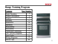
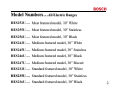
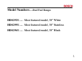
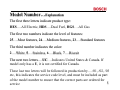
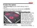
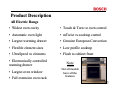
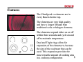
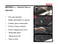
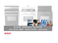
RANGE TRAINING MANUAL
ALL ELECTRIC - DUEL FUEL - ALL GAS
Range Training Program
Contents
Page Number
Model Numbers
Product Description
Features
Warranty
Installation
Operation
Disassembly
Reassembly
Thermostat Calibration
Test / Service Programs
Error Codes
Wiring Diagrams
Service Tips
2
6
8
25
26
43
57
70
73
75
85
88
105
1
Model Numbers…All Electric Ranges
HES252U…. Most featured model, 30” White
HES255U…. Most featured model, 30” Stainless
HES256U…. Most featured model, 30” Black
HES242U…. Medium featured model, 30” White
HES245U…. Medium featured model, 30” Stainless
HES246U…. Medium featured model, 30” Black
HES247U…. Medium featured model, 30” Biscuit
HES232U…. Standard featured model, 30” White
HES235U…. Standard featured model, 30” Stainless
HES236U…. Standard featured model, 30” Black
2
Model Numbers…Duel Fuel Ranges
HDS252U…. Most featured model, 30” White
HDS255U…. Most featured model, 30” Stainless
HDS256U…. Most featured model, 30” Black
3
Model Numbers…All Gas Ranges
HGS252UC….Most featured model, 30” White
HGS255UC….Most featured model, 30” Stainless
HGS256UC….Most featured model, 30” Black
HGS242UC….Medium featured model, 30” White
HGS245UC….Medium featured model, 30” Stainless
HGS246UC….Medium featured model, 30” Black
HGS247UC….Medium featured model, 30” Biscuit
HGS232UC….Standard featured model, 30” White
HGS235UC….Standard featured model, 30” Stainless
HGS236UC….Standard featured model, 30” Black
4
Model Number…Explanation
The first three letters indicate product type:
HES….All Electric, HDS….Dual Fuel, HGS….All Gas
The first two numbers indicate the level of features:
25….Most features, 24….Medium features, 23….Standard features
The third number indicates the color:
2….White, 5….Stainless, 6….Black, 7….Biscuit
The next two letters….UC….Indicates
United States & Canada. If
UC
model only has a U, it is not certified for Canada.
These last two letters will be followed in production by…./01, /02, /03
etc, this indicates the service code level, and must be included as part
of the model number to ensure that the correct parts are ordered for
5
service
Product Description
The Electric Range has three models offering a range of
features.
This product description section will describe the HES25UC
which is the range with the most features
The cooktop section
features a Touch & Turn TM
sensor pad with a central
control dial that operates all
cooktop functions. Unlike an
ordinary dial mTwisT is held
to the cooktop with a magnet
mounted behind the control
panel. When lifted off, it
Note Standard models feature
reveals a smooth, glass
mechanical controls with knobs
surface for easy cleaning
6
Product Description
All Electric Range
• Widest oven cavity
• Touch & Turn TM oven control
• Automatic oven light
• mTwist TM cooktop control
• Largest warming drawer
• Genuine European Convection
• Flexible element sizes
• Low profile cooktop
• UltraSpeed TM elements
• Flush to cabinet front
• Electronically controlled
warming drawer
• Largest oven window
• Full extension oven rack
Note
Not all models
have all the
features
7
Features
The UltraSpeed TM elements are in
every Bosch electric top.
The elements are very high quality
and have a longer lifespan than
traditional coils or halogen elements.
The elements respond either on or off
within three seconds and cycle on and
off to maintain temperature.
Dual and Triple rings allow for
expansion of the elements to increase
the size of the cookware that can be
used. This expansion provides the
most versatile amount of cooking area
8
in a cooktop configuration
mTwist TM -- Touch & Turn TM
Operation
•
Two step operation
•
Simple and intuitive to operate
•
Ceramic glass control panel
•
Touch to choose element
•
Turn to change power level
•
Removable knob
•
Safety power off
•
Easy to clean
9
Keep Warm Feature
• All elements have a “keep warm”
feature on mTwisT TM models
• Elements remain on at 3% wattage
• Excellent for holding or simmering
foods
• Indicates “keep warm” on all zones
by the letter “L” for low heat
10
Product Description -- Touch and Turn TM Control
Powerful technology made easy to use. Functions are selected
with the touch-through-glass sensor pad, then all settings are
adjusted with one central dial. It’s another Bosch innovation that
simplifies high technology with a very intuitive and easy-to-use
control
11
Control Panel Display
• Clear text display
• Intuitive operation
• Automatic help prompt
• Animated display
• Indicates preheat temperature
• Chime tones to indicate operation
• Select menu
• Displays oven & warming
operations
12
Control Panel Display -- Options
• “Lock Keys”
• Beep volume
• Sabbath mode selection
• Visible clock or no clock
• Oven calibration
• Demonstration mode
• English, French or Spanish
• Original factory settings
• F or C degree display
• 12 or 24 hour clock
13
Control Panel Display -- Features
Electronic Thermostat: The oven regulates
temperature by using a premium sensor with
state of the art software to control the elements.
Temperatures can be set from 100 F to 550 F in
5 degree increments.
Digital Display Window: The range has a full text display
window. The window displays:
• Clock
• Active elements
• Timer settings
• Temperature
• Temperature probe settings • Preheating
• Warming drawer indicator
• Remove rack reminder
• Cooking mode
• lock indicator
• Timed cooking mode
• Sabbath mode
14
Oven -- Features
Cooking Modes: The range has one of the
most versatile ovens on the market today, with
10 different cooking modes everything is
possible.
• Automatic Temperature Probe
• Thermal Bake
• Convection Bake
• Dehydrating
• Convection Roast
• Proof Mode
• Broil
• Sabbath Mode
• Keep Warm Mode
• Convection Broil
Timed Cooking Modes: Set the oven to cook in convection roast,
convection bake or thermal bake for a set period of time. The oven
shuts off once the set cooking duration has been reached. This mode
makes following a recipe easy and worry-free.
15
Oven
Delayed Start Cooking:
User can set the oven to come on at a specific time,
and cook for a specific amount of time. Meals are
then ready when the user gets home.
-- Features
Two Timers:
Timing is easy with built in timers that beep and acknowledge
time is up.
Self-Clean with Rack Removal Reminder:
Self-cleaning is an automatic 4 hour cycle, or it can be manually
set from 3to 5 hours. Once the cycle is set the oven beeps and
tells the user to remove the racks. Once the oven reaches 350 F
the oven door locks for safety. Self-clean temperature is 850 F.
Sabbath Mode:
The Sabbath mode allows the oven to remain on with or without
the light in thermal bake mode for up to 48 hours.
16
Oven Elements
Broil Element:
10-pass broil element 3,250 watts of
power. Even heat distribution, recessed for
safety, longevity and clean-ability.
Convection Element:
Gives genuine European convection TM
1,100 watts of power. Enhances multi-rack
and full meal cooking, better baking and
browning.
Bake Element:
8-pass bake element which is hidden for
safety, longevity and clean-ability. 2,000
watts of power. Takes 10 to 13 minutes to
reach 350 F in bake mode.
17
Available Cooking Modes Electric Oven
Cooking Mode
Symbol Default Temperature
Temperature Range
Elements
Convection Bake
325 degrees F
100 to 525 degrees F
Upper, lower and third
rear
Thermal Bake
350 degrees F
100 to 550 degrees F
Upper and lower
Convection Roast
325 degrees F
100 to 525 degrees F
Upper and lower
Thermal Broil
450 or 550 degrees F
Low or High
Upper
Convection Broil
550 degrees F
High (550 degrees F)
Upper and convection fan
Temperature Probe
0 degrees F
100 to 300 degrees F
Refer to all bake modes
Dehydrate
140 degrees F
100 to 160 degrees F
Proof
100 degrees F
85 to 110 degrees F
Third rear and
convection fan
Upper and lower
Sabbath
350 degrees F
100 to 550 degrees F
Upper and lower Light
on or off
Keep Warm
170 degrees F
140 to 225 degrees F
Upper and lower
Chart shows which elements are on in each of the cooking modes
18
Product Description - - Oven Cavity
• 25” extra-wide oven cavity (4.6 cu.
Ft.)
• Six rack positions
• Telescopic Rack…allows users to
check and view food without having
to pull the cookware out of the oven.
Holds up to 50lbs.
• Automatic Temperature Probe.
• Concealed Bake Element. Electronic Thermostat.
• Electronically controlled oven lighting via door
opening or touch control-2 x 40 watt incandescent
bulbs, staggered for better viewing
19
Oven Chassis
The oven can is built onto a chassis for sturdy
construction, and is built to last. This means fewer
gaps and a professional engineered fit.
20
Product Description -Warming Drawer
• Electronically controlled
temperature via sensor
• Extra wide
• 400 watt element mounted under
drawer, safe for take out containers
• High, medium and low settings
• Full extension ball bearing glides.
• Stainless steel mirror finish
• 1.3 cu.ft.
21
Duel Fuel & All Gas Range Top
Product Description
• Pro-Style continuous grates
• Low-profile to countertop
• Power-Sim Burner (Diffuser Burner)
• Sealed burners
• Electronic ignition
• Optimized burner spacing
• Precision Flame Control
22
Duel Fuel & All Gas Range Top -- Features
Burner Ratings:
RF Burner Power-Sim TM – 15,000
to a low of 1200 but with cap takes heat
output down to 400 to 500 BTUs
RR Burner 800 – 5,500
LF Burner 1,200 – 9,100
LR Burner 1,400 – 12,500
23
All Gas Range Oven -- Features
• Bake…17,000 BTUs
• Broil…14,500BTUs
• Electronically controlled
• Flame diffuser
• Even heat distribution
• Glow-bar silicon carbide igniter
• Low profile cover for more usable cooking surface
24
Warranty
• One full year Parts & Labor from date of installation or
occupancy
• Additional four years part only on the following cooktop
section parts – electrical controls, heating elements and ceramic
glass top.
• Service must be performed by an authorized service agency
• Warranty Claim must be submitted within 45 days of
completion
25
Installation…All Electric Range
Electrical Connections:
Range requires a 50 Amp 120 / 240 VAC or 120 / 208 VAC
dedicated circuit preferably with a four wire connection,
however where local codes and ordinances permit grounding
through the neutral and / or conversion to four wire is
impractical, unit may be connected to the power supply via a
three wire connection.
Connection can be made via a range cord or a flexible
conduit. If a range cord is used it must meet the above rating
requirements and be marked “For use with Ranges”
1
26
Installation…All Electric Range continued
Electrical Connections
22
27
Installation…All Electric Range
3
28
Installation…Duel Fuel Range
4
29
Installation…Duel Fuel Range
5
30
Installation…Duel Fuel Range
6
31
Installation
Anti-Tip Bracket…. Anti-Tip bracket must be installed as shown below
7
32
Installation
8
33
Conversion of Range to LP Gas -- Kit is supplied
with the range
Duel Fuel LP Kit
part # 438629
All Gas LP Kit
part # 437777
34
LP Conversion -- continued
35
LP Conversion -- continued
36
LP Conversion -- continued
37
LP Conversion -- continued
38
LP Conversion -- continued
39
LP Conversion -- continued
40
LP Conversion -- Continued
41
Door Removal
42
Operation -- Oven Control
X3
When the range is
powered up, the
interface board
receives the voltages
at X2 from the power
relay board shown in
the chart on the next
page, and the clock
illuminates.
Connector to Power
Relay Board from
“Touch & Turn”
User Interface
Board (clock)
Connector to
“Touch & Turn”
User Interface
Board (clock) from
Power Relay Board
X2
This board controls all
the functions of the
oven and contains the
program data
43
Voltage checks at the “Touch & Turn” interface
board (clock)
X2
Voltage readings at X2 NOTE
pin connections are not marked
1) 1.5 VDC
2) 0 VDC
3) 0 VDC
4) 5 VDC
5)
6)
7)
8)
0 VDC
8 VDC
0 VDC
32 VDC
Remove connector from board , set
scale to +50VDC, put one meter
lead to ground and the other lead to
pins 1, 4, 6 and 8 in turn.Voltage
should read as indicated in the
chart. If voltages are good and no
display is present, replace the
interface board.
44
X23
X3 Wiring Harness to
Interface Board
K8
X6 Latch Switches
X5 Door Switch
X7 Meat Probe
X25 Warm Drawer Sensor
K10
K7
X8 Oven Sensor
K6
K4
Power Relay
Board
Connections
Electric Oven
Lamps
K10 Convection Motor
K7 Latch Motor
X21 Neutral
X22 K6 out to Warming Ele.
X24 L1 (Red) Input to K6,
K7,K8 & K10
X17 L2 (Black) Input to K4
X16 K4 to Bake & Conv Elements
X15 K3 out to Bake Element
K3
X4
Ground
K8
N
E
U
T
R
A
L
X18 L1 (Red) Input to K5
& K3
K5
X19 K5 out to Conv. Element
K2
X13 L2 (Black) Input to K2
X12 K2 out to Broil Element
K1
X11 K1 out to Broil Element
X10 L1 (Red) Input to K1
X1 L1 (Red) Input to Board
X2 Neutral (White) to Board
45
X3 Wiring Harness to
Interface Board
X6 Latch Switches
X5 Door Switch
X7 Meat Probe
X25 Warm Drawer Sensor
X8 Oven Sensor
K8
K8
K9
K10
K10
K7
K7
K6
K6
X23
K8
Lamps
K10 Convection Motor
K7
Latch Motor
N
E
U
T
R
A
L
X21 Neutral
X22 K6 Out to Warming Ele.
X24 L1 Input to K6, K7,K8 &
K10
X4
Ground
Power Relay
Board
Connections
Gas Oven
K12
K12
K12
K11
K11
X12 From K12 to Broil Valve Coil
X11 L1 Input to K11 & K12
X10 From K11 to Bake Valve Coil
X1 L1 (Red) Input to Board
X2 Neutral (White) to Board
46
Operation of the Electric Oven
1
2
3
4
Touch Bake and set temperature at the control, relay board
receives input and checks resistance of sensor. If heat is
required then the following relays will close: K3 & K4 for the
bake element and K1 & K2 for the broil element. The output
voltages from the board should be as follows: X15-L1 to bake
element, X16-L2 to bake element. X11-L1 to broil element,
X12-L2 to broil element. This supplies 120volts from L1 & L2
giving each element 240 volts and oven heats. NOTE See
charts on next page for element “On Times”.
5
47
Element Cycle Charts
CONVECTION BAKE MODE
48
Element Cycle Charts
49
Operation of the Electric Oven
Note Some of the wiring
diagrams show a high
temperature safety
thermostat between the
terminal block and the
power relay board. This
HTC was not used on
production units.
50
Operation of the Oven Gas Burner
1
2
3
4
K11
Touch Bake and set temperature at the control,
relay board receives input and checks resistance of
sensor. If heat is required then Bake relay K11 is
closed. 120VAC is sent to the gas safety valve. The
glow igniter which is wired in series with the valve
starts to heat up, as it does so the voltage drops
across the valve. When the glow bar draws 3.2
amps and is glowing the valve opens sending gas to
the burner and it ignites. Bake is 17,000 BTUs
5
51
Electric Top Operation -- Controls
To select heating level,
touch desired element,
then twist knob.
1
2
To turn off element,
touch until “0” appears.
To keep food warm, touch element key,
then touch keep warm key.
To size pots for dual or
triple elements, press
desired element, then
press pot sizing key and
then rotate knob to
desired heating level.
If panel lock came on (if
magnetic knob was removed
for > 10 seconds), replace
knob, then push and hold
down panel lock touch key
until panel lock light goes out.
52
Electric Top Operation -- Typical Displays
Residual Heat
Element On
(showing heat level)
Dual (Outer)
Element On
(showing heat
level)
Element Off
Low (keep warm)
Panel Lock On
(when knob missing)
53
Electric Top -- How the Elements Heat
Each element or section of an element is controlled by a relay. Touch the glass to
select element, turn knob to select the power level. For the element to heat the
following relays must close:
Left Front & Right Front L2 from K10 measured at X30.
Left Front L1 from K1 900 watt measured at X5
L1 from K3 800 watt measured at X7
triple element
L1 from K4 800 watt measured at X8
Right Front L1 from K2 1200 watt measured at X6
single element
Right Rear & Left Rear L2 from K9 measured at X32.
Right Rear L1 from K5 1100 watt measured at X9
double element
L1 from K6 800 watt measured at X12
Left Rear
L1 from K7 1500 watt measured at X11
See next page for example schematic
single element
54
Electric Top -- How the Elements Heat
L1
L2 N
55
Gas Top Operation
1
2
Spark Switch
3
Sim. Light
This switch is only
for the Super-Sim
burner
Turn the control knob to the lite position. The spark switch closes and sends
120VAC to the spark module. The spark module output sends 14,000VDC to the
burner igniter creating a spark to the underside of the burner cap. The action of
turning the knob to the lite position allows gas to flow to the burner and it ignites
4
5
6
56
Gas Top Operation
Spark Switch (4)
Sim. Light
This switch is
only for the
Super-Sim
burner
Note spark switches are supplied as an assembly of four
complete with wiring harness part # 492439
56A
How to replace the “Touch & Turn” interface board
(clock)
Remove the Knob: It is a tight fit, wrap
some scotch tape around the knob & pull
gently on the ends to remove.
Remove the locknut
Remove upper rear access panel, remove connector from board, remove the 6
screws holding the board. Reassemble new board in reverse order after checking
the board configuration. See next page for instructions.
57
When a replacement board is ordered, all “Touch & Turn”
interface boards are programed for the MEDIUM featured
models for example HXS24XU: For the MOST featured
model HXS25XU snap off either one of these tabs.
For the LEAST
featured model
example
HXS23XU,
snap off both
tabs.
Note be sure to
check the model #
of the range and
configure the board
correctly before
installing.
58
Location of components Duel Fuel & All Gas
Range
Relay Board
Gas
regulator &
connection
point
Spark
Module
Convection Motor
Access to warming
drawer element
terminals
Gas safety valve
59
Disassembly….Access to maintop
1
No need to remove these
screws
3
2 Tabs
Slots
Remove knobs first if unit has mechanical controls or is a gas top. Remove the two screws
under the front panel, support the panel as you take out the second screw so that it won’t
fall. Panel is also held in place with two support tabs which fit into slots on sub-panel
5
4
Remove
these
screws
60
Disassembly….Access to maintop
6
7
Remove the 12 screws
which hold the 2 rear
panels and disconnect
the ground screw from
the maintop support
Ground
Screw
Lift the maintop a couple of inches to disengage the locking tabs and slide towards the
front of the unit. Lift the front of the maintop and fold back against the control panel.
(place towel or blanket over control panel to avoid scratching panel or maintop) The
elements, control, and latch assembly can now be accessed.
8
9
10
61
Motorized Latch Assembly & Door Switch
Remove 2 screws from front frame
Latch Motor
Latch can be accessed from under the cooktop
Latch Switches
Plunger Light Switch
62
Disassembly -- Access to maintop
Mechanical version
Each pair of
elements are held
in place by a
single bracket &
two tension clips
per element
Touch & Turn control version
Retaining Brackets
Tension Clips
63
Resistance checks can easily be made at the
element terminals Turn off power before beginning resistance checks
Right Front
Single Element
1200W
LF Triple Element
2500 Watts
2-1 70.7 Ohms
2-4 71.3 Ohms
2-3 63 Ohms
3
4
1
2
2-4 46.3 Ohms
Right Rear Double
Element 1900W
Left Rear Single
Element 1500W
2-4 37.3 Ohms
2-3 50.6 Ohms
2-4 68.5 Ohms
64
Disassembly – Touch & Turn control
1
2
3
Disconnect
wires as
needed.
Remove 2 screws holding cover Support bracket is held with 2 screws
4
Remove the support bracket
5
Lift board up and out.
6
CAUTION: Take care not
to break the plastic board
standoffs.
65
Disassembly – Touch & Turn control
7
Bottom of board showing display and magnetic switch
Underside of control showing touch pads and magnetic switch
66
Access to concealed bake element & warming
element
Rear
Warming
element
removed
from front
by
removing
the drawer
Remove this cover for access to
the warming drawer element
terminals
Front
Rear
Remove this cover for access to
the bake element
67
Access to Oven Can and Hinge Assembly
1
2
3
Remove latch assembly & top panels. Remove 3 screws on top of side panel, lift up & out to
disengage tabs at the bottom. Remove screws holding outer & inner galvanized panels.
Remove insulation (it is all in one piece) oven can is easily removed from chassis by removing
front and rear chassis frame screws. (see instructions on next page).
4
5
6
68
Access to Oven Can and Hinge Assembly -continued
Remove these
screws
69
Reassembly -- Control board (1)
The control board must be reassembled so 4 of the 6 light blue standoffs
(“pins”) engage the 4 holes in the metal plate glued to the Ceran glass
maintop. If not, the magnetic knob & digital displays won’t line up.
NOTE: The other 2 standoffs don’t engage any holes in the plate.
CAUTION: Don’t force the standoffs in place (so they’re not broken).
70
Reassembly -- Control Board (2)
Before mounting the control board, make sure each of the 6 light blue
standoffs (“pins”) are inserted properly into the component boards.
The two boards should be parallel.
In addition, make sure there is no debris between the touch pads and
the glass, and that the pads are making good contact with the glass. If
not it will not work and may show an error code.
71
Reassembly of cooktop control knob, spring &
bezel
1
3
Assemble
knob spring
& bezel.
Hold
assembly
together and
install on
shaft
2
4
72
How to calibrate the Thermostat ( change the offset )
Touch cooking mode
& keep your finger on
there until “SELECT
FUNCTION” appears
(about 5 secs.)
1
3
Using control knob,
scroll through menu
until “OVEN TEMP
OFFSET” appears.
Touch start and a
number will appear in
the temperature
window. If the oven
has never been
calibrated before it
will be 0 degrees F
2
4
73
5
6
Using the control knob scroll through
the temperature options. The
temperature ranges from –25 degrees F
to + 25 degrees F . Select the number
of degrees that the temperature needs
to be changed by and touch “START”.
Display will show “SELECT
FUNCTION”, touch “OFF” to
complete the change.
7
74
Range Test / Service Program
The range control has a service program that can be accessed by the service
technician to check component and /or function.
To enter the service program, do the following:
Place a finger on the cooking mode, temperature and start zones simultaneously
for 5 seconds… the word “TEST” will display. Touch cooking mode and
“SERVICE” will display.
1
2
75
Touch start and “LIGHT” will display, at this point the light function can be
tested by touching start again, or use the rotary control knob to scroll through the
different test functions. To check a particular function rotate to that function then
touch start. To exit the program at any time touch cancel.
Note: During all functions the maximum oven temperature is 200 degrees F, if
reached the display shows “TOO HOT” and any function in operation stops,
except the Cancel ( which allows exit from the program).The test can be resumed
once the temperature falls below 200 degrees F.
3
4
76
Electric Oven
Function 1:
1. Display “LIGHT”
2. Press Start Zone to activate oven light relay.
3. Display “ LIGHT ON”
4. Press Start Zone to de-active oven light relay.
5. Display “LIGHT”
6. Allow user to continue toggling.
7. Rotating the selection knob will de-activate the light relay (if on) and scroll display to
function select (Light, Conv Fan, Ring, etc.).
Function 2:
1. Display “CONV FAN”
2. Press Start Zone to activate Convection fan relay.
3. Display “ FAN ON”
4. Press Start Zone to de-active Convection fan relay.
5. Display “FAN”
6. Allow user to continue toggling.
7. Rotating the selection knob will de-activate the Fan relay (if on) and scroll display to
function select (Light, Conv Fan, Ring, etc.).
77
( g
g
)
Function 3:
1. Display “RING” (if applicable for version)
2. Press Start Zone to activate Conv. fan relay and Ring element relay.
3. Display “ RING ON”
4. Press Start Zone to de-active Conv. Fan relay and Ring element relay.
5. Display “RING”
6. Allow user to continue toggling.
7. Rotating the selection knob will de-activate the Ring and Fan relay (if on) and scroll
display to function select (Light, Conv Fan, Ring, etc.).
Function 4:
1. Display “BROIL”
2. Press Start Zone to activate Broil element relay.
3. Display “ BROIL ON”
4. Press Start Zone to de-active Broil element relay.
5. Display “BROIL”
6. Allow user to continue toggling.
7. Rotating the selection knob will de-activate the fan relay (if on) and scroll display to
function select (Light, Conv Fan, Ring, etc.).
78
Function 5:
1. Display “BAKE”
2. Press Start Zone to activate Bake element relay.
3. Display “ BAKE ON”
4. Press Start Zone to de-active Baker element relay.
5. Display “BAKE”
6. Allow user to continue toggling.
7. Rotating the selection knob will de-activate the Bake relay (if on) and scroll display to
function select (Light, Conv Fan, Ring, etc.).
Function 6:
1. Display “WARMING DRAWER” (if applicable for Version)
2. Press Start Zone to activate Warming Drawer element relay.
3. Display “ WARMING D ON”
4. Press Start Zone to de-active Warming Drawer element relay.
5. Display “WARMING DRAWER”
6. Allow user to continue toggling.
7. Rotating the selection knob will de-activate the Warming Drawer relay (if on) and scroll
display to function select (Light, Conv Fan, Ring, etc.).
79
Function 7:
1. Display “SENSOR CHECK”
2. Press Start Zone to active control to automatically perform self check of:
3. Self check for Meat probe resistance (if applicable for version)
4. Self check for oven sensor resistance
5. Self check for warming drawer sensor resistance (if applicable for version)
If self-check finds a failure during this sensor check, the alpha display shows which one
with “FAILURE PROBE” or “FAILURE OVEN” or “FAILURE W D”
6. If no failure is found, the Display shows “SENSORS OK”
7. Rotating the selection knob will de-activate the Sensor check mode and scroll display to
function select (Light, Conv Fan, Ring, etc.)
Function 8:
1. Display “CHECK LATCH”
2. Press Start zone. Control activates door latch. Control operates as if in normal self-clean
mode, checking for switch logic and time out functions. Lock icon should operate as in
normal operation. Once latch is locked, motor stops and icon is steady state. All errors
should show if malfunction or non-locking is detected. Further pressing of the Start Zone
will be ignored until the latch has locked or an error has been detected.
3. Press Start zone. Control de-activated door latch. Control operates as if in normal selfclean mode, with all checks, icon change (lock flashing then off) and error detection.
Further pressing of the Start Zone will be ignored until the latch has un-locked or an error
has been detected.
4. If an error is detected, the latch motor will stop and the display will show that code and
beep.
5. Allow user to continue toggling.
6. Rotating the selection knob will de-activate the Check Latch mode and reset to home (if
locked) and scroll display to function select (Light, Conv Fan, Ring, etc.).
80
Gas Oven
Function 1:
1. Display “LIGHT”
1. Press Start Zone to activate oven light relay.
2. Display “ LIGHT ON”
3. Press Start Zone to de-active oven light relay.
4. Display “LIGHT”
5. Allow user to continue toggling.
6. Rotating the selection knob will de-activate the light relay (if on) and scroll display to
function select (Light, Conv Fan, Warming Drawer, etc.).
Function 2:
1. Display “CONV FAN”
2. Press Start Zone to activate Convection fan relay.
3. Display “ FAN ON”
4. Press Start Zone to de-active Convection fan relay.
5. Display “FAN”
6. Allow user to continue toggling.
7. Rotating the selection knob will de-activate the Fan relay (if on) and scroll display to
function select (Light, Conv Fan, Warming Drawer, etc.).
81
Function 3:
1. Display “WARMING DRAWER” (if applicable for Version)
2. Press Start Zone to activate Warming Drawer element relay.
3. Display “ WARMING D ON”
4. Press Start Zone to de-active Warming Drawer element relay.
5. Display “WARMING DRAWER”
6. Allow user to continue toggling.
7. Rotating the selection knob will de-activate the Warming Drawer relay (if on) and scroll
display to function select (Light, Conv Fan, Warming Drawer, etc.).
Function 4:
1. Display “SENSOR CHECK”
2. Press Start Zone to active control to automatically perform self check of:
3. Self check for Meat probe resistance (if applicable for version)
4. Self check for oven sensor resistance
5. Self check for warming drawer sensor resistance (if applicable for version)
If self-check finds a failure during this sensor check, the alpha display shows which one
with “FAILURE PROBE” or “FAILURE OVEN” or “FAILURE W D”
6. If no failure is found, the Display shows “SENSORS OK”
7. Rotating the selection knob will de-activate the Sensor check mode and scroll display to
function select (Light, Conv Fan, Warming Drawer, etc.).
82
Function 5:
1. Display “BROIL”
2. Pressing Start Zone activates Broil relay for 120 seconds
3. Display “BROIL ON”
4. Pressing Start Zone De-activates Broil relay
5. Display “BROIL”
6. Allow user to continue toggling.
7. While Broil is on, Controller times for 120 seconds. If user does not turn off broil relay
within the 120seconds, controller turns off automatically (also max temp of 200F is
monitored).
8. Rotating the selection knob will de-activate the Check Latch mode and reset to home (if
locked) and scroll display to function select (Light, Conv Fan, Warming Drawer, etc.).
Function 6:
1. Display “BAKE”
2. 2. Pressing Start Zone activates Bake relay for 120 seconds
3. Display “BAKE ON”
4. Pressing Start Zone De-activates Bake relay
5. Display “BAKE”
6. Allow user to continue toggling.
7. While Bake relay is on, Controller times for 120 seconds. If user does not turn off broil
relay within the 120seconds, controller turns off automatically (also max temp of 200F is
monitored).
8. Rotating the selection knob will de-activate the Check Latch mode and reset to home (if
locked) and scroll display to function select (Light, Conv Fan, Warming Drawer, etc.).
83
Function 7:
1. Display “CHECK LATCH”
2. Press Start zone. Control activates door latch. Control operates as if in normal self-clean
mode, checking for switch logic and time out functions. Lock icon should operate as in
normal operation. Once latch is locked, motor stops and icon is steady state. All errors
should show if malfunction or non-locking is detected. Further pressing of the Start Zone
will be ignored until the latch has locked or an error has been detected.
3. Press Start zone. Control de-activated door latch. Control operates as if in normal selfclean mode, with all checks, icon change (lock flashing then off) and error detection.
Further pressing of the Start Zone will be ignored until the latch has un-locked or an error
has been detected.
4. If an error is detected, the latch motor will stop and the display will show that code and
beep.
5. Allow user to continue toggling.
6. Rotating the selection knob will de-activate the Check Latch mode and reset to home (if
locked) and scroll display to function select (Light, Conv Fan, Warming Drawer, etc.).
84
Range Error Codes
CODE
DESCRIPTION
Cook or clean programmed
When W. Drawer is active
Latch should be locked
Latch should be unlocked
Always
Latch unlocked
Latch locked
Always
FAULT
LIMIT
20 sec
20 sec
1 min
1 min
1 min
5 sec
5 sec
1 min
Always
1 min
Slave micro not functioning
Eeprom failure or communication circuit failure
User Interface too hot
Power Board too hot
Cook profile corrupted in EPROM
Always
Cook or clean programmed
Always
Always
Cook or clean programmed
1 min
1 sec
1 sec
1 sec
1 sec
F170
F190
F200
Power Failure
Power over voltage
Time out and stop function
2 ms
F210
Range exceeded safe test limits
Always
At power on
During Production test
mode
During Service test mode
F31
F33
F41
F43
F45
F111
F113
F121
Oven temperature sensor failure
Warming Drawer Sensor Failure
Motorized latch will not lock
Motorized latch will not unlock
Motorized Latch both locked and unlocked
Runaway Oven temperature 585°F
Runaway Oven temperature 950°F
Stuck key in the membrane switch layer
F125
Cancel key circuit problem
F141
F151
F153
F154
F155
WHEN CHECKED
110 sec.
200°F
85
Range Error Codes -- Additional Information
CODE
F1
F2
F3
DESCRIPTION
Meat probe not there or incorrect
WHEN CHECKED
During test / use
Oven sensor not correct
During test / use
Warming sensor not correct
During test / use
DOOR Door latch problem
LATCH
ERROR
During self-clean
ERROR Temp. reaches 585 degrees F . Display shows “ During any
CONTACT SERVICE” and beeps. The beep
cooking mode
can be stopped with touching cancel zone, but
display will stay up with program locked until
main power is removed for a minimum of 5
seconds. If the temperature continues to rise
(due to stuck relay) the latch will lock at 600
degrees F
Note: Depending on model, program will only look for probes or sensors that it should have.
86
Wiring Diagrams & Schematics
There is a wiring diagram & schematic on the rear cover of
each range
87
HES25U Wiring Diagram
88
L1 Red
L2 N
HES25U
Cooktop
Schematic
89
HES25U
Oven
Schematic
90
HES 24U Wiring Diagram
91
L1
L2 N
HES24U
Cooktop
Section
Schematic
92
HES24U
Oven
Section
Schematic
93
HES23U Wiring Diagram
94
HES23UC
Schematic
95
HDS25UC Wiring Diagram
96
HDS25U
Schematic
97
HGS25UC Wiring Diagram
98
L1
N
HGS25UC
Cooktop
Section
99
HGS25UC
Oven
Section
100
HGS24UC Wiring Diagram
101
HGS24UC Schematic
102
HGS23UC Wiring Diagram
103
HGS23UC
Schematic
104
Electric Maintop Service Tips -Troubleshooting
Symptom
Problem
Solution
Panel lock Magnetic knob has been Replace magnetic knob, then press and hold
light is on.
removed or panel lock key panel lock key until light goes out.
has been pressed.
Cooktop
Power is off or control Check incoming power. If OK (240 VAC),
won’t run at board has failed.
then replace control board.
all.
Element
Element has failed.
Disconnect power and measure resistance at
won’t heat.
control board or element terminals (see
resistance charts). Replace faulty element.
Element
Wire harness is damaged Check wire harness for continuity and to
won’t heat. or shorted.
ground (to check for shorts). Replace faulty
wire harness.
WARNING! Disconnect cooktop before starting any repairs.
105