1
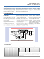
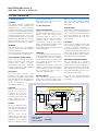
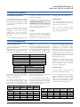
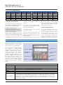
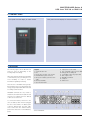
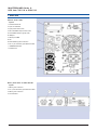
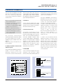
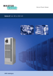
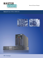
Secure Power Always
Series A from 700 to 3000 VA
UPS Catalogue
Important note!
The technical data enclosed is for general information. Please
note that the operating instructions and references indicated on
the products are for installation, operation and maintenance.
Product designations
All product designations used are trademarks or product names
of Chloride Group PLC or its subsidiary companies.
This publication is issued to provide outline information and is
not deemed to form any part of any offer or contract. The
company has a policy of continuous product development and
improvement and we therefore reserve the right to vary any
information quoted without prior notice.
Person to contact
Uninterruptible
Power Supply
UPS Catalogue • 2009
Series A
from 700 VA to 3000 VA
1. SCOPE
2
2. SYSTEM DESCRIPTION
2
3. DEVICE DESCRIPTION
3
4. GENERAL REQUIREMENTS
4
5. BATTERY MANAGEMENT
4
6. CONTROL PANEL
5
7. REAR SIDE
6
8. INTERFACES & CONNECTIVITY
8
9. MECHANICAL DATA
9
10. TECHNICAL DATA
11. OPTIONS
01
9
10
MKA4CAT0UKAG4MG/Rev. 1-01/2009
MASTERGUARD Series A
UPS from 700 VA to 3000 VA
1. SCOPE
This document describes a continuous
duty single-phase output, on-line double
conversion uninterruptible power supply
( U P S ) s ys t e m . Th e U P S s h a l l
automatically provide continuity of
electrical power, within defined limits
and without interruption, upon failure or
degradation of the commercial AC
source. The continuity of conditioned
electric power shall be delivered for the
time period defined by the battery
system, which will be automatically
recharged by the UPS upon restoration
of the commercial AC source.
as shown in the figure below, and shall
provide the following benefits:
• High energy efficiency in power
conversion, including ECO mode
• Outstanding output power factor=
0,9 (*)
• Easy-swappable internal batteries, for
simplified maintenance without
disconnecting the loads
• Advanced
battery
management,
increasing battery life
• Simplified commissioning, thanks to
the auto-detection of external battery
packs
• User-friendly
notification
and
interaction with the standard front
panel with LED indicators and the
optional LCD Display
• Intelligent load management provided
by the controllable output sockets
• Possibility of operation as frequency
converter
• Availability of internal automatic
bypass to keep the load fed in the
event of a UPS failure, reducing
disruption and maximising uptime
• Minimization of mains distortions
thanks to the enhanced input power
factor correction.
2. SYSTEM DESCRIPTION
2.1 The system
An increasing number of devices are
sensitive to disturbances on the mains
power supply. The Series A UPS system
shall provide high quality AC power for
connected equipment and offer the
following features:
• Protection against power failures
• Improvement in the power supply
quality
• Compatibility with all types of load
Series A shall operate based on DSPdriven Double Conversion technology,
PFC
Inverter
+V
Filter
Filter
L
L
-V
N
N
Charger
Booster
+
-
E
E
Series A block diagram
2.2 Models available
The Series A product range shall include the following single-phase pluggable models and external battery packs:
UPS Model
A700-T
A1000-T
A1500-T
A1000-RT
A1500-RT
A2000-RT
A3000-RT
Housing
Tower
Tower
Tower
Rack/Tower
Rack/Tower
Rack/Tower
Rack/Tower
MKA4CAT0UKAG4MG/Rev. 1-01/2009
Rating (*)
700VA/630W
1000VA/900W
1500VA/1350W
1000VA/900W
1500VA/1350W
2000VA/1800W
3000VA/2700W
Housing
Battery Pack
Tower
BP-A1000/1500-T
Rack/Tower
BP-A1000/1500-RT
BP-A2000/3000-RT Rack/Tower
Compatible UPS
A1000-T / A1500-T
A1000-RT / A1500-RT
A2000-RT / A3000-RT
(*) These ratings are only valid for the UPS without external battery packs
and considering a nominal voltage of 230 V. Check technical data for
further details.
02
MASTERGUARD Series A
UPS from 700 VA to 3000 VA
3. DEVICE DESCRIPTION
3.1 Components/blocks
CHARGER
The charger includes a temperature
compensation which regulates the
charging process. When the mains
voltage is within tolerances, the charger
provides a nominal recharge current up
to 1.2A to the batteries. This element is
current-limited; therefore, it can only
provide the nominal current, although
batteries may demand more current.
Typical recharge time for internal
batteries is 4 hours (for 90% recharge).
INVERTER
The inverter consists of a half-bridge
topology which uses high frequency
switching technique.
The inverter is protected against output
short-circuits and is current-limited.
LOGIC CONTROL BASED ON DSP
Logic control provided by a powerful
Digital Signal Processor (DSP) shall
sample the output voltage,
immediately detecting
abnormal
voltage conditions and then operating
the appropriate commands.
PFC CIRCUIT
The power factor correction circuit
provides a very high input current
power factor (~0,99), thus reducing the
input disturbances and optimizing the
energy usage. It also contributes to
avoid the introduction of
disturbances upstream.
BOOSTER
Thanks to this element, the
b a t t e r i e s’ v o l t a g e i s
increased up to DC bus
voltage for the inverter to
provide the pure sinusoidal
output when the unit is
working on battery mode.
FILTERS
On the one hand, the input
filter reduces disturbances
coming from mains and sets
up the signal for the PFC
circuit.
On the other hand,
inductances at the inverter
output, together with output
capacitors, act as a filtering
element to obtain the output
pure sinusoidal waveform.
Both filters work even if the unit is
working in bypass mode.
Batteries supply the energy and the
user can see the estimated battery
runtime by using the software or the
LCD display.
3.2 Operating modes
START-UP SEQUENCE
When the unit is connected to the
mains, it automatically starts to work in
bypass mode and thus powers
connected loads. To switch to line
mode, the user must press the inverter
O n / O ff b u tt o n . A ft e r i nve r t e r
disconnection through the On/Off
button, the unit returns to bypass mode
whenever the mains is present.
This sequence allows the load to be fed
whenever possible.
LINE MODE
In use, the input AC is converted to DC,
and converted back to a pure sinewave.
It prevents the load from suffering
power line problems (including total
loss of input AC power) and corrects
the load power factor.
The inverter is constantly synchronised
with the input line, thus allowing load
transfer from the inverter to the bypass
line to power the load in case of
overloads or inverter stops.
BATTERY MODE
UPS switches automatically to this
mode when detecting a mains failure
(and the unit is not in bypass mode).
PFC
+V
Filter
BYPASS MODE
In this case, the load is directly fed from
the AC mains. It can be forced by the
user or activated automatically by the
UPS when detecting an overload or
other internal failure. This is also the
start-up mode.
ECO MODE
If this mode is enabled, the unit will
work in automatic by-pass when mains
is within tolerances. Otherwise, it
automatically switches to line mode (if
possible, as the voltage input window is
wider in line mode) or to battery mode.
A very high efficiency (up to 97%) is
achieved in this mode of operation.
FREQUENCY CONVERTER MODE
The unit operates as a frequency
converter, providing 50 or 60 Hz at
output when the input frequency is
within 40-70 Hz. There is a power derating (50%) when using this mode.
ECO mode and by-pass mode are not
accessible from this mode.
The user can activate/deactivate
several of these operating modes via
LCD Display.
Inverter
Filter
L
L
-V
N
N
Charger
Booster
+
-
E
E
Bypass Mode
Line Mode
Battery Mode
03
MKA4CAT0UKAG4MG/Rev. 1-01/2009
MASTERGUARD Series A
UPS from 700 VA to 3000 VA
4. GENERAL REQUIREMENTS
4.1 Standards and certifications
accordance with the following
international standards:
MASTERGUARD GmbH is certified by the
German TÜV as a company with a quality
and environmental management system
in accordance with standards ISO 9001
and ISO 14001.
Series A shall carry the CE mark in
accordance with the Safety Directive
2006/95/EC and the EMC Directive
2 0 0 4 / 10 8 / E C ( s u p e r s e d i n g t h e
89/336/EEC, 92/31/EC and 93/68/EEC
Directives).
Series A is designed and manufactured in
Electrical and Electronic Equipment.
4.3 Neutral/earth
• EN62040-1-1, EN 60950 (RD); general
and safety requirements
• EN62040-2 Class C2, EMC requirements
Series A shall also bear the TÜV and
UL/cUL certifications for safety.
4.2 RoHS
Series A neutral output is not connected
to the earth and battery negative voltage
is referenced to neutral output.
Series A shall not modify the neutral
state, with the exception in battery mode
due to the backfeed protection.
Series A voluntarily complies with the
requirements of the Directive 2002/95/EC
regarding Restriction of the Use of Certain
Hazardous Substances (RoHS) in
5. BATTERY MANAGEMENT
5.1 Battery configurations
Series A shall include the configurations
shown in the tables below:
Batteries shall be sealed, lead-acid and
maintenance-free. Internal batteries in the
UPS are easy-swappable. UPS includes
Configuration
1x2x7.2Ah (24Vdc 7.2Ah)
1x3x7.2Ah (36Vdc 7.2Ah)
1x3x45W (36Vdc 45W)
1x6x7.2Ah (72Vdc 7.2Ah)
1x6x45W (72Vdc 45W)
UPS Model
A700-T
A1000-T/A1000-RT
A1500-T/A1500-RT
A2000-RT
A3000-RT
Battery Pack
BP-A1000/1500-T
BP-A1000/1500-RT
BP-A2000/3000-RT
Test of battery system shall be run upon
user request (via front panel) or at regular
intervals (daily, weekly or monthly). These
intervals can be configured via LCD
1000 VA
models
UPS
UPS + 1BP
UPS + 2BP
UPS + 3BP
UPS + 4BP
110 W
35 min
160 W
37 min
158 min
254 min
397 min
476 min
280 W
15 min
400 W
15 min
55 min
97 min
174 min
220 min
MKA4CAT0UKAG4MG/Rev. 1-01/2009
5.2 Back-up times
The above battery configurations shall
provide the following back-up times.
can be configured by the user (via LCD
display) to 25%, 50% or 75%.
An end-of-battery-life alarm shall be
activated 4 years after commissioning to
alert the operator that batteries should be
replaced. This alarm can be deactivated by
the operator via front panel.
390 W
10 min
560 W
11 min
38 min
69 min
99 min
161 min
560 W
5 min
1500 VA
models
UPS
UPS + 1BP
UPS + 2BP
UPS + 3BP
UPS + 4BP
800 W
6 min
25 min
46 min
67 min
89 min
04
The UPS shall automatically detect the
number of external battery packs
connected via communication cables
(bundled with the batter y packs)
interconnected between the UPS and the
battery packs. Internal calculations about
back-up time are done according to the
quantity of battery packs connected. It is
recommended a maximum of 4 external
battery packs to each UPS.
Additional battery arrangements may be
configured, as well as external battery
chargers. Please check the details with
the local Chloride office for these
customized configurations.
Configuration
2x3x7.2Ah (36Vdc 14.4Ah)
2x3x7Ah (36Vdc 14Ah)
2x6x45W (72Vdc 90W)
internal protection against overvoltages
and deep discharge protection to
maximize reliable battery life.
700 VA
model
UPS
display.
A pre-alarm signal shall be activated
before the end of battery back-up to alert
the operator (BATTERY LOW signal). By
default, this signal shall be activated when
the remaining battery capacity goes
below 25% of the total capacity. This value
240 W
25 min
84 min
180 min
234 min
331 min
They are typical back-up times assuming
resistive load, batteries fully charged and
ambient temperature of 25ºC. These
values may vary depending on these
conditions. 700 VA model does not allow
connection of external battery packs.
600 W
10 min
34 min
62 min
90 min
140 min
840 W
7 min
24 min
43 min
63 min
83 min
1200 W
3 min
16 min
28 min
42 min
56 min
MASTERGUARD Series A
UPS from 700 VA to 3000 VA
5. BATTERY MANAGEMENT
2000 VA
models
UPS
UPS + 1BP
UPS + 2BP
UPS + 3BP
UPS + 4BP
800 W
15 min
58 min
108 min
177 min
213 min
320 W
37 min
163 min
236 min
358 min
445 min
1120 W
11 min
40 min
73 min
114 min
166 min
5.3 Charger / Recharge process
The charger shall operate when the AC
mains supply is available and shall have
the following operating parameters:
3000 VA
models
UPS
UPS + 1BP
UPS + 2BP
UPS + 3BP
UPS + 4BP
1600 W
6 min
27 min
49 min
71 min
96 min
480 W
26 min
90 min
182 min
226 min
282 min
charged and optimum operational
condition.
For discharge, cut-off voltage will vary
from 1.6V to 1.88V, depending on output
load and discharge profile.
• Charger voltage: 2.3V /cell
• Charger DC current limitation: 1.2A
• Typical recharge time (for internal UPS
batteries): 4 hours @ 90%
The battery recharge process shall
comprise two stages:
Charger will be operating just after AC
mains connection (line, ECO, bypass and
f r e q u e n c y c o nve r t e r m o d e s ) t o
automatically keep the batteries in a fully
A) In the first stage (constant current), the
charger injects 1.2A (maximum) to the
batteries until the battery voltage reaches
the floating value.
B) Once the floating voltage is reached,
1200 W
11 min
37 min
66 min
98 min
150 min
1680 W
7 min
26 min
47 min
68 min
92 min
2400 W
3 min
18 min
31 min
46 min
60 min
the second stage (constant voltage)
starts. During this stage, the charger
keeps this floating voltage while the
charger current decreases.
5.4 Easy-swappable batteries
The UPS internal batteries shall be easyswappable, allowing the ser vice
engineers to replace the batteries without
disconnecting the load.
It is
recommended to switch to bypass mode
in this mode. Thanks to this feature,
batteries can be replaced without any
disturbance or disconnection to the load.
6. CONTROL PANEL
The UPS incorporates the controls and
indicators necessar y to monitor the system
status and performance, so users will be
able to take actions where appropriate.
Series A includes a multiple language
L C D di splay f o r comp le t e U PS
monitoring and control. The text is
available in English, French, German,
I ta lian, Po r tu gu ese an d S p anish.
Complete access to LCD menu is
p oss ible thr ough navi gation p ush
buttons located below the screen. The
LCD panel may be rotated to fit
horizontal and vertical mounting. It
contains all actions available through
LED panel and includes additional
options. A brief summary is shown
below:
PANEL WITH LCD
Menus
Control Menu
Status Menu
Setup Menu
Logging
About
Advanced Options
Fault LED
Inverter LED
Bypass Mode/Eco
mode LED
inverter ON/PFF
Button
Mains LED
Enter Button
ESC Button
Scroll Down
Button
Actions
Enable/disable acoustic alarm and run battery tests.
It shows UPS status, including input/output parameters
It allows the user to select the language and the output voltage
It contains a historic log with the most relevant events
Information about UPS model and rating
For settings that may require advanced configuration of the UPS and operation. It is password
protected. Most actions are taken through this menu: output frequency selection, turn UPS
to bypass (Eco or Line Mode), settings and levels for controllable outlets, cold start, low
battery alarm selection, auto-restart function and other actions specified in the user manual
(please check for details).
05
MKA4CAT0UKAG4MG/Rev. 1-01/2009
MASTERGUARD Series A
UPS from 700 VA to 3000 VA
6. CONTROL PANEL
Front panel with LCD display for tower models
Front panel with LCD display for rack/tower models
7. REAR SIDE
The following figures show different rear
sides for Series A depending on the
housing and power ratings.
All models include RS232 and USB (HID)
communication ports, providing the user
more flexibility in order to obtain
information regarding monitoring.
Legend:
1. Communication slot
2. Fan
3. Fan (In other models, only one fan)
4. External battery pack connector
5. RJ11 port for battery pack detection
cable
6. RS232 port (DB9)
7. Input circuit breaker
There are two controllable outlets groups.
By using them, the user can maximize the
energy usage and prioritize different loads
according to their relevance.
RPO/ROO terminals are very useful to
shutdown / shutdown and restart the unit
remotely, for example when it is difficult
to have access to the UPS.
To connect the battery extension to the
UPS, the battery cable must be plugged
into the socket and into one battery pack
connector. Besides this, the RJ11 cable
must connect the UPS and the battery
pack for auto detection of external battery
packs.
MKA4CAT0UKAG4MG/Rev. 1-01/2009
Series A 3000 RT
06
8. Input power socket (16A)
9. Not controllable output sockets (10A)
10. Fixing point for sliding rail
11. Controllable outlets (2 groups,10A)
12. 16A output socket
13. ROO/RPO terminals
14. USB port
15. Earth screw
MASTERGUARD Series A
UPS from 700 VA to 3000 VA
7. REAR SIDE
Series A Tower 1500
Legend:
1. Communication slot
2. Input circuit breaker
3. Input power socket (10A)
4. Not controllable output sockets (10A)
5. Controllable outlets (2 groups,10A)
6. USB port
7. RS232 port (DB9)
8. Fan
9. External battery pack connection
10. RJ11 port for battery pack detection cable
11. ROO/RPO terminals
12. Earth Screw
Battery Pack Series A 1000/1500 RT
Legend:
1. Battery pack connector
2. RJ11 ports for battery pack detection cable
3. Battery pack connector
1
4. Circuit breaker
07
2
3
4
MKA4CAT0UKAG4MG/Rev. 1-01/2009
MASTERGUARD Series A
UPS from 700 VA to 3000 VA
8. INTERFACES & CONNECTIVITY
Series A shall be equipped with DB9
and USB communication ports and a
slot for inserting advanced
communication cards. These interfaces
can be used for:
RS232 signals (RxD and TxD) and 5
output signals. They shall be available as
opto-coupled, open collector signals.
Pin distribution shall be as indicated in
figure “DB9 pin distribution”.
• Direct communication between UPS
and workstation/server
• Integration of the UPS as client into
a network with centralized
monitoring via a ManageUPS SNMP
adapter in the interface slot
• Transfer of operational states to
external alarm systems via volt-free
contacts (with interface volt-free
contact card, available as accessory,
in the interface slot).
8.2 USB port
Th e n e c e s s a r y c o m m u n i c a t i o n
software packages and interface cables
are either bundled with the UPS or
available as options. Please refer to the
website
http://connectivity.chloridepower.com
for more details.
8.1 DB9 port (RS232 communication
and basic signals)
Series A shall be equipped with a USB
communication port for protocol-data
transfer. This port shall be classified as
HID (Human Interface Device).
8.3 Communication slot
The Series A communication slot may
be fitted with various interface cards.
Interface cards available as accessories
shall come with detailed descriptions
enclosed. Available interface cards
include SNMP adapters (ManageUPS
NET) for connecting the UPS to a TCP/IP
network or the volt-free contacts
adapter. Please see section 11 for more
details. Users are advised to follow
carefully the installation guidelines
attached to the accessories.
8.4 RPO/ROO
Series A shall be equipped with a 9-pole
SUB-D connector (DB9 port),
electrically isolated from all other
circuits. This connector shall contain the
On Off) devices. The terminals shall be
located on the rear side of the unit (see
section 7 for more details).
The figure “ROO/RPO” shows the pin
distribution. The unit comes out of the
factory with a wire which connects pins
1 and 2. For normal UPS operation,
these pins must be kept connected.
In order to use the Remote Power Off
(RPO) functionality, a normally closed
volt-free contact has to be inserted
between pins 1 and 2. When this
contact is open, the UPS will
disconnect all loads and shut down. To
return to normal operation, it is
necessary to close the contact and
restart the unit.
In order to use the Remote On Off
(ROO) functionality, a normally closed
volt-free contact has to be inserted
between pins 2 and 3, while keeping
the pins 1 and 2 interconnected. When
the contact between 2 and 3 is open,
the UPS will disconnect all loads. After
that, if the contact is closed the unit will
restart and restore power to the
connected loads.
Series A shall be equipped with three
terminals for the connection of RPO
(Remote Power Off) and ROO (Remote
TXD
2
RXD
3
3
2
1
4
BYPASS ACTIVE
7
SUM ALARM
8
BATT LOW
1
AC FAIL
6
AC FAIL
9
SGN
5
ROO
3
2
1
DB9 pin distribution
RPO
MKA4CAT0UKAG4MG/Rev. 1-01/2009
08
MASTERGUARD Series A
UPS from 700 VA to 3000 VA
9. MECHANICAL DATA
9.1 Enclosure
9.2 Ventilation
9.3 Installation of rack/tower units
The UPS shall be housed in an
enclosure with removable front panels
(UPS internal batteries shall be
accessible from the front panel) and
IP20 protection. Standard colour of the
enclosure shall be RAL7016 (grey
anthracite), thus providing an optimum
alternative for most environments.
Forced air cooling shall ensure that all
the components are operated within
their specification. Airflow shall be
controlled according to load demand.
The cooling air entry shall be on the
front panel and the air exit on the rear
side.
The rack/tower units can be rackmounted into 19” cabinets or installed
as tower (floorstanding). The required
mounting elements for both situations
are either bundled with the units or
available as options.
10. TECHNICAL DATA
UPS Rating
Housing
Technology
Output Power(1) (VA/W)
INPUT
Nominal input voltage (VAC)
Operative input voltage range @ nominal power(VAC)
Maximum operative input voltage range
Operative input voltage range in ECO/bypass mode (VAC)
Nominal input frequency (Hz)
Operative input frequency range (Hz)
OUTPUT
Nominal output voltage(2) (VAC)
Voltage regulation (%)
Output frequency (Hz)
BATTERIES
Type
Battery management
(3)
Typical autonomy
GENERAL
Efficiency in line mode(4) (%)
Typical acoustic noise in on-line mode (dBA)
Inrush current
CONNECTIVITY
Communication Ports(5)
Communication Slot
Remote Power Off (RPO)
Remote On/Off (ROO)
ENVIRONMENTAL
Operating temperature
Storage temperature
Altitude & Relative humidity
MECHANICAL
Size (WxHxD, mm)
Weight (kg)
A 700-T
700 VA
Tower
700/630
A2000-RT
A1000- T
A 1000 -RT
A 1500 -T
A1500-RT
A3000-RT
1000 VA
1500 VA
2000 VA
3000 VA
Tower
Rack/Tower
Tower
Rack/Tower Rack/Tower Rack/Tower
Advanced on-line double conversion
2000/1800 3000/2700
1000/900
1500/1350
200 - 240 V
From nominal voltage -10% to 284 V
120 - 284 V
191 - 264 V
50/60Hz auto-selection
50/60Hz +/-5% (40-70Hz in Frequency Converter Mode)
140 - 284 V
200 / 208 / 220 / 230(default) / 240 V
3%
50/60Hz ±0,5% (same as input or selectable in Frequency Converter Mode)
8 min
86%
39
Sealed maintenance-free lead acid (VRLA)
Advanced battery care and external battery pack autodetection
9 min
6 min
9 min
86%
39
40
86%
39
6*Imaxpk<1 ms
88%
46
40
6 min
90%
46
RS232/USB / status signals
1 slot for SNMP or volt-free contacts card
Yes
Yes
0 - 40 ºC
-15ºC / +40ºC
0-3000m / 20% to 90% (non condensation)
157x245x438 157x245x438 438x86.5(2U)x482 157x245x488 438x86.5(2U)x482 438x86.5(2U)x657 438x86.5(2U)x657
12.3
15
17.9
17.6
20
26
31
(1) Output power with external battery packs is: 1000 VA models: 1000 VA/800 W, 1500 VA models: 1500 VA/1200 W, 2000 VA
models: 2000 VA/1600 W, 3000 VA models: 3000 VA/2400 W. For 200, 208 and 220 Volts the output power factor is 0.8.
(2) For output nominal voltages 200 V and 208 V, there is a power de-rating of 20% and 10% (the unit's nominal power is reduced
by 20% and 10%) respectively.
(3) Considering an output resistive load of 75%, 0.8 output power factor and batteries fully charged
(4) These values have been rounded.
(5) Both ports cannot be used simultaneously.
Note: The information shown in the table above corresponds to a nominal voltage of 230 V. For other conditions, please check
specification.
09
MKA4CAT0UKAG4MG/Rev. 1-01/2009
MASTERGUARD Series A
UPS from 700 VA to 3000 VA
10. TECHNICAL DATA
CONNECTIONS
Input
Output
6 x IEC320 C13 (10A),
(2 groups contr.)
1 x IEC320 C19 (16A)
6 x IEC320 C13 (10A), 2 groups controllable
NORMATIVES
CE Mark
Safety
EMC
Performance
Battery Packs
Housing
Battery arrangement
Protection
MECHANICAL
Size (WxHxD, mm)
Weight (kg)
ENVIRONMENTAL
Operating temperature
Storage temperature
Altitude
Relative humidity
1xIEC320C20(16A)
1 x IEC320 C14 (10A)
Yes
EN 62040-1-1, EN 60950 (RD), TÜV, CB report, UL/cUL
EN62040-2, class C2
EN62040-3
BP-A1000/1500-T
Tower
2x3x7,2Ah (36Vdc 14.4 Ah)
Breaker 70A/80Vdc
BP-A1000/1500-RT
Rack/Tower
2x3x7Ah (36Vdc 14 Ah)
Breaker 70A/80Vdc
157x245x438
20
438x86.5(2U)x482
25.4
BP-A2000/3000-RT
Rack/Tower
2x6x45W (72Vdc 90W)
Breaker 70A/80Vdc
438x86.5(2U)x657
43.7
0 - 40 ºC
-15 ºC / +40 ºC
0-3000m
20% to 90% (non condensation)
11. OPTIONS
11.1 ManageUPS NET adapter
ManageUPS NET adapter shall include
a complete package allowing the
monitoring and control of Series A over
the network using TCP/IP protocol. The
adapter shall allow:
• UPS monitoring from a network
management station using SNMP
• UPS monitoring from a PC using a
web browser
• E-mail notification of events
ManageUPS NET for Series A shall fit
into the slot at the rear side of the unit.
For more details, please refer to
Chloride's Connectivity Solutions
literature.
In addition, there is an input shutdown
signal which will turn off the UPS
inverter system.
11.2 Volt-free contacts card
The following table shows the card's
pin distribution, being valid for the
IF-ISOBASIC-02 optional card.
The Isolated Contacts Interface Card is
an auxiliary interface card which
provides isolated dry (volt-free) contact
signals which indicate:
• Mains failure
• Battery low
• Bypass on
• Summary alarm
This interface card shall fit into the slot
at the rear side of the unit.
Users are advised to follow carefully
the installation guidelines attached to
the accessory.
AC FAIL N/C
AC FAIL N/O
LOW BATT N/C
LOW BATT N/O
BYPASS N/O
BYPASS N/C
SUM ALARM N/O
SUM ALARM N/C
COMMON
SHTON (+)
SHUTDOWN
1 SEC
DELAY
SHTON (-)
8
9
6
7
1
2
5
3
4
FACTORY SETTINGS
Volt-free contacts card pin distribution
ManageUPS NET adapter
MKA4CAT0UKAG4MG/Rev. 1-01/2009
10
MASTERGUARD Series A
UPS from 700 VA to 3000 VA
11. OPTIONS
11.3 ManageUPS CIO
11.4 MopUPS Professional
Series A shall be compatible with
MopUPS Professional is optional
software for Series A. Its primary
function is the safe shutdown of the
operating system of an unattended
computer in the event of a power
failure. All files will be closed and
directory pointers will be written to
disk while the system operates from
UPS battery power.
ManageUPS CIO software.
ManageUPS CIO is software for the
Management Workstation element in
a system for managing UPS and
related critical infrastructure in large
facilities, campus or enterprise
network environments. It shall
provide tools for:
• Alarm monitoring: a central console
for visualizing and investigating
MopUPS Professional shall provide
this function as well as other services
useful to network administrators
including:
incidents and alarm conditions
from network-attached UPS
• Asset management: tools for
managing a population of UPS
devices as an asset (inventory),
including asset ageing summary,
battery maintenance forecasting,
capacity in use audit, asset
inventory by power rating or
manufacturer, incident/alarm trend
analysis, etc
For more details, please refer to
Chloride's Connectivity Solutions
literature.
• Automated responses to a variety
of events: e-mail, messaging,
paging, running script files, etc
• Logging of various events and
status information to files
• Real time viewing of site power and
UPS status information
• Administrative shutdown for
scheduling planned system
shutdowns
• Control of UPS performance
features
• Remote access and monitoring of
UPS attached to remote servers on
the network using TCP/IP
11
For more details, please refer to
Chloride's Connectivity Solutions
literature.
11.5 Others
Several other items are available as
options:
• Sliding rails for rack-mounting on
19” cabinets
• Plastic trays for allocation of UPS
internal batteries
• Battery extension cables
Elements required for UPS
functioning which are not available as
options are bundled with the units
(power cables, communication
cables, plastic feet for floor-standing
mounting of rack/tower models, ears
for rack-mounting of rack/tower
models…).
MKA4CAT0UKAG4MG/Rev. 1-01/2009
NOTE
MKA4CAT0UKAG4MG/Rev. 1-01/2009
12
MKA4L0UKAG4MG
For a full list of contacts please visite our website at www.chloridepower.com
Certificate No. EMS 76732
Certificate No. FM 11043