1
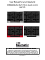
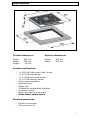
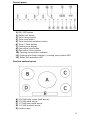
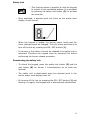
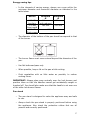
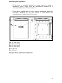
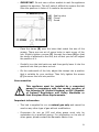
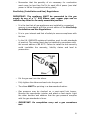
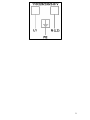
OMBRA6SS/BL/W/R
75 cm Touch control gas
hob
1 el
User Manual for your Baumatic
OMBRA6SS/BL/W/R 75 cm touch control
gas hob
NOTE: This User Instruction Manual contains important
information, including safety & installation points, which will
enable you to get the most out of your appliance. Please keep it
in a safe place so that it is easily available for future reference; for
you or any person not familiar with the operation of the appliance.
GS 24/06/11
2
Contents
Environmental note
4
Important safety information
5–7
Specifications
Product and aperture dimensions
Product specifications
Standard accessories
Electrical details
Gas details
Control panel
Gas hob surface layout
8 – 10
8
8
8
9
9
10
10
Using the gas hob
Before first use
Setting the time of day
Switching the hob on
Automatic ignition with flame failure device
Switching off a cooking zone
Residual heat indicator
Setting the burner shutoff time
Releasing a blocked burner
Safety lock
Deactivating the safety lock
Energy saving tips
Pan stand
11 - 17
11
11
12
12 – 13
13
13
14 – 15
15
16
16
17
17
Cleaning
Cleaning the hob top
After each use
Cleaning the hob burners
Maintaining the cast iron pan stands
18 - 19
18
18
18 - 19
19
Installation
Positioning
Unpacking the appliance
Installing the appliance
Gas connection
Ventilation requirements
Gas Safety (Installation and Use) Regulations
Gas Adjustment (Conversion to LPG)
Minimum flow adjustment for hob gas taps
Displaying the inner hob temperature
Display test procedure
Electrical connection
Replacing the mains supply cable
20
20
21
22
24
25
26
27
28
29
29
30
30
My appliance isn’t working correctly
Error codes
32 – 34
32 - 34
Contact details
35
- 31
- 21
- 24
- 25
- 26
- 28
– 29
- 31
3
Environmental note
o The packaging materials that Baumatic uses are environmentally
friendly and can be recycled.
o Please discard all packaging material with due regard for the
environment.
4
Important safety information
Your safety is of the utmost importance to Baumatic.
Please make sure that you read this instruction booklet
before attempting to install or use the appliance. If you
are unsure of any of the information contained in this
booklet, please contact the Baumatic Customer Care
Department.
General Information
o This appliance is designed for domestic household use and for
the cooking and frying of domestic foodstuffs.
o IMPORTANT: The adjacent furniture and all materials used in
the installation must be able to withstand a minimum
temperature of 85°C above the ambient temperature of the
room it is located in, whilst in use.
o Certain types of vinyl or laminate kitchen furniture are
particularly prone to heat damage or discolouration at
temperatures below the guidelines given above.
o Any damage caused by the appliance being installed in
contravention of this temperature limit, will be the liability of
the owner.
o Your new appliance is guaranteed against electrical or
mechanical defects, subject to certain exclusions that are noted
in Baumatic’s Conditions Of Guarantee. The foregoing does not
affect your statutory rights.
o The use of this appliance for any other purpose or in any other
environment without the express agreement of Baumatic Ltd.
will invalidate any warranty or liability claim.
o You should not use this appliance to store items on or as a work
surface.
o No modifications to the appliance are permitted by Baumatic Ltd.
o You should not store or place flammable or highly flammable
liquids/materials on top of or near the appliance. Items made
from aluminium, plastic or plastic film should also be kept away
from the appliance, as they may fuse to the surface.
o Repairs may only be carried out by Baumatic service
engineers or their authorised service agent.
5
Child Safety
o Baumatic strongly recommend that babies and young children
are prevented from being near to the appliance and not allowed
to touch the appliance at any time. During and after use, all
surfaces will be hot.
o If it is necessary for younger family members to be in the
kitchen, please ensure that they are kept under close supervision
at all times.
o Older children should only be allowed to utilise the appliance
when supervised.
General Safety
o The appliance should only be installed and connected by a
GASSAFE registered installer.
o Care should be taken to ensure that the units and work surfaces
that you build the appliance into, meet with the relevant
standards.
During use
o Any film or stickers that are present on the hob surface when it
is delivered should be removed before use.
o Care should be used when utilising the appliance, otherwise
there is a risk of burns being caused.
o You should not allow the electrical connection cables to come
into contact with the hob surface when it is hot or any hot
cookware.
o If fat and oil overheats, then it can ignite extremely quickly. For
this reason, when cooking with fat and oil the appliance should
not be left unattended.
o Make sure that all of the cooking zones are switched off after
use.
6
Cleaning
o Cleaning of the hob should be carried out on a regular basis.
o IMPORTANT: Before attempting to clean the appliance, it
should be disconnected from the mains and cool.
o Great care should be taken whilst using this appliance and when
following the cleaning procedure.
o You should not use a steam jet or any other high pressure
cleaning equipment to clean the appliance.
Installation
This appliance must be correctly installed by a
GASSAFE
registered
installer,
strictly
in
accordance with the manufacturer’s instructions
and the relevant British Standards. Please see the
specific section of this booklet that refers to
installation.
o Baumatic Ltd. declines any responsibility for injury or
damage, to person or property, as a result of improper
use or installation of this appliance.
o If the appliance is being used in a Leisure Accommodation
Vehicle, the requirements of N 721 MUST be followed.
o Baumatic Ltd. DO NOT recommend that this appliance is
installed on any type of marine vessel.
Declaration of conformity
This appliance complies with the following European Directives:
-2006/95/CE General regulations / Low tension
-2009/142/CE Concerning gas appliances
-1935/2004/CE 90/128/EEC This appliance is suitable to come in
contact with food
-2004/108/CE Electromagnetic compatibility
The manufacturer declares that the hob is built using certified
materials and requires the appliance to be installed in accordance with
the standards currently in force. This appliance must be used by a
trained person for domestic purposes only.
7
Specifications
Product dimensions:
Aperture dimensions:
Depth:
Width:
Height:
Depth:
Width:
500 mm
740 mm
50 mm
480 mm
560 mm
Product specifications:
o
o
o
o
o
o
o
o
o
o
o
1 x 3.80 kW triple crown (wok) burner
1 x 3.00 kW rapid burner
2 x 1.75 kW semi-rapid burner
1 x 1.00 kW auxiliary burner
Touch control operation
Electronic timer
Safety lock
5 Individual residual heat indicators
Automatic ignition
Heavy duty cast iron pan stand
Flame failure safety device
Standard accessories:
o Ceramic hob scraper
o LPG conversion kit
8
Electrical details
Rated Voltage:
Supply Connection:
Max Rated Inputs:
Mains Supply Lead:
220 – 240 Vac 50 - 60 Hz
3 A (double pole switched fused outlet with
3mm contact gap)
0.006
3 core x 0.75mm² (Type RR-F <HAR> marked)
Gas details
Connection:
Type:
Rp ½ (ISO R7)
Natural Gas (20.9 mbar)
Alternative LPG G30 (28-30 mbar)
For future reference please record the following information which can
be found on the rating plate and the date of purchase which can be
found on your sales invoice. The rating plate of your hob is located on
the underneath of the appliance. Therefore it is a good idea to record
this information before you install your appliance.
Model Number
……………………………….
Serial Number
……………………………….
Date of Purchase
……………………………….
9
Control panel
1) ON / OFF button
2) Safety lock button
3) Timer minus button
4) Timer plus button
5) Timer and clock selection button
6) Timer / clock display
7) Cooking zone display
8) Gas control plus button
9) Gas control minus button
10) Cooking zone position indicator
11) Cooking zone timer selection / cooking zone position LED
12) Safety lock activation LED
Gas hob surface layout
A) 3.80 kW triple crown (wok burner)
B) 3.00 kW rapid burner
C) 1.75 kW semi-rapid burner
D) 1.00 kW auxiliary burner
E) Control panel
10
Using the gas hob
Before first use
IMPORTANT: You should clean the hob surface (see
“Cleaning and maintenance” section).
Setting the time of day
Each time the power supply is cut off, the time displayed by the
hob clock must be reset.
o After initially powering the hob, the number 0.00 will appear on
the timer display (6) with a flashing decimal point.
o In this mode, the hob is in stand-by and can only be switched on
by pressing the ON / OFF button (1).
o After pressing the power button, the time can be set. If the time
is not set, the clock will continue to automatically count the time
that has passed from when it was connected to the mains power
supply.
o To set the time, press the timer button (5) and safety lock
button (2) simultaneously for at least three seconds.
o Once these buttons are pressed, the hour digit will start to flash.
You can then adjust the hour using the timer plus (4) and minus
(3) buttons. The variation will be continuous if the button is held
down.
o Press the timer button (5) again to confirm the hour and the
minute digit will start to flash.
o To program the minutes follow the same steps outlined above.
Press the timer button (5) to store the set time.
11
Switching the hob on
o The hob can be switched on by pressing the ON / OFF button (1)
and holding it down for at least two seconds.
o Once activated, the five displays related to the burners will show
level 0, which indicates that the cooking zones are off.
o If additional operations are not performed after the hob is
switched on, it will automatically switch off after one minute.
Automatic ignition with flame failure safety device
The appliance is fitted with a flame failure safety device on the burner,
which is designed to stop the flow of gas to the burner head in the
event of the flame going out.
To ignite a burner:
o Press down and release the plus button (8) for the selected
burner and within three seconds press the plus button again.
o Following this, the cooking zone will ignite at level 7, which is the
maximum power level.
o The ignition of the cooking zone is also signalled by the
corresponding LED indicator (11) that will remain active for the
entire period that the burner is in use.
To adjust the burner’s power level:
o Once the burner is lit you can select the gas flow rate by using
the relevant plus and minus buttons.
o The burner is set automatically to the maximum level of 7 when
the burner is lit. To decrease it, press the relevant minus button.
12
o To obtain a continuous variation of the power level simply hold
down the plus or minus button of the selected cooking zone and
release it once the display shows the desired level. You can
choose between 1 – 7 levels.
o By selecting level 0, you will switch the burner off.
Switching off a cooking zone
o To switch off a cooking zone press and hold the relevant plus
and minus buttons simultaneously for a moment.
o Alternatively, to switch off all the burners at the same time,
simply press the ON / OFF button (1) and the hob will return to
stand-by mode.
Residual heat indicator
o After a zone is switched off, the corresponding
cooking zone indicator will show a flashing letter
“H”. This means that the zone temperature
exceeds 60°C and therefore it is still hot enough to
cause injury.
o When the zone temperature drops below 60°C, the letter “H” will
go out.
o IMPORTANT: The residual heat indicator will disappear if the
mains supply to the product is cut.
o IT IS STILL POSSIBLE TO BURN YOURSELF ON A HOB
ZONE, EVEN WHEN THE TEMPERATURE OF IT HAS
DROPPED BELOW 60°C.
13
Setting the burner shutoff time
o With the timer function (5) a maximum time can
be set after which a burner will switch off.
o Each burner can be timed independently of the
others and can be set either when the cooking
zone is on or off.
o The countdown will start immediately after the set time is
confirmed. If no burner is being timed the hob will switch off
automatically after 4 hours. Before setting a timer function,
please light any burners that you wish to link to the timer.
o To set a burner time, press the timer button (5). The timer
display (6) will show 0.00. The LED zone of the control panel
shows the position of each burner (11), the LED for burner 1 will
switch on and start to flash. This means that burner 1 is selected
and is ready to be programmed.
o Press the timer plus (4) or minus (3) button to select a different
burner to programme. Once identified by the corresponding LED,
press the timer button (5) again to confirm.
o Following this, the first number of the timer display (6), which
indicates the hours, will start to flash. Press the timer plus and
minus to increase or decrease the operating hours from a
minimum of 0 to a maximum of 9. The variation will be
continuous if the buttons are held down.
o Once the desired number is reached, press the timer button (5)
to confirm and the minute numbers will start to flash. To set the
minutes follow the same steps used for the hours. The minutes
can be set between a minimum of 01 and a maximum of 59.
o Each burner can be programmed for a maximum time of 9 hours
and 59 minutes.
o To confirm the time on the display, press the timer button (5).
o If you wish to programme further burners, then follow the same
process again.
o When programming the timer, the current setting can be reset at
any time by pressing the relevant plus and minus buttons
simultaneously. Following this, only the burner indicators that
have an active timer will remain on and flash.
14
o It is possible to return to the timer programming mode at any
time to view the time remaining until it will shut off or to change
the current settings, simply by pressing the timer button (5) and
using the control buttons to select the desired burner. You can
then follow the same procedure as outlined above.
o If in programming mode no button is pressed for more than ten
seconds, the setting procedure will be stopped automatically and
the main display will return. Any settings being modified for the
selected burner will not be lost and the relative timer will be
active.
o When the timer is finished, the relevant burner will be shut off
and an acoustic signal will go off for thirty seconds. You can
switch this off by pressing the timer button (5).
o If you switch off a burner manually, the relative timer set will
also be deactivated.
o If you press the ON / OFF button (1) at any time, all the timers
will be deactivated.
Important: Never leave the hob unattended during operation at
any time.
Releasing a blocked burner
o The individual burners can be shut down and in this instance the
corresponding display will show the letter “b” (blocked).
o Burners will be shut down if the hob attempts to ignite the
burner three times without success. In this circumstance you
should switch the appliance off at the mains and check that the
sparking plug and the ignition sensor are clean. Otherwise
contact the Baumatic Customer Care Department.
o The burner can be released by pressing the relevant minus
button and the safety lock button (2) simultaneously for at least
two seconds.
o When released, the burner will be restored to level 0 and is
ready to be reignited.
If the release procedure is repeated for five consecutive times
during a fifteen minute period, the display will show “FLT06”
and the release procedure cannot be repeated for an additional
fifteen minutes. If a burner keeps locking then please contact
the Baumatic Customer Care Department.
15
Safety lock
o This function makes it possible to lock the keypad
to protect it from accidental actions. It is activated
by pressing the safety lock button (2) for at least
two seconds.
o Once activated, a decimal point will show on the power level
display of each burner.
o When the keypad is locked, the burner power levels and the
timer settings cannot be changed. The only action permitted is to
turn off the hob by pressing the ON / OFF button (1).
o If a burner is shut down it cannot be released if the safety lock is
activated. Therefore the keypad must be unlocked first before
performing the burner release procedure.
Deactivating the safety lock
o To unlock the keypad, press the safety lock button (2) and the
plus button (8) for burner 1 simultaneously for at least two
seconds.
o The safety lock is deactivated when the decimal point in the
burner power level display turns off.
o By turning off the hob by pressing the ON / OFF button (1) and
turning it on again, the keypad lock is automatically deactivated.
16
Energy saving tips
o In the interests of saving energy, always use a pan within the
minimum diameter and maximum diameter as indicated in the
table below:
Burner
1.00 kW
Auxiliary
1.75 kW
Semi-rapid
3.80 kW
Triple crown
Maximum
Minimum
Ø
Ø
60 mm
140 mm
(with reducer)
160 mm
200 mm
240 mm
o The diameter of the bottom of the pan should correspond to that
of the burner.
o The burner flame must never extend beyond the diametre of the
pan.
o Use flat bottomed pans only.
o When possible, keep a lid on the pan whilst cooking.
o Cook vegetables with as little water as possible, to reduce
cooking times.
IMPORTANT: Always place pans centrally over the hob burners and
position them so that the handles cannot get accidentally caught or
knocked off. You should also make sure that the handle is not over one
of the other hob burner flames.
Pan stand
o The pan stand is designed to make the appliance easy and safe
to use.
o Always check the pan stand is properly positioned before using
the appliance. Also check the protective rubber feet are all
present and correctly positioned.
17
Cleaning
Cleaning operations must only be carried out when
the hob is cool.
The appliance should be disconnected from your
mains supply before commencing any cleaning
process.
Cleaning the hob top
Any residues that are left on the hob top surface from cleaning
agents will damage it. You should remove any residues with
warm soapy water.
Abrasive cleaners or sharp objects will damage the hob surface;
you should clean it using warm soapy water.
Although it is easier to clean some deposits whilst the
hob surface is still warm. Make sure that the hob surface,
pan supports and hob burners have all cooled sufficiently
before you attempt to touch them.
After each use
o Remove the pan stands and wipe the appliance over with a soft,
damp cloth that has been put into warm soapy water. The cloth
should be wrung out after being taken out of the soapy water.
o Dry the appliance by rubbing the surface with a soft, clean cloth.
o We would recommend that an appropriate stainless steel cleaner
and polish is regularly used on the stainless steel surfaces of this
appliance (OMBRA6SS only).
Cleaning the hob burners
The hob burners should be cleaned once a week or more frequently if
they get soiled.
o IMPORTANT: Make sure that the hob surface, pan stands and
hob burners have cooled before you attempt to touch them.
o Remove the hob burners by pulling them upwards and away
from the hob top.
o Soak them for about ten minutes in hot water and a little
detergent.
18
o After cleaning and washing them, wipe and dry them carefully.
o Before placing the burners back on the hob top, make sure that
the gas jet is not blocked.
o IMPORTANT: Make sure that you reassemble the burners in the
original way.
Maintaining the cast iron pan stands
o IMPORTANT: Make sure that the hob surface and pan stands
have cooled before you attempt to touch them.
o Wipe the pan stands over with a soft, damp cloth that has been
put into warm soapy water. The cloth should be wrung out after
being taken out of the soapy water.
o Using a paper towel, thoroughly dry the pan stands.
o To maintain the appearance of the cast iron pan stands, we
would recommend that you rub a small amount of olive oil into
the pan stands, after you have finished cleaning them.
19
Installation
The installation must be carried out by a GASSAFE
registered installer, in accordance with the current
version of the following.
o Gas Safety Regulations (Installation & Use)
o Building Regulations (issued by the Department of Environment)
o Building Standards
Department)
(Issued
by
the
Scottish
Development
o IEE Wiring Regulations
o Electricity at Work Regulations BS 6172
o Installation of Domestic Gas Cooking Appliances (if necessary,
BS 5482 Installation of Domestic LPG Appliances)
o BS 5440 Installation of Flues and Ventilation for Gas Appliances
o Baumatic Ltd Installation Instructions
Positioning
The adjacent furniture must be able to withstand a
minimum temperature rise of 85°C above the ambient
temperature of the room it is located in, during
periods of use.
o This appliance can be located in a kitchen, a kitchen diner or a
bed sitting room. IMPORTANT: The appliance must not be
installed in a bathroom or shower room.
This appliance is classified as Class 3 and therefore is to be built into a
kitchen unit (depending on size) or 600mm worktop, providing the
following minimum distances are allowed:
o The edges of the hob must be a minimum distance of 55 mm
from a side or rear wall.
o 700 mm between the highest point of the hob surface (including
the burners) and the underside of any horizontal surface directly
above it.
o 400 mm between the hob surface, providing that the underside
of the horizontal surface is in line with the outer edge of the hob.
20
If the underside of the horizontal surface is lower than 400 mm,
then it must be at least 50 mm away from the outer edges of
the hob.
o 50 mm clearance around the appliance and between the hob
surface and any combustible materials.
Unpacking the appliance
When unpacking the appliance please check that the following items
are contained within the packaging:
1 x Baumatic hob
5 x Pan stands
Burner assemblies
Instruction manual
Baumatic warranty card
Fixing screws
Clamps
Sealing strip
LPG conversion jets
Self-adhesive label for amending the gas category on the appliance’s
rating plate (required if the LPG conversion jets are used).
21
Installing the appliance
o If the hob is installed without an oven below it, place a
separating panel made from an appropriate material at a
minimum distance of 10 mm below it.
o If the hob is installed over an oven, place a separating panel at a
minimum distance of 15 mm below it and follow the
manufacturer’s instructions of the oven.
F = 10 mm (min)
H = 50 mm (min)
G = 15 mm (min)
C = 30 mm (min)
D = 120 cm²
E = 180 cm²
Always allow sufficient ventilation.
22
o Cut a hole in the worktop that corresponds with the diagram
below:
o Carefully turn the hob upside down and place it on a cushioned
mat.
o Apply the sealing strip (A) provided around the edge of the
appliance.
o The protective covering must be removed from both sides.
o Do not leave a gap in the sealing agent or overlap the thickness.
23
o IMPORTANT: Do not use a silicon sealant to seal the appliance
against the aperture. This will make it difficult to remove the hob
from the aperture in future if it needs to be serviced.
(A)
(B)
(C)
Sealing strip
Clamp
Screw
o Place the clamp (B) over the holes that match the size of the
screws. There are one set of screw holes in each corner of the
hob. Slightly tighten a screw (C) through the clamp (B) so that
the clamp is attached to the hob, but so that you can still adjust
the position of it.
o Carefully turn the hob back over and then gently lower it into the
aperture hole that you have cut out.
o On the underneath of the hob, adjust the clamps into a position
that is suitable for your worktop. Then fully tighten the screws
(C) to secure the hob into position.
Gas connection
This appliance must be installed by a competent
person in accordance with the current versions of
the following UK (United Kingdom) or ROI (Republic
of Ireland) Regulations and Safety Standards or
their European Norm Replacements.
Important information
o This hob is supplied to run on natural gas only and cannot be
used on any other type of gas without modification.
o Conversion for use on LPG and other gases must only be
undertaken by a qualified person. For information on the use of
other gases, please contact the Baumatic Advice Line.
24
o The hob must be installed by a qualified person, in accordance
with the current edition of the Gas Safety (Installation and Use)
(Amendment) Regulations and the relevant building/I.E.E.
Regulations.
o Failure to install the appliance correctly could invalidate
Baumatic’s guarantee and lead to prosecution under the
regulations quoted above.
o In the UK, GASSAFE registered installers are authorised to
undertake the installation and service work, in compliance with
the above regulations.
Ventilation requirements
o The room containing the hob should have an air supply in
accordance with the current edition of BS 5440: Part 2:
o The room must have opening windows or equivalent; some
rooms may also require a permanent vent.
o If the room has a volume between 5 and 10m³, it will require an
air vent of 50cm² (effective area). Unless it has a door which
opens directly to the outside.
o If the room has a volume of less than 5m³, it will require an air
vent of 100cm² (effective area).
o If it is installed in a room with a volume that exceeds 11m³, then
no air vent is required.
o If there are any other fuel burning appliances in the same room
the current edition of BS 5440: Part 2: should be consulted to
determine air vent requirements.
o Ensure that the room containing the hob is well ventilated, keep
natural ventilation holes or install a mechanical ventilation device
(mechanical cooker hood).
o Prolonged intensive use of the appliance may call for additional
ventilation, either by the opening of a window, or by increasing
the level of the mechanical ventilation device (where present).
o This hob is not fitted with a device for discharging the products
of combustion. Ensure that the ventilation rules and regulations
are followed.
o The walls behind and near the hob should be resistant to heat,
steam and condensation.
25
o Remember that the quantity of air necessary for combustion
must never be less than 2m³/h for each kW of power (see total
power in kW on the appliance rating plate).
Gas Safety (Installation and Use) Regulations
IMPORTANT: The appliance MUST be connected to the gas
supply by use of a ½” BSP Elbow, seal, copper pipe and an
isolation tap fitted in an easily accessible position.
o It is the law that all gas appliances are installed by competent
persons in accordance with the current edition of the Gas Safety
Installation and Use Regulations.
o It is in your interest and that of safety to ensure compliance with
the law.
o In the UK, GASSAFE registered installers work to safe standards
of practice. The cooker must also be installed in accordance with
the current edition of BS 6172. Failure to install the hob correctly
could invalidate the warranty, liability claims and lead to
prosecution.
o Put the gas seal into the elbow.
o Fully tighten the elbow and seal onto the gas rail.
o The elbow MUST be pointing in a downwards direction.
o Gas pressure may be checked on a semi-rapid hob burner.
Remove the appropriate injector and attach a test nipple. Light
the other burners and observe that the gas pressure complies
with the gas standards in force.
o IMPORTANT: On completion carry out a gas soundness
test.
26
Gas adjustment (Conversion to LPG)
All work must be
registered engineer.
carried
out
by
a
GASSAFE
IMPORTANT: Always isolate the hob from the electricity supply
before changing the injectors and/or adjusting the minimum
flow of the burners.
o Remove the pan-stands, burners and
flame spreaders (A).
o Unscrew the injector (B) and replace it
with the stipulated injector for the new gas
supply (see table below).
GENERAL INJECTORS TABLE
Kind of gas Nozzle
Burners
Power
Power
Mm/100
Max (Watts) Min (Watts)
135
Wok
3800
1500
Natural
115
Rapid
3000
750
97
Semi-rapid
1750
440
72
Auxiliary
1000
300
L.P.G
98
Wok
3800
1700
Butane
85
Rapid
3000
900
Propane
65
Semi-rapid
1750
500
50
Auxiliary
1000
370
o Reassemble all the burners carefully; in particular you should
make sure that the flame spreader is correctly placed on the
burner.
27
o IMPORTANT: The minimum flow adjustment process must
be completed before the appliance is next used.
o To activate the procedure for selecting the combustible gas
used, turn on the hob but keep the burners off.
o Press the minus button for burner 1, minus button for burner
2 and the minus button for the timer all at the same time for
at least two seconds.
o When the procedure is activated all burner power level
displays will turn off and the timer display will show “Met” or
“Lpg” depending on the current configuration.
o By pressing the timer plus and minus buttons, the desired gas
can be selected.
o To confirm the gas and end the procedure, press the timer
button. It will return to the initial configuration with all
displays at level 0 and the time displayed on the timer.
o Any previously programmed timers will be cancelled.
Minimum flow adjustment for the hob gas tap.
All work must be
registered engineer.
carried
out
by
a
GASSAFE
o This procedure is activated by pressing the plus and minus
buttons for burner 1 together with the plus and minus buttons
for burner 5 in a continuous manner for three seconds. All the
burners must be off.
o The activation of the procedure is signalled on the display
with the word “MIN”.
o Select the burner to regulate by pressing the minus and plus
buttons for the timer and press the timer button to confirm.
o The selected burner will ignite at the minimum level and it will
be possible to increase or decrease the flow rate to the
minimum level using the plus and minus buttons for the
relevant burner.
28
o During the regulation procedure, the power level display will
indicate if the set minimum corresponds to the factory
setting, otherwise a flashing value
or
will be
displayed if the gas flow rate is higher or lower than the
presetting.
o To confirm the desired minimum flow rate, press the timer
button. The word “MIN” will remain displayed and no LED
flashes, therefore you can programme, if desired, the
minimum flow rate for another burner by pushing the timer
plus and minus buttons and following the steps above.
o To exit the procedure, press the timer button.
o The minimum flow rate levels are acquired and stored by the
appliance and are used for normal hob use.
Displaying the inner hob temperature
o The electronic card has a temperature sensor that is used to
display the temperature inside the hob directly on the timer
display.
o It can be activated by pressing the plus and minus buttons for
burner 1 at the same time as the plus and minus buttons for the
timer continuously for at least three seconds.
o In this condition, the timer button cannot be used for settings
related to programming the burner shutoff time.
o The same key sequence used to activate the display of the inner
temperature must be used to stop it.
Display test procedure
o It is possible to constantly turn on all display LED’s by pressing
the plus and minus buttons for burner 1 at the same time for
one second within five seconds of the appliance being electrically
powered.
o This function is useful to check the functionality of all LED’s and
to align the serigraphy of the glass with the displays themselves.
o Once five seconds have passed since turning on the appliance,
this procedure can no longer be activated.
o If the procedure is activated, the appliance keypad is
deactivated, therefore to exit the procedure the voltage must be
disconnected from the appliance.
29
Electrical connection
This appliance must be installed by a qualified
person in accordance with the latest edition of the
I.E.E. Regulations and in compliance with Baumatic’s
instructions.
Before connecting the appliance, make sure that the supply voltage
marked on the rating plate corresponds with your mains supply
voltage.
o Cable type: H05 RRF 3 core x 0.75 mm² (Type RR-F <HAR>
marked).
o The mains supply cable is supplied with this product.
Replacing the mains supply cable
If the mains supply cable is damaged, then it must be replaced by an
appropriate replacement which can be obtained from the Baumatic
Spares Department.
The mains supply cable should be replaced in accordance with the
following instructions:
o Switch the appliance off at your mains supply.
o Open the box of the supply board.
o Unscrew the clamp fixing the cable.
o Replace the cable with one of the same length and in accordance
with the specification given above.
o The “green-yellow” earth wire must be connected to the terminal
. It must be about 20 mm longer than the live and
marked
neutral wires.
o The “blue” neutral wire must be connected to the terminal
marked with letter (N) - the live wire must be connected to the
terminal marked with letter (L).
30
31
My appliance isn’t working correctly
Error codes
o The burners will be shut down when the hob has tried three
consecutive times to ignite the burner without success.
Solution: Execute the following key sequence for release:
o The burner can be released by pressing the relevant minus
button and the safety lock button (2) simultaneously for at least
two seconds.
o When released, the burner will be restored to level 0 and is
ready to be reignited.
For suggestions regarding why a burner may fail to ignite please see
the table below:
Reason
There is no gas.
Incorrect connection to the
earthing system.
The electrode does not find
the connection.
Solution
Check that the tap is open.
Check the connections.
Check that the burner cover is
positioned properly in its seat.
o The electronic circuit detects the presence of an abnormal or
parasite flame.
o The electronics detect the presence of the flame before having
opened the gas valve and enters a “parasite flame” state and a
flashing “F” appears on the display. If this situation continues for
more than ten seconds, the burner will shut down.
o Another condition for the parasite flame can be a failed valve
seal. This is the condition of wanting to ignite burner A but there
is a leak in burner B so both burners will be ignited.
o Detecting the presence of a parasite flame for more than ten
seconds in a burner for which ignition is not requested, the
electronics will create a general shutdown state.
Solution: Contact the Baumatic Ltd customer care helpline.
32
o The burner was shut down more than five times in fifteen
minutes or the release procedure was repeated for five
consecutive times during a fifteen minute period.
Solution: Wait fifteen minutes before carrying out the key release
sequence:
o The burner can be released by pressing the relevant minus
button and the safety lock button (2) simultaneously for at least
two seconds.
o When released, the burner will be restored to level 0 and is
ready to be reignited.
o All the burners are shut down at the same time e.g. as in error
code “b”.
Solution: Execute the following key sequence for the release:
o The burner can be released by pressing the relevant minus
button and the safety lock button (2) simultaneously for at least
two seconds.
o When released, the burner will be restored to level 0 and is
ready to be reignited
o The keypad sensitivity has a momentary calibration error.
Solution: Disconnect the hob from the power supply network and then
reconnect it. The hob will perform a self-calibration of the keypad and
all LED’s will remain on for a few seconds. Do not touch the hob for
a few minutes.
o Once any error code appears on the display and the appliance is
disconnected from the electricity supply and then reconnected,
this code will appear on the display instead. It is a generic
anomaly and merely indicates that something has gone wrong.
Solution: Carry out the following key sequence for the burner
shutdown release:
33
o The burner can be released by pressing the relevant minus
button and the safety lock button (2) simultaneously for at least
two seconds.
o When released, the burner will be restored to level 0 and is
ready to be reignited
o If any of these error codes appear on the display, they cannot be
reset with a command sequence.
Solution: Contact the Baumatic Customer Care Department.
IMPORTANT: If your appliance appears not to be
operating correctly, then you should disconnect it
from your mains supply and then contact the
Customer Care Department on telephone number
(0118) 933 6911.
DO NOT ATTEMPT TO REPAIR THE APPLIANCE
YOURSELF.
Please note that if an engineer is asked to attend whilst the product is
under guarantee and finds that the problem is not the result of an
appliance fault, then you may be liable for the cost of the call out
charge.
The appliance must be accessible for the engineer to perform
any necessary repair. If your appliance is installed in such a
way that an engineer is concerned that damage will be caused
to the appliance or your kitchen, then he will not complete a
repair.
This includes situations where appliances have been tiled in,
sealed in with sealant, have wooden obstructions placed in
front of the appliance, like plinths. Or any installation other
than the one specified by Baumatic Ltd. has been completed.
Please refer to the conditions of guarantee that appear on the
warranty card that you receive with the appliance.
IMPORTANT: Baumatic Ltd. operates a policy of continuous
improvement and reserves the right to adjust and modify its
products without prior notification.
34
United Kingdom
Baumatic Ltd.,
Baumatic Buildings,
6 Bennet Road,
Reading, Berkshire
RG2 0QX
United Kingdom
Sales Telephone
(0118) 933 6900
Sales Fax
(0118) 931 0035
Customer Care Telephone
(0118) 933 6911
Customer Care Fax
(0118) 986 9124
Spares Telephone
(01235) 437244
Advice Line Telephone
(0118) 933 6933
E-mail:
[email protected]
[email protected]
[email protected]
[email protected]
Website:
www.baumatic.co.uk
Republic of Ireland
Service Telephone
1-890 812 724
Spares Telephone
091 756 771
Czech Republic
Baumatic CR s.r.o.
Lípovà 665
460 01 Liberec 4
Czech Republic
+420 483 577 200
www.baumatic.cz
Slovakia
Baumatic Slovakia, s.r.o.
Galvániho 7/D
Slovakia
+421 255 640 618
Germany
Baumatic Gmbh
Lilienthalstrasse 1
320 52 Herford
Deutschland
+49 5221 694 99-0
www.baumatic.de
Italy
Baumatic Italia S.R.L.
Via Galvani N.3
35011 Campodarsego (PD)
+3904 9920 2297
www.baumatic.it
Holland
Baumatic Benelux B.V.
Grindzuigerstraat 22
1333 MS ALMERE
Nederland
+3136 549 1555
www.baumatic.nl
35
36