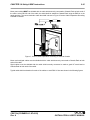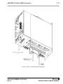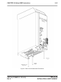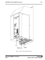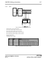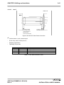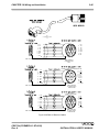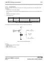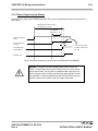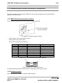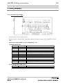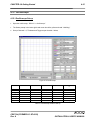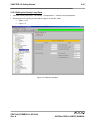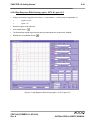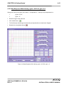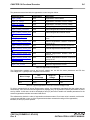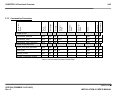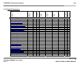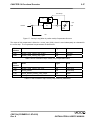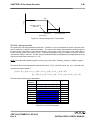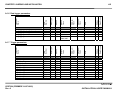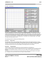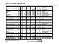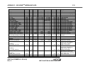
1
DS2110 DIGITAL CONTROLLER INSTALLATION & USER’S MANUAL Document No.: CDS7324 (formerly LSF-0819) Revision: A Date: May 2011 INDUSTRIAL CONTROLS DIVISION TABLE OF CONTENTS T/C -1 TABLE OF CONTENTS CHAPTER 1.0 OVERVIEW............................................................................................................. 1.1 Introduction ...................................................................................................................... 1.2 DS2110 Models................................................................................................................. 1.3 Environmental Specifications ......................................................................................... 1.4 Design Standards............................................................................................................. 1.5 Power Ratings Specifications.......................................................................................... 1.6 General functional specifications ................................................................................... CHAPTER 2.0 SAFETY & EMC INSTRUCTIONS.......................................................................... 2.1 General.............................................................................................................................. 2.2 Safety Regulations............................................................................................................ 2.3 Electromagnetic Compatibility........................................................................................ 2.4 UL Requirements ............................................................................................................. CHAPTER 3.0 WIRING AND INSTALLATION............................................................................... 3.1 System Components........................................................................................................ 3.2 Equipment Mounting........................................................................................................ 3.3 Power Dissipation ............................................................................................................ 3.4 DS2110 Connector Terminals ......................................................................................... 3.5 General System Wiring Guidelines................................................................................. 3.6 Sequence of Component Wiring Recommendations .................................................... 3.7 Three Phase AC Mains Power Source Configuration ................................................... 3.8 24V Backup Connection .................................................................................................. 3.9 Internal/External Regeneration (Regen) Resistors – Configurations .......................... 3.10 Motors – Installation ...................................................................................................... 3.11 DS2110 Control Inputs and Outputs............................................................................. 3.12 Communication Interface Wiring and Configuration .................................................. 3.13 Wiring Summary............................................................................................................. CHAPTER 4.0 GETTING STARTED .............................................................................................. 4.1 Introduction ...................................................................................................................... 4.2 Initial Preparation ............................................................................................................. 4.3 Power Supply ................................................................................................................... 4.4 Installing Windrive ........................................................................................................... 4.5 Controller Access ............................................................................................................ 4.6 Motor Selection ................................................................................................................ 4.7 Regen Resistor Configuration ........................................................................................ 4.8 Acceleration Limits .......................................................................................................... 4.9 Parameter Utilities............................................................................................................ 4.10 Status and Faults ........................................................................................................... 4.11 High Power Application ................................................................................................. 4.12 Autophasing.............................................................................................................. ...... 4.13 Torque Mode Enable ...................................................................................................... 4.14 Velocity Mode Enable .................................................................................................... 4.15 Oscilloscope................................................................................................................... 4.16 Power Down Sequence.................................................................................................. CDS7324 REV. A 1-1 1-1 1-2 1-4 1-5 1-6 1-9 2-1 2-1 2-2 2-12 2-22 3-1 3-1 3-5 3-15 3-16 3-20 3-22 3-23 3-29 3-32 3-36 3-49 3-54 3-55 4-1 4-1 4-1 4-1 4-2 4-3 4-4 4-6 4-8 4-9 4-10 4-11 4-12 4-13 4-14 4-15 4-20 INSTALLATION & USER’S MANUAL TABLE OF CONTENTS T/C -2 TABLE OF CONTENTS CDS7324 REV. A CHAPTER 5.0 FUNCTIONAL OVERVIEW..................................................................................... 5.1 Introduction ...................................................................................................................... 5.2 DS2110 Conventions........................................................................................................ 5.3 Power Interface Section................................................................................................... 5.4 Motor Configuration......................................................................................................... 5.5 Resolver Input .................................................................................................................. 5.6 Encoder Input ................................................................................................................... 5.7 Commutation Module....................................................................................................... 5.8 Position Feedback............................................................................................................ 5.9 Velocity Feedback ............................................................................................................ 5.10 Input and Output Functional Description..................................................................... 5.11 Control Loops................................................................................................................. 5.12 Drive Monitoring & Fault Detection .............................................................................. 5.13 Self Protection ................................................................................................................ 5.14 Parameter Storage ......................................................................................................... 5-1 5-1 5-1 5-2 5-8 5-13 5-16 5-21 5-24 5-25 5-26 5-34 5-52 5-66 5-67 APPENDIX A – DATA LOGGER .................................................................................................... A-1 APPENDIX B – GUI ........................................................................................................................ B.1 Introduction...................................................................................................................... B.2 Getting Started/Common Features ................................................................................ B-1 B-1 B-2 APPENDIX C – RESTART INTERLOCK CIRCUITS...................................................................... C.1 Intended Application ....................................................................................................... C.2 Restart Interlock Function .............................................................................................. C.3 Safety Requirements ....................................................................................................... C.4 Restart Interlock Circuit .................................................................................................. C.5 Restart Interlock Connections........................................................................................ C.6 Safety Relays – Technical Data ...................................................................................... C.7 Application Example ....................................................................................................... C.8 Checking the Restart Interlock ....................................................................................... C.9 External Consistency Checks ........................................................................................ C.10 Installation and Routine Test........................................................................................ C-1 C-1 C-2 C-4 C-5 C-7 C-9 C-10 C-13 C-14 C-15 APPENDIX D – MEZZANINE CARD INSTALLATION ................................................................... D-1 APPENDIX E – ANALOG I/O MEZZANINE CARD ........................................................................ E.1 Introduction...................................................................................................................... E.2 Overview........................................................................................................................... E.3 Configurations ................................................................................................................. E.4 Analog I/O......................................................................................................................... E.5 SSI Interface ..................................................................................................................... E.6 Simulated Encoder/Resolver .......................................................................................... E.7 PLC Master – DS2110 Slave Arrangement..................................................................... E.8 Noise Reduction .............................................................................................................. E-1 E-1 E-1 E-1 E-2 E-4 E-5 E-7 E-7 INSTALLATION & USER’S MANUAL TABLE OF CONTENTS T/C -3 TABLE OF CONTENTS CDS7324 REV. A APPENDIX F – DEVICENET™ MEZZANINE CARD...................................................................... F.1 Connector ......................................................................................................................... F.2 Network Status................................................................................................................. F.3 Available Objects ............................................................................................................. F.4 MacID and Baud Rate ...................................................................................................... F.5 Initial Motion Setup .......................................................................................................... F.6 Fieldbus Scaling Factors................................................................................................. F.7 Units .................................................................................................................................. F.8 PARAM UPDATE in .......................................................................................................... F.9 Implicit I/O......................................................................................................................... F.10 Parameter List ................................................................................................................ F-1 F-1 F-1 F-1 F-2 F-2 F-2 F-3 F-3 F-3 F-4 APPENDIX G – ETHERNET MEZZANINE CARD.......................................................................... G.1 Introduction ..................................................................................................................... G.2 Modes of Operation......................................................................................................... G.3 Changing IP Address for Ethernet Device .................................................................... G.4 Changing Commands and Status Registers................................................................. G.5 Allen-Bradley RSLogix Configuration with DS2110 ..................................................... G-1 G-1 G-1 G-2 G-4 G-6 INSTALLATION & USER’S MANUAL CHAPTER 1.0 Overview 1-1 1.1 Introduction This section gives an overview of the available DS2110 models, ratings and general specifications. Detailed outlines of installation and wiring, functionality, user interfaces and other technical data are given in subsequent sections. CAUTION: Repairs or modifications to the product by anyone other than a Moog authorized repair facility may create unsafe operating conditions and will invalidate the product warranty. CDS7324 (FORMERLY LSF-0819) Rev. A INSTALLATION & USER’S MANUAL CHAPTER 1.0 Overview 1-2 1.2 DS2110 Models The DS2110 family is available in twelve base models, which cover a range of output current ratings. DS2110 Base Model Amplifier Current Rating Code Size Continuous (Arms) Maximum (Arms) Peak (A) G362-x03 µA or A 3 6.4 9 G362-x04 A 4 8.5 12 G362-x06 µA or A 6 16 22 G362-x08 A 8 16 22 G362-010 B 10 29.7 42 G362-014 B 14 29.7 42 G362-020 C 20 31.8 45 G362-025 C 25 49.5 70 G362-030 C 30 63.6 90 G362-050 D 50 99.3 140 G362-060 D 60 127.6 180 G362-100 E 100 212.1 300 Table 1.1 DS2110 Family Models The DS2110 family uses a 14 character coding system to identify the unique attributes of each model. CDS7324 (FORMERLY LSF-0819) Rev. A INSTALLATION & USER’S MANUAL CHAPTER 1.0 Overview 1-3 Page Intentionally Blank CDS7324 (FORMERLY LSF-0819) Rev. A INSTALLATION & USER’S MANUAL CHAPTER 1.0 Overview 1-4 1.3 Environmental Specifications DS2110 Electronics Maximum temperature Storage: Transport: Surrounding air -25 C to 55 C (Class 1K4) -25 C to 70 C (Class 2K3) 0 C to 40 C Relative humidity: 5 % to 85 %, non-condensing, 1 g/m3 to 25 g/m3, in accordance with EN50178 class 3k3 Elevation: 1000m (3,300 feet); derate output 2% per 300m (1000 ft) above 1000m (3300 ft) Air pressure: 86 kPa to 106 kPa Type of protection: Components must be installed into an enclosure. The enclosure must provide at least IP54 per standard EN60529 or equivalent. Pollution degree: Drive is suitable for installation in a Pollution Degree 2 environment. Installed position: Vertical only. Overvoltage protection class: Category 2 per standard VDE0110 / IEC664 Noise: Overall noise depends on the user installation and cabinet. CDS7324 (FORMERLY LSF-0819) Rev. A INSTALLATION & USER’S MANUAL CHAPTER 1.0 Overview 1-5 1.4 Design Standards The DS2110 is CE-Marked under the EU's Low Voltage Directive. It has been designed to allow easy compliance of customer's machines under the EU's EMC Directive (measures as directed in this manual have to be taken to ensure EMC compliance). It is designed to the UL508C standard. The A size DS2110 units are UL recognized. The DS2110 A-D sizes are UL listed. The DS2110 has been designed to the following specific standards:IP Code EN 60529:1991 EMC EN 61800-3:1996 , EN 61800-3/A11:2000 (Second Environment) UL UL508C with reference to UL840 Table 1.2 DS2110 Design Standards CDS7324 (FORMERLY LSF-0819) Rev. A INSTALLATION & USER’S MANUAL CHAPTER 1.0 Overview 1-6 1.5 Power Ratings Specifications Model : G362-x 3Amp 6Amp 8Amp 10Amp 14Amp 20Amp 25Amp 30Amp 50Amp 60Amp 100Amp A.C. Mains Input Range Minimum 65Vac (110Vac -40%) Maximum 506Vac (440Vac +10%) Frequency Range 50 - 60Hz Internal Regeneration Power 150W Continuous Dissipation 50W 100W 2.6kW Peak Dissipation @ 230Vac 1.3Kw 1.3kW Peak Dissipation @ 400Vac 4.8kW 4.8kW 10.3kW N/A N/A N/A N/A N/A N/A N/A N/A External Regeneration Power Continuous Dissipation 50W 100W 200W 240W 250W 370W 370W 370W 750W 750W 1kW Peak Dissipation @ 230Vac 1.2Kw 1.2kW 2.8kW 6.6kW 4.4kW 12.0kW 12.0kW 12.0kW 14.4kW 14.4kW 37kW Peak Dissipation @ 400Vac 4.8kW 4.8kW 11.3kW 26.3kW 17.5kW 48.1kW 48.1kW 48.1kW 57.8kW 57.8kW 148kW Softstart Peak Inrush Current/Phase 30Apk D.C. Bus Overvoltage D.C. Bus Undervoltage Power Supply Fault Detection Bridge Temperature Fault Amplifier Short Circuit Protection 24V Logic Backup Monitoring Voltage Discharge after A.C Mains Removal Bleed Resistors across high voltage section. Table 1.3 DS2110 Power Ratings CDS7324 (FORMERLY LSF-0819) Rev. A INSTALLATION & USER’S MANUAL CHAPTER 1.0 Overview 1.5.1 1-7 Optional Control Logic Backup Power D.C. Bus Minimum Voltage (below which 24Vd.c. Control Logic Backup supply is needed) 24V Input 170Vd.c. (Generated from rectified 120Va.c.) 24Vd.c.± 10% 2.0A steady state Table 1.4 DS2110 Control Logic Backup Power Ratings An auxiliary 24V d.c. control logic backup supply is MANDATORY for the –x003 & -x006 variants of the DS2110 product family. The 24V Backup supply input is intended for use in the secondary of a Class 2 supply. Alternatively, it should be additionally fitted with a Listed Current limiting type fuse, rated 3A on the supply input to the device. 1.5.2 Power Amplifier All current ratings are specified in ampere r.m.s. unless otherwise stated. Power Amplifier Ratings: G362-x03 3A continuous/9A peak G362-x04 4A continuous/12A peak G362-x06 6A continuous/15A peak G362-x08 8A continuous/22A peak G362-010 10A continuous/42A peak G362-014 14A continuous/42A peak G362-020 20A continuous/45A peak G362-025 25A continuous/70A peak G362-030 30A continuous/90A peak G362-050 50A continuous/ 140A peak G362-060 60A continuous/ 180A peak G362-100 100A continuous/ 300A peak Table 1.5 DS2110 Power Amplifier Ratings Two levels of thermal protection which limit the peak current and the time for which it is available protect the DS2110 drives. These are: • • RMS Protection, Thermal Foldback. CDS7324 (FORMERLY LSF-0819) Rev. A INSTALLATION & USER’S MANUAL CHAPTER 1.0 Overview 1.5.4.1 1-8 RMS Protection The RMS protection acts to limit the current provided to the rated continuous current of the drive. Thus, a G362-x006 cannot supply, on average, greater than 6Acontinuous RMS to the motor. The current to the motor is averaged and if it exceeds the RMS rating, the drive limits the current command. If the controller continuously demands current greater than the drive capability, the RMS protection will limit the actual current supplied to the drive rating. The time for which peak current can be supplied is dependent on whether the motor is stalled or running. 1.5.4.2 Thermal Foldback Thermal foldback is implemented in the DS2110 drives to prevent the junction temperatures of the amplifier bridge IGBT’s exceeding their maximum rated temperature. The thermal foldback is based on a measure of the heatsink temperature and the mode in which the drive is operating (motor running or stalled). As the heatsink temperature increases, the peak current capability of the drive is reduced to ensure the IGBT die temperature cannot increase above the device maximum rating. For the DS2110 D size, a simple thermal shutdown is implemented. These drives will report an overtemperature fault once the measured heatsink temperature exceeds the maximum rating of the drive. CDS7324 (FORMERLY LSF-0819) Rev. A INSTALLATION & USER’S MANUAL CHAPTER 1.0 Overview 1-9 1.6 General Functional Specifications 1.6.1 • • • • Digital Inputs (J2A) 8 Digital Inputs, user configurable Digital Input 1 Dedicated to High Power Enable All Optically Isolated, 12…36V Input Range. 5k input impedance. STANDARD FUNCTION FIELDBUS OR INTERFACE SPECIFIC High Power Enable Input High Power Enable Input Auto / Manual Mode See Section 5.9 Torque / Velocity Mode Switch See Section 5.9 Brake Control See Section 5.9 CW Limit Switch See Section 5.9 CCW limit Switch See Section 5.9 Quick Stop See Section 5.9 Controlled Disable See Section 5.9 Table 1.6 DS2110 Digital Inputs Overview : Standard Configuration 1.6.2 • • • • • • Digital Outputs (J2B) 3 Digital outputs, user configurable All outputs are Optically Isolated. Nominal ratings of 6V to 32V, 250mA Protected for supply range of –40V to 40V Short-circuit & reverse polarity protected Off-state leakage current <100μA at 0V Standard Function Drive Enabled Limiting Function User defined Table 1.7 DS2110 Digital Outputs Overview CDS7324 (FORMERLY LSF-0819) Rev. A INSTALLATION & USER’S MANUAL CHAPTER 1.0 Overview 1.6.3 1-10 Standard I/O Relay output, contact ratings: 36V, 100mA max. Closed when drive is ready and has no faults. 2A, 24Vd.c. solid-state high-side drive for motor brake control. Switched under user control or DS2110 software control Resolver Encoder Types • SSI • Hiperface • Analogue encoders • Endat • NRZ serial RS232 Interface at 19200Baud Drive Ready (J2C) Brake Control (J2D) Motor Position Feedback Type (J3/J4) Communications Interfaces (J1) Table 1.8 DS2110 Standard I/O Summary 1.6.4 Variant Specific I/O Refer to the appendix for details on a specific fieldbus variant. CDS7324 (FORMERLY LSF-0819) Rev. A INSTALLATION & USER’S MANUAL CHAPTER 1.0 Overview 1-11 Page Intentionally Blank CDS7324 (FORMERLY LSF-0819) Rev. A INSTALLATION & USER’S MANUAL CHAPTER 2.0 Safety & EMC Instructions 2-1 2.1 General This user’s manual is intended to provide sufficient information on how to install Moog DS2110 electric motor systems. Section 2.2 covers Safety and System Safeguards. Section 2.3 covers Electromagnetic Compatibility (EMC). This user’s guide must be read and understood before applying power and operating the equipment described. This equipment must be installed and serviced only by duly qualified service personnel. All information in this manual is directed towards such persons only. Individuals responsible for the installation of the equipment described in this user’s guide must ensure; 1) only technically qualified individuals are employed to work on the installation, 2) these qualified individuals must have the accompanying documentation available at all times when working on the installation and are obliged to use this documentation in a consistent manner, and 3) work on, or close to, the installation is prohibited for non-technically qualified individuals Throughout this user’s guide may be found NOTES, CAUTIONS, and WARNINGS and CECompliance-Required. They are defined as follows: NOTES are general in nature and are intended to emphasise information. CAUTIONS are to alert personnel to actions that could cause equipment damage, resulting in the equipment becoming unsafe. WARNINGS serve to make personnel aware of potentially hazardous actions that may result in personal injury or death. Required for CE-Compliance CE-Compliance indicates where a particular application-related safety or EMC requirement is driven by the need for CECompliance of the DS2110 when installed in the system. Customers who do not need CE-Compliance on their machinery may choose not to implement these features. The DS2110 controller contains potentially lethal voltages. Extreme caution shall be observed whenever the equipment is in operation. Incorrect installation of the motor or the controller may cause damage to the equipment, serious personal injury or death. Consequently, the instructions in this user’s manual, as well as national and local rules and safety regulations must be complied with. CDS7324 (FORMERLY LSF-0819) Rev. A INSTALLATION & USER’S MANUAL CHAPTER 2.0 Safety & EMC Instructions 2-2 2.2 Safety Regulations 1. The DS2110 controller must be disconnected from all power if repair work is to be carried out. Check that the mains supply has been disconnected and that at least 5 minutes has passed for the A size (6 minutes for AE sizes), to allow for D.C. bus capacitors to discharge, before removing motor and mains connections. 2. Correct protective earthing of the equipment must be established, the user must be protected against supply voltage, and the motor must be protected against overload in accordance with applicable national and local regulations. 3. Do not remove the connections for the motor and mains supply while the DS2110 controller is connected to mains power. Check that the mains supply has been disconnected and that the necessary time has passed before removing motor and mains connections. Warning against unintended start The installation of safety interlocks, additional control and protection devices must be done in accordance with the relevant local safety requirements. Note that changes made through software can result in the motor starting suddenly. This user’s manual assumes that the user has a basic working knowledge of servo-drive products and the system motion controller. The user should provide the necessary additional training for ALL personnel working within or around the workcell. NOTE - These safety precautions are guidelines only and are not claimed to be comprehensive. The Moog Brushless Technology products described herein, in conjunction with the system controller, provide the capability for control of remote devices. Typically, these remote devices move at high speeds and exert considerable force. Like all mechanical systems and most industrial equipment, they must be treated with respect by both the machine integrator and user, and the operator. NOTE - This user’s guide defines “user” as the responsible person or company and “operator” as a person who starts, stops or monitors workcell operation. NOTE - This user’s guide should be read by all personnel who operate or who work within or near the workcell. Individuals responsible for the installation of the equipment described in this user’s guide must ensure that only technically qualified service personnel are employed to work on the installation. In the context of these safety instructions, skilled technical personnel means people who are familiar with the product, and have the necessary technical qualifications required for the performance of their functions. CDS7324 (FORMERLY LSF-0819) Rev. A INSTALLATION & USER’S MANUAL CHAPTER 2.0 Safety & EMC Instructions 2.2.1 2-3 System Safeguards a) General Safety Requirements Users are required to implement safety measures with all equipment, systems and installations into which the DS2110 Servo-drive are installed. In addition, safeguards must be an integral part of workcell design, installation, operator training and operator procedures where this equipment is used. Required for CE-Compliance Users are directed to refer to the European Union (EU) Machine Safety Directive: 98/37/EC and EU Low Voltage Directive 73/23/EEC (as amended by EU Directive 93/68/EEC) for essential health and safety requirements to be met. Furthermore the requirements of the EU EMC Directive: 89/336/EEC (as amended by EU Directive 92/31/EEC and 93/68/EEC) must be met by all equipment, systems and installations into which the DS2110 Controllers are installed. Users are recommended to refer to the latest publications of the European Union (EU) Commission and to local regulations for further information on the requirements of these Directives of the EU. Users are required to ensure that the drive is only connected to supply network configurations of the following types Required for CE-Compliance • TN Systems including TN-C, TN-S, TN-C-S • TT Systems. Connection to IT systems or corner-earthed TN systems is not allowed. Users should ensure the nature of the supply system is appropriate before connecting and operating the drive. b) Specific Safety Requirements The specific safety measures described below are required to be installed by the user into all equipment, systems and installations into which the DS2110 Series Controllers are installed. The user is required to provide safety interlocks to prevent unexpected restart during servicing of the DS2110 Controller and any equipment attached to or driven by these units. The DS2110 Servo-drives themselves must be installed in enclosures or cabinets that provide a degree of ingress protection against liquids and objects of at least IP54. These enclosures or cabinets must be accessible to technically qualified service or maintenance persons only. All external Regen (Regenerative circuit) resistors used with the DS2110 must be installed in enclosures which provide a degree of ingress protection against liquids and objects of at least IP22 and which are accessible to technically qualified service or maintenance persons only. Protection against electric shock must be maintained when installing these resistors. The equipment may have a continuous leakage current of more than 3.5 mA A.C. or 10 mA D.C. in normal use. The DS2110 must be permanently and reliably connected to Earth and all conductive parts in the IP54 rated enclosure or cabinet must be permanently connected to Earth. The impedance between the earth terminal and any accessible part of the enclosure or cabinet should be less than or equal to 0.1ohm. A D.C component can occur in the fault current in the event of a fault connection to earth. Only a residual-currentoperated protective device (RCD) of Type B is allowed. When the protection in installations with regard to indirect contact is achieved by means of an RCD, their appropriate function/combination shall be verified. All electrical supply wires and cables to this equipment must be installed in wireways (cable routings) which are smooth and free from sharp edges. CDS7324 (FORMERLY LSF-0819) Rev. A INSTALLATION & USER’S MANUAL CHAPTER 2.0 Safety & EMC Instructions 2-4 All external d.c. supply voltages used with the DS2110 Series Controllers must be derived from a Safety Extra Low Voltage (SELV) supply as defined by standard EN60950. Such SELV voltages do not exceed a value of 60 Vd.c. or 42.4 Va.c. peak under normal conditions and are supplied by circuits which are separated from all hazardous voltage conductors by permitted safety methods such as reinforced insulation. Required for CE-Compliance All external electrical wiring connected to this equipment must be colour coded in accordance with European Standard EN 60204-1 requirements. All wires and cables entering and leaving the IP54 rated enclosures or cabinets containing the DS2110 Controllers and Regen resistor(s) must be protected and anchored in accordance with the requirements of EN 60204-1. As no fuses are provided inside the drive, the DS2110 must be provided with suitable fusing to protect the drive. The fuses required for each DS2110 model are detailed in the following table It is recommended to use UL certified fuses and fuse blocks Size μA DS2110 Models Size Short Circuit Rating Power Line Fuse Recovery Resistor Fuse 24Vdc Aux. Pwr. Fuse 3/9 Notes 6/22 5,000 Ampsrms 25A, 660V FWP25-A1F Contact Moog Application Engineering for Advice 3A, 250V DS2110 Models Size Short Circuit Rating Power Line Fuse Recovery Resistor Fuse 24Vdc Aux. Pwr. Fuse Size B 10/42 14/42 5,000 Ampsrms 50-FE 690V Contact Moog Application Engineering for Advice 3A, 250V DS2110 Models Size Short Circuit Rating Power Line Fuse Recovery Resistor Fuse 24Vdc Aux. Pwr. Fuse Size C Size D 20/45 25/70 30/90 50/140 60/180 5,000 Ampsrms 10,000 Ampsrms 100-FE 690V 160-FEE 690V Contact Moog Application Engineering for Advice 3A, 250V DS2110 Models Size Short Circuit Rating Power Line Fuse Recovery Resistor Fuse 24Vdc Aux. Pwr. Fuse Size E 100/240 10,000 Ampsrms 315-FM Contact Moog Application Engineering for Advice 3A, 250V Semiconductor (Cooper Bussmann) Delayed Size A 8/22 Notes Semiconductor (Cooper Bussmann) Delayed Notes Semiconductor (Cooper Bussmann) Delayed Notes Semiconductor (Cooper Bussmann) Delayed Table 1 - Recommended DS2110 Fusing CDS7324 (FORMERLY LSF-0819) Rev. A INSTALLATION & USER’S MANUAL CHAPTER 2.0 Safety & EMC Instructions 2.2.2 2-5 Equipment Safety All persons must observe sound safety practices during the operation and testing of all electrically powered equipment. Prior to first use, power should not be applied to the DS2110 Servo-drive until all instructions in the Wiring and Installation section of this User’s manual have been carried out. WARNING – In the event of a fuse failure, remove all power, refrain from working on the unit for at least 5minutes for the A size (6 minutes for the A-E sizes) to allow all internal voltages to decay to a safe level. Remove all fuses from the system. Determine the source of the failure before re-commencing operation of the drive. WARNING - DO NOT remove or replace any assemblies, subassemblies or components with primary power present. WARNING - Lethal voltages remain present within this equipment when the mains power is removed. It is recommended to refrain from commencing any servicing, maintenance, repair or upgrading of this equipment until at least 5 minute for the A size (6 minutes for the A-E sizes) after power shutdown. It is further recommended to measure the voltage level at all high voltage terminals before commencing any such activities, to ensure that no lethal voltages are present. WARNING – The removable plug-in connectors of the DS2110 Servo-Drives are for ease of wiring installation. These removable plug-in connectors are not suitable for connection or disconnection under power. All connections must be made with power removed. WARNING - Repair or internal adjustments to the DS2110 Series Controllers must not be attempted. All faulty items must be returned to Moog Service Centers for maintenance and repair. WARNING - Entering the workcell when HIGH POWER or PROGRAM RUNNING indicators are ON may result in severe injury. WARNING - The equipment described in this user’s guide operates at voltage levels, which can exceed 800 volts D.C., and/or 460 volts A.C. These levels are a potential source of severe electrical shock. DO NOT remove or replace any assemblies, subassemblies or components with the primary power present. To avoid possible personal injury or equipment damage, always remove power BEFORE attempting repair or upgrade procedures. Wait at least 5 minutes for the A size (6 minutes for the A-E sizes) after power shutdown to ensure power supply capacitors have discharged. Then using a voltmeter, check for safe levels across all high voltage power terminals. CDS7324 (FORMERLY LSF-0819) Rev. A INSTALLATION & USER’S MANUAL CHAPTER 2.0 Safety & EMC Instructions 2-6 Safeguards should be an integral part of a work cell design, installation, operator training, and operator procedures. A computer-controlled system may activate remote devices under program control at times not anticipated by personnel. It is critical that safeguards be in place to prevent personnel from entering the work cell whenever equipment power is present. Moog highly recommends the use of work cell safety features such as light curtains, safety gates or safety floor mats to prevent access to the workcell while power is present. Computer controlled systems have various communication features which may aid the user in constructing system safeguards, including: • emergency stop circuitry • binary input and output lines • spare system-controlled user lines The emergency power-off circuitry of a computer-controlled system is generally capable of switching external power systems, as well as detecting intrusion signals from safety barriers. All personnel must observe sound safety practices during the operation and testing of all electrically powered equipment. To avoid injury or damage to equipment, always remove power BEFORE attempting ANY repair or upgrade activity. 2.2.3 Safety Requirements for Cables User's whose machine installations require CECompliance should read this Section. Required for CE-Compliance a) Requirements - Conductors and Cables All cables and conductors used shall be specified as compliant with the requirements of European Standard EN 60204-1 and other known National and International Standards for the environment in which they are installed and for the voltage and current carried. Conductors and cables shall be specified and selected so as to be suitable for the operating conditions (e.g. voltage, current, protection against electric shock, grouping of cables) and external influences (e.g. ambient temperature, presence of water or corrosive substances, mechanical stress) which can exist. CDS7324 (FORMERLY LSF-0819) Rev. A INSTALLATION & USER’S MANUAL CHAPTER 2.0 Safety & EMC Instructions 2-7 The following table details the recommended cable dimensions for all DS2110 models DS2110 Models µA Cable A B 3/9 6/22 8/22 AWG (mm2) AWG (mm2) AWG (mm2) Line Power Notes 10/42 AWG (mm2) 3x14 (2.1) 14/42 AWG (mm2) 3x12 (3.3) Protective Bonding Cable 1x 6 (13) Motor Power Cable 4x14 (2.1) 4x12 (3.31) Shielded Regen Resistor Cable 2x14 (2.1) Shielded DC Bus Cable 2x14 (2.1) Shielded 2x22 (0.3) Shielded 2x14 (2.1) Shielded Safety Interlock applicable) (If 24V Power Cable Note: 2x14 (2.08) = Number of conductors x conductor size (AWG = American wire gauge) DS2110 Models C Cable Notes D 20/45 25/70 30/90 AWG (mm2) AWG (mm2) AWG (mm2) 50/140 60/180 AWG (mm2) AWG (mm2) Line Power 3x8 (8.4) 3x 6 (13) 3x 4 (21) Protective Bonding Cable 1x 6 (13) 1x6 (13) 1x4 (21) Motor Power Cable 4x8 (8.4) 4x6 (13) 4x4 (21) Shielded Regen Resistor Cable 2x8 (8.4) 2x 6 (13) 2x4 (21) Shielded DC Bus Cable 2x8 (8.4) 2x 6 (13) 2x4 (21) Shielded Safety Interlock applicable) (If 24V Power Cable Cable 2x22 (0.3) Shielded 2x14 (2.1) Shielded DS2110 Models E 100/240 Notes AWG (mm2) Line Power 3 x 1 (42) Protective Bonding Cable 1 x 1 (42) Motor Power Cable 4 x 1 (42) Shielded Regen Resistor Cable 2 x 2 (34) Shielded DC Bus Cable 2 x 1 (42) Shielded 2x22 (0.3) 2 x 14 (2.1) Shielded Shielded Safety Interlock (If applicable) 24V Power Cable Table 2 - DS2110 Cable Dimensions CDS7324 (FORMERLY LSF-0819) Rev. A INSTALLATION & USER’S MANUAL CHAPTER 2.0 Safety & EMC Instructions 2-8 Wherever possible, insulated conductors and cables that have flame-retardant properties shall be used. Where insulated conductors and cables can constitute a fire hazard due to the propagation of a fire or the emission of toxic or corrosive fumes (e.g. PVC), guidance from the cable supplier should be sought. In particular it is important to maintain the integrity of circuits having a safety function (e.g. emergency stop) for as long as possible under these conditions. The mechanical strength and thickness of the insulation shall be such that the insulation cannot be damaged in operation or during laying, especially for cables pulled into ducts. The voltage drops on cables and conductors shall not exceed 5% of the nominal voltage. The current carrying capacity of the conductors and cables is determined by both: • the maximum allowable conductor temperature under the highest possible steady state current under normal conditions; and • the ultimate allowable short-time conductor temperature under short circuit conditions. b) Wiring Practices - Connections and routing All connections, especially those of the protective bonding circuit, shall be secured against accidental loosening. c) Wiring Practices - Conductor and cable runs Conductors and cables shall be run from terminal to terminal without splices or intervening joints Where it is necessary to connect and disconnect cables and cable assemblies, sufficient extra length shall be provided for this purpose. The terminations of multicore cables shall be adequately supported where undue strain can be exerted on the terminations of the conductors. Wherever possible, the protective conductor shall be placed close to the associated live conductors in order to decrease the impedance of the loop. d) Wiring Practices - Conductors of different circuits Subject to the constraints for EMC suppression given in this User’s manual, conductors of different circuits may be laid side by side. They may occupy the same duct (e.g. conduit, cable trunking system) and may be in the same multicore cable, provided that the arrangement does not impair the proper functioning of the respective circuits. Where these circuits operate at different voltages, the conductors shall be either separated by suitable barriers or insulated for the highest voltage to which any conductor within the same duct can be subjected. Circuits which are not switched off by the supply disconnecting device (circuit breaker) shall be either physically separated from other wiring or distinguished by color (or both) so that they can be identified as being live when the supply disconnecting device is in the OFF or OPEN position. e) Wiring Practices - Identification of conductors For safety reasons, the color Green or the color Yellow shall not be used where there is a possibility of confusion with the bicolor combination GREEN-AND-YELLOW. Color identification using combinations of colors may be used provided there can be no confusion and that GREEN or YELLOW is not used, except in the bicolor combination GREEN- AND-YELLOW. CDS7324 (FORMERLY LSF-0819) Rev. A INSTALLATION & USER’S MANUAL CHAPTER 2.0 Safety & EMC Instructions 2-9 f) Wiring Practices - Identification of the protective conductor The protective conductor shall be readily distinguishable by shape, location, marking or color. When identification is by color alone, the bicolor combination GREEN-AND-YELLOW shall be used throughout the length of the conductor. This color identification is strictly reserved for the protective conductor. For insulated conductors, the bicolor combination GREEN-AND-YELLOW shall be such that on any 15mm length, one of the colors covers at least 30% and not more than 70% of the surface of the conductor, the other color covering the remainder of the surface. Where the protective conductor can be easily identified by its shape, position or construction (e.g. braided conductor), or where the insulated conductor is not readily accessible, color coding throughout its length is not necessary. However, the ends or accessible positions shall be clearly identified by the graphical symbol or by the bicolor combination GREEN-AND-YELLOW. g) Wiring Practices - Identification of the neutral conductor Where a circuit includes a neutral conductor identified by color, the color shall be LIGHT BLUE. LIGHT BLUE shall not be used for identifying any other conductor where confusion is possible. In the absence of a neutral conductor, a LIGHT BLUE conductor may be used for other purposes except for use as a protective conductor. Where identification by color is used, bare conductors used as neutral conductors shall be either colored by a LIGHT BLUE stripe, 15 mm to 100 mm wide, in each compartment or unit or at each accessible position, or colored LIGHT BLUE throughout their length. h) Wiring Practices - Wiring inside enclosures Panel conductors shall be supported where necessary to keep them in place. Non-metallic channels or conduits shall be permitted only when made with a flame-retardant insulating material. Where possible earthed shielded metal cable ducting should be used to minimise EMC noise coupling. It is recommended that electrical equipment mounted inside the enclosures be designed and constructed in such a way as to permit modification of the wiring from the front of the enclosure. Where this is not possible and control devices are connected from the rear of the enclosure, access doors or swing-out panels shall be provided. Connections to devices mounted on doors or to other movable parts shall be made using flexible conductors in accordance with European standard EN 60204-1, to allow for the frequent movement of the part. The conductors shall be anchored to the fixed part and the movable part independently of the electrical connections. Conductors and cables that do not run in ducts shall be adequately supported. Terminal blocks or attachment plug/socket combinations shall be used for control wiring that extends beyond the enclosure. Power cables and cables of measuring circuits may be directly connected to the terminals of the devices for which the connections were intended. i) Wiring Practices - Wiring outside enclosures The means of introduction of cables or ducts with their individual glands, bushings, etc., into an enclosure shall ensure that the degree of protection is not reduced. Conductors and their connections external to the electrical equipment IP54 enclosures shall be installed in suitable ducts (i.e. conduit or cable trunking systems) as described in Section 2.2.4, except for suitably protected cables, which may be installed without enclosing ducts and with or without the use of open cable trays or cable support means. Fittings used with ducts or multi-conductor cable shall be suitable for the physical environment. CDS7324 (FORMERLY LSF-0819) Rev. A INSTALLATION & USER’S MANUAL CHAPTER 2.0 Safety & EMC Instructions 2-10 Flexible conduit or flexible multi-conductor cable shall be used where it is necessary to employ flexible connections to pendant push-button stations. The weight of pendant stations shall be supported by means other than the flexible conduit or the flexible multi-conductor cable, except where the conduit or cable is specifically designed for that purpose. Flexible conduit or flexible multi-conductor cable shall be used for connections involving small or infrequent movements. They shall also be permitted to complete the connection to normally stationary motors, to position switches, and to other externally mounted devices. Connections to frequently moving parts shall be made with conductors suitable for flexing service in accordance with European standard EN 60204-1. Flexible cable and flexible conduit shall be so installed as to avoid excessive flexing and straining particularly at the fittings. Cables subject to movement shall be supported in such a way that there is no mechanical strain on the connection points nor any sharp bending. The loop shall have sufficient length to provide for a bending radius of the cable of at least ten times its outside diameter. Where cables subject to movement are close to moving parts, precautions shall be taken so that a space of at least 25mm shall be maintained between the moving parts and the cables. Where this distance is not practicable, fixed barriers shall be provided between the cables and the moving parts. The cable sheath shall be resistant to the normal wear which can be expected from movement, and to the effects of atmospheric contaminants (e.g. oil, water, coolants, dust). Where flexible conduit is adjacent to moving parts, the construction and supporting means shall prevent damage to the flexible conduit or cable under all conditions of operation. Flexible metal conduit shall not be used for rapid or frequent movements, except when specifically designed for that purpose. j) Wiring Practices - Ducts, connection and junction boxes All sharp edges, flash, burrs, rough surfaces, or threads, with which the insulation of the conductors may come in contact, shall be removed from ducts and fittings. Where necessary, additional protection consisting of a flameretardant, oil-resistant insulating material shall be provided to protect conductor insulation. Ducts and cable trays shall be rigidly supported and positioned at a sufficient distance from the moving parts and in such a manner so as to minimise the possibility of damage or wear. Cable trunking systems external to enclosures shall be rigidly supported and clear of all moving or contaminating portions of the machine or equipment into which they are installed. CDS7324 (FORMERLY LSF-0819) Rev. A INSTALLATION & USER’S MANUAL CHAPTER 2.0 Safety & EMC Instructions 2.2.4 2-11 EMC requirements for cables User's whose machine installations require for CE-Compliance should read this Section. Required for CE-Compliance Avoid close parallel routing of signal cables and necessary and install all cables in a fixed routing. power cables. Always use the minimum length of cable Data signal cables, motor power and resolver/signal cables, regen resistor cables and power input cables shall have segregated routings. Where cable routings must intersect, it is recommended that they intersect at an angle of 90 degrees, to minimise EMC noise coupling. Where signal and power cables must run in parallel it is recommended that these cables are separated by at least 20 cm. Where possible cables shall be routed in earthed shielded cable ducting, to minimise electromagnetic noise coupling. Use shielded cable to connect the external regen resistor (if installed) to the DS2110. The length of this cable shall be as short as possible. The shields of these voltage supply cables shall be earthed to Chassis Earth using the EMC kit or the panel earth bar. Alternatively, if the cable is required to pass through an enclosure panel earthed to Chassis Earth, the shield may be earthed to the panel by use of a 360 degree metal cable gland. Cables supplying external d.c. supply voltages to the DS2110 Servo-drive (For example, the 24 Vd.c. supply) must be as short as possible. The supply wires shall be twisted together or alternatively shielded cable shall be used. Cables connecting the d.c. bus from the DS2110 Servo-drives must be as short as possible. Shielded cable shall be used. Motor power cables must be shielded with the cable shield securely connected to Chassis Earth at both ends of the cable. At the DS2110 end of the cable the shield shall be earthed to Chassis Earth using the EMC kit or the panel earth bar. Motor resolver/signal cables must be shielded with the cable shield securely connected to Chassis Earth at both ends of the cable. Signal cables must be shielded with the cable shield securely connected to make a good HF earth bond to Chassis Earth at both ends of the cable. CDS7324 (FORMERLY LSF-0819) Rev. A INSTALLATION & USER’S MANUAL CHAPTER 2.0 Safety & EMC Instructions 2-12 2.3 Electromagnetic Compatibility (EMC) Required for CE-Compliance User's whose machine installations are intended for CE-Compliance should read this Section. The DS2110 Servo-drive are system components which must be installed in a correct manner to ensure that all electromagnetic compatibility (EMC) requirements are met. The requirements of European Union (EU) EMC Directive: 89/336/EEC (as amended by EU Directives 92/31/EEC and 93/68/EEC ) must be met by all equipment, systems and installations into which the DS2110 Servo-drive are installed. For further information on the requirements of EU EMC Directive the user is recommended to refer to the latest publications of the EU Commission and to local regulations. The DS2110 Servo-drive have been tested for compliance with the requirements of the EU EMC Directive in so far as they can be regarded as single functional units. The DS2110 have been tested in typical configurations and it has been found that these configurations meet the essential requirements of the EU EMC Directive. The EMC standards applied is EN61800-3: This standard is published by CENELEC, the European Committee for Electrotechnical Standardisation, Brussels. 2.3.1 Specific Electromagnetic Compatibility (EMC) Requirements: The EMC measures outlined below are required to be installed by the user into all equipment, systems and installations into which the DS2110 is installed. Further details are given throughout this User’s Guide. The DS2110 Servo-drive must be installed by mounting on a panel in a manner that ensures that EMC earthing requirements are met. (Refer Section 3 of this User’s Guide). EMC brackets are provided to facilitate earthing of cable shields prior to entering the DS2110. Cable shields must be bonded to either the panel earthing bar or the EMC brackets. For safety reasons the DS2110 Servo-drive, and the panel on which they are mounted must be installed in enclosures or cabinets which provide a degree of ingress protection against liquids and objects of at least IP54. These enclosures or cabinets must be accessible to technically qualified service or maintenance persons only. For Electrostatic Discharge (ESD) reasons all service or maintenance persons must ground themselves to the chassis of the equipment when performing service functions inside the IP54 rated enclosure or cabinet in which the DS2110 Servo-drive are installed. All external d.c. supply voltages used with the DS2110 must be supplied from power supplies which are compliant with the requirements of the EU EMC Directive. All other equipment that is connected to the DS2110 must be compliant with the EU EMC Directive. CDS7324 (FORMERLY LSF-0819) Rev. A INSTALLATION & USER’S MANUAL CHAPTER 2.0 Safety & EMC Instructions 2-13 Shielded cable is required to be installed by the user for many external user cable connections to the DS2110. Details of areas where shielded cable must be installed and details of earthing arrangements which must be implemented for the shields of such cables are given throughout Section 3 of this User’s Guide. This equipment intended to be connected to an industrial low-voltage power supply network, or public network, which does not supply buildings used for domestic purposes (second environment, according to EMC Standards). If connected to a low-voltage public network that supplies domestic premises (first environment), this product is expected to cause radio interference in which case supplementary measures may be required. 2.3.2 Recommended EMC Filters No internal filtering is provided in the DS2110. To ensure EMC compliance an external line filter must be installed. The recommended filters for the DS2110 are detailed below. DS2110 µA Size Moog Order Code Manufacturer Rated (A) Current Max Voltage Drive Input @ 50oC (40oC) - Schaffner Fairite Clamp. Part # 00443164151 - - 24Vdc Input (4 Turns in Common Mode) AT6009 Schaffner FN 258-7/07 7 (8.4) 3x480V - Schaffner FN 350-12/29 12 (13.8) 1x250V 3-phase AC Line Input 1-phase AC Line Input (µA 3/11 only) DS2110 A,B,C,D, E Sizes Moog Order Code Manufacturer Rated (A) Current Max Voltage Drive Input\Size 24Vdc Input 3-phase AC Line Input (Size A) 3-phase AC Line Input (Size B) @ 50oC (40oC) AT60171 Schaffner FN2070-3-06 (3) 250V AT6009 Schaffner FN258-7/07 7 (8.4) 3x480V AT6010 Schaffner FN258-16/07 16 (19.2) 3x480V AT6011 Schaffner FN258-30/07 30 (36) 3x480V AT6012 Schaffner FN258-42/07 42 (50.4) 3x480V AT6013 Schaffner FN258-55/07 55 (66) 3x480V 3-phase AC Line Input (Size D 60/180) AT6015 Schaffner FN258-100/35 100 (113) 3x480V 3-phase AC Line Input (Size D 100/300) 3-phase AC Line Input (Size C) 3-phase AC Line Input (Size D 50/140) Table 3 - Recommended EMC Filters for DS2110 1 The 24Vdc filter can be used with two DS2110 drives. If more than two DS2110 drives are in use on a machine, a filter from the same series can be used with a higher current rating. CDS7324 (FORMERLY LSF-0819) Rev. A INSTALLATION & USER’S MANUAL CHAPTER 2.0 Safety & EMC Instructions 2-14 The following table details the mechanical dimensions of the recommended filters. Moog Order Code AT6017 AT6009 AT6010 AT6011 AT6012 AT6013 AT6015 Manufacturer Schaffner FN2070-3-06 Schaffner FN 258-7/07 Schaffner FN350-12/29 Schaffner FN258-16/07 Schaffner FN258-30/07 Schaffner FN258-42/07 Schaffner FN258-55/07 Schaffner FN258-100/35 Dimensions [mm] L4 L5 L1 L2 L3 85 75 54 0 255 240 50 99.5 51 3.5 Weight L6 L7 [kg] 65 40.3 Fast-on 0.25 25 225 ±0.8 126 ±0.8 300 1.1 105 95 99.5 57 Terminal blocks only 0.9 290 55 30 275±0. 8 142±0. 8 300 1.7 335 320 60 35 305 150 400 1.8 329 314 70 45 300 185 500 2.8 329 314 80 55 300 185 500 3.1 379 364 90 65 350 220 Terminal blocks only 5.5 TOP VIEW SIDE VIEW L5 L1 L7 L2 L6 L3 L4 Table 4 - DS2110 Recommended Filters Mechanical Sizing Caution: A space of at least 60mm (2.4”) must be left around the filter for air circulation when the cabinet does not have forced ventilation. The filter must be located as close as possible to the drive input. If the separation between filter and drive exceeds 30 cm (1’) , then a flat cable (multi-thread copper flat cable) should be used for the RF connection between filter and drive. Required for CE-Compliance Before mounting the drive and the filter to the cabinet, check that the panel surface is conductive. If not, remove any paint and/or other insulating material before mounting the drive and filter. CDS7324 (FORMERLY LSF-0819) Rev. A INSTALLATION & USER’S MANUAL CHAPTER 2.0 Safety & EMC Instructions 2-15 EMC filter can produce high leakage currents to ground (Protective Earth). The current levels associated with individual filters are detailed in the associated filter datasheet. CAUTION: The filter must be connected to earth before connecting the supply. 2.3.3 EMC requirements for cables Required for CE-Compliance User's whose machine installations require for CECompliance should read this Section . Avoid close parallel routing of signal cables and power cables. Always use the minimum length of cable necessary and install all cables in a fixed routing. Data signal cables, motor power and resolver/signal cables, regen resistor cables and power input cables shall have segregated routings. Where cable routings must intersect, it is recommended that they intersect at an angle of 90 degrees, to minimise EMC noise coupling. Where signal and power cables must run in parallel it is recommended that these cables are separated by at least 20 cm. Where possible cables shall be routed in earthed shielded cable ducting, to minimise electromagnetic noise coupling. Use shielded cable to connect the external regen resistor (if installed) to the DS2110. The length of this cable shall be as short as possible. The shields of these voltage supply cables shall be earthed to Chassis Earth using the EMC kit or the panel earth bar. Alternatively, if the cable is required to pass through an enclosure panel earthed to Chassis Earth, the shield may be earthed to the panel by use of a 360 degree metal cable gland. If this is not possible, a copper strap of minimum length should be used. See Figure 1 Partition Crossing. Figure 1 Partition Crossing All external Regen (Regenerative circuit) resistors used with the DS2110 must be installed in conductive enclosures which provide a degree of ingress protection against liquids and objects of at least IP22. Any paint on the panel or regen resistor enclosure must be removed before the regen resistor enclosure is mounted. Cables supplying external d.c. supply voltages to the DS2110 Servo-drive (For example, the 24 Vd.c. supply) must be as short as possible. The supply wires shall be twisted together or alternatively shielded cable shall be used. The 24 Vd.c. supply should be routed as far from the motor power cable as possible to ensure EMC compliance. Cables connecting the d.c. bus from the DS2110 Servo-drives must be as short as possible. Shielded cable shall be used. CDS7324 (FORMERLY LSF-0819) Rev. A INSTALLATION & USER’S MANUAL CHAPTER 2.0 Safety & EMC Instructions 2-16 Motor power cables MUST be shielded with the cable shield securely connected to Chassis Earth at both ends of the cable. At the DS2110 end of the cable, the shield shall be earthed to Chassis Earth using the EMC kit or the panel earth bar. The correct method to earth the shield is shown in Figure 2 Correct Cable Preparation Grounding of Shield to Chassis. Figure 2 - Correct Cable Preparation Grounding of Shield to Chassis Motor resolver/signal cables must be shielded with the cable shield securely connected to Chassis Earth at both ends of the cable. Signal cables must be shielded with the cable shield securely connected to make a good HF earth bond to Chassis Earth at both ends of the cable. Typical cable shield terminations for each of the cables on each DS2110 size are shown in the following figures. CDS7324 (FORMERLY LSF-0819) Rev. A INSTALLATION & USER’S MANUAL CHAPTER 2.0 Safety & EMC Instructions 2-17 Figure 3 - DS2110 µA Cable Shield Terminations CDS7324 (FORMERLY LSF-0819) Rev. A INSTALLATION & USER’S MANUAL CHAPTER 2.0 Safety & EMC Instructions 2-18 Figure 4 - DS2110 A & B Cable Shield Terminations CDS7324 (FORMERLY LSF-0819) Rev. A INSTALLATION & USER’S MANUAL CHAPTER 2.0 Safety & EMC Instructions 2-19 Figure 5 - DS2110 C Cable Shield Terminations CDS7324 (FORMERLY LSF-0819) Rev. A INSTALLATION & USER’S MANUAL CHAPTER 2.0 Safety & EMC Instructions 2-20 Figure 6 - DS2110 D Cable Shield Terminations CDS7324 (FORMERLY LSF-0819) Rev. A INSTALLATION & USER’S MANUAL CHAPTER 2.0 Safety & EMC Instructions 2-21 Figure 7 - DS2110 E Cable Shield Terminations CDS7324 (FORMERLY LSF-0819) Rev. A INSTALLATION & USER’S MANUAL CHAPTER 2.0 Safety & EMC Instructions 2-22 2.4 UL Requirements Detailed below are the specific UL requirements for the DS2110. 2.4.1 Specific UL Requirements • • Usage: The DS2110 shall be used according to the guidelines given in this manual. Ratings: The DS2110 shall be used within the ratings specified in the markings on the equipment. • 24V Logic Supply: The 24V supply is intended for use in the secondary of a Class 2 supply. Alternatively, it should be additionally fitted with a Listed current limiting fuse, rated 3A on the supply input to the device. • Surrounding Air Temperature:- “Maximum Surrounding Air Temperature, 40oC”. • Pollution Degree 2 Installation:- The drive must be installed in a Pollution Degree 2 environment. • Equipment Designation: - Open Type Equipment. • Short circuit Ratings:DS2110 3/9, 6/22, 8/22, 10/42, 14/42, 20/45, 25/70, 30/90, 50/140: “Equipment suitable for use on a circuit capable of delivering not more than 5000 rms symmetrical Amperes, 460V ac + 10% Maximum”. DS2110 60/180, 100/240: “Equipment suitable for use on a circuit capable of delivering not more than 10000 rms symmetrical Amperes, 460V ac + 10% Maximum”. • Branch Circuit Protection. The Branch Circuit Protection for short circuit protection shall be provided in the end use application by external fuses. Recommended fuses are manufactured by Cooper Bussmann. DS2110 3/9 & 6/22: DS2110 8/22, 10/42, & 14/42: DS2110 20/45, 25/70 30/90: DS2110 50/140 & 60/180: DS2110 100/240 : Fuse Model No. FWP-25A14F Semiconductor Type Fuses. Fuse Model No. 50FE Semiconductor Type Fuses. Fuse Model No: 100FE Semiconductor Type Fuses. Fuse Model No: 160FEE Semiconductor Type Fuses. Fuse Model No: 315-FM Semiconductor Type Fuses. • Wiring. The drive shall be wired with stranded and \ or solid copper (Cu), 60/75oC conductors only. The tightening torque for terminal blocks specified in Section 3 of this manual shall be applied. These requirements do not apply to the control circuit terminals. • Regeneration Resistor. The regeneration resistor, when external, shall be wired with R/C (AVLV2) rated wire or shall be insulated with R/C (YDPU2) or R/C (UZCW2) rated insulation. • Field Wiring. The power connector of the DS2110 A (J6) is not rated as a Field Wiring Terminal. This connector may only be used as a Factor Wiring Terminal block. • Over-speed Protection: The DS2110 incorporates a software-based over-speed protection. See ‘Motor Rating Parameters’ and ‘Velocity Limiting’ in Section 5 of this Manual. • Motor Overload Protection: The DS2110 does not incorporate an internal motor load protection. The drive is intended to be used with motors that have integral thermal protection in the form of an NTC or PTC thermistor. The selections of NTC or PTC and overtemperature fault level are set in software. See ‘Motor Thermal Parameters’ and ‘Motor Thermal Protection Mechanism’ in Section 5 of this manual. • Overcurrent Protection: The DS2110 is equipped with internal over current protection. See the ‘Cabling and Interconnect Protection Scheme’ detailed in Section 5 of this manual. CDS7324 (FORMERLY LSF-0819) Rev. A INSTALLATION & USER’S MANUAL CHAPTER 2.0 Safety & EMC Instructions 2-23 Page Intentionally Blank CDS7324 (FORMERLY LSF-0819) Rev. A INSTALLATION & USER’S MANUAL CHAPTER 3.0 Wiring and Installation 3-1 This chapter covers the installation, wiring and cabling of the Moog DS2110 Servo-drive series. A pictorial diagram of a single-axis system, with typical components included, is shown in Figure 3.1. Users are directed to read Chapter 2, Safety Instructions, before proceeding with wiring and installation. WARNING - This equipment must be permanently and reliably connected to Earth and all conductive parts in the IP54 rated enclosure in which the DS2110 Series Servo-drive is installed must be reliably connected to Protective Earth. A Protective Earth connection must come directly from an approved AC mains network. Stranded copper-wire is recommended to carry the earth. 3.1 System Components The following components are required to build a Moog brushless motor digital control system (refer to Figure 3.1). The user supplies all components besides the DS2110, EMC-Brackets, motor and other accessory cabling. 3.1.1 A.C. Mains Power Interface The DS2110 should be connected to a three-phase AC supply. Operation with a single-phase supply is only allowed with the G362-x003 and G362-x006 variants of the drive. For single-phase operation, the phase supply voltage must be limited to 230V and the input power to the drive limited to 1.1kW. 3.1.2 A.C. Input Line Protection Details of the recommended Line fuses are given in Chapter 2 of this manual. Alternatively an AC mains Circuit Breaker (Instantaneous Trip Type) can be used as a protective device providing its ratings are equivalent to the recommended fuses. After a power loss to the servo-drive, the motor will continue running until its stored energy is dissipated through friction alone, or will be stopped by a motor-equipped brake if a brake is available. It is also recommended to install a contactor rated for the DS2110 input between the line fuses and the EMC filter at the input of the DS2110 (refer to Figure 3.1). This contactor should be controlled directly by user supplied Emergency Stop Buttons and other series connected safety switches to remove AC input power in any situation affecting personnel safety. WARNING - The supply-disconnecting device (circuit breaker) must be switched to the OFF position before any service or maintenance activity is commenced. 3.1.3 Line Filter Requirements Details of the recommended line filters for each of the DS2110 variants are given in Chapter 2 of this manual. CDS7324 (FORMERLY LSF-0819) Rev. A INSTALLATION & USER’S MANUAL CHAPTER 3.0 Wiring and Installation 3-2 Figure 3.1Typical DS2110 System Components (µA Size) CDS7324 (FORMERLY LSF-0819) Rev. A INSTALLATION & USER’S MANUAL CHAPTER 3.0 Wiring and Installation 3-3 3.1.4 Serial Set-up Terminal (User-Supplied) An RS-232 interface should be established for individual servo-drive communications, using a PC. The PC can run Moog's WinDrive Windows-based user-interface program. Required for CE-Compliance The personal computer using Windrive is a service engineering tool only and must be installed so that use of the key sequences which allow control of the machine functions is accessible to authorized, qualified service personnel only. All such service set-up computers must be CE -marked as compliant with the EU EMC Directive. 3.1.5 Control-Backup Power Input (User Supplied) The DS2110 requires a control power source to supply backup-power for the control electronics. This controlbackup power is useful where the user requires that the DS2110 does not lose absolute position data or status information when AC mains power is removed from the DS2110. The user is directed to the local Moog sales office or authorised distributor for a recommended list of these control power source devices. The G362-x003 &-x006 MUST have a 24Vdc logic backup supply connected for the drive to operate. No internal high voltage backup is provided on these smaller models. The 24Vdc control power option allows high voltage motor power to be removed from a DS2110 Series Servodrive without losing control power. The acceptable voltage range for this supply is 24Vdc ±10% with a minimum current rating of 2Adc per DS2110 Series Servo-drive connected. A low cost unregulated DC supply is adequate. NOTE - The 24Vdc power supply must be compliant with the requirements of the EU EMC Directive. The 24Vdc output from the power supply must be Safety Extra Low Voltage (SELV - as defined by European standard EN 60950). Required for CE-Compliance 3.1.6 Brushless Servo motors The DS2110 series Servo-drive is compatible with Moog brushless servomotors. Normal connection to the motor requires two cables - a power and a signal cable. The power cable provides three-phase stator power, protective earth and brake connections. The signal cable carries position transducer feedback signals and motor temperature detection connections. CDS7324 (FORMERLY LSF-0819) Rev. A INSTALLATION & USER’S MANUAL CHAPTER 3.0 Wiring and Installation 3.1.6.1 3-4 Brushless Motor Brake 24V Power Supply The motor brake requires a 24Vdc supply for release. This should be rated to cover at least twice the sums of the rated currents of all brakes connected. 3.1.7 Heatsinks and Climatic Control The need for air conditioning will depend on the duty cycle of the system and the surrounding ambient temperature. The maximum allowable ambient temperature is 40°C (104°F). The humidity range is 5-95% noncondensing. All DS2110 Servo-drives incorporate internal cooling fans and integral heat sinks. Other than controlling ambient conditions, additional heat sinking is not required. CDS7324 (FORMERLY LSF-0819) Rev. A INSTALLATION & USER’S MANUAL CHAPTER 3.0 Wiring and Installation 3-5 3.2 Equipment Mounting This section details the mechanical dimensions of the DS2110 chassis, as well as required clearances for cabling etc. The DS2110 is designed to be panel or cabinet mounted. The DS2110 must be mounted in a vertical orientation. The DS2110 must be panel mounted within an enclosure or cabinet that provides a degree of ingress protection against liquids and objects of at least IP54. Such enclosures or cabinets must be accessible to technically qualified service or maintenance persons only. It is recommended that the cabinet be ventilated using filtered or conditioned air, free of corrosive or electrically conductive contaminants. The accumulation of dust, dirt, etc. on the equipment must be avoided. A minimum clearance above and below each of the DS2110 drive sizes is required. These distances are detailed in Table 3. -1. DS2110 Size Minimum Clearance Top (mm) Minimum Clearance Bottom (mm) µA & A 60 100 B 60 100 C 80 160 D 100 200 E 200 300 Table 3. -1 Minimum Clearance around DS2110 Drives If any of the DS2110 units are mounted in a closed cabinet, allow 100mm clearance at the front for cable bends. CDS7324 (FORMERLY LSF-0819) Rev. A INSTALLATION & USER’S MANUAL CHAPTER 3.0 Wiring and Installation 3-6 Figure 3.2 Typical DS2110 Cable Bend Radius Requirements The DS2110 must be permanently and reliably connected to Earth and all conductive parts in the IP54 rated enclosure or cabinet must be permanently connected to Earth. The impedance between the earth terminal and any accessible part of the enclosure or cabinet should be less than or equal to 0.1 ohm. NOTE - The DS2110 Series Servo-drives are system components that must be installed in the correct manner to ensure that all electromagnetic compatibility (EMC) requirements are met. (Refer to Chapter 2 of this User’s Guide). The DS2110 must be mounted on a panel with a flat solid surface in a manner that ensures that EMC earthing requirements are met. Required for CE-Compliance There must be a clean flat conductive surface at all of the mounting points. Remove paint or other insulating materials and provide conductive corrosion protection at the mounting points. It is important that there is good high-frequency bonding between the panel and the DS2110 Servo-drive. Conductive hex socket head bolts with conductive locking washers should be used. CDS7324 (FORMERLY LSF-0819) Rev. A INSTALLATION & USER’S MANUAL CHAPTER 3.0 Wiring and Installation 3-7 Figure 3.3 DS2110 µA Mechanical & Mounting Dimensions CDS7324 (FORMERLY LSF-0819) Rev. A INSTALLATION & USER’S MANUAL CHAPTER 3.0 Wiring and Installation 3-8 Figure 3.4 DS2110 A Mechanical & Mounting Dimensions CDS7324 (FORMERLY LSF-0819) Rev. A INSTALLATION & USER’S MANUAL CHAPTER 3.0 Wiring and Installation 3-9 Figure 3.5 DS2110 B Mechanical & Mounting Dimensions CDS7324 (FORMERLY LSF-0819) Rev. A INSTALLATION & USER’S MANUAL CHAPTER 3.0 Wiring and Installation 3-10 Figure 3.6 DS2110 C Mechanical & Mounting Dimensions CDS7324 (FORMERLY LSF-0819) Rev. A INSTALLATION & USER’S MANUAL CHAPTER 3.0 Wiring and Installation 3-11 Figure 3.7 DS2110 D Mechanical & Mounting Dimensions CDS7324 (FORMERLY LSF-0819) Rev. A INSTALLATION & USER’S MANUAL CHAPTER 3.0 Wiring and Installation 3-12 Figure 3.8 DS2110 E Mechanical & Mounting Dimensions CDS7324 (FORMERLY LSF-0819) Rev. A INSTALLATION & USER’S MANUAL CHAPTER 3.0 Wiring and Installation 3-13 Page Intentionally Blank CDS7324 (FORMERLY LSF-0819) Rev. A INSTALLATION & USER’S MANUAL CHAPTER 3.0 Wiring and Installation 3-14 3.2.1 CE Items for Mechanical Installation Additional electromagnetic compatibility (EMC) measures must be installed on equipment associated with the DS2110 Servo-drive. The following measures must be implemented: Required for CE-Compliance • All external Regen (Regenerative circuit) resistors used with the DS2110 must be installed in enclosures which provide a degree of ingress protection against liquids and objects of at least IP22 and which are accessible to technically qualified service or maintenance persons only. Protection against electric shock must be maintained when installing these resistors. • Use shielded cable to connect the external regen resistor (if installed) to the DS2110 power supply. The length of this cable should be as short as possible. The shields of these cables should be earthed to Chassis Earth using the optional EMC Bracket kit or the panel earth bar. Alternatively, if the cable is required to pass through an enclosure panel earthed to Chassis Earth, the shield may be earthed to the panel by use of a 360 degree metal cable gland. • Cables supplying external d.c. supply voltages to the DS2110 Series Servodrives (for example, the 24 Vd.c. supply) must be as short as possible. The supply wires should be twisted together or alternatively shielded cable should be used. • Cables connecting the D.C. Bus from the DS2110 Power Supply to other DS2110 Servo-drives must be as short as possible. The supply cables should be shielded. • Motor power cables must be shielded with the cable shield securely connected to Chassis Earth at both ends of the cable. At the DS2110 Servo-drive end of the cable, the shield should be earthed using the EMC Bracket. • Motor feedback & signal cables must be shielded with the cable shield securely connected to Chassis Earth at both ends of the cable. • Signal cables must be shielded with the cable shield securely connected to make a good HF earth bond to Chassis Earth at both ends of the cable. Further details for the correct installation and shielding of cables and conductors are given in Chapter 2. CAUTION - Enclosure or cabinet temperature control is critical for performance, reliability and life of electrical components. Maintaining a uniform temperature (check for hot spots) within the specified values for the equipment will prevent premature failure due to temperature stress. CDS7324 (FORMERLY LSF-0819) Rev. A INSTALLATION & USER’S MANUAL CHAPTER 3.0 Wiring and Installation 3-15 3.3 Dissipation To calculate cabinet cooling requirements, Table 3. - 2 provides approximate equipment power dissipation values. If the application employs regeneration, be sure to add the regen resistor power dissipation to the numbers quoted in Table 3. - 2, (use the continuous wattage rating of the regen resistor if the actual application regen dissipation is unknown). Power Dissipation (@ nom. current) DS2110 3Amp 6Amp 8Amp 10Amp 14Amp 20Amp 25Amp 30Amp 50Amp 60Amp 100Amp (Watts) 60 90 110 120 180 250 300 400 650 800 1200 Table 3. - 2 Estimated Power Dissipation for the DS2110 Servo-drives CDS7324 (FORMERLY LSF-0819) Rev. A INSTALLATION & USER’S MANUAL CHAPTER 3.0 Wiring and Installation 3-16 3.4 DS2110 Connector Terminals Figures 3.9 through 3.14 detail the connectors on the DS2110 (all sizes). Figure 3.9 DS2110 Control Card Connector Terminals CDS7324 (FORMERLY LSF-0819) Rev. A INSTALLATION & USER’S MANUAL CHAPTER 3.0 Wiring and Installation 3-17 Figure 3.10 DS2110 Size µA Power Connector Terminals Figure 3.11 DS2110 Size A & B Power Connector Terminals CDS7324 (FORMERLY LSF-0819) Rev. A INSTALLATION & USER’S MANUAL CHAPTER 3.0 Wiring and Installation 3-18 Figure 3.12 DS2110 Size C Power Connector Terminals Figure 3.13 DS2110 Size D Power Connector Terminals CDS7324 (FORMERLY LSF-0819) Rev. A INSTALLATION & USER’S MANUAL CHAPTER 3.0 Wiring and Installation 3-19 Figure 3.14 DS2110 Size E Power Connector Terminals CDS7324 (FORMERLY LSF-0819) Rev. A INSTALLATION & USER’S MANUAL CHAPTER 3.0 Wiring and Installation 3-20 3.5 General System Wiring Guidelines The following is a general reminder of the cable requirements for the DS2110 Series Servo-drives and related equipment. Size wire in accordance with standard wiring practice and local codes for amperage and wire length requirements. Recommended wire sizes are given in Chapter 2. NOTE - Cabling and component wiring is critical in obtaining successful operation of the system. Pay close attention to specified wiring practice, cabling information, earthing and shielding requirements. Improper wiring can result in electrical noise generation and unstable motor performance. Avoid close parallel routing of signal wires and power wires, both inside and outside of the control cabinet. High voltage bus wires should be shielded and their length should be minimised. Ensure proper chassis earths on all equipment. Terminate all individual chassis earths from power supply and servo-drives to a single tie point, (i.e. cabinet earth bus). Keep the distance from earth bus to earth ground as short as possible. Similarly, keep distance from servo-drive and power supply chassis earths to the tie point as short as possible. Chassis earth should be run close to D.C. Bus wires to minimise EMI. The impedance between the earth terminal and any accessible part of the equipment enclosure or cabinet should be less than or equal to 0.1 ohm Tighten all terminal screws securely to avoid faulty operation. Torque screws to the specified values All power connections to the DS2110 µA, A, B & C Series Servo-drives are through removable plug-in mating connectors. Do not solder the ends of the cables to be inserted into screw clamp terminals. All power connections to the DS2110 D & E are via screw terminal connections. WARNING – The removable plug-in mating connectors are for ease of wiring and are not suitable for connection or dis-connection when power is applied. All dis-connections must be made with power removed. WARNING - All electrical supply wires and cables to this equipment must be installed in conduits (cable routings) which are smooth and free from sharp edges. CAUTION - Shielded cable is required to be installed by the user for many external user cable connections to the DS2110 Servo-drive. Details of areas where shielded cable must be installed and details of earthing arrangements which must be implemented for the shields of such cables are given in the relevant sections. CDS7324 (FORMERLY LSF-0819) Rev. A INSTALLATION & USER’S MANUAL CHAPTER 3.0 Wiring and Installation 3-21 CAUTION - All external electrical wiring connected to this equipment must be color coded in accordance with European Standard EN 60204-1 requirements. CAUTION - Additional electromagnetic compatibility (EMC) measures which must be installed on equipment cables associated with the DS2110 Servo-drive are given in Chapter 2 of this User’s Guide. Required for CE-Compliance CAUTION - All wires and cables entering and leaving the IP54 rated enclosures or cabinets containing the DS2110 Servo-drive and the Regen resistor(s) must be protected and anchored in accordance with the requirements of EN 60204-1. 3.5.1 Drive Contactor (User Supplied) A contactor (suitably rated for the particular DS2110) should be installed just before the AC input line filter of the DS2110. The contactor acts as a remote switch that may cut off the AC mains supply in the event of an emergency shutdown. This contactor should be sized based on the continuous power of the system. 3.5.2 Wiring notes for J6, J7, J9 connectors (Size C) The connectors used on the DS2110 Size C are formed using crimp terminals. The appropriate crimps (Molex type 42815-0031) are supplied together the floating connectors for J6, J7, and J9. These crimps are sized for an 8 AWG (8.4 mm2) cable with a 10 mm wire stripping. It is recommended to use the appropriate Molex crimping tool (63814-0000, or 63811-1500, or equivalent). After crimping, the contact must be inserted into the floating connector with the correct orientation and should be held in position by the TPA (Terminal Position Assurance) jumper, as shown in Fig 3.15. Figure 3.15 DS2110 Size C Crimp Assembly CDS7324 (FORMERLY LSF-0819) Rev. A INSTALLATION & USER’S MANUAL CHAPTER 3.0 Wiring and Installation 3-22 3.6 Sequence of Component Wiring Recommendations The following sequence for wiring is a recommendation. Individual wiring steps are denoted by a box character, which can be used as an installation check off list. The terminal block layout on all power supplies and servo-drives has been designed to isolate low voltage from high voltage circuits. Cabinet conduits should be arranged to maintain this physical separation. a) Power Circuit Wiring Wire a 24V Logic Supply to the drive (Required on Supply and fuse. A size drives). Fit a suitable EMC filter on the 24V logic Wire a 24V Logic Supply to the drive for fan external supply, if necessary. Wire a.c. mains input to user supplied fuses. Make a secure and reliable connection between the chassis of the equipment and Earth. Fit a suitable EMC Mains Line Filter after the User supplied fuses and contactor. Wire a.c. mains from the user-supplied contactor to the power input poles of the DS2110. b) Servo-drive Wiring Plug in Axis I/O cable to J2 and connect other end to user I/O equipment. Plug in resolver cable at J3 (or Encoder Cable to J4). Connect appropriate communications cabling (RS232 at J1, and/or Field Bus). c) Motor Wiring Repeat the steps listed in this Section for each motor in the system. Plug in and screw tight resolver/encoder cable to motor position connector. Plug in and screw tight motor power cable to motor power connector. Also connect the brake terminations at J2D (if provided). Connect motor power cable to appropriate drive power terminals. CDS7324 (FORMERLY LSF-0819) Rev. A INSTALLATION & USER’S MANUAL CHAPTER 3.0 Wiring and Installation 3-23 3.7 Three-Phase A.C. Mains Power Source Configuration The DS2110 may be supplied from a three-phase a.c. mains input. In this case the following user supplied options are required:1. Three-Phase Mains Fusing 2. Mains Line Filter 3. 24Vd.c. Power Source & Fuse 4. 24V d.c. EMC Filter Note that for DS2110 sizes A, B, C, D, & E, if the a.c. mains is still applied, and the control-backup power is removed, then the DS2110 control section will still operate correctly. Control power can still be generated from the high voltage D.C. Bus. Figure 3.16 DS2110 Multi-Axis system with 3-Phase A.C. Mains Inputs CDS7324 (FORMERLY LSF-0819) Rev. A INSTALLATION & USER’S MANUAL CHAPTER 3.0 Wiring and Installation 3-24 3.7.1 AC Mains Power Source Connection 3.7.1.1 Size µA a.c. Mains L1 EMC Filter, Fuses etc. L2 L3 Protective Earth See Section 2 Installation 4 5 6 L1 L2 L3 PE Stud Connector J6 4 5 6 L1 L2 L3 PE Stud Connector J6 μA μA Figure 3.17 µA AC Mains Input Connection - Fixed connector: 12 pins, male connector - Mating connector, 12 pins, female, supplied with the drive. Phoenix Combicon (Part # GMSTB 2.5/12-ST7.62) - A size wiring: cable 14 AWG (2.1 mm2). Wire stripping: 7 mm. - PE Stud wiring: cable 6 AWG (13mm2) - Tightening torque: 0.5Nm. Pos. Name Function J6.4 L1 Phase "L1", three-phase voltage input 230/460Vac ±10% J6.5 L2 Phase "L2", ", three-phase voltage input 230/460Vac ±10% J6.6 L3 Phase "L3", ", three-phase voltage input 230/460Vac ±10% PE PE Protective Earth Stud on Chassis Table 3. -3 J6 AC Mains Power connector, µA Size CDS7324 (FORMERLY LSF-0819) Rev. A INSTALLATION & USER’S MANUAL CHAPTER 3.0 Wiring and Installation 3.7.1.2 3-25 Size A & B a.c. Mains L1 EMC Filter, Fuses etc. L2 L3 Protective Earth See Section 2 Installation 4 5 U1 V1 W1 6 PE Stud Connector J6 Α&Β Figure 3.18 A & B AC Mains Input Connection - Fixed connector: 12 pins, male connector - Mating connector, 12 pins, female, supplied with the drive. Phoenix Contact (Part # 1767106) - A size wiring: cable 14AWG (2.1 mm2). Wire stripping: 7 mm - B size wiring: cable 12AWG (3.3 mm2). Wire stripping: 7 mm - PE Stud wiring: cable 6 AWG (13mm2) - Tightening torque: 0.5Nm. Pos. Name Function J6.4 U1 Phase "L1", three-phase voltage input 230/460Vac ±10% J6.5 V1 Phase "L2", ", three-phase voltage input 230/460Vac ±10% J6.6 W1 Phase "L3", ", three-phase voltage input 230/460Vac ±10% PE PE Protective Earth Stud on Chassis Table 3. -4 J6 AC Mains Power connector, A & B Size CDS7324 (FORMERLY LSF-0819) Rev. A INSTALLATION & USER’S MANUAL CHAPTER 3.0 Wiring and Installation 3.7.1.3 3-26 Size C a.c. Mains L1 EMC Filter, Fuses etc. L2 L3 Protective Earth See Section 2 Installation 3 2 U1 V1 W1 1 PE Stud Connector J6 C Figure 3.19 Size C AC Mains Input Connection - Fixed connector: 5 pins, male connector - Mating connector, 5 pins, female, crimped supplied with the drive. (Molex 42816-0512) - C size wiring: cable 8 AWG (8.4 mm2). - PE Stud wiring: cable 6 AWG (13mm2) Pos. Name Function J6.3 U1 Phase "L1", three-phase voltage input 230/460Vac ±10% J6.2 V1 Phase "L2", ", three-phase voltage input 230/460Vac ±10% J6.1 W1 Phase "L3", ", three-phase voltage input 230/460Vac ±10% PE PE Protective Earth Stud on Chassis Table 3. -5 J6 AC Mains Power connector, C Size CDS7324 (FORMERLY LSF-0819) Rev. A INSTALLATION & USER’S MANUAL CHAPTER 3.0 Wiring and Installation 3.7.1.4 3-27 Size D a.c. Mains L1 EMC Filter, Fuses etc. L2 L3 Protective Earth See Section 2 Installation 4 5 U1 V1 W1 6 3 PE Connector J9 D Figure 3.20 Size D AC Mains Input Connection - Fixed connector: 4 pole, screw terminal - D size wiring: cable 6 AWG (13 mm2) for 50/140 - D size wiring: cable 4 AWG ( 21mm2) for 60/180 - PE Terminal wiring: cable 6 AWG (13 mm2) for 50/140 - PE Terminal wiring: cable 4 AWG (21 mm2) for 60/180 - Stripping Length 16mm - Tightening Torque: 2-2.3Nm Pos. Name Function J9.3 PE Protective Earth Screw Terminal J9.4 U1 Phase "L1", three-phase voltage input 230/460Vac ±10% J9.5 V1 Phase "L2", ", three-phase voltage input 230/460Vac ±10% J9.6 W1 Phase "L3", ", three-phase voltage input 230/460Vac ±10% Table 3. -6 J9 AC Mains Power connector, D Size CDS7324 (FORMERLY LSF-0819) Rev. A INSTALLATION & USER’S MANUAL CHAPTER 3.0 Wiring and Installation 3.7.1.5 3-28 Size E a.c. Mains L1 EMC Filter, Fuses etc. L2 L3 Protective Earth See Section 2 Installation 4 5 U1 V1 W1 6 3 PE Connector J9 E Figure 3.21 Size E AC Mains Input Connection - Fixed connector: 4 pole, screw terminal - E size wiring: cable 1 AWG (42 mm2) for 310/300 - PE Terminal wiring: cable 1 AWG (42 mm2) for 100/300 - Stripping Length 16mm - Tightening Torque: 2-2.3Nm Pos. Name Function J9.3 PE Protective Earth Screw Terminal J9.4 U1 Phase "L1", three-phase voltage input 230/460Vac ±10% J9.5 V1 Phase "L2", ", three-phase voltage input 230/460Vac ±10% J9.6 W1 Phase "L3", ", three-phase voltage input 230/460Vac ±10% 3.7.2 Softstart & Power Cycling Frequency Limits The DS2110 contains an internal soft-start function. The soft-start function limits the inrush current into the DS2110's D.C. Bus smoothing capacitors after the a.c. mains has been switched on. If the frequency of power cycling becomes too high, then the power dissipation in the soft-start resistor can be excessive. In this case the softstart circuitry may become damaged. CAUTION:- The internal softstart resistors are designed to allow an AC application of once every 60 seconds. If this rate is exceeded, then the internal softstart resistors may be damaged. CDS7324 (FORMERLY LSF-0819) Rev. A INSTALLATION & USER’S MANUAL CHAPTER 3.0 Wiring and Installation 3-29 3.8 24V Backup Connection The DS2110 is equipped with a 24V logic supply backup. This backup supply provides logic power to the drive when AC mains power is removed. For the µA size, this backup is mandatory for drive operation. 3.8.1 Size µA 24V Input Connection 24V Auxiliary Supply Fuse Fairrite Clamp Core p/n # 00443164151 (4-Turns of Supply cable) +24V GND (0V) 11 12 11 12 Connector J6 Connector J6 μDS μDS Figure 3.22 Size µA 24V DC Input Connection - Fixed connector: 12 pins, male connector - Mating connector, 12 pins, female, supplied with the drive. Phoenix Combicon (Part # GMSTB 2.5/12-ST7.62) - A size wiring: cable 14 AWG (2.1 mm2). - Stripping Length 7mm - Tightening torque: 0.5Nm. Pos. Name Function J6.11 24V +24V Logic Backup Supply J6.12 0V Logic Supply Return (Tied Internally to PE ) Table 3. -7 J6 24V Logic Power connector, µA Size CDS7324 (FORMERLY LSF-0819) Rev. A INSTALLATION & USER’S MANUAL CHAPTER 3.0 Wiring and Installation 3-30 3.8.2 Size A,B,C, D & E 24V Input Connection 24V Auxiliary Supply Fuse +24V Schaffner FN2070-3-06 Filter GND (0V) 1 2 Connector J8 A,B,C, D & E Figure 3.23 Size A,B, C, D & E 24V DC Input Connection - Fixed connector: 2 pins, male connector - Mating connector, 2 pins, female, supplied with the drive. Wago (Part # 231-102/026-000) - A,B,C & D size wiring: cable 14 AWG (2.1 mm2). - Stripping Length 8mm Pos. Name Function J8.1 24V +24V Logic Backup Supply J8.2 0V Logic Supply Return Table 3. -8 J8 24V Logic Power connector, A,B,C & D Size CDS7324 (FORMERLY LSF-0819) Rev. A INSTALLATION & USER’S MANUAL CHAPTER 3.0 Wiring and Installation 3-31 3.8.3 Auxiliary 24V Fan connection (Size E) 24V Auxiliary Supply +24V GND (0V) 1 2 Connector J8 Size E Figure 3.24 Size E auxiliary 24V fan supply - Fixed connector: 2 pole, screw terminal - Cable 14 AWG (2.1 mm2) - Stripping 9mm - Torque 0.7Nm CDS7324 (FORMERLY LSF-0819) Rev. A INSTALLATION & USER’S MANUAL CHAPTER 3.0 Wiring and Installation 3-32 3.9 Internal/External Regeneration (Regen) Resistors – Configurations Regeneration resistors can be fitted to all DS2110 servo-drives. All external Regen resistors should be mounted to allow adequate heat dissipation and such that heat from the Regen resistor is not directed to air intakes of other equipment. The µA and A size DS2110 are the only sizes with internal regen options. All other drive sizes use external regen only. For EMC purposes, use shielded cable to connect the external Regen resistor to the DS2110. The length of this cable should be as short as possible. The shields of these cables should be connected to Chassis Earth using the optional EMC kit or the panel earth bar. Alternatively, if the cable is required to pass through an enclosure panel earthed to Chassis Earth, the shield may be earthed to the panel by use of a 360 degree metal cable gland. Required for CE-Compliance Refer to Chapter 2 for further safety and EMC requirements for cable installation. NOTE - The regeneration resistors (internal and external) are protected by software. Setting the regen power and resistance parameters, allows the drive to calculate the maximum allowable duty cycle for the regen transistor. The software will clamp the regen duty-cycle at this level. If the drive tries to regen at a greater level, an overvoltage error will occur. WARNING - External regen resistors are connected to the DS2110 D.C. Bus voltage that can reach 800 V d.c. Exposed metallic mounting parts of external regen resistors must be connected to protective earth and the electrically conducting parts mechanically shielded for safety. High voltage warning stickers are also recommended. DS2110 Regeneration Resistor Options Model (Size) Internal Regen Resistance G362-x03 (µA) G362-x06 (µA) G362-x03 G362-x04 G362-x06 G362-x08 (A) (A) (A) (A) G362-010 (B) G362-014 (B) G362-020 (C) G362-025 (C) G362-030 (C) G362-050 (D) G362-060 (D) G362-100 (E) (Ohms) 120 120 Continuous Power (W) 50 100 External Regen Peak Power Resistance (@ 400VAC) (kW) 4.8 4.8 (Ohms) 120 120 82 82 56 150 150 150 7.0 7.0 10.3 56 150 10.3 Internal Regen is not available in these sizes. Continuous Power (W) 50 100 Peak Power (@ 400VAC) (kW) 4.8 4.8 75 75 51 51 100 100 200 200 7.7 7.7 11.3 11.3 22 33 12 12 12 10 10 3.9 240 250 370 370 370 750 750 1,000 26.3 17.5 48.1 48.1 48.1 57.8 57.8 148 Table 3. -9 Recommended Regeneration Resistors CDS7324 (FORMERLY LSF-0819) Rev. A INSTALLATION & USER’S MANUAL CHAPTER 3.0 Wiring and Installation 3-33 3.9.1 μA Size Regeneration Resistor Connection Recovery Resistor J6.2 J6.3 DC+ RR Tie Screen to chassis via EMC bracket. See Section 2 Installation Tie screen to panel on which resistor is mounted. Connector J6 DS2110 μA Figure 3.25 DS2110 Size µA External Regeneration Connections J6 - Fixed connector: 12 pins, male connector - Mating connector, 12 pins, female, supplied with drive. Phoenix Combicon (Part # GMSTB 2.5/12-ST-7.62) A size wiring: cable 14 AWG (2.1 mm2). Wire stripping: 7 mm. - Tightening torque: 0.5Nm. Pos. J6.2 J6.3 Name DC+ RR Function DC Bus (+) Regeneration Resistor Table 3.-10 J6, Regeneration Resistor connector, µA Size 3.9.2 A, B Size Regeneration Resistor Connection Recovery Resistor J6.2 J6.3 +AT RR Tie Screen to chassis via EMC bracket. See Section 2 Installation Tie screen to panel on which resistor is mounted. Connector J6 DS2110 A, B Figure 3.26 DS2110 Size A, B External Regeneration Connections J6 - Fixed connector: 10 pins, male connector Mating connector, 10 pins, female, supplied with the drive. Phoenix Contact (Part # PC4 HV/10-ST-7.62) A size wiring: cable 14AWG (2.1 mm2). Wire stripping: 7 mm B size wiring: cable 14AWG (2.1 mm2). Wire stripping: 7 mm Tightening torque: 0.5Nm. Pos. J6.2 J6.3 Name +AT RR Function DC Bus (+) Regeneration Resistor Table 3. -11 J6, Regeneration Resistor connector, A, B Size CDS7324 (FORMERLY LSF-0819) Rev. A INSTALLATION & USER’S MANUAL CHAPTER 3.0 Wiring and Installation 3-34 3.9.3 C Size Regeneration Resistor connection Recovery Resistor J6.4 J6.5 +ATP RR Tie Screen to chassis via EMC bracket. See Section 2 Installation Tie screen to panel on which resistor is mounted. Connector J6 DS2110 C Figure 3.27 DS2110 Size C External Regeneration Connections J6 - Fixed connector: 5 pins, male connector - Mating connector, 5 pins, female, crimped supplied with the drive. (Molex 42816-0512) - C size wiring: cable 8 AWG (8.4 mm2). Pos. J6.4 J6.5 Name Function +ATP DC Bus (+) RR Regeneration Resistor Table 3. -12 J6, Regeneration Resistor connector, C Size 3.9.4 D Size Regeneration Resistor connection Recovery Resistor J9.2 J9.1 +ATP RR Tie Screen to chassis via EMC bracket. See Section 2 Installation Tie screen to panel on which resistor is mounted. Connector J9 DS2110 D Figure 3.28 DS2110 Size D External Regeneration Connections J9 - Fixed connector: 2 pole, screw terminal D size wiring: cable 6 AWG (13 mm2) for 50/140 D size wiring: cable 4 AWG ( 21mm2) for 60/180 Stripping Length 16mm Tightening Torque: 2-2.3Nm Pos. J9.1 J9.2 Name Function RR Regeneration Resistor +ATP DC Bus (+) Table 3. -13 J9, Regeneration Resistor connector, D Size CDS7324 (FORMERLY LSF-0819) Rev. A INSTALLATION & USER’S MANUAL CHAPTER 3.0 Wiring and Installation 3-35 3.9.5 E Size Regeneration Resistor connection Recovery Resistor J9.4 J9.3 +ATP RR Tie Screen to chassis via EMC bracket. See Section 2 Installation Tie screen to panel on which resistor is mounted. Connector J9 DS2110 E Figure 3.29 DS2110 Size E External Regeneration Connections J9 - Fixed connector: 2 pole, screw terminal - E size wiring: cable 2 AWG (34 mm2) - Stripping Length 19mm - Tightening Torque: 4Nm Pos. J9.3 J9.4 Name RR +ATP Function Regeneration Resistor DC Bus (+) Table 3. -14 J9, Regeneration Resistor connector, E Size WARNING - When performing any changes to the regen resistor configuration, a.c. input power must be removed from the DS2110. Wait at least 5 minutes for the A sizes (6 minutes for the A-E sizes ) upon removal of all power, to allow for D.C. Bus capacitors to discharge. CDS7324 (FORMERLY LSF-0819) Rev. A INSTALLATION & USER’S MANUAL CHAPTER 3.0 Wiring and Installation 3-36 3.10 Motors - Installation Motors should be sized by qualified personnel. Improper sizing will directly affect performance and reliability. Motor performance data for Moog motors is shown in separate data sheets. Contact Moog Applications Engineering for detailed motor technical information and application sizing, etc. Standard motors should not be mounted directly onto a gearbox with the shaft inside the lubrication chamber. Motors may be ordered with an optional shaft seal for these applications. When the motor is mounted, the lubricant level within the gearbox must be below the shaft seal of the motor in order to avoid long term seepage and motor failure. 3.10.1 Assembling Motor Resolver and Power Cables Use of the made-up cable sets is recommended for connecting the MOOG brushless servomotors. These cable sets are available in standardized lengths. If MOOG cables are not used, the values specified below with regard to the cable make-up must be maintained in all cases. Contact your local Moog sales office or authorized distributor for selection of pre-made motor cables. The following are listed for convenience:Europe and Asia MOOG GmbH Hanns-Klemm-Strasse 28 71034 Boeblingen GERMANY phone: +0049 - 7031 - 622 -0 fax: +0049 - 7031 - 622 - 100 North America MOOG.INC Jamison Road East Aurora, NY 14052 USA phone: +001 - 716 - 652 - 2000 fax: +001 - 716 - 687 - 4870 Italy MOOG Italiana S.r.l. Electric Division Via Avossa 94 16015 Casella (Gevova) Italy phone: +0039 - 010 - 96711 fax: +0039 - 010 - 9671280 3.10.2 Motor Power Cable Wire the motor power connector in accordance with Figures 3.35- 3.42. Use wire sizes based on the motor’s continuous stall current (rms) and wire length requirements. Required for CE-Compliance Wiring must be in accordance with standard EN 60204-1 (See Chapter 2 of this Users Manual.) For proper drive commutation of motors, it is required that the motor phase conductors, Phase U, Phase V, and Phase W be wired correctly. CDS7324 (FORMERLY LSF-0819) Rev. A INSTALLATION & USER’S MANUAL CHAPTER 3.0 Wiring and Installation 3.10.2.1 3-37 Size µA DS2110 μA Motor U U (J6.10) V V (J6.9) W W (J6.8) PE PE (J6.7) J6 grounding of shield via connector clamp (or RF connection to ground screw in case of terminal board) grounding of shield via connector clamp Figure 3.30 DS2110 µA Motor Power Connection - Fixed connector: 12 pins, male connector - Mating connector, 12 pins, female, supplied with the drive. Phoenix Combicon (Part # GMSTB 2.5/12-ST7.62) - µA size wiring: cable 14 AWG (2.1 mm2). Wire stripping: 7 mm. - Tightening torque: 0.5Nm. Pos. J6.7 J6.8 J6.9 J6.10 Name PE W V U Function Motor Protective Earth Motor Phase W Motor Phase V Motor Phase U Table 3. -15 J6, Motor connector, µA Size CDS7324 (FORMERLY LSF-0819) Rev. A INSTALLATION & USER’S MANUAL CHAPTER 3.0 Wiring and Installation 3.10.2.2 3-38 Size A & B DS2110 A, B Motor U U2 (J6.10) V V2 (J6.9) W W2 (J6.8) PE GND (J6.7) J6 grounding of shield via connector clamp (or RF connection to ground screw in case of terminal board) grounding of shield via connector clamp Figure 3.31 DS2110 A & B Motor Power Connection - Fixed connector: 10 pins, male connector - Mating connector, 10 pins, female, supplied with the drive. Phoenix Contact (Part # PC4 HV/10-ST-7.62) - A size wiring: cable 14AWG (2.1 mm2). Wire stripping: 7 mm - B size wiring: cable 12AWG (3.3 mm2). Wire stripping: 7 mm - Tightening torque: 0.5Nm. Pos. J6.7 J6.8 J6.9 J6.10 Name GND W2 V2 U2 Function Motor Protective Earth Motor Phase W Motor Phase V Motor Phase U Table 3. -16 J6, Motor connector, A & B Size CDS7324 (FORMERLY LSF-0819) Rev. A INSTALLATION & USER’S MANUAL CHAPTER 3.0 Wiring and Installation 3.10.2.3 3-39 Size C DS2110 C Motor U U2 (J7.1) V V2 (J7.2) W W2 (J7.3) PE PE (J7.4) J7 grounding of shield via connector clamp (or RF connection to ground screw in case of terminal board) grounding of shield via connector clamp Figure 3.32 DS2110 C Motor Power Connection - Fixed connector: 4 pins, male connector - Mating connector, 4 pins, female, crimped supplied with the drive. (Molex 42816-0412) - C size wiring: cable 8 AWG (8.4 mm2). Pos. J7.4 J7.3 J7.2 J7.1 Name PE W2 V2 U2 Function Motor Protective Earth Motor Phase W Motor Phase V Motor Phase U Table 3. -17 J7, Motor connector, C Size CDS7324 (FORMERLY LSF-0819) Rev. A INSTALLATION & USER’S MANUAL CHAPTER 3.0 Wiring and Installation 3.10.2.4 3-40 Size D DS2110 D Motor U U2 (J9.1) V V2 (J9.2) W W2 (J9.3) PE PE (J9.4) J9 grounding of shield via connector clamp (or RF connection to ground screw in case of terminal board) grounding of shield via connector clamp Figure 3.33 DS2110 D Motor Power Connection J9 - Fixed connector: 4 pole, screw terminal - D size wiring: cable 6 AWG (13 mm2) for 50/140 - D size wiring: cable 4 AWG ( 21mm2) for 60/180 - Stripping Length 16mm - Tightening Torque: 2-2.3Nm Pos. J9.10 J9.9 J9.8 J9.7 Name PE W2 V2 U2 Function Motor Protective Earth Motor Phase W Motor Phase V Motor Phase U Table 3. -18 J9, Motor connector, D Size CDS7324 (FORMERLY LSF-0819) Rev. A INSTALLATION & USER’S MANUAL CHAPTER 3.0 Wiring and Installation 3.10.2.5 3-41 Size E DS2110 E Motor U U2 (J9.10) V V2 (J9.11) W W2 (J9.12) PE PE (J9.9) J9 grounding of shield via connector clamp (or RF connection to ground screw in case of terminal board) grounding of shield via connector clamp Figure 3.34 DS2110 E Motor Power Connection J9 - Fixed connector: 4 pole, screw terminal - E size wiring: cable 1 AWG (42 mm2) - Stripping Length 24mm - Tightening Torque: 8Nm Pos. J9.9 J9.12 J9.11 J9.10 Name PE W2 V2 U2 Function Motor Protective Earth Motor Phase W Motor Phase V Motor Phase U Table 3. -19 J9, Motor connector, E Size CDS7324 (FORMERLY LSF-0819) Rev. A INSTALLATION & USER’S MANUAL CHAPTER 3.0 Wiring and Installation 3-42 3.10.3 Motor Brake Connection The DS2110 provides a motor break relay at connector J2D (on Control Card Interface). The user supplies a 24Vd.c., Power Supply Unit for the brake connections. Details of the motor brake current requirements are available from the relevant motor datasheet. Motor Brake Connector Figure 3.35 Motor Brake Connector Location User Supplied 24V PSU Motor * Power Cable Figure 3.36 Motor Brake Cabling J2D 1 24V DC 2 + 3 4 24V RET - Fixed connector: 4 pins, male connector - Mating connector, 4 pins spring cage, female, supplied with the drive. Phoenix Contact (Part # FK-MCP 1.5/4-ST-3.81) - Wiring: cable. 28-16AWG (0.14-1.5mm2) - Wire stripping: 9 mm Pos. J2D.1 J2D.2 J2D.3 J2D.4 Name 24V DC + 24V RET Function Brake 24V Supply Brake + Brake Brake 24V Supply Return Table 3. -20 J2D, DS2110 Brake connector * The pins of the brake terminals at the motor cable connector end depend upon the cable size. Refer to Figure 3.37 for details. CDS7324 (FORMERLY LSF-0819) Rev. A INSTALLATION & USER’S MANUAL CHAPTER 3.0 Wiring and Installation 3-43 DS2110 J6 (μA, A,B), J7 (C), J9 (D,E) EMC Bracket J2D.2 J2D.3 A G H F E F B C G E D D PT00E16-8PC2 A A D B C C 97B 3100 RS 24-10P 97B 3102R 36-5P A E B A B B C D D C PT0014-5PC 97B 3102R 24-22P Figure 3.37 Motor Power and Brake Connectors CDS7324 (FORMERLY LSF-0819) Rev. A INSTALLATION & USER’S MANUAL CHAPTER 3.0 Wiring and Installation DS2110 G4x2/3/4 G4x5 G4x6 3-44 PT00E 16-8-PC2 97B3100 RS 2410P 97B3102 R 36-SP PT00E 14-5 PC 97B3102 RS 2422P D D D D D U2 2 U U A A A A A V2 4 V V B B B B B W2 1 W W C C C C C Brake+ 5 + + E E - - - Brake- 6 - - F F - - - Table 3. -21 Motor Power Connections 3.10.4 Motor Resolver Connection Wire the DS2110 resolver cable in accordance with Figure 3.39 and Table 3. -22. Required for CE-Compliance For CE compliance, shield should be attached on both sides of resolver cable. NOTE:- Avoid running the resolver cable near other high power wiring, especially the motor power cable, if possible. NOTE:- Cable Length should not exceed 30m (100 feet). CDS7324 (FORMERLY LSF-0819) Rev. A INSTALLATION & USER’S MANUAL CHAPTER 3.0 Wiring and Installation 3-45 Resolver Connector J1 RS232 J3 Figure 3.38 Motor Resolver Connector Location - Fixed connector: 9 pin, female Sub-D connector - Mating connector, 9 pin male Sub-D - Wiring: cable. 28-18AWG (0.14-0.82mm2) MOTOR RESOLVER CONNECTOR Pos Signal Type FAS T/ FAS K FAS N/ FAS Y G4xx J5.1 Cosϕ (S2) C 1 3 J5.2 Cos ϕ (S4) E 2 4 J5.9 V-Ref (R1) D 10 7 J5.7 0V (R2) B 7 8 J5.8 PTC\NTC N 8 6 J5.6 PTC\NTC A 9 5 J5.4 Sinϕ (S1) G 11 1 J5.5 Sin ϕ (S3) H 12 2 J5.3 Shield S 3 - (FASG) Table 3. -22 Resolver connections to motor CDS7324 (FORMERLY LSF-0819) Rev. A INSTALLATION & USER’S MANUAL CHAPTER 3.0 Wiring and Installation 3-46 TO CONTROLLER J3 4 S1 5 S3 1 2 1 2 3 4 5 6 7 8 S2 S4 6 NTC 8 NTC 9 R1 7 R2 S1 S3 S2 S4 NTC NTC R1 R2 PE DS2110 Cable End Motor Cable End for MOOG motors G4xx Connector PT 00E 14-19 PC-10, PT06F 8AG 14-19S 1 2 cos cos 9 V-ref 7 0V M L K 8 PTC 6 PTC 3 U J B P V T H 4 sin 5 sin A N C R D E S G C cos E cos D V-ref B 0V F shield N A G H PTC PTC sin sin S shield Motor Cable End for MOOG motors FAST & FASK DS2110 Cable End Connector IPS02A 12-12PYC/SH 1 2 cos cos 1 2 10 7 8 9 11 12 9 V-ref 7 0V 8 PTC 6 PTC 4 sin 5 sin 3 3 shield cos cos V-ref 0V PTC PTC sin sin shield Motor Cable End for MOOG motors FASN & FASY DS2110 Cable End Figure 3.39 DS2110 Resolver Cables CDS7324 (FORMERLY LSF-0819) Rev. A INSTALLATION & USER’S MANUAL CHAPTER 3.0 Wiring and Installation 3-47 3.10.5 Motor Encoder Connection The DS2110 encoder input supports a variety of encoders. These include Analogue, SSI, Hiperface and Endat. The connections to the drive for each of these encoder types are given in Table 3-28. Encoder Connector Figure 3.40 Motor Encoder Connector Location - Fixed connector: 15 pin, female Sub-D connector Mating connector, 15pin male Sub-D Wiring: cable. 28-18AWG (0.14-0.82mm2) Encoder Type Hiperface Pos Analogue SSI J4.1 J4.2 J4.3 J4.4 J4.5 J4.6 J4.7 J4.8 J4.9 J4.10 J4.11 Shield - Sine - Cosine Gnd Supply - Channel Z (Zero) NTC/PTC + Sine + Cosine +5 V .. +12V Supply (150 mA max.) - Fault + Channel Z (Zero) Gnd Supply NTC/PTC Shield Gnd Supply - Clock - Data NTC/PTC +5 V .. +12V Supply (150 mA max.) + Clock + Data Gnd Supply NTC/PTC J4.12 J4.13 J4.14 J4.15 Shield - Sine - Cosine Gnd Supply RS485 NTC/PTC + Sine + Cosine +5 V .. +12V Supply (150 mA max.) RS485 + Gnd Supply NTC/PTC Endat Shield - Channel B - Channel A Gnd Supply - Clock - Data NTC/PTC + Channel B + Channel A +5 V .. +12V Supply (150 mA max.) + Clock + Data Gnd Supply NTC/PTC Table 3. -23 Encoder Cable Input Connections Re quire d for C E-C ompliance For CE compliance, shield should be attached on both sides of encoder cable. NOTE:- Avoid running the encoder cable near other high power wiring, especially the motor power cable, if possible. NOTE:- Cable Length should not exceed 30m (100 feet). CDS7324 (FORMERLY LSF-0819) Rev. A INSTALLATION & USER’S MANUAL CHAPTER 3.0 Wiring and Installation 3-48 3.10.6 Motor Rotation Direction The positive direction of rotation is clockwise, when the motor is viewed from the shaft end, as shown in the diagram below. M otor Front Clockwise is Positive Direction of Rotation Figure 3.41 Rotational Convention for Mechanical Process Variables NOTE:-. For operation with the encoder, positive rotation as defined here corresponds to Channel A leading Channel B. CDS7324 (FORMERLY LSF-0819) Rev. A INSTALLATION & USER’S MANUAL CHAPTER 3.0 Wiring and Installation 3-49 3.11 DS2110 Control Input and Outputs The following section contains a description of the control related Input/Output (I/O) available to the user. Functionality of this I/O is detailed later in this manual. NOTE - An external 12Vd.c. to 32Vd.c. power source (user supplied) is required for the I/O functions. The amperage rating of this power source will depend on the number of I/O functions used. Supply currents can be calculated as a function of this number and the input and output impedances quoted below. Digital Inputs Digital Outputs Drive Ready Figure 3.42 DS2110 I/O Connections CDS7324 (FORMERLY LSF-0819) Rev. A INSTALLATION & USER’S MANUAL CHAPTER 3.0 Wiring and Installation 3-50 3.11.1 General Purpose Description of the Digital Inputs The DS2110 provides 8 digital inputs on connector J2A. - Fixed connector: 9 pins, male connector Mating connector, 9 pins spring cage, female, supplied with the drive. Phoenix Contact (Part # FK-MC 0.5/9ST-2.5) Wiring: cable. 28-20AWG (0.14-0.5mm2) Wire stripping: 8 mm Pos. Name Function J2A.1 I1 Digital Input # 1 Drive Enable J2A.2 I2 Digital Input # 2 User Configurable J2A.3 I3 Digital Input # 3 User Configurable J2A.4 I4 Digital Input # 4 User Configurable J2A.5 I5 Digital Input # 5 User Configurable J2A.6 I6 Digital Input # 6 User Configurable J2A.7 I7 Digital Input # 7 User Configurable J2A.8 I8 Digital Input # 8 User Configurable J2A.9 RET Digital Input Ground Table 3. -24 J2A, DS2110 Digital Input connector The following electrical description applies to all the digital inputs of the DS2110. +5V Digital Input I1-I8 4K7 3V3 SIGNAL Optocoupler RET Figure 3.43 DS2110 Generic Digital Inputs Note that:Input Impedance > 5k ohm. Voltage Range is 12V to 32V from Digital-Input to the I_COMMON line. Inputs are protected for input voltages from –40V to +40V Input voltages whose magnitude is less than 12V with respect to the I_COMMON line will not be guaranteed to be recognised as an active signal input. Input voltages whose magnitude is more than 5V with respect to the I_COMMON line will not be guaranteed to be recognised as an inactive signal input All digital inputs are optically isolated for noise immunity purposes. All DS2110 digital inputs are isolated from high voltage circuitry internally Current flowing in the digital input implies the 'safer' of the corresponding active/inactive functions. For example, when current flows in the clockwise limit switch input, then the limit is NOT active. CDS7324 (FORMERLY LSF-0819) Rev. A INSTALLATION & USER’S MANUAL CHAPTER 3.0 Wiring and Installation 3-51 3.11.2 General Purpose Description of the Digital Outputs The DS2110 provides 4 digital outputs on connector J2B & J2C. Only the digital outputs on J2B are detailed here. - Fixed connector: 5 pins, male connector Mating connector, 5 pins spring cage, female, supplied with the drive. Phoenix Contact (Part # FK-MC 0.5/5ST-2.5) Wiring: cable. 28-20AWG (0.14-0.5mm2) Wire stripping: 8 mm Pos. J2B.1 J2B.2 J2B.3 J2B.4 J2B.5 Name Ext 24V DC O1 O2 O3 Ext 24V Ret Function +24V Digital Output Supply Digital Output #1 Digital Output #2 Digital Output #3 Digital Output Return User Configurable User Configurable User Configurable Table 3. -25 J2B, DS2110 Digital Output connector The following electrical description applies to all, except one, of the digital outputs of the DS2110. (One digital output, Drive Ready, uses a relay rather than an opto-coupler). EXT 24VDC EXT 24VDC LOAD D01-D03 OPTOCOUPLER ISOLATION EXT 24VDC RETURN Figure 3.44 DS2110 Generic Digital Outputs Note that: Voltage Range is 6V to 32V from Digital-Output to the O_COMMON line. Digital outputs switch only DC voltages. Output current ≤ 250 mA, off state leakage current ≤ 100 µA at 0 V. Short circuit protected, inductive load driving capability, reverse polarity protected. Protected for supply voltage range of -40 V to +40 V. All digital outputs are optically isolated for noise immunity purposes. All DS2110 digital outputs are isolated from high voltage circuitry. Current flowing in the digital output implies the function is active. CDS7324 (FORMERLY LSF-0819) Rev. A INSTALLATION & USER’S MANUAL CHAPTER 3.0 Wiring and Installation 3-52 3.11.2.1 Drive Ready Relay The DS2110 provides 1 relay output on connector J2C. This relay closes when the drive is ready and no faults are present. - Fixed connector: 2 pins, male connector - Mating connector, 2 pins spring cage, female, supplied with the drive. Phoenix Contact (Part # FK-MC 0.5/2ST-2.5) - Wiring: cable. 28-20AWG (0.14-0.5mm2) - Wire stripping: 8 mm Pos. Name Function J2C.1 Drive Ready 1 Drive ready relay contact pin 1 Drive Ready Relay Contact J2C.2 Drive Ready 2 Drive ready relay contact pin 1 Drive Ready Relay Contact Table 3. -26 J2B, DS2110 Digital Output connector The following electrical description applies to the Drive ready relay of the DS2110. 5V J2C.1 Drive Ready 1 Drive Ready Relay J2C.2 Drive Ready 2 Figure 3.45 Drive Ready Relay Output Note that: Closed when drive ready and no faults. Max. voltage 36 V Max. contact current 100 mA CDS7324 (FORMERLY LSF-0819) Rev. A INSTALLATION & USER’S MANUAL CHAPTER 3.0 Wiring and Installation 3-53 3.11.3 Power Sequencing on Startup The timing of the digital inputs ENABLE and PWR_RDY must be considered carefully for proper power-on sequencing. Minimum Time from Logic power to Drive Ready 6 seconds A.C. Mains to Drive Ready < 4s Logic Power applied 24Vd.c. A.C. A.C.Mains Mains applied applied to toDS2100 DS2110 Drive Ready activated to ENABLE transition can be < 6ms Drive Ready Relay output of DS2110 ENABLE input Figure 3.46 Power Sequencing control using Drive Ready Relay and ENABLE WARNING - It is UNSAFE to use the Drive Ready output as a direct control for the ENABLE. The Drive Ready output will switch off when a fault occurs, and will switch on when the fault is cleared. This may result in an inadvertent enable of high power to the DS2110 high power amplifier, resulting in unexpected high voltage application or motion. The System Motion Controller should examine the state of the Drive Ready relay output separately, and then enable the DS2110 high power amplifier if appropriate CDS7324 (FORMERLY LSF-0819) Rev. A INSTALLATION & USER’S MANUAL CHAPTER 3.0 Wiring and Installation 3-54 3.12 Communications Interface Wiring and Configuration The DS2110 provides one serial interface (RS232) for communication between the drive and the Windrive graphical user interface (GUI). 3.12.1 RS232 Serial Communications Interface The pin assignment requires use of a 9-pin Sub-D null modem type cable. Figure 3.47 RS232 Connector Location - Fixed connector: 9 pin, female Sub-D connector - Mating connector, 9 pin male Sub-D - Wiring: cable. 28-18AWG (0.14-0.82mm2) Pos. J1.1 J1.2 J1.3 J1.4 J1.5 J1.6 J1.7 J1.8 J1.9 DS2110 Signal RxD TxD Gnd - Function connected to pin 4 Receive Data Transmit Data connected to pin 1 and 6 Gnd connected to pin 4 connected to pin 8 connected to pin 7 unused PC Signal DCD input RxD input TxD output DTR output Gnd DSR input RTS output CTS input RI input Table 3. -27 J1, DS2110 RS232 Serial Interface Connector DS2110 2 PC Rx Rx Tx Tx 3 5 Gnd 2 3 5 Figure 3.48 DS2110's J1 RS232 Wire Pin-out The RS232 Cable shield should be connected to the metal body of the D-Type connector. 3.12.2 Fieldbus Interface Refer to the appendix for details on a specific fieldbus interface. CDS7324 (FORMERLY LSF-0819) Rev. A INSTALLATION & USER’S MANUAL CHAPTER 3.0 Wiring and Installation 3-55 3.13 Wiring Summary 3.13.1 µA Size Power Stage - Fixed connector: 12 pins, male connector - Mating connector, 12 pins, female, supplied with the drive. Phoenix Combicon (Part # GMSTB 2.5/12-ST7.62) - µA size wiring: cable 14 AWG (2.1 mm2). Wire stripping: 7 mm. - Tightening torque: 0.5Nm. Pos. J6.1 J6.2 J6.3 J6.4 J6.5 J6.6 J6.7 J6.8 J6.9 J6.10 J6.11 J6.12 - Name DCDC+ RR L1 L2 L3 PE W V U 24V 0V Function DC Bus (-) DC Bus (+) Regeneration Resistance Phase "L1", three-phase voltage input 230/460Vac ±10% Phase "L2", ", three-phase voltage input 230/460Vac ±10% Phase "L3", ", three-phase voltage input 230/460Vac ±10% Motor Protective Earth Motor Phase W Motor Phase V Motor Phase U +24V Logic Backup Supply Logic Supply Return PE Stud wiring: cable 6 AWG (13mm2) Pos. Name Function PE PE Protective Earth Stud on Chassis CDS7324 (FORMERLY LSF-0819) Rev. A INSTALLATION & USER’S MANUAL CHAPTER 3.0 Wiring and Installation 3-56 3.13.2 A & B Size Power Stage - Fixed connector: 12 pins, male connector - Mating connector, 12 pins, female, supplied with the drive. Phoenix Contact (Part # 1767106) - A size wiring: cable 14AWG (2.1 mm2). Wire stripping: 7 mm - B size wiring: cable 12AWG (3.3 mm2). Wire stripping: 7 mm - Tightening torque: 0.5Nm. Pos. J6.1 J6.2 J6.3 J6.4 J6.5 J6.6 J6.7 J6.8 J6.9 J6.10 J6.11 J6.12 Name -AT +AT RR U1 V1 W1 PE W2 V2 U2 24V 0V Function DC Bus (-) DC Bus (+) Regeneration Resistance Phase “L1”, three-phase voltage input 230/460Vac ±10% Phase “L2”, “, three-phase voltage input 230/460Vac ±10% Phase “L3”, “, three-phase voltage input 230/460Vac ±10% Motor Protective Earth Motor Phase W Motor Phase V Motor Phase U +24V Logic Backup Supply Logic Supply Return - Fixed connector: 2 pins, male connector - Mating connector, 2 pins, female, supplied with the drive. Wago (Part # 231-102/026-000) - C & D size wiring: cable 14 AWG (2.1 mm2). - Stripping Length 8mm Pos. J8.1 J8.2 - Name 24V 0V Function +24V Logic Backup Supply Logic Supply Return PE Stud wiring: cable 6 AWG (13mm2) Pos. Name Function PE PE Protective Earth Stud on Chassis CDS7324 (FORMERLY LSF-0819) Rev. A INSTALLATION & USER’S MANUAL CHAPTER 3.0 Wiring and Installation 3-57 3.13.3 C Size Power Stage - Fixed connector: 5 pins, male connector Mating connector, 5 pins, female, crimped supplied with the drive. (Molex 42816-0512) C size wiring: cable 8 AWG (8.4 mm2). Pos. Name Function J6.1 W1 Phase "L3", ", three-phase voltage input 230/460Vac ±10% J6.2 V1 Phase "L2", ", three-phase voltage input 230/460Vac ±10% J6.3 U1 Phase "L1", three-phase voltage input 230/460Vac ±10% J6.4 +ATP DC Bus (+) (Regeneration Resistor connection) J6.5 RR Regeneration Resistor - Fixed connector: 4 pins, male connector Mating connector, 4 pins, female, crimped supplied with the drive. (Molex 42816-0412) C size wiring: cable 8 AWG (8.4 mm2). Pos. Name Function J7.1 U2 Motor Phase U J7.2 V2 Motor Phase V J7.3 W2 Motor Phase W J7.4 PE Motor Protective Earth - Fixed connector: 2 pins, male connector Mating connector, 2 pins, female, supplied with the drive. Wago (Part # 231-102/026-000) C & D size wiring: cable 14 AWG (2.1 mm2). Stripping Length 8mm Pos. Name Function J8.1 24V +24V Logic Backup Supply J8.2 0V Logic Supply Return - Fixed connector: 2 pins, male connector Mating connector, 2 pins, female, crimped supplied with the drive. (Molex 42816-0212) C size wiring: cable 8 AWG (8.4 mm2). Pos. Name Function J9.2 +AT DC Bus (+) J9.1 -AT DC Bus (-) - PE Stud wiring: cable 6 AWG (13mm2) Pos. Name Function PE PE Protective Earth Stud on Chassis CDS7324 (FORMERLY LSF-0819) Rev. A INSTALLATION & USER’S MANUAL CHAPTER 3.0 Wiring and Installation 3-58 3.13.4 D Size Power Stage - Fixed connector: 12 pole, screw terminal D size wiring: cable 6 AWG (13 mm2) for 50/140 D size wiring: cable 4 AWG ( 21mm2) for 60/180 PE Terminal wiring: cable 6 AWG (13 mm2) for 50/140 PE Terminal wiring: cable 4 AWG (21 mm2) for 60/180 Stripping Length 16mm Tightening Torque: 2-2.3Nm Pos. Name Function J9.1 RR Regeneration Resistance J9.2 +ATP DC Bus (+) J9.3 PE Protective Earth Screw Terminal J9.4 U1 Phase "L1", three-phase voltage input 230/460Vac ±10% J9.5 V1 Phase "L2", ", three-phase voltage input 230/460Vac ±10% J9.6 W1 Phase "L3", ", three-phase voltage input 230/460Vac ±10% J9.7 U2 Motor Phase U J9.8 V2 Motor Phase V J9.9 W2 Motor Phase W J9.10 PE Motor Protective Earth J9.11 +AT DC Bus (+) J9.12 -AT DC Bus (-) - Fixed connector: 2 pins, male connector Mating connector, 2 pins, female, supplied with the drive. Wago (Part # 231-102/026-000) D size wiring: cable 14 AWG (2.1 mm2). Stripping Length 8mm Pos. J8.1 J8.2 Name 24V 0V CDS7324 (FORMERLY LSF-0819) Rev. A Function +24V Logic Backup Supply Logic Supply Return INSTALLATION & USER’S MANUAL CHAPTER 3.0 Wiring and Installation 3-59 3.13.5 E Size Power Stage - Fixed connector: 14 pole, screw terminal Pos 1,2: Cable 14 AWG (2.1 mm2) , Stripping 9mm , Torque 0.7Nm Pos 3,4: Cable 2 AWG (34 mm2) , Stripping 19mm , Torque 4Nm Pos 5-14: Cable 1 AWG (42 mm2) , Stripping 24mm , Torque 8Nm Pos. J9.1 J9.2 J9.3 J9.4 J9.5 J9.6 J9.7 J9.8 J9.9 J9.10 J9.11 J9.12 J9.13 J9.14 - Name 24V fans 0V fans RR +ATP PE U1 V1 W1 PE U2 V2 W2 +AT -AT Function Voltage inputs 24Vdc fans ±10%, 2A Regeneration Resistance DC Bus (+) Protective Earth Screw Terminal Phase "L1", three-phase voltage input 230/460Vac ±10% Phase "L2", ", three-phase voltage input 230/460Vac ±10% Phase "L3", ", three-phase voltage input 230/460Vac ±10% Motor Protective Earth Motor Phase U Motor Phase V Motor Phase W DC Bus (+) DC Bus (-) Fixed connector: 2 pins, male connector Mating connector, 2 pins, female, supplied with the drive. Wago (Part # 231-102/026-000) E size wiring: cable 14 AWG (2.1 mm2). Stripping Length 8mm Pos. J8.1 J8.2 Name 24V 0V CDS7324 (FORMERLY LSF-0819) Rev. A Function +24V Logic Backup Supply Logic Supply Return INSTALLATION & USER’S MANUAL CHAPTER 3.0 Wiring and Installation 3-60 3.13.6 Control Card CDS7324 (FORMERLY LSF-0819) Rev. A INSTALLATION & USER’S MANUAL CHAPTER 3.0 Wiring and Installation 3.13.6.1 3-61 RS232 DS2110 2 PC Rx Rx Tx Tx 2 3 3 Gnd 5 - Fixed connector: 9 pin, female Sub-D connector - Mating connector, 9 pin male Sub-D - Wiring: cable. 28-18AWG (0.14-0.82mm2) Pos. J1.1 J1.2 J1.3 J1.4 J1.5 J1.6 J1.7 J1.8 J1.9 Name RxD TxD Gnd - 5 Function connected to pin 4 Receive Data Transmit Data connected to pin 1 and 6 Gnd connected to pin 4 connected to pin 8 connected to pin 7 unused PC Signal DCD input RxD input TxD output DTR output Gnd DSR input RTS output CTS input RI input 3.13.6.2 Digital Inputs - Fixed connector: 9 pins, male connector - Mating connector, 9 pins spring cage, female, supplied with the drive. Phoenix Contact (Part # FK-MC 0.5/9ST-2.5) - Wiring: cable. 28-20AWG (0.14-0.5mm2) - Wire stripping: 8 mm Pos. J2A.1 J2A.2 J2A.3 J2A.4 J2A.5 J2A.6 J2A.7 J2A.8 J2A.9 Name I1 I2 I3 I4 I5 I6 I7 I8 RET CDS7324 (FORMERLY LSF-0819) Rev. A Function Digital Input # 1 Digital Input # 2 Digital Input # 3 Digital Input # 4 Digital Input # 5 Digital Input # 6 Digital Input # 7 Digital Input # 8 Digital Input Ground Drive Enable User Configurable User Configurable User Configurable User Configurable User Configurable User Configurable User Configurable INSTALLATION & USER’S MANUAL CHAPTER 3.0 Wiring and Installation 3-62 3.13.6.3 Digital Outputs - Fixed connector: 5 pins, male connector - Mating connector, 5 pins spring cage, female, supplied with the drive. Phoenix Contact (Part # FK-MC 0.5/5ST-2.5) - Wiring: cable. 28-20AWG (0.14-0.5mm2) - Wire stripping: 8 mm Pos. J2B.1 J2B.2 J2B.3 J2B.4 J2B.5 Name Ext 24V DC O1 O2 O3 Ext 24V Ret Function +24V Digital Output Supply Digital Output #1 Digital Output #2 Digital Output #3 Digital Output Return User Configurable User Configurable User Configurable 3.13.6.4 Drive Ready - Fixed connector: 2 pins, male connector - Mating connector, 2 pins spring cage, female, supplied with the drive. Phoenix Contact (Part # FK-MC 0.5/2ST-2.5) - Wiring: cable. 28-20AWG (0.14-0.5mm2) - Wire stripping: 8 mm Pos. Name Function J2C.1 Drive Ready 1 Drive ready relay contact pin 1 Drive Ready Relay Contact J2C.2 Drive Ready 2 Drive ready relay contact pin 2 Drive Ready Relay Contact 3.13.6.5 Motor Brake - Fixed connector: 4 pins, male connector - Mating connector, 4 pins spring cage, female, supplied with the drive. Phoenix Contact (Part # FK-MCP 1.5/4-ST-3.81) - Wiring: cable. 28-16AWG (0.14-1.5mm2) - Wire stripping: 9 mm Pos. J2D.1 J2D.2 J2D.3 J2D.4 Name 24V DC + 24V RET Function Brake 24V Supply Brake + Brake Brake 24V Supply Return 3.13.6.6 Fieldbus - Refer to the appendix for details on a specific Fieldbus connector CDS7324 (FORMERLY LSF-0819) Rev. A INSTALLATION & USER’S MANUAL CHAPTER 3.0 Wiring and Installation 3-63 3.13.6.7 Encoder - Fixed connector: 15 pin, female Sub-D connector - Mating connector, 15 pin male Sub-D - Wiring: cable. 28-18AWG (0.14-0.82mm2) Encoder Type 15-Pin Sub-D Connector Plug (male) on cable DS2110 Cable End J4 Pos Analogue SSI Hiperface Endat J4.1 Shield Shield Shield Shield J4.2 - Sine - - Sine - Channel B J4.3 - Cosine - - Cosine - Channel A J4.4 Gnd Supply Gnd Supply Gnd Supply Gnd Supply J4.5 - - Clock - - Clock J4.6 - Channel Z (Zero) - Data RS485 - - Data J4.7 - - - - J4.8 NTC/PTC NTC/PTC NTC/PTC NTC/PTC J4.9 + Sine - + Sine + Channel B J4.10 + Cosine - + Cosine + Channel A J4.11 +5 V .. +12V Supply (150 mA max.) +5 V .. +12V Supply (150 mA max.) +5 V .. +12V Supply (150 mA max.) +5 V .. +12V Supply (150 mA max.) J4.12 - Fault + Clock - + Clock J4.13 + Channel Z (Zero) + Data RS485 + + Data J4.14 Gnd Supply Gnd Supply Gnd Supply Gnd Supply J4.15 NTC/PTC NTC/PTC NTC/PTC NTC/PTC CDS7324 (FORMERLY LSF-0819) Rev. A INSTALLATION & USER’S MANUAL CHAPTER 3.0 Wiring and Installation 3-64 3.13.6.8 Resolver - Fixed connector: 9 pin, female Sub-D connector - Mating connector, 9 pin male Sub-D - Wiring: cable. 28-18AWG (0.14-0.82mm2) Pos J3.1 J3.2 J3.9 J3.7 J3.8 J3.6 J3.4 J3.5 MOTOR RESOLVER CONNECTOR Signal FAS T/ FAS N/ Type FAS K FAS Y C 1 Cosϕ (S2) E 2 Cos ϕ (S4) V-Ref (R1) D 10 0V (R2) B 7 PTC\NTC N 8 PTC\NTC A 9 G 11 Sinϕ (S1) H 12 Sin ϕ (S3) J3.3 Shield S G4xx (FASG) 3 4 7 8 6 5 1 2 3 - 4 S1 5 S3 1 2 1 2 3 4 5 6 7 8 S2 S4 6 NTC 8 NTC 9 R1 7 R2 S1 S3 S2 S4 NTC NTC R1 R2 PE DS2110 Cable End Motor Cable End for MOOG motors G4xx Connector PT 00E 14-19 PC-10, PT06F 8AG 14-19S 1 2 cos cos 9 V-ref 7 0V 8 PTC 6 PTC 4 sin 5 sin 3 M L K A N U J P V T H C R S G C cos E cos D V-ref B 0V B D E F shield N A G H PTC PTC sin sin S shield Motor Cable End for MOOG motors FAST & FASK DS2110 Cable End Connector IPS02A 12-12PYC/SH 1 2 cos cos 1 2 10 7 8 9 11 12 9 V-ref 7 0V 8 PTC 6 PTC 4 sin 5 sin 3 DS2110 Cable End CDS7324 (FORMERLY LSF-0819) Rev. A shield 3 cos cos V-ref 0V PTC PTC sin sin shield Motor Cable End for MOOG motors FASN & FASY INSTALLATION & USER’S MANUAL CHAPTER 4.0 Getting Started 4.1 4-1 Introduction The getting started guide will provide you with the information needed to get a DS2110 configured and operational. The guide will show the typical steps required to operate a DS2110 controller using the Windrive Software. Before starting this section, the user should become familiar with Sections 1 - Sections 3 of this manual, in particular safety notices and hazard warnings. After completing this guide, the user will be able to perform basic motor operations using a DS2110 in both Torque and Velocity Mode. Note: The example in this chapter demonstrates how to set up and configure a motor with resolver feedback. 4.2 Initial Preparation Install the drive as per Section 3 with regards to the safety notices indicated in section 2. As a minimum the following items are required before getting started: A DS2110 Controller. A PC Running Windows 98, Windows ME, Windows NT 4.0 (Service Pack 6 or later), Windows 2000, Windows XP with at least one RS232 serial port 24Vd.c and/or 230V/400Va.c Motor with resolver feedback Drive Enable Input 4.3 Power Supply The DS2110 requires a control power source to supply backup-power for the control electronics. This controlbackup power is useful where the user requires that the DS2110 does not lose absolute position data or status information when AC mains power is removed from the DS2110. For the G362-x003 &-x006 a 24Vdc logic backup supply is mandatory for the drive to operate. No internal high voltage backup is provided on the smaller µA models. CDS7324 (FORMERLY LSF-0819) Rev. A INSTALLATION & USER’S MANUAL CHAPTER 4.0 Getting Started 4.4 4-2 Installing Windrive WinDrive should be installed by running setup.exe from the File Manager or from the Program Manager. The installation program will take the user through all the necessary installation steps. Any necessary folders to launch WinDrive will automatically be created in the Start menu. For a more detailed account of setting up and installing the Windrive software refer to the “Readme” file which accompanies the GUI software. From the Windows Start menu, select the “windrive” executable jar file to launch the application. The Launcher dialog box is displayed after starting WinDrive. It displays the available configurations available for the particular release of WinDrive. Select appropriate GUI Configuration for application. Click “Open”. Figure 4.1Launcher dialog box may vary CDS7324 (FORMERLY LSF-0819) Rev. A INSTALLATION & USER’S MANUAL CHAPTER 4.0 Getting Started 4.5 4-3 Controller Access At this stage the Windrive software should be able to communicate with the DS2110 controller and the Status bar in the upper right hand corner should be green and read “Read Successful (Controller ACK)” If the status bar is red and reads “Serial Port Timeout Error”, ensure power is applied and check all serial connections and Port settings. Figure 4.2 Access level Password The WinDrive Software should now be functional and DS2110 Controller ready to be configured with the users particular parameters. CDS7324 (FORMERLY LSF-0819) Rev. A INSTALLATION & USER’S MANUAL CHAPTER 4.0 Getting Started 4.6 4-4 Motor Selection The user may select to download the appropriate motor settings using one of the supplied Moog Motor libraries Moog Standard library “Motor Setup → Moog Standard Motors (Full Database)” Moog Non-standard Motor Library “Motor Setup → Moog Nonstandard Motors”. The motor may be selected by the model (Gxxx-xxx) from the scrollable motor list. The nameplate on the motor should be checked for the model and the corresponding motor selected from either of the lists provided. A search bar is also provided to help identify the corresponding motor in the list. Double click on the appropriate motor name to display a list of the current motor parameters. Left Click “Download Parameters to Controller”. Select “Yes” at the prompt Select “Close” to close the list of motor parameters. Figure 4.3 Downloading Motor Parameters CDS7324 (FORMERLY LSF-0819) Rev. A INSTALLATION & USER’S MANUAL CHAPTER 4.0 Getting Started 4-5 Open the parameter database DS2110 → Parameter Database. Click on the “Name” column header and all parameters will be sorted alphabetically. Ensure the commutation feedback parameter “comfbk” is set to 1 (resolver feedback), DS2110 → Parameter Database → comfbk Ensure the Position feedback parameter “posfbk” is set to 1 (resolver feedback),, DS2110 → Parameter Database → posfbk Figure 4.4 Parameter Database CDS7324 (FORMERLY LSF-0819) Rev. A INSTALLATION & USER’S MANUAL CHAPTER 4.0 Getting Started 4.7 4-6 Regen Resistor Configuration µA size and select A and B size DS2110 are equipped with an internal regeneration resistor. All other A to E size drives will require an external resistor to be attached. The recommended regeneration resistors are detailed in Section 5.3.5. The Regen-on/ Regen-off voltages should be set in accordance with the DC Bus voltage, Table 5.4 Typical Regeneration Turn-on & Turn-off Voltage Levels. These parameters are automatically set when the motor parameters are downloaded to the controller but should be verified to ensure safe operation. Open “DS2110 → Drive Setup → Regen Resistor → Regen Parameters” and ensure that the “Regen-On Voltage (V)” and “Regen-Off Voltage (V)” are set correctly Select Read All. Confirm that values are correct. Figure 4.5 Regeneration Parameters CDS7324 (FORMERLY LSF-0819) Rev. A INSTALLATION & USER’S MANUAL CHAPTER 4.0 Getting Started 4-7 For drives equipped with an internal Regeneration resistor, the parameters associated with that resistor must be set. If the drive has external regeneration capability, all regeneration resistor parameters are set to zero. The drive will display a fault (F3) and will not enable until suitable parameters for regeneration resistors are entered and saved. The resistance and power rating of the regeneration resistor connected to the drive should be entered in either the “External Regen” or “Internal Regen” window. Open “Drive Setup → Regen Resistor → External Regen” and enter the correct resistance and power ratings for the externally connected Regen Resistor (RR). Select Write All. Confirm that values are correct. Figure 4.6 External Regen Parameters The software also checks the value of regeneration resistance entered. If too low a value is entered, such that the current that would flow on turn-on of the regeneration transistor exceeds the ratings of the regeneration, transistor, a fault (F3) is also reported. The drive will also display an F3 if the user inputs data for a regeneration resistor such that the current, which would flow in the regeneration transistor on turn on, is greater than the Max RR Current level set in the GUI panels “DS2110 → Drive Setup → Regen Resistor → Regen Parameters”. CDS7324 (FORMERLY LSF-0819) Rev. A INSTALLATION & USER’S MANUAL CHAPTER 4.0 Getting Started 4.8 4-8 Acceleration Limits The acceleration limiting is performed on the velocity command. The deceleration limits can be set separately from the acceleration limit, but writing to the acceleration limit will always set all of the deceleration limits to the same value as the acceleration limit. Set the Acceleration limits accordingly using the Drive Set-up panel “Drive Setup → Limits → Acceleration Limits” E.g. Set the Acceleration limits to “10,000” rad/s2 Figure 4.7 Acceleration Limits CDS7324 (FORMERLY LSF-0819) Rev. A INSTALLATION & USER’S MANUAL CHAPTER 4.0 Getting Started 4.9 4-9 Parameter Utilities The user’s parameters should now be saved to the non-volatile memory, such that when the drive is power cycled, the DS2110 is initialized with the user’s parameters and not the default parameters. Open “Parameter Utilities Drive Parameter Load/Save” and left click “Save All Parameters” to save all parameters to the non-volatile memory. Figure 4.8 Parameter Utilities CDS7324 (FORMERLY LSF-0819) Rev. A INSTALLATION & USER’S MANUAL CHAPTER 4.0 Getting Started 4-10 4.10 Status & Faults Before high power can be applied all faults must be cleared from the DS2110. The prefix “U” indicates a warning and an “F” indicates an error on the DS2110’s 7-segment display. Refer to Section 5.11 Drive Monitoring and Fault Detection. After the motor and regeneration parameters have been entered as detailed in the previous sections, all faults should be cleared as follows: “Status and Faults → Clear Faults → Clear Faults”. The DS2110 should now display a “U1” to indicate “High Power Not Ready”. All other errors and warnings should be removed. Should an error indication remain, power-cycle the drive. Should a persistent error occur Refer to DS2110 User’s Manual Section 5.11 Drive Monitoring and Fault Detection to identify the error. Where applicable, check all connections and parameter settings associated with the particular error. Figure 4.9 Clearing Faults Failure to remove All errors before high power is applied will result in the soft start relay remaining open and no DC Bus voltage being applied to the system CDS7324 (FORMERLY LSF-0819) Rev. A INSTALLATION & USER’S MANUAL CHAPTER 4.0 Getting Started 4-11 4.11 High Power Application Apply the appropriate 3-phase voltage (230Vac/400Vac) to the DS2110 controller and allow approximately 1.3 seconds for the softstart sequence to complete. If the drive has been set up correctly and all errors removed, the softstart relay should close to indicate a successful soft start-up. The “Continuous Bus Voltage” window provides an indication of the “Detected DC Bus Voltage”, ”Over Voltage Limit” and “Under Voltage Limit” “DS2110 → Drive Setup → DC Bus Monitoring → Continuous Voltage” Figure 4.10 DC Bus Voltages CDS7324 (FORMERLY LSF-0819) Rev. A INSTALLATION & USER’S MANUAL CHAPTER 4.0 Getting Started 4-12 4.12 Autophasing Once the high power has been applied, the user can then perform an Autophasing operation. For all commutation types, the parameter “comofs” contains the mechanical offset angle between the commutation feedback and the motor stator. 16-bit full scale corresponds to one full mechanical revolution. In certain cases the motor has a resolver or encoder built in that has been adjusted in the factory, this angle can then be obtained from the motor datasheet. Otherwise, it is possible to do an automatic adjustment of this value using “Commutation Parameters” Open the ‘Commutation Parameters’ panel in the Motor Setup menu item Select ‘Torque Mode’ Select “Start” in the “Commutation parameters” panel Ensure that hardware drive enable input has +24V applied and enable the drive using the enable button ( ) in the toolbar. When the function has completed, save the parameters to NVM using the Save All parameters command in the Parameter Utilities “Full Parameters Load/Save → Save all Parameters → Save All”. Figure 4.11 Commutation Parameters Both the hardware Drive Enable and the Windrive Drive Enable must be enabled in order to enable the drive. Warning: Ensure that all listed safety precautions are observed when enabling the drive. Ensure that motor is securely mounted on a suitable fixture. Sudden and considerable movement of the motor, with a risk of injury will occur during high speed reversals if the motor is not securely mounted. CDS7324 (FORMERLY LSF-0819) Rev. A INSTALLATION & USER’S MANUAL CHAPTER 4.0 Getting Started 4-13 4.13 Torque Mode Enable Figure 4.12 Torque Mode Drive Enable Open “Function Generator”, and select ”Trq”. Click “Read All” to confirm the “Drive Mode Status” reads “Trq”, Give the drive an offset by typing “0.5” in the “Offset” textbox and click “Write All”, Click enable button ( The Drive will start to accelerate in a clockwise direction until it reaches maximum velocity. Disable drive using disable button ( ). CDS7324 (FORMERLY LSF-0819) Rev. A ). INSTALLATION & USER’S MANUAL CHAPTER 4.0 Getting Started 4-14 4.14 Velocity Mode Enable Figure 4.13 Velocity Mode Drive Enable Open “Function Generator”, and select “Vel”. Click “Read All” to confirm the “Drive Mode Status” reads “Vel”. Give the drive an offset by typing “50” in the “Offset” textbox and by clicking “Write All”, Click enable button ( Set the offset back to “0” rad/s, Disable drive using disable button ( Give the drive an “Amplitude” of “100” rad/s, a “Period” “4” s and click ”Write all”, Enable Drive and ensure that the motor turns rapidly, changing direction approximately every 2 seconds, Disable drive using disable button ( ) and check that the drive rotates in a clockwise direction, CDS7324 (FORMERLY LSF-0819) Rev. A ). ). INSTALLATION & USER’S MANUAL CHAPTER 4.0 Getting Started 4-15 4.15 Oscilloscope 4.15.1 Oscilloscope Set-up Open the oscilloscope, “DS2110 → Oscilloscope” The Status prompt in the lower right hand corner should be yellow and read “initializing” Set-up Channels 1-3, Timebase and Trigger as per the table 1 below, Figure 4.14 Oscilloscope Status Source Scaling Delay Coupling Slope Mode Channel 1 Channel 2 Channel 3 Timebase Visible Visible Visible ------------ ------------ Demand Velf Iqact ------------ Demand 200000000 / div Trigger 20 / div 5 A / div 0.002 s / div ------------ ------------ ------------ ------------ ------------ Delay - 0.002 s ------------ ------------ ------------ ------------ DC ------------ ------------ ------------ ------------ Rising ------------ ------------ ------------ ------------ Single Table 4.1 Oscilloscope Channel Set-up CDS7324 (FORMERLY LSF-0819) Rev. A INSTALLATION & USER’S MANUAL CHAPTER 4.0 Getting Started 4-16 4.15.2 Setting the Velocity Loop Gains Open the Velocity Loop Panel, “Drive Setup → Compensators → Velocity Loop Compensators”. Set the p-gain to an initially low value and the I-gain to ‘0’ and click “Write” “p-gain = 0.01” “i-gain = “0” Figure 4.15 Velocity Loop Gains CDS7324 (FORMERLY LSF-0819) Rev. A INSTALLATION & USER’S MANUAL CHAPTER 4.0 Getting Started 4-17 4.15.3 Step Response With Velocity p-gain = 0.01 & i-gain = 0.0 The following step responses were obtained using a G464-804 Global motor with resolver feedback and under no-load conditions. ( ) Click enable button The Oscilloscope should trigger and the status prompt should turn red and read “Stopped” Disable drive using disable button ( ). Figure 4.16 Step Response With Velocity p-gain = 0.01 & i-gain = 0.0 CDS7324 (FORMERLY LSF-0819) Rev. A INSTALLATION & USER’S MANUAL CHAPTER 4.0 Getting Started 4-18 4.15.4 Step Response With Velocity p-gain = 0.075 & i-gain = 0.0 Change the Velocity Loop gains “Drive Setup → Compensators → Velocity Loop Compensators” to: “p-gain = 0.075” “i-gain = “0” Reset the trigger mode to Normal Click enable button ( The Oscilloscope should trigger and the status prompt should turn red and read “Stopped” Disable drive using disable button ( ) ). Figure 4.17 Step Response With Velocity p-gain = 0.075 & i-gain = 0.0 CDS7324 (FORMERLY LSF-0819) Rev. A INSTALLATION & USER’S MANUAL CHAPTER 4.0 Getting Started 4-19 4.15.5 Step Response With Velocity p-gain = 0.075 & i-gain = 5.0 Change the Velocity Loop gains “Drive Setup → Compensators → Velocity Loop Compensators” to: “p-gain = 0.075” “i-gain = “5” Reset the trigger mode to Normal Click enable button ( The Oscilloscope should trigger and the status prompt should turn red and read “Stopped” Disable drive using disable button ( ). ). Figure 4.18 Step Response With Velocity p-gain = 0.075 & i-gain = 5 CDS7324 (FORMERLY LSF-0819) Rev. A INSTALLATION & USER’S MANUAL CHAPTER 4.0 Getting Started 4-20 4.16 Power-Down Sequence Ensure the drive is disabled and remove Hi Power (AC mains) from the DS2110 controller. Wait until the DC Bus Voltage has decreased to below 50VDC before servicing the controller, “DS2110 → DC Bus Monitoring → Detected DC Bus Voltage”. Close the Oscilloscope and the Windrive GUI and remove the 24V DC Logic Back up from the DS2110. The sequence outlined in the preceding sections provides the user with step by step procedure on how to operate a DS2110 controller using the Windrive software performing basic motoring operations. For a more in depth analysis of the DS2110 and Windrive Software please consult the relevant sections of the DS2110 User’s Manual and the GUI User’s Manual. CDS7324 (FORMERLY LSF-0819) Rev. A INSTALLATION & USER’S MANUAL CHAPTER 5.0 Functional Overview 5.1 5-1 Introduction This section describes the functionality of the DS2110. It details the various modes of operation of the drive. The DS2110 controller supports communications between drives and to a controller over various fieldbus networks. Details of the fieldbus interfaces are given in the appendices of this manual. 5.2 DS2110 Conventions This section deals with commonly understood conventions for DS2110 operation. 5.2.1 Direction of Rotation The positive direction of rotation is clockwise, when the motor is viewed from the shaft end, as shown. M otor Front Clockwise is Positive Direction of Rotation Figure 5.1 Rotational Convention for Mechanical Process Variables For operation with the encoder, positive rotation as defined here corresponds to Channel A leading Channel B. NOTE:-. For operation with the encoder, positive rotation as defined here corresponds to Channel A leading Channel B. The direction convention applies to all torque, velocity and position variables. For example a positive torque command should tend to rotate the motor in a clockwise direction when viewed from the shaft end. CDS7324 (FORMERLY LSF-0819) Rev. A INSTALLATION & USER’S MANUAL CHAPTER 5.0 Functional Overview 5.3 5-2 Power Interface Section 5.3.1 High Power Section Description The high power supply section has the following features: Three Phase a.c Operation Direct Off-Line 230 V r.m.s to 460V r.m.s. +10% Operation Soft Start (a.c. Inrush Current Limiting) Input MOV Transient Protection Internal Regeneration capability (µA and A units only) Drive Ready Relay Provision for External Regeneration Resistor Integral Heat Sink and Cooling Fans 24V Logic Backup (mandatory on µA size units) These features are described in the next sections. WARNING - The high power section contains large capacitors that maintain high voltage on the DC+ to DC- terminals for several minutes after input power is removed, if the regeneration circuit is not operating normally. Wait at least 5 minutes for the µA sizes (6 minutes for the A-E sizes) after power shutdown for capacitors to discharge. Then use a voltmeter to check for safe voltage from the DC+ terminal to the DC- terminal before contacting terminals or commencing any service or maintenance activities to ensure no lethal voltages are present. Failure to follow this procedure may result in serious personal injury or death. The high power supply section may be divided into functional blocks: • High voltage rectification and filtering • Soft-start of a.c. mains power-on • Low voltage control power supply • Regeneration circuit • Monitoring and fault logic circuits CDS7324 (FORMERLY LSF-0819) Rev. A INSTALLATION & USER’S MANUAL CHAPTER 5.0 Functional Overview 5-3 5.3.2 High Voltage Rectification and Filtering The a.c. mains input is rectified by a three phase diode bridge and filtered by a bank of electrolytic capacitors to generate the internal DC Bus. This high power d.c. supply is unregulated and will vary in direct proportion with the a.c. mains input voltage magnitude. The dc bus voltage is monitored continuously and is available for user display, parameter bus_voltage_actual (Field Number 1232). Once the softstart relay has closed, the nominal DC bus voltage is set in software, parameter bus_voltage_nominal (Field Number 1229), which will limit the maximum speed at which a motor can rotate. The software will generate a fault on both undervoltage (F12) and overvoltage (F2) level being detected. The undervoltage level, parameter bus_under_voltage_limit (Field Number 1234) is set, by default, to 75% of the nominal bus voltage. This undervoltage percentage level, parameter bus_under_voltage_limit_percentage (Field 1235) can be changed to different levels to suit application requirements.. The overvoltage level parameter bus_over_voltage_limit (Field Number 1233) is typically set by the motor configuration and will generally be either 400V or 800V. Bus voltage level is based on equation: A.C. Mains x 1.414 = D.C. Bus. A.C. Mains Type D.C. Bus Voltage Level 230V Three Phase Mains 325Vd.c. 480V Three Phase Mains 679Vd.c. Table 5.1 Magnitude of the D.C. Bus 5.3.3 Soft Start Soft start is used to limit the inrush current to the d.c. bus capacitor bank on application of a.c. mains power. This is intended to prevent nuisance tripping of circuit breakers or blowing of line fuses on power-up. The soft start relay will close when the monitoring circuit and associated control software determines that the high-voltage d.c. bus has charged up and the DC bus is at steady state. Softstart will only occur if the DC bus voltage level is above 70V. CDS7324 (FORMERLY LSF-0819) Rev. A INSTALLATION & USER’S MANUAL CHAPTER 5.0 Functional Overview 5-4 5.3.4 Low Voltage Control Power Supply Control power for the logic circuits is generated by a DC/DC converter, which provides control-circuitry power that is isolated from the mains input. This control voltage also powers the cooling fans on size A-D. Size E Drives require separately supplied 24Vdc to power the cooling fans. The DC/DC can generate control power from two sources 1. D.C. Bus if it is greater than 120Vd.c. (Not available on the DS2110 µA size drives) 2. 24Vd.c. external supply which is provided by the user specifically for control-backup power These two sources are diode ‘ORed’ together to produce the internal 24V logic backup supply. The state of the internal control electronics logic supplies are available to the user to monitor. If these supplies are out of tolerance the drive will report a fault and react accordingly. The parameters associated with viewing the internal logic supplies are given below. Parameter Name Field Number Description supply_+24V 1441 Internal 24V Logic Supply supply_+3V3 1421 3.3V Logic Supply supply_-15V 1426 -15V Logic Supply supply_+15V 1431 +15V Logic Supply supply_+2.5V_ref 1436 2.5V Reference Level encoder_supply 1446 Encoder Supply Table 5.2 Logic Voltage Supply Monitoring Parameters If the internal 24V logic supply voltage falls below 20V, the drive will disable and enter a fault status (F9). The drive will automatically perform a power down save which saves certain data to memory such as elapsed time. This save does not however save all parameters to non-volatile memory. Any unsaved parameters will be lost if the internal 24V logic backup is lost. CDS7324 (FORMERLY LSF-0819) Rev. A INSTALLATION & USER’S MANUAL CHAPTER 5.0 Functional Overview 5-5 5.3.5 Regeneration Control Rapid motor deceleration or an overhauling load creates a situation in which energy is returned back into the D.C. Bus. The regeneration energy will charge up the power supply bus capacitors, causing their voltage to increase. To prevent capacitor over voltage, a shunt regulator circuit senses when the bus voltage exceeds the Regeneration cut-in voltage and switches a Regeneration resistor across the D.C..Bus, (via a Regeneration transistor) to dissipate the Regeneration energy. The Regeneration resistor is protected by software to limit the power delivered to the internal or external Regeneration resistors. The software will limit the duty cycle of the transistor to protect the component with the lower power ratings. The Regeneration resistor control software allows the use to enter data for both the internal and external regeneration resistors separately. The software then calculates the appropriate duty cycle for the regeneration transistor. The available and actual regeneration powers are available to the user. If the regeneration power is greater than 90% of the available regeneration power, the drive will display a Regeneration Power Warning (U4) on the 7-segment display to indicate to the user that the drive is close to its maximum regeneration capability. The Regeneration control can operate in one of five modes: 1. Regeneration Off:- In this mode, the regeneration transistor is not switched on and therefore the supply must have the capability to absorb the regeneration power so that the bus voltage does not rise above the upper limit. 2. Duty cycle controlled:- In this mode, the duty cycle calculated from the regeneration resistor data is used to detemine the off times for the regeneration transistor from the on time parameters. The initial on time is used from the first regeneration event until the initial on time has been consumed. After, this the continuous on time is used to determine the regeneration off time. If regeneration is off for sufficient time to allow the initial off time to run out, then the initial on time is used for the next regeneration event. 3. Duty cycle controlled + power fault:- In this mode, the regeneration duty cycle is controlled in the same way as above, but a fault is detected if the average power exceeds the maximum power for the regeneration resistor(s). This fault (regen max power exceeded) will cause the drive to disable and transition to a fault mode. 4. Power fault only:- In this mode, the regeneration duty cycle is not controlled. The regeneration transistor is switched on when the bus voltage rises above the regeneration turn-on voltage and is switched off when the bus voltage falls below the turn-off voltage. The regeneration resistor is only protected by the fault detection of the average power exceeding the maximum regeneration power. 5. Power warning only:- In this mode, the regeneration duty cycle is not controlled and the regeneration resistor is not protected by the drive at all. The regeneration transistor is switched on and off as in the ‘power fault only’ mode above, but the fault detection is disabled. Only the regeneration power warning is available to indicate that the regeneration is approaching its maximum capability. CDS7324 (FORMERLY LSF-0819) Rev. A INSTALLATION & USER’S MANUAL CHAPTER 5.0 Functional Overview 5-6 The parameters associated with the regeneration control are given below. Parameter Name Field Number Description regen_enable 1268 Regeneration Control Mode regen_on_voltage 1249 Regeneration Transistor Turn-on Voltage regen_off_voltage 1248 Regeneration Transistor Turn-off Voltage regen_power_filtered 1252 Average Regeneration Power (Measured) regen_internal_resistance 1258 Internal Regeneration Resistor Resistance regen_internal_resistor_pow er 1259 Internal Regeneration Resistor Power regen_internal_resistor initial_on_time 1261 Internal Regeneration Resistor Initial on-time in ms regen_internal_resistor_conti nuous_on_time 1260 Internal Regeneration Resistor Continuous on-time in ms regen_external_resistance 1262 External Regeneration Resistor Resistance regen_external_resistor_pow er 1263 External Regeneration Resistor Power regen_external_resistor_initi al_on_time 1265 External Regeneration Resistor Initial ontime in ms regen_external_resistor_con tinuous_on_time 1264 External Regeneration Resistor Continuous on-time in ms regen_power_capability 1269 Total Regeneration Power Capability regen_max_current 1266 Maximum Regeneration Current Table 5.3 Regeneration Parameters The Regeneration transistor turn-on and turn-off voltages are set with the motor parameters and DC bus overvoltage level. Typically these voltages are set at follows. Motor Voltage Bus Overvoltage Regen on Voltage Regen off Voltage 300V 400V 390V 380V 600V 800V 780V 760V Table 5.4 Typical Regeneration Turn-on & Turn-off Voltage Levels For drives equipped with an internal Regeneration resistor, the parameters associated with that resistor are set automatically. If the drive has external regeneration capability only, all regeneration resistor parameters are set to zero by default. In this case, the drive will display a fault (F3) and will not enable until suitable parameters for the external regeneration resistors are entered and saved. The software also checks the value of regeneration resistance entered. If too low a value is entered, such that the current that would flow on turn-on of the regeneration transistor exceeds the ratings of the regeneration, transistor, a fault (F3) is also reported. CDS7324 (FORMERLY LSF-0819) Rev. A INSTALLATION & USER’S MANUAL CHAPTER 5.0 Functional Overview 5-7 5.3.6 Power Interface Parameters Parameter Name Field Number Data Type Access Default Value Min. Value HIGH VOLTAGE bus_voltage_actual 1232 f32 r bus_voltage_nominal 1229 f32 r bus_under_voltage_limit 1234 f32 r bus_under_voltage_limit_percentage 1235 f32 r/w 75 0 bus_over_voltage_limit 1233 f32 r/w 800 0 LOW VOLTAGE supply_+24V 1441 f32 r supply_+3V3 1421 f32 r supply_-15V 1426 f32 r supply_+15V 1431 f32 r supply_+2V_ref. 1436 f32 r encoder_supply 1446 f32 r REGENERATION CONTROL regen_enable 1268 U16 r/w 1 0 regen_on_voltage 1249 f32 r/w 780 10 regen_off_voltage 1248 f32 r/w 760 0 regen_power_filtered 1252 f32 r regen_internal_resistance 1258 f32 r/w see note 1 0 regen_internal_resistor_power 1259 f32 r/w see note 1 0 regen_internal_resistor_initial_on_time 1261 f32 r/w 20 regen_internal_resistor_continuous_on_time 1260 f32 r/w 2 regen_external_resistance 1262 f32 r/w 0 0 regen_external_resistor_power 1263 f32 r/w 0 0 regen_external_resistor_initial_on_time 1265 f32 r/w 20 regen_external_resistor_continuous_on_time 1264 f32 r/w 2 regen_power_capability 1269 f32 r regen_max_current 1266 f32 r/w see note 2 0 Table 5.5 Power Interface Parameter Access Detail Max. Value Units Storage Type Data Group 100 1000 V V V % V N N N C C A A A A A - V V V V V V N N N N N N A A A A A A 4 - V V W Ohm Ohm ms ms Ohm Ohm ms ms W A C C C N F F F F C C F F N F A A A A A A A A A A A A A A Note 1: The internal regeneration capability is automatically determined from the power stage at initialisation Note 2: The regeneration maximum current capability is automatically determined from the power stage at initialisation CDS7324 (FORMERLY LSF-0819) Rev. A INSTALLATION & USER’S MANUAL CHAPTER 5.0 Functional Overview 5.4 5-8 Motor Configuration There are a number of parameters that are required when configuring a specific motor for a drive. For standard motors, these parameters will be held in a database on the PC, and downloaded by the GUI. For non-standard motors, the user must enter these parameters. In addition to the typical electrical motor parameters which are downloaded (e.g. Number of Motor Poles, Resistance, Inductance, etc...), tuning parameters for the current loop, position feedback, commutation, motor thermal characteristics etc, need to be set for the drive, as these parameters will differ for each motor. The following section lists and explains the meaning of each parameter. More detailed descriptions of these parameters are given in the appropriate parts of this section of the manual. The parameters are grouped as listed below. 5.4.1 Motor Name Field No. Type 1074 str Units Motor Database Name None Name Name motor_name 5.4.2 Electrical Parameters Field No. Type Units Motor Database Name Name 1072 u16 None Pm motor_poles 1073 f32 Ohms Rtt motor_Rtt 1075 f32 H Lq motor_Lq 1076 f32 H Ld motor_Ld 1077 f32 V/rad/s Ke motor_ke Table 5.6 List of motor (Electrical) parameters 5.4.3 Current Loop Parameters Because of the different electrical characteristics of each motor, the current loop must be optimised for the motor to be used with the controller. The control loop structure is described elsewhere, the parameters that must be set are summarised below: Field No. Type Units Motor Database Name Name 1272 F32 V/A/Tsamp DS2110_di current_loop_d-axis_i-gain 1274 F32 V/A DS2110_dp current_loop_d-axis_p-gain 1277 F32 V/A/Tsamp DS2110_qi current_loop_q-axis_i-gain 1279 F32 V/A DS2110_qp current_loop_q-axis_p-gain 1284 F32 None DS2110_calk current_loop_foldback_minimum 1285 F32 A DS2110_cali current_loop_foldback_breakpoint 1288 F32 V/A/Tsamp DS2110_oap current_loop_alpha_observer_i_gain 1290 F32 V/A DS2110_oai current_loop_alpha_observer_p_gain 1293 F32 V/A/Tsamp DS2110_obp current_loop_beta_observer_i_gain 1295 F32 V/A DS2110_obi current_loop_beta_observer_p_gain Table 5.7 List of motor (Current Loop) parameters CDS7324 (FORMERLY LSF-0819) Rev. A INSTALLATION & USER’S MANUAL CHAPTER 5.0 Functional Overview 5-9 5.4.4 Feedback and Commutation Parameters Different sources for the feedback of motor position to the controller are available. The following table lists these options. In the case where no encoder is used (i.e. comfbk = 1), then the encoder parameters may not need to be set. The resolver reference amplitude is in units of 32768/2V, Typically the default value for the resolver’s reference amplitude is used. The number of resolver poles is required regardless of the feedback source. The values for encoder set-up are listed in the encoder section, and are summarised in the table below: Field No. 1042 1035 1036 1037 1704 1705 1706 1709 1710 1711 Type U16 U08 S16 U16 U08 U08 U32 U08 U08 U32 Units Motor Database Name Name none DS2110_rref resolver_amplitude none DS2110_comfbk commutation_feedback none DS2110_comofs commutation_offset none Pr resolver_poles none DS2110_encsup encoder_supply none DS2110_enctyp encoder_type none encinc encoder_number_of_increments none ssibit encoder_ssi_number_bits none DS2110_ssicod encoder_ssi_coding none DS2110_ssimsk encoder_ssi_data_bit_mask Table 5.8 List of motor (Feedback and Commutation) parameters 5.4.5 Bus Parameters The default value for the bus over-voltage limit is 800, with defaults of 760 and 780 for the regen. off and on limit respectively. Field No. 1233 1248 1249 Type F32 F32 F32 Units V V V Motor Database Name Vmax Vrgnoff Vrgnon Name bus_over_voltage_limit regen_off_voltage regen_on_voltage Table 5.9 List of motor (Bus) parameters 5.4.6 Motor Thermal Parameters The coefficients that characterize the NTC of the motor, must be set for each motor. The temperature and span at which the current is foldback as a function of motor temperature, can also be set, along with the maximum temperature allowed for the motor. Thermal foldback is only possible where a NTC is present in the motor. The motor thermal limiting is enabled by default, so the user should not modify the current limit mask setting. Field No. 1385 1386 1387 1388 1389 1390 1135 1404 1405 1406 Type F32 F32 F32 F32 F32 F32 U16 F32 F32 F32 Units none none none none °C °C none °C °C °C Motor Database Name DS2110_ntca0 DS2110_ntca1 DS2110_ntca2 DS2110_ntca3 DS2110_ntcmin DS2110_ntcmax DS2110_tlmena Tmax DS2110_tlmstt DS2110_tlmspn Name motor_sensor_coefficient_a0 motor_ sensor _coefficient_a1 motor_ sensor _coefficient_a2 motor_ sensor _coefficient_a3 motor_ sensor _min_temperature motor_ sensor _max_temperature current_limit_mask motor_maximum_temperature thermal_limit_motor_start_temperature thermal_limit_motor_span_temperature Table 5.10 List of motor (thermal) parameters CDS7324 (FORMERLY LSF-0819) Rev. A INSTALLATION & USER’S MANUAL CHAPTER 5.0 Functional Overview 5-10 5.4.7 Motor Rating Parameters The following parameters for speed and current ratings for the motor must also be set. Field Number Type Units Motor Database Name Name 1078 F32 A Imax motor_max_current_ 1082 F32 rad/s Nmax motor_max_velocity 1087 F32 Arms In motor_max_continuous_rms_current 4226 U32 mNm Mn motor_rated_torque Table 5.11 List of motor (ratings) parameters CDS7324 (FORMERLY LSF-0819) Rev. A INSTALLATION & USER’S MANUAL CHAPTER 5.0 Functional Overview 5-11 Data Group Storage Units Maximum Value Minimum Value Default Value Access Data Type Field Number Parameter Name 5.4.8 Motor Configuration Parameters NAME motor_name 1074 str r/w - - None C A 1072 1073 1075 1076 1077 U16 F32 F32 F32 F32 r/w r/w r/w r/w r/w 12 2.4 5.180e-3 4.920e-3 1.16 2 1.0e-9 1.0e-9 1.0e-9 1.0e-9 36 - None Ohms H H V/rad/s C C C C C A A A A A current_loop_d-axis_i-gain current_loop_d-axis_p-gain 1272 1274 F32 F32 r/w r/w 0 0 - V/A/Tsamp V/A C C A A 0 0 - V/A/Tsamp V/A C C A A r/w r/w r/w 6.35404981 32.0266683 9 6.35404981 32.0266683 9 0.4 140.0 0.01394492 current_loop_q-axis_i-gain current_loop_q-axis_p-gain 1277 1279 F32 F32 r/w r/w current_loop_foldback_minimum current_loop_foldback_breakpoint current_loop_alpha_observer_igain current_loop_alpha_observer_pgain current_loop_beta_observer_i-gain current_loop_beta_observer_pgain 1284 1285 1288 F32 F32 F32 0.1 0 0 1 - None A V/A/Tsamp C C C A A A 1290 F32 r/w 0.19933257 0 - V/A C A 1293 1295 F32 F32 r/w r/w 0.01394492 0.19933257 0 0 - V/A/Tsamp V/A C C A A ELECTRICAL motor_poles motor_Rtt motor_Lq motor_Ld motor_Ke CURRENT LOOP Table 5.12 Motor Configuration Parameter Access Details CDS7324 (FORMERLY LSF-0819) Rev. A INSTALLATION & USER’S MANUAL CHAPTER 5.0 Functional Overview 5-12 FEEDBACK AND COMMUTATION resolver_reference_amplitude 1042 U16 r/w 30000 10000 65535 C A 2 12 12 5 32 1 - Vrms/3861. 7 none none none none none none none none none commutation_feedback commutation_offset resolver_poles encoder_supply encoder_type encoder_number_of_increments encoder_ssi_number_bits encoder_ssi_coding encoder_ssi_data_bit_mask BUS bus_over_voltage_limit regen_off_voltage regen_on_voltage THERMAL motor_ntc_coefficient_a0 motor_ntc_coefficient_a1 motor_ntc_coefficient_a2 1035 1036 1037 1704 1705 1706 1709 1710 1711 U08 S16 U16 U08 U08 U32 U08 U08 U32 r/w r/w r/w r/w r/w r/w r/w r/w r/w 1 5461 2 5 0 1024 13 0 0xfffffffc 2 5 1 2 - C C C C C C C C C A A A A A A A A A 1233 1248 1249 F32 F32 F32 r/w r/w r/w 800 760 780 0 0 0 1000 1000 1000 V V V C C C A A A 1385 1386 1387 F32 F32 F32 r/w r/w r/w - - none none none C C C A A A r/w r/w r/w r/w r/w r/w r/w 9.74168 0.409214 -6.43817E4 5.33088E-7 20.0 180.0 0x27 155 145 10 motor_ntc_coefficient_a3 motor_ntc_min_temperature motor_ntc_max_temperature current_limit_mask motor_maximum_temperature motor_thermal_foldback_start motor_thermal_foldback_span RATING motor_max_current_ motor_max_velocity motor_max_continuous_rms_curre nt motor_rated_torque 1388 1389 1390 1135 1404 1405 1406 F32 F32 F32 U16 F32 F32 F32 - - none °C °C none °C °C °C C C C C C C C A A A A A A A 1078 1082 1087 F32 F32 F32 r/w r/w r/w 24 10000 1000 0.1 0 0.1 20000 - A rad/s Arms C C C A A A 4226 U32 r/w 1 1 - mNm C A Table 5.13 Motor Configuration Parameter Access Details(Continued) CDS7324 (FORMERLY LSF-0819) Rev. A INSTALLATION & USER’S MANUAL CHAPTER 5.0 Functional Overview 5.5 5-13 Resolver Input The resolver input allows the connection of various resolvers for drive position feedback, velocity feedback or for motor commutation (rotor angle feedback). The drive supplies the resolver with a sinusoidal reference signal (R1 - R2). The resolver output signals have the same frequency as the reference but the amplitude changes depending on the rotational angle. The output signals are normally referred to as Sine (S1 - S3) and Cosine (S2 - S4). By measuring the amplitude of both Sine and Cosine Signals and applying an arctan function the drive can determine the rotor angle of the motor. Figure 5.2: Resolver Signal Amplitude The picture shows the amplitude of the Sine and Cosine signals depending on the rotation angle of the resolver. Normally the reference voltage is about 16 Vpp and the maximum Sine or Cosine voltage is about 2 Volts. The frequency is 8 kHz. 5.5.1 Resolver Configuration 5.5.1.1 Number Resolver poles The number of resolver pole pairs determines the number of full Sine or Cosine amplitude cycles per full mechanical revolution. In order to function properly, the parameter resolver_poles (Field Number 1037) has to be set to the number of resolver poles (pole pairs multiplied by 2). Refer to the motor manufacturers datasheet for further information. For standard motors in the motor database this parameter is configured as part of the motor parameter download. CDS7324 (FORMERLY LSF-0819) Rev. A INSTALLATION & USER’S MANUAL CHAPTER 5.0 Functional Overview 5.5.1.2 5-14 Resolver transformer turns ratio The resolver transformer turns ratio determines the required amplitude for the resolver reference output from the DS2110. This figure is normally quoted in the resolver data sheet. For standard motors in the motor database this parameter is configured as part of the motor parameter download. Failure to set the parameter resolver_transformer_ratio (Field Number 1024) correctly may result in a resolver fault being detected. 5.5.1.3 Resolver reference amplitude The parameter resolver_amplitude (Field Number 1042) is the resolver reference amplitude determined from the resolver transformer turns ratio. 5.5.1.4 Resolver commutation position The parameter resolver_position_(raw) (Field Number 1057) contains the electrical angle of the resolver. Depending on the pole count of the resolver this value is proportional to the mechanical angle. The scaling is 16bit full scale change over one electrical cycle of the Sine or Cosine signals. For example a change of 65536 in resolver_position corresponds to 360 degrees mechanical for a 2 pole resolver. 5.5.1.5 Resolver position The parameter resolver_position_(multi-turn) (Field Number 1161) contains a multi-turn version of the resolver commutation position, used in the position loop feedback. The multi-turn resolver position is created by counting the resolver commutation position rollovers. CDS7324 (FORMERLY LSF-0819) Rev. A INSTALLATION & USER’S MANUAL CHAPTER 5.0 Functional Overview 5-15 Data Group Storage T Units Maximum Value Minimum Value Default Value Access Data Type Field Number Parameter Name 5.5.2 Resolver Parameters RESOLVER resolver_poles 1037 u16 r/w 2 2 - none C A resolver_transformer_ratio 1024 u16 r/w 0.5 0.22 1.34 none C A resolver_amplitude 1042 u16 r/w - 10000 65535 none N A resolver_position_(raw) 1057 s16 r - - - none N A resolver_position_(multi-turn) 1161 S32 r - - - none N A Table 5.14 Resolver Parameter Access Detail CDS7324 (FORMERLY LSF-0819) Rev. A INSTALLATION & USER’S MANUAL CHAPTER 5.0 Functional Overview 5.6 5-16 Encoder Input The encoder input allows the connection of various absolute and incremental encoders for drive position feedback, velocity feedback or for motor commutation (rotor angle feedback). The encoder signals of an encoder with analogue sinusoidal output signals can be used for increased resolution through angle interpolation within one optical increment. one optical increment Voltage Channel A analogue 0 Angle Voltage Channel B analogue 0 Angle Voltage Zero Marker 0 Angle Level Channel A digital 1 0 Angle Level Channel B digital 1 Count ... 0 -4 -3 -2 -1 0 1 2 3 4 5 6 Angle ... Figure 5.3: encoder signals The picture shows typical analogue encoder signals and the digital signals derived from the analogue signals. The direction of rotation shown is counter-clockwise, so that channel B leads channel A. By counting every digital signal transition, the number of counts per mechanical revolution is four times the number of optical increments. Using the analogue input signals the angle in between the increments can be interpolated to achieve much higher resolution. 5.6.1 Encoder Configuration 5.6.1.1 Encoder Supply Voltage The supply voltage of the encoder can be selected with the parameter encoder_supply (Field Number 1704). It has to be set first to ensure proper operation. The following values are valid for encoder_supply: 5 8 12 - +5 Volts supply voltage +8 Volts supply voltage +12 Volts supply voltage All other values will return an error when written. CDS7324 (FORMERLY LSF-0819) Rev. A INSTALLATION & USER’S MANUAL CHAPTER 5.0 Functional Overview 5.6.1.2 5-17 Encoder types There are various encoder types supported. They are selected with the parameter encoder_type (Field Number 1705). It can have the following values: 0 1 2 - 3 4 5 6 - no encoder connected Digital incremental encoder Analogue incremental encoder with two analogue sinusoidal quadrature output signals with 1 Vpp amplitude SSI interface absolute singleturn or multiturn encoder Stegmann Hiperface interface absolute encoder Heidenhain EnDat 2.1 interface absolute encoders Tamagawa Non Return to Zero (NRZ) serial Depending on the encoder type selected there are more parameters that have to be initialized in order to allow encoder operation. 5.6.1.3 Number of increments For normal digital, analogue or SSI interface encoders (encoder_type 1..3) the parameter encoder_number_of_increments (Field Number 1706) has to be set to the number of increments (optical lines) per mechanical revolution. If the encoder is used for motor commutation only powers of 2 are allowed for encoder_number_of_increments (i.e. 512, 1024, ...). When a Hiperface or Endat encoder is connected this parameter is obtained from the encoder. In this case encoder_number_of_increments is read only. 5.6.1.4 Encoder Position The parameter encoder_position (Field Number 1713) contains the 32-bit encoder position. It is assembled using the encoder incremental count value, an interpolated analogue value (only when using encoders with analogue output signals) and an overflow counter that counts the full revolutions of the encoder. 5.6.1.5 Encoder resolution For encoders with analogue sinusoidal signals the incremental steps can be interpolated to achieve higher resolution and better velocity signals. The resolution is user selectable using the parameter encoder_resolution (Field Number 1708). It determines the bit position of the full encoder increments in the encoder position encoder_position. The minimum value is 2 because of 4 incremental steps per optical encoder line using every transition in the quadrature signal. The reasonable maximum for encoder_resolution is about 12. Values above that can be used to change the scaling of the encoder position value, but it doesn't increase the available resolution any more. Please note that the absolute accuracy still largely depends on the accuracy of the analogue encoder signals. 5.6.1.6 Encoder Offset To compensate for a mechanical misalignment between the encoder and the desired encoder position, the parameter encoder_offset (Field Number 1712) can be used. Setting it to the value of encoder_position at a certain position will zero the encoder position output value encoder_position. CDS7324 (FORMERLY LSF-0819) Rev. A INSTALLATION & USER’S MANUAL CHAPTER 5.0 Functional Overview 5.6.1.7 5-18 Direction of rotation The direction of rotation can be reversed with the parameter encoder_direction_of_rotation (Field Number 1707). Normally positive direction is clockwise rotation when looking onto the encoder shaft. In this case, channel A is leading the channel B signals. If the direction has to be changed because of different encoder signals or mounting of the encoder on the motor or machine, encoder_direction_of_rotation can be set to 1. This reverses the direction so that positive direction is counter clockwise rotation when looking onto the encoder shaft. The change of direction affects the encoder position, the encoder velocity, and the encoder commutation angle. 0 - 1 - 5.6.1.8 normal direction: positive position count when rotating clockwise looking onto the encoder shaft reversed direction: positive position count when rotating counter clockwise looking onto the encoder shaft Number of data stream bits for SSI encoders For SSI encoders, the number of bits in the data stream has to be set using the parameter encoder_ssi_number_bits (Field Number 1709). It contains the number of bits in the raw data stream (not the number of encoder position bits !). See encoder manufacturers manual for further information. 5.6.1.9 Data encoding for SSI encoders The encoding can be changed between binary and Gray code transmission with the parameter encoder_ssi_coding (Field Number 1710). The following values are possible: 0 1 - Gray code Binary code See encoder manufacturers manual for further information. 5.6.1.10 Position bit mask for SSI encoders Depending on the encoder, not all bits in the SSI data stream contain position information. To accommodate this, the parameter encoder_ssi_data_bit_mask (Field Number 1711) has to be set to mask off all the unused bits in the raw data stream. A one in encoder_ssi_data_bit_mask means that the bit contains position information. The least significant bit in encoder_ssi_data_bit_mask corresponds to the last bit clocked out of the encoder. Bits above the number set in encoder_ssi_number_bits are 'don't care'; they are ignored. 5.6.1.11 Encoder commutation position The encoder can also be used for commutation of the motor (motor phase current change depending on rotor angle position). The parameter encoder_commutation_position (Field Number 1714) contains a 16-bit value that represents a full mechanical revolution independent of the encoder resolution setting encoder_resolution. The encoder direction of rotation parameter encoder_direction_of_rotation also changes the direction for the encoder commutation position. 5.6.1.12 Set Encoder Position Encoders with a Hiperface or EnDat digital interface provide the facility to be able to set the datum position from which the absolute position is measured. This feature is supported using the parameter encoder_set_position. CDS7324 (FORMERLY LSF-0819) Rev. A INSTALLATION & USER’S MANUAL CHAPTER 5.0 Functional Overview 5-19 5.6.1.13 Encoder EEPROM Enable Encoders with a Hiperface or EnDat digital interface provide onboard EEPROM for parameter storage. This can be used by the DS2110 to store motor related parameters so that a drive can be replaced while retaining the motor setup. The EEPROM parameter storage is enabled by setting the parameter encoder_eeprom_enable to 1. This parameter is set to 0 by default. The parameters stored in the encoder EEPROM are: encoder supply encoder offset commutation feedback source commutation offset motor number of poles motor Rtt motor Lq motor Ld motor Ke motor maximum current motor maximum velocity motor velocity limit current limit mask bus over-voltage limit regen off voltage regen on voltage current loop d-axis i-gain current loop d-axis p-gain current loop q-axis i-gain current loop q-axis p-gain current loop alpha observer i-gain current loop alpha observer p-gain current loop beta observer i-gain current loop beta observer p-gain motor sensor coefficient a0 motor sensor coefficient a1 motor sensor coefficient a2 motor sensor coefficient a3 motor sensor minimum temperature motor sensor maximum temperature motor max temperature thermal limit motor start temperature thermal limit motor span temperature CDS7324 (FORMERLY LSF-0819) Rev. A INSTALLATION & USER’S MANUAL CHAPTER 5.0 Functional Overview 5-20 Data Group Storage Units Maximum Value Minimum Value Default Value Access Data Type Field Number Parameter Name 5.6.2 Encoder Parameters ENCODER CONFIGURATION encoder_supply 1704 u08 r/w 5 5 12 V C A encoder_type 1705 u08 r/w 0 - 5 none C A encoder_number_of_increments 1706 u32 r/w 1024 1 - none C A encoder_direction_of_rotation 1707 u08 r/w 0 - 1 none C A encoder_resolution 1708 u08 r/w 10 2 31 none C A encoder_ssi_number_bits 1709 u08 r/w 13 2 32 none C A encoder_ssi_coding 1710 u08 r/w 0 - 1 none C A encoder_ssi_data_bit_mask 1711 u32 r/w 0xfffffffc - - none C A encoder_offset 1712 s32 r/w 0 - - none C A encoder_position 1713 s32 r - - - none N A encoder_commutation_position 1714 s16 r - - - none N A encoder_set_position 1718 s32 r/w - - - none N A encoder_eeprom_enable 1717 u08 r/w 0 - - none C A Table 5.15 Encoder Parameter Access Detail CDS7324 (FORMERLY LSF-0819) Rev. A INSTALLATION & USER’S MANUAL CHAPTER 5.0 Functional Overview 5-21 5.7 Commutation Module The commutation module allows the selection of various commutation methods for the motor phase currents. It is possible to use a resolver, an encoder, or a fixed value for the rotor feedback position. 5.7.1 Commutation Configuration 5.7.1.1 Commutation feedback The selection of the rotor position feedback is done through parameter commutation_feedback (Field Number 1035). It can have the following values: 0 1 2 5.7.1.2 - commutation with angle zero commutation with resolver feedback commutation with encoder feedback Commutation with zero angle When selecting commutation_feedback=0 the feedback angle for the rotor position is fixed at zero. This can be used to determine the phase angle between the rotor and the resolver or encoder. When this mode is selected, the current loop gains may have to be reduced to avoid instabilities. 5.7.1.3 Commutation with resolver When commutation with resolver is selected, the rotor angle is taken from the resolver commutation position resolver_position. 16-bit full scale corresponds to one full mechanical revolution. The number of resolver poles resolver_poles and the number of motor poles motor_poles has to be set to insure proper operation of the drive. 5.7.1.4 Commutation with encoder If the motor is equipped with an encoder, the commutation is done from the encoder commutation angle encoder_commutation_position. 16-bit full scale corresponds to one full mechanical revolution. The encoder type and line count have to be set up before. See 'Encoder Module' for further information. 5.7.1.5 Commutation offset In all commutation types the parameter commutation_offset (Field Number 1036) contains the offset angle between the commutation feedback and the phase currents. 16-bit full scale corresponds to one full mechanical revolution. When the motor has a resolver or encoder built in that has been adjusted in the factory this angle can be obtained from the motor data. Otherwise it is possible to do an automatic adjustment of this value using the commutation adjustment parameter commutation_offset_adjustment. CDS7324 (FORMERLY LSF-0819) Rev. A INSTALLATION & USER’S MANUAL CHAPTER 5.0 Functional Overview 5-22 5.7.2 Commutation offset adjustment To adjust the offset between the commutation feedback and the phase currents the parameter commutation_offset_adjustment can be used. The following steps have to be followed: 1. Make sure the rotor can turn freely. 2. Initialize correct motor parameters. 3. Set commutation_feedback (resolver or encoder). 4. Set the drive to torque mode. (set parameter control_loop_mode_requested (Field Number 1330) to 1301) 5. Set commutation_offset_adjustment to 1 to start the adjustment procedure. 6. Enable the drive. The communication adjustment starts. 7. Wait until commutation_offset_adjustment reads 0 (after about 2 seconds). The parameter commutation_offset now contains the right value to allow commutation with the feedback device selected. Make sure to save the value to EEPROM. CDS7324 (FORMERLY LSF-0819) Rev. A INSTALLATION & USER’S MANUAL CHAPTER 5.0 Functional Overview 5-23 Data Group Storage Units Maximum Value Minimum Value Default Value Access Data Type Field Number Parameter Name 5.7.3 Commutation Parameters COMMUTATION commutation_feedback 1035 u08 r/w 1 - 2 none C A commutation_offset 1036 s16 r/w 5461 - - none C A commutation_offset_adjustment 1038 u08 r/w 0 1 1 none N A control_loop_mode_requested 1330 S32 r/w - - - none N A motor_poles 1072 u16 r/w 12 2 - none C A resolver_position 1057 s16 r - - - none N A encoder_commutation_position 1714 s16 r - - - none N A COMMUTATION RELATED Table 5.16 Commutation Parameter Access Detail CDS7324 (FORMERLY LSF-0819) Rev. A INSTALLATION & USER’S MANUAL CHAPTER 5.0 Functional Overview 5.8 5-24 Position Feedback The feedback signal for the position loop closure can be derived from the resolver input or the encoder input. 5.8.1 Position Feedback Configuration 5.8.1.1 Position feedback The selection of the position feedback is done through parameter position_feedback (Field Number 1168). It can have the following values: 1 - position feedback from resolver 2 - position feedback from encoder See 'Resolver Module' and 'Encoder Module' for further information on how to set up resolvers and encoders. 5.8.2 Position feedback parameters position_feedback Data type unsigned 8-bit Access read / write Default value 1 Minimum value 1 Maximum value 2 Storage type customer settings eeprom Data group application parameter Field number 1168 CDS7324 (FORMERLY LSF-0819) Rev. A INSTALLATION & USER’S MANUAL CHAPTER 5.0 Functional Overview 5.9 5-25 Velocity Feedback The feedback signal for the velocity loop closure can be derived from the resolver input or the encoder input. 5.9.1 Velocity Feedback Configuration 5.9.1.1 Velocity feedback The selection of the velocity feedback is done through parameter velocity_feedback (Field Number 1169). It can have the following values: 1 - velocity feedback from resolver 2 - velocity feedback from encoder See 'Resolver Module' and 'Encoder Module' for further information on how to set up resolvers and encoders. 5.9.2 Velocity feedback parameters velocity_feedback Data type unsigned 8-bit Access read / write Default value 1 Minimum value 1 Maximum value 2 Storage type customer settings eeprom Data group application parameter Field number 1169 CDS7324 (FORMERLY LSF-0819) Rev. A INSTALLATION & USER’S MANUAL CHAPTER 5.0 Functional Overview 5-26 5.10 Digital Input and Output Functional Description 5.10.1 Digital Input Functionality There are 8 digital inputs on the DS2110, numbered I1 to I8 on the DS2110 front-panel. The first digital input is hardwired to always be used for drive enable, the drive can be enabled when this input is high, and the drive is always disabled when this input is low. This digital input can additionally be configured with a function, but it still retains its hardware enable function as well. The other 7 inputs are user-configurable. The user can configure: • • • • Functionality associated with the input (e.g. manual mode input, limit switch input etc.) A debounce count, i.e. number of times the input must be seen to be set before functionality is executed Invert the logic of the digital input (e.g. if by default manual mode is when input is low can be inverted to occur when input is high). Select either edge or level triggering The parameters associated with inputs follow. Note that the names of the parameters are zero-indexed, but that the numbers on the front-panel start at 1: Field No. Type 1545 U08 hardware_enable_configuration 1553 U08 digital_input_4_configuration 1546 U08 hardware_enable_debounce_count 1554 U08 digital_input_4_debounce_count 1660 U08 hardware_enable_invert 1664 U08 digital_input_4_invert 1672 U08 hardware_enable_control 1676 U08 digital_input_4_control 1547 U08 digital_input_1_configuration 1555 U08 digital_input_5_configuration 1548 U08 digital_input_1_debounce_count 1556 U08 digital_input_5_debounce_count 1661 U08 digital_input_1_invert 1665 U08 digital_input_5_invert 1673 U08 digital_input_1_control 1677 U08 digital_input_5_control 1549 U08 digital_input_2_configuration 1557 U08 digital_input_6_configuration 1550 U08 digital_input_2_debounce_count 1558 U08 digital_input_6_debounce_count 1662 U08 digital_input_2_invert 1666 U08 digital_input_6_invert 1674 U08 digital_input_2_control 1678 U08 digital_input_6_control 1551 U08 digital_input_3_configuration 1559 U08 digital_input_7_configuration 1552 U08 digital_input_3_debounce_count 1560 U08 digital_input_7_debounce_count 1663 U08 digital_input_3_invert 1667 U08 digital_input_7_invert 1675 U08 digital_input_3_control 1679 U08 digital_input_7_control 1542 U08 digital_input_status_word Name Table 5.17 List of Digital Input Parameters CDS7324 (FORMERLY LSF-0819) Rev. A INSTALLATION & USER’S MANUAL CHAPTER 5.0 Functional Overview 5-27 5.10.1.1 Digital Input Function Assignment Setting the digital input configuration entry for the digital input, to the appropriate handler function number, configures the functionality of each input. The table below lists the functions that can be assigned. Only the NULL function can be assigned to more than one digital input. If an attempt is made to map a function twice a mapping error is indicated. For Edge Triggering: The handler function is not called repetitively, but rather the handler function is called when: • Initially setting up the digital input, when no previous function assigned to the input (i.e first time). • A transition occurs in the digital input. • Change the setting of the digital input invert. • On Power-Up (if configuration has been saved to NVM). For Level Triggering: The handler function is called repetitively and also when: • Initially setting up the digital input, when no previous function assigned to the input (i.e first time). • The setting of the digital input invert is changed. • On Power-Up (if configuration has been saved to NVM). NOTE :- If digital inputs are already configured, and re-configure the input for a different purpose, do not switch any of the digital inputs, and do not invert any of the digital inputs. The handler function is not called Handler 0 3 6 7 8 9 10 11 17 18 19 Handler Function NULL Brake Release Switch Positive Limit Switch Negative Limit Switch Homing Switch Quickstop Automatic Manual Mode Controlled Disable CAN Enable/Disable CAN Re-enable Re-boot Input Set Release Brake Inactive Inactive Active Quickstop Auto. Mode Disable Disable Enable Re-boot Input Cleared Enable Brake Active Active Inactive Manual Mode Enable - Table 5.18 List of Digital Input Handler Functions 5.10.1.1.1 Brake Release Switch This handler function releases the brake. The default operation is that setting the digital input (current flowing), will release the brake, and clearing the input will enable the brake. By configuring this digital input, the user takes control of the motor brake. There are two additional parameters that allow configuration of the amount of control the user has over the brake. brake_control (1603) configures the brake control in normal operation brake_fault_control (1505) configures the brake control in a fault condition The default operation is that input not configured by user. Brake is under Drive control so that on enable the brake is released immediately. On disable or in a fault condition, the brake is applied immediately. (e.g. default is brake_control = 1 and brake_fault_control = 1) For full user control of the brake in all conditions including fault conditions and during a Quick Stop set both brake_control and brake_fault_control to 0 in addition to configuring the digital input function . CDS7324 (FORMERLY LSF-0819) Rev. A INSTALLATION & USER’S MANUAL CHAPTER 5.0 Functional Overview 5.10.1.1.2 5-28 Positive Limit Switch This handler function is used to configure the input as a positive limit switch. The default operation is that when the input is set the limit switch is inactive. If the input is cleared, and the drive is not performing a homing cycle, the drive will stop. For torque mode operation, torque reference is reduced to zero. For velocity mode operation, the motor is decelerated to zero. For position mode further moves in that direction are prevented. Motion in the opposite direction is possible provided the other limit switch is not also activated. Further movement in the positive direction is prevented, by disabling any torque from being applied in this direction. If the input is cleared, and the drive is performing a homing cycle, the drive will quickstop, but subsequent moves may occur as part of the homing cycle. If not in homing mode, the drive can be set up to disable or remain enabled on detection of a limit switch by setting bit 1 of quickstop_mode (1013). If set to 0 then the drive will disable, if set to 1 then the drive will remain enabled. If the drive is configured to disable on a quick stop by setting bit 1 to 0, the brake is applied (if configured to do so) when the velocity decreases below a programmable level set by standby_velocity (1138). The drive will then disable a programmable time after the brake is applied set by brake_lock_to_disable_timeout (1004). If the velocity does not decrease below standby_velocity within a programmable time set by velocity_rampdown_time_limit (1143), then the drive will disable and the brake will be applied (if configured to do so). The operation of the brake under a quick stop with disable can be configured to either apply or remain released using the brake_control parameter as described in the Brake Release Switch section. 5.10.1.1.3 Negative Limit Switch This handler function is used to configure the input as a negative limit switch. The default operation is that when the input is set the limit switch is inactive. If the input is cleared, and the drive is not performing a homing cycle, the drive will stop. For torque mode operation, torque reference is reduced to zero. For velocity mode operation, the motor is decelerated to zero. For position mode further moves in that direction are prevented. Motion in the opposite direction is possible provided the other limit switch is not also activated. Further movement in the negative direction is prevented, by disabling any torque from being applied in this direction. If the input is cleared, and the drive is performing a homing cycle, the drive will quickstop, but subsequent moves may occur as part of the homing cycle. If not in homing mode, the drive can be set up to disable or remain enabled on detection of a limit switch by setting bit 1 of quickstop_mode (1013). If set to 0 then the drive will disable, if set to 1 then the drive will remain enabled. If the drive is configured to disable on a quick stop by setting bit 1 to 0, the brake is applied (if configured to do so) when the velocity decreases below a programmable level set by standby_velocity (1138). The drive will then disable a programmable time after the brake is applied set by brake_lock_to_disable_timeout (1004). If the velocity does not decrease below standby_velocity within a programmable time set by velocity_rampdown_time_limit (1143), then the drive will disable and the brake will be applied (if configured to do so). The operation of the brake under a quick stop with disable can be configured to either apply or remain released using the brake_control parameter as described in the Brake Release Switch section. CDS7324 (FORMERLY LSF-0819) Rev. A INSTALLATION & USER’S MANUAL CHAPTER 5.0 Functional Overview 5.10.1.1.4 5-29 Homing Switch This handler function is used to configure the input as a homing switch. The homing switch is used when certain homing methods are configured. The default operation is that the homing switch is inactive when the input is cleared, and active when the input is set. 5.10.1.1.5 Quickstop CAUTION:- the user can program the MANUAL_MODE torque and velocity limits to be higher than the same limits in the AUTOMATIC_MODE. The user should ensure that the correct limits are set-up in the DS2110 software, so that inadvertently limits are not swapped or used incorrectly in either MANUAL or AUTOMATIC states. This handler function is used to configure the input as a quickstop input. The default operation is to quickstop the drive if the input is set, i.e. decelerates at a programmable rate. The drive can be set up to disable or remain enabled once the quick stop is complete by setting bit 0 of quickstop_mode (1013). If set to 1 then the drive will disable, if set to 0 then the drive will remain enabled. If the drive is configured to disable on a quick stop by setting bit 0 to 1, the brake is applied (if configured to do so) when the velocity decreases below a programmable level set by standby_velocity (1138). The drive will then disable a programmable time after the brake is applied set by brake_lock_to_disable_timeout (1004). If the velocity does not decrease below standby_velocity within a programmable time velocity_rampdown_time_limit (1143) then the drive will disable and the brake applied (if configured to do so). The operation of the brake under a quick stop with disable can be configured to either apply or remain released using the brake_control parameter as described in the Brake Release Switch section. 5.10.1.1.6 Automatic / Manual Mode This handler function is used to select between automatic (where normal limits apply) and manual mode (reduced power mode). The default operation is to be in manual mode if the input is cleared (i.e. no current flows), and to be in automatic mode if the input is set. In manual mode, the drive operates with Manual mode torque limit and Manual mode velocity limit. The percentage of max torque and max velocity with which the drives operates is set using manual_mode_limit (1133) in %. This parameter sets the maximum available torque to a percentage of current_maximum_physical (1124) and the maximum velocity to a percentage of velocity_maximum (1085). 5.10.1.1.7 Controlled Disable This handler function is the same as the quickstop handler listed above, but configured to always disable when quickstop is complete. 5.10.1.1.8 Re-Boot When the input is true this function will force the drive to restart. CDS7324 (FORMERLY LSF-0819) Rev. A INSTALLATION & USER’S MANUAL CHAPTER 5.0 Functional Overview 5-30 5.10.1.2 Digital Input Debounce Count The count for all digital input is by default set to 1. The digital inputs are checked at a fixed rate (every 2ms). By setting the count to a higher value, the handler function will only be called, when the input is seen to have settled at a level, for the defined number of counts, each time it is checked. 5.10.1.3 Digital Input Invert Input This parameter invert the logic associated with a digital input handler function. Default operation for each handler function was listed earlier. If the invert option is set, it will invert this logic. By default the invert option is not set. For example, the default operation of the automatic/manual input is to set the drive into manual mode if the input is cleared, and into automatic mode if the input is set. By setting the invert parameter for this input, it will set the drive into automatic mode if the input is cleared, and into manual mode if the input is set. 5.10.1.4 Digital Input Status Word The digital input status word shows the state of the 8 bits of the digital input word. The LSB corresponds to I1, and the MSB corresponds to I8. A bit is shown as 1, if the digital input is set, and shown as 0, if the digital input is cleared. This is the case regardless of the invert option being set. 5.10.2 Digital Output Functionality There are 3 digital outputs on the DS2110, numbered O1 to O3 on the DS2110 front-panel. All 3 outputs are user-configurable. The user can configure: • • The bits within a specific parameter that is to be associated with the digital output. This is performed by setting the parameter field number and a mask to select specific bits. Invert the logic of the digital output, such that if the selected bit is set, the output is cleared and vice versa. The parameters associated with outputs are listed below. Note that the names of the parameters, and the numbers on the front-panel both start at 1: Field Number 1561 1562 1563 Type Name U16 U32 U08 digital_output_1_field_number digital_output_1_mask digital_output_1_invert 1564 1565 1566 U16 U32 U08 digital_output_2_field_number digital_output_2_mask digital_output_2_invert 1567 1568 1569 U16 U32 U08 digital_output_3_field_number digital_output_3_mask digital_output_3_invert Table 5.19 List of Digital Output Parameters CDS7324 (FORMERLY LSF-0819) Rev. A INSTALLATION & USER’S MANUAL CHAPTER 5.0 Functional Overview 5-31 5.10.2.1 Digital Output Field and Mask The user must define specific bits within a specific parameter, which is to be associated with a digital output. The Field value of the parameter (i.e. a unique number identifying a specific parameter) must be entered into the digital output field number parameter, to specify the parameter of interest. This field number is listed in the parameter database, in the utilities panel of the GUI. The bits within the field are specified by entering the appropriate mask into the digital ouptut mask parameter. This mask is ANDed with the parameter specified by the field number to determine the digital output state. For example, Bit 7 of the DS402 status word indicates a warning on the drive. If digital_output_1_field_number is set to the field value of the DS402_status_word parameter (i.e. 1651), and digital_output_1_mask is set to 0x80, then digital output 1 will be 0 in when no warnings are present, and will be 1 when a warning occurs. The mask can select a number of bits in a parameter. If any of these bits are set, then the digital output will be 1, otherwise the output will be 0. 5.10.2.2 Digital Output Invert Output In a similar manner to the digital inputs, this parameter inverts the logic associated with a digital output. Default operation is that if the bit is set in the parameter the output is set to 1, and when the bit is cleared the output is set to 0. If the invert option is set, it will invert this logic, such that clearing the bit will set the digital output to 1 and vice versa. 5.10.2.3 Default Settings The default setting for digital output 1 is for the output to be set high when the drive is enabled. The default setting for digital output 2 is for the output to be set high when self-protection current limiting is active. The default setting for digital output 3 is for no output. CDS7324 (FORMERLY LSF-0819) Rev. A INSTALLATION & USER’S MANUAL CHAPTER 5.0 Functional Overview 5-32 digital_input_4_configuration digital_input_4_debounce_count digital_input_4_invert digital_input_4_control digital_input_5_configuration digital_input_5_debounce_count digital_input_5_invert digital_input_5_control digital_input_6_configuration digital_input_6_debounce_count digital_input_6_invert digital_input_6_control CDS7324 (FORMERLY LSF-0819) Rev. A Data Type Access Default Value Minimum Value Maximum Value Units Storage T Data Group DIGITAL INPUT hardware_enable_configuration hardware_enable_debounce_count hardware_enable_invert hardware_enable_control digital_input_1_configuration digital_input_1_debounce_count digital_input_1_invert digital_input_1_control digital_input_2_configuration digital_input_2_debounce_count digital_input_2_invert digital_input_2_control digital_input_3_configuration digital_input_3_debounce_count digital_input_3_invert digital_input_3_control Field Number Parameter Name 5.10.3 Digital I/O Parameters 1545 1546 1660 1672 1547 1548 1661 1673 1549 1550 1662 1674 1551 1552 1663 1675 u08 u08 u08 u08 u08 u08 u08 u08 u08 u08 u08 u08 u08 u08 u08 u08 r/w r/w r/w r/w r/w r/w r/w r/w r/w r/w r/w r/w r/w r/w r/w r/w 0 1 0 0 0 1 0 0 0 1 0 0 0 1 0 0 0 0 0 - 254 1 254 1 254 1 254 1 - none none none none none none none none none none none none none none none none C C C C C C C C C C C C C C C C A A A A A A A A A A A A A A A A 1553 u08 r/w 0 1554 u08 r/w 1 254 1664 u08 r/w 0 0 1 1676 u08 r/w 0 1555 u08 r/w 0 1556 u08 r/w 1 254 1665 u08 r/w 0 0 1 1677 u08 r/w 0 1557 u08 r/w 0 1558 u08 r/w 1 254 1666 u08 r/w 0 0 1 1678 u08 r/w 0 Table 5.20 Digital I/O Parameter Access Detail (Sheet 1 of 2) none none none none none none none none none none none none C C C C C C C C C C C C A A A A A A A A A A A A INSTALLATION & USER’S MANUAL CHAPTER 5.0 Functional Overview 5-33 digital_input_7_configuration digital_input_7_debounce_count digital_input_7_invert digital_input_7_control 1559 1560 1667 1679 u08 u08 u08 u08 r/w r/w r/w r/w 0 1 0 0 0 - 254 1 - none none none none C C C C A A A A digital_input_status_word 1542 u08 r - - - none N A 1603 1505 u16 u16 r/w r/w 1 1 - - none none C C A A quickstop_mode standby_velocity brake_lock_to_disable_timeout velocity_rampdown_time_limit AUTOMATIC/MANUAL 1013 1138 1004 1143 u08 f32 f32 f32 r/w r/w r/w r/w 1 1 0.1 1 0.05 0 0 1000 5 1000 none rad/s s s C C C C A A A A manual_mode_limit current_maximum_physical motor_max_velocity DIGITAL OUTPUT digital_output_1_field_number digital_output_1_mask digital_output_1_invert 1133 1124 1085 f32 f32 f32 r/w r r 10 - 0 - 100 - % A rad/s C N N A A A 1561 1562 1563 u16 u32 u08 r/w r/w r/w 1544 0x80 0 0 1 none none none C C C A A A digital_output_2_field_number digital_output_2_mask digital_output_2_invert 1564 1565 1566 u16 u32 u08 r/w r/w r/w 1132 0xD 0 0 1 none none none C C C A A A digital_output_3_field_number digital_output_3_mask digital_output_3_invert 1567 1568 1569 u16 u32 u08 r/w r/w r/w 1542 0 0 0 1 none none none C C C A A A BRAKE RELEASE brake_control brake_fault_control QUICKSTOP Table.21 Digital I/O Parameter Access Detail (Sheet 2 of 2) CDS7324 (FORMERLY LSF-0819) Rev. A INSTALLATION & USER’S MANUAL CHAPTER 5.0 Functional Overview 5-34 5.11 Control Loops There are three loops that can be closed by DS2110, depending on the mode of operation of the drive. These torque, velocity and position loops are nested inside each other, with the output of each compensator, being the reference for the next inner loop. • In torque mode only the torque/current loop is closed, with a torque set-point or demand selected by the user. • In velocity mode, the velocity compensator output is input to the current loop, with a velocity demand set by the user. • In position mode, the position compensator output is input to the velocity loop, with the velocity compensator output in turn input to the current loop. Again the user sets the position demand. The diagram below shows the overall control loop structure. Current Loop Position Compensator Velocity Compensator d and q comp, Current Loop Acceleration Filter (LP, HP, Position Demand PI comp PI comp Time (Kp, Ki) (Kp, Ki) Optimal comp (Kp, Ka, Ki) α and β trans Thermal / Current Torque Demand PWM_A PWM_B Velocity Demand I-PI comp Predictive PWM_C (Kp, Ki, Kie) Actual Currents Actual Position Actual Velocity Figure 5.4 : Overall Drive Control Loop Structure The following sections of the manual will describe in more detail each of the blocks listed above, beginning from left to right. CDS7324 (FORMERLY LSF-0819) Rev. A INSTALLATION & USER’S MANUAL CHAPTER 5.0 Functional Overview 5-35 5.11.1 Position Loop Compensator 5.11.1.1 PI Compensator The outer most loop is the position loop. Two options exist for the position compensator. These are a PI compensator; or a Time-optimal compensator. The PI compensator has a structure as shown in the diagram below: Anti-Windup 1 s Ki motvelliminc + demand vcmd Kp -motvelliminc pos Figure 5.5 : Position Loop PI Compensator Structure The output of the compensator is limited to motvelliminc, a term derived from the motor_max_velocity (1085) parameter. The compensator also implements anti-windup for the compensator’s integrator. The PI compensator has the gains as listed below. Field Name Type Units Number 1326 position_PI_loop_p-gain f32 1/s 1327 position_PI_ loop_i-gain f32 1/s2 Table 5.22 List of Position Loop PI Compensator Gains Field Number 1328 1034 1157 Name Type Units position_PI_loop_error internal_loop_demand velocity_command_acceleration_limited f32 f32 f32 increments increments. incs/Tsamp Table 5.23 Position Loop PI Compensator Read-only Parameters 5.11.1.2 Time-Optimal Compensator The time-optimal compensator is a non-linear compensator that uses a square root function of the position error, to give optimal deceleration performance. The position error is scaled by parameter thermal_limit_factor (1397) to give a scaled position error (i.e. thermal_limit_factor is 1 when no limiting, <1 when limiting),. Dependent on the size (i.e. absolute) of this scaled position error, the output of the compensator will have a linear relationship to the scaled position error, for small position errors, OR will have a square root relationship for larger errors. The cut-off point between the linear and square root relationship depends on Ka / (Kp2). CDS7324 (FORMERLY LSF-0819) Rev. A INSTALLATION & USER’S MANUAL CHAPTER 5.0 Functional Overview 5-36 In addition, if the absolute value of the position error of the axis is smaller than a programmable limit (position_TO_enable_velocity_integrator), then the I part of the velocity compensator, used when in position mode, must be enabled to overcome friction i.e.: Abs(position error) <= limit => Activate the I-Term in the velocity compensator. The compensator has a structure as shown below. motvelliminc in vcmd Ka en thermal limit factor -motvelliminc + abs(in*) < - yes Ka Kp * in rad 2 no motvelliminc en vcmd Ka sgn(in)* 2*Ka*(abs(in) - 2* Kp in 2 ) -motvelliminc pos Figure 5.6 : Position Loop Time Optimal Compensator Structure The time-optimal position compensator has gains as listed below. Field Number 1340 1342 1350 Name Type Units position_TO_loop_a-gain position_TO_loop _p-gain position_TO_loop _enable_velocity_i-term f32 f32 f32 rad/s2 1/s rad Table 5.24 List of Position Loop Time Optimal Compensator Gains 6 1337 1034 1157 Name position_TO_loop _error internal_loop_demand velocity_command_acceleration_limited Type f32 f32 f32 Units increments increments. incs/Tsamp Table 5.25 Position Loop TO Compensator Read-only Parameters 5.11.1.3 Velocity compensator (when in position mode) When in position mode, the position compensator output is a velocity command, which is input to a PI velocity compensator, to produce the torque demand. Note that the velocity compensator used in position mode is separate to that used in velocity mode, thus allowing different gains to be used in velocity mode to position mode. The PI velocity loop compensator structure is shown following, where vcmdsav is the acceleration limited velocity command, in incs/Tsamp. Velf is the filtered actual velocity, and iqdv is the compensator output, or torque command.: - CDS7324 (FORMERLY LSF-0819) Rev. A INSTALLATION & USER’S MANUAL CHAPTER 5.0 Functional Overview 5-37 Anti-Windup 1 s Ki imax + iqdv Kp vcmdsav - -imax velf Figure 5.7 : Velocity Loop (When in position mode) Compensator Structure The output of this compensator is limited to ± current_max (1093), since it is used subsequently as a demand for the current loop. The compensator has parameters are listed below: Field Number Name Type Units 1305 position_mode_velocity_loop_p-gain f32 Nm/rad/s 1306 position_mode_velocity_loop_i-gain f32 Nm/rad Table 5.26 List of Position Loop’s Velocity Loop Compensator Gains Field Number Name Type Units 1307 position_mode_velocity_loop_error f32 incs/Tsamp 1165 velocity_filtered f32 incs/Tsamp 1120 current_demand_velocity_comp_output f32 Amps. 1093 current_max f32 Amps Table 5.27 List of Position Loop’s Velocity Loop Read-only Parameters CDS7324 (FORMERLY LSF-0819) Rev. A INSTALLATION & USER’S MANUAL CHAPTER 5.0 Functional Overview 5-38 5.11.2 Velocity Loop compensator In velocity mode, the velocity compensator is an I-PI configuration, and has the structure as shown below: Anti-windup vcmdsav Anti-windup 1 s Ki motvelliminc + - 1 s Kie imax + + + + iqdv Kp -imax -motvelliminc velf Figure 5.8 : Velocity Loop (When in velocity mode) Compensator Structure The output of this compensator is limited to ± imax, and these limit’s can be read using the upper and lower limit parameters of the compensator. The I-PI velocity loop compensator has gains as listed below. Field Number Name Type Units 1317 velocity_mode_p-gain f32 Nm/rad/s 1318 velocity_mode _i-gain f32 Nm/rad 1319 velocity_mode _ie-gain f32 none Table 5.28 List of Velocity Loop Compensator Gains Field Number Name Type Units 1320 velocity_mode _error f32 incs/Tsamp 1165 velocity_filtered f32 incs/Tsamp 1120 current_demand_velocity_comp_output f32 Amps. Table 5.29 List of Velocity Loop Read-only Parameters 5.11.2.1 Velocity Loop Sample Rate The velocity loop sample period can be set to any multiple of the current loop sample period (~100us) using the parameter velocity_loop_rate_divider (1136). CDS7324 (FORMERLY LSF-0819) Rev. A INSTALLATION & USER’S MANUAL CHAPTER 5.0 Functional Overview 5-39 5.11.2.2 Acceleration/Deceleration limiting The acceleration/deceleration limiting is performed on the velocity command. In position control mode this is the output of the position compensator. The acceleration limiting parameter is acceleration_limit (1335 ), and has units of rad/s2. The deceleration limit can be set separately from the acceleration limit. The deceleration limiting parameter is deceleration_limit (1668 ), and has units of rad/s2. The deceleration limits for fault mode and for quickstop can be set separately from the normal deceleration limit. The fault mode deceleration limiting parameter is deceleration_limit_-_fault (1671 ), and has units of rad/s2. The quickstop mode deceleration limiting parameter is deceleration_limit_-_quickstop (1670), and has units of rad/s2. Note that writing to the acceleration limit has the effect of setting all of the deceleration limits to the same value as the acceleration limit, so if a deceleration limit is required to be different then it must be written after the acceleration limit. Note that writing to the deceleration limit has the effect of setting all of the deceleration limits to the same value as the deceleration limit, so if either the fault or quickstop deceleration limit is required to be different then it must be written after the deceleration limit. The velocity command input to the acceleration-limiting block is velocity_command (1156). The output of the acceleration-limiting block is velocity_command_acceleration_limited (1157). These may both be monitored using the GUI scope to view the effect of acceleration limiting. These velocity terms have embedded units of “increments/(velocity loop sample period)” and can be converted to rad/s using the expression (where vcmdsav = velocity_command_acceleration_limited), velocity command (rad / s ) = 2π swifrq vcmdsav 216 veldiv This expression can also be used to convert velocity (1151), and velocity_filtered (1165) to rad/s. 5.11.2.3 Velocity Limiting There are several ways in which the velocity is limited. These are listed below: 1. The parameter velocity_maximum (1800) sets the maximum value for the velocity command. This value is stored in NVM. 2. The parameter velocity_limit (1802) can be used to limit the velocity temporarily to some value less than the maximum velocity. This parameter can be used in real-time messages, but is not stored to NVM. 3. The velocity of the drive is reduced when in manual mode. This reduces the velocity of the drive to a percentage (default is 10%) of the max velocity. This functionality is outlined earlier in the digital input section of the manual. 4. The velocity of the drive is also reduced/controlled when in torque mode. There is no velocity loop when in torque mode so the following method is applied. A linear de-rating of the torque applied to the motor is implemented when the velocity of the drive exceeds the velocity limit of the drive (i.e. limit in either manual or automatic mode). The de-rating is such that the demand torque is applied when at the velocity limit, but that torque is reduced to zero, when at 5% above the velocity limit. The de-rating gives a smoother profile, than simply zeroing torque if the velocity limit is exceeded. The following diagram shows the implementation: CDS7324 (FORMERLY LSF-0819) Rev. A INSTALLATION & USER’S MANUAL CHAPTER 5.0 Functional Overview 5-40 torque 100% Automatic or Manual Mode Limit 5% Velocity Limit 1.05 * Velocity Limit actual velocity Figure 5.9 : Velocity limiting when in Torque Mode 5.11.2.4 Velocity Loop Filter The generic filter has 9 programmable parameters. Therefore, it may be configured as hi-pass, low-pass, bandpass or band-stop, to allow for maximum flexibility. The output of the velocity compensator becomes the input to the generic filter, denoted by current_demand_velocity_comp_output (1120). The output of the generic filter is current_demand_generic_filter_output (1122). These two parameters may be monitored on the GUI scope to view the filter activity in real time. The filter may be included/excluded by setting/clearing the appropriate bit in the control loop configuration (see section 5.11.4) NOTE: The default filter operating period is velocity_loop_rate_divider / switching_frequency = 4/9920 = (approx 400 μs). The Generic filter that is implemented is listed below, where at a particular sample instant k. yf (k ) is the filter output, and y (k ) is the filter input yf (k ) =− (a1 × yf (k − 1) + a 2 × yf (k − 2) + a 3 × yf (k − 3) + a 4 × yf (k − 4) ) + (b0 × y (k ) + b1 × y (k − 1) + b2 × y (k − 2) + b3 × y (k − 3) + b4 × y(k − 4) ) The filter has the following set of parameters: Field Name Number 1351 velocity_loop_filter_coefficient_a1 1352 velocity_loop_filter_coefficient_a2 1353 velocity_loop_filter_coefficient_a3 1354 velocity_loop_filter_coefficient_a4 1355 velocity_loop_filter_coefficient_b0 1356 velocity_loop_filter_coefficient_b1 1357 velocity_loop_filter_coefficient_b2 1358 velocity_loop_filter_coefficient_b3 1359 velocity_loop_filter_coefficient_b4 1360 velocity_loop_mode Type F32 F32 F32 F32 F32 F32 F32 F32 F32 F32 Table 5.30 List of Filter Parameters CDS7324 (FORMERLY LSF-0819) Rev. A INSTALLATION & USER’S MANUAL CHAPTER 5.0 Functional Overview 5-41 The mode parameter determines the number of multiplications used to compute the filter output. If velocity_loop_filter_mode is set to 1, then only parameters b0, b1, b2, a1, a2 are used to compute the filter output. This configuration is consistent with a second order low-pass or high-pass butterworth digital filter. If velocity_loop_filter_mode is set to 2, then all 9 parameters are used to compute the filter output. This configuration is consistent with a second order band-pass or band-stop butterworth digital filter. Naturally, lower order filter designs are allowed. For example, a first order filter. But in this case the unused parameter must be set to zero. 5.11.2.4.1 Low-pass filter For example the coefficients of a second order low-pass butterworth filter with a cut-off frequency of 0.1 time’s half the sampling frequency, can be determined as being: b0 .. b2 = 0.02008336556421 0.04016673112842 0.02008336556421 a0 .. a2 = 1.00000000000000 -1.56101807580072 0.64135153805756 If the velocity loop rate modulus is 4 and the switching frequency parameter is 9920Hz, Then, the velocity loop sample rate is 400 μs approximately (= 2.5KHz approx). Hence, the 0.1 filter factor means that the low-pass filter cut-off is 0.1*(Fs / 2) = 0.1*(2.5KHz / 2) = 125Hz. Setting the filter coefficient parameters of the filter accordingly and setting the mode to 1, will implement this filter, in the drive. Note that parameter a0 is always 1.0. 5.11.2.4.2 Band-stop filter (Notch) The coefficients of a second order band-stop butterworth filter with a notch between 0.1 time’s half the sampling frequency, and 0.2 time’s half the sampling frequency, can be determined as being: - b0 .. b4 = 0.80059240346457 -2.88889936383274 4.20729857288451 -2.88889936383274 0.80059240346457 a0 .. a4 = 1.00000000000000 -3.21244081546948 4.16713184175608 -2.56535791219600 0.64135153805756 If the velocity loop rate modulus is 4 and the switching frequency parameter is 9920Hz, then, the velocity loop sample rate is 400 μs approximately (= 2.5KHz approx). Hence, the notch entry cut-off is: And, the notch exit cut-off is: - 0.1*(Fs / 2) = 0.1*(2.5KHz / 2) = 125Hz. 0.2*(Fs / 2) = 0.2*(2.5KHz / 2) = 250Hz. Setting the filter coefficient parameters of the filter accordingly and setting the mode to 2, will implement this filter, in the drive. Note that parameter a0 is always 1.0. CDS7324 (FORMERLY LSF-0819) Rev. A INSTALLATION & USER’S MANUAL CHAPTER 5.0 Functional Overview 5-42 5.11.2.5 Velocity feedback filter A low-pass first order filter is also included on the motor feedback velocity. The feedback velocity is held in the parameter velocity_actual (1151), with the low-pass filtered velocity held in a parameter called velocity_filtered (1165). It is this filtered velocity variable that is used to close the velocity loop. The filter is not a Butterworth, but instead, is a simple Euler approximation filter, characterised by two filter coefficients. The filter cut-off is specified with a filter cut-off factor (FCF), held in a parameter called velocity_filter_cutoff_factor velocity_filter_cutoff_factor (1164). The two filter coefficients (a1 and b0) are computed in the embedded software each time the user writes to the cut-off factor a1 = 1 / (1 + 2*π* velocity_filter_cutoff_factor); b0 = 2*π*velocity_filter_cutoff_factor / (1 + 2*π* velocity_filter_cutoff_factor); Setting velocity_filter_cutoff_factor to 0.5 sets the filter cut-off to half the velocity loop sample rate. Hence, the default speed cut-off factor of 0.25 will set the filter cut-off to 625Hz, when the velocity sample rate is 2.5KHz. CDS7324 (FORMERLY LSF-0819) Rev. A INSTALLATION & USER’S MANUAL CHAPTER 5.0 Functional Overview 5-43 5.11.3 Current / Torque Loop Compensator The inner most loop is the current or torque loop. The current loop tuning gains are computed from a Matlab simulation. This uses time domain continuous time analysis to compute the Laplace domain gains for the current controller. These are then mapped to the discrete domain using a standard pole placement algorithm. A default set of current loop parameters will be held in the GUI motor database for all standard motors. The general current loop control structure, along with parameter names are illustrated below. The parameters indicated are accessible to the user, and can be plotted on the GUI oscilloscope if required. θ iad (sinusoidal phase A demand) Clarke/Park Inverse ibd (sinusoidal phase B demand) Inverse Park Transformation iqd vcq vcd + + vq vd * V αβ dq Space Vector Modulation PI idd (= 0) vwq veq vwd + - αβ 3 Phase inverter iq State Feedback Decoupling id θ, ω dspias dspibs ^ i αβ dq i αβ αβ State Observer αβ abc Clarke Transformation Park Transformation dq PMSM αβ iqact Figure 5.10 : General Current Loop Structure 5.11.3.1 Current Loop Components The current control consists of a pair of compensators, one for the q-axis current control, and the other for d-axis current control. The feedback currents current_q-axis_observer and current_d-axis_observer are output from the predictive current state observers. The predictive observer is used by default for improved performance, by setting the OBSERVER bit in the mode request of the drive. The actual q-axis current current_actual, is computed directly from the sampled phase A and phase B motor currents current_phase_A_feedback, current_phase_B_feedback, respectively. CDS7324 (FORMERLY LSF-0819) Rev. A INSTALLATION & USER’S MANUAL CHAPTER 5.0 Functional Overview 5-44 For close inspection of torque, the observer predicted current_q-axis_observer, or the actual q-axis feedback, current_actual, can be monitored using the GUI’s oscilloscope, as can any of the parameters listed below. 1 s qcomp.igain + + qcomp.pgain iqd vdc + - vcq -vdc iq 1 s dcomp.igain idd (generally = 0) + + dcomp.pgain vdc + - vcd -vdc id Figure 5.11 : d,q current compensator Gain calibration parameters can be used to back off the current loop gain at high currents to enable the use of motors with high saturation. The current_loop_foldback_breakpoint sets the current at which the current loop gain starts to reduce and current_loop_foldback_minimum sets the fraction of the gain to be used at maximum current. The gains are decreased linearly between the current_loop_foldback_breakpoint and the maximum current. The current loop d and q axis compensators gains, and the observer α and β compensators tuning gains are summarised in the table below. Field No. 1272 1274 1277 1279 1288 1290 Name current_loop_d-axis_i-gain current_loop_d-axis_p-gain current_loop_q-axis_i-gain current_loop_q-axis_p-gain current_loop_alpha_observer_i-gain current_loop_alpha_observer_p-gain Type f32 f32 f32 f32 f32 f32 Units Volts/Amp/Tsamp Volts/Amp Volts/Amp/Tsamp Volts/Amp Volts/Amp/Tsamp Volts/Amp 1293 1295 current_loop_beta_observer_i-gain current_loop_beta_observer_p-gain f32 f32 Volts/Amp/Tsamp Volts/Amp 1284 1285 current_loop_foldback_minimum current_loop_foldback_breakpoint f32 f32 none Amp Comment dcomp.igain dcomp.pgain qcomp.igain qcomp.pgain oacomp.igain oacomp.pgai n obcomp.igain obcomp.pgai n calkmin calimin Table 5.31 List of Current Loop Compensator Gains CDS7324 (FORMERLY LSF-0819) Rev. A INSTALLATION & USER’S MANUAL CHAPTER 5.0 Functional Overview 5-45 The table below lists parameter or signals that can be monitored by the GUI, and can be useful during loop tuning. Field Number 1096 1097 1098 1099 1104 1105 1069 1070 1287 1286 1298 1299 1119 Name Type Units Comment current_d-axis_observer current_q-axis_observer current_d-axis_demand current_q-axis_demand current_phase_A_demand current_phase_B_demand current_phase_A_feedback current_phase_B_feedback current_loop_q-axis_error current_loop_d-axis_error current_loop_alpha_observer_error current_loop_beta_observer_error current_actual f32 f32 f32 f32 s16 s16 s16 s16 f32 f32 f32 f32 f32 Amps Amps Amps Amps Amps Amps see note 1 see note 1 Amps Amps Amps Amps Amps id iq idd iqd iad ibd dspias dspibs qcomp.error dcomp.error oacomp.error obcomp.error iqact Table 5.32 List of Current Loop Signal Parameters WARNING:- DANGER OF UNCONTROLLED MOTOR ACCELERATION The DS2110 has specialised motor current compensation. For optimum performance the DS2110 operates a software model of the current loop. The correct motor electrical parameters are required for this software model. Large errors in the motor parameters can result in uncontrolled motion. Small torque commands can result in a continuous motor acceleration. The velocity of the motor can increase in an uncontrolled way if no counter-balancing torque is present. The user's control system should ensure that the speed of the motor is monitored, and that a compensating torque command is applied to control the motor speed if necessary. 5.11.3.2 Motor Velocity Loop Sample Rate The motor velocity loop sample period can be set to any multiple of the current loop sample period (~100us) using the parameter motor_velocity_loop_rate_divider (1144). 5.11.3.3 Motor Velocity feedback filter A low-pass first order filter is also included on the motor feedback velocity. The motor feedback velocity is held in the parameter motor_velocity_actual (1152), with the low-pass filtered velocity held in a parameter called motor_velocity_filtered (1163). It is this filtered velocity variable that is used to limit the motor velocity. The filter is a simple Euler approximation filter, characterised by two filter coefficients. The filter cut-off is specified with a filter cut-off factor (FCF), held in a parameter called motor_velocity_filter_cutoff_factor (1162). The two filter coefficients (a1 and b0) are computed in the embedded software each time the user writes to the cut-off factor a1 = 1 / (1 + 2*π* motor_velocity_filter_cutoff_factor); b0 = 2*π*motor_velocity_filter_cutoff_factor / (1 + 2*π* motor_velocity_filter_cutoff_factor); Setting motor_velocity_filter_cutoff_factor to 0.5 sets the filter cut-off to half the motor velocity loop sample rate. Hence, the default motor speed cut-off factor of 0.25 will set the filter cut-off to 625Hz, when the velocity sample rate is 2.5KHz. CDS7324 (FORMERLY LSF-0819) Rev. A INSTALLATION & USER’S MANUAL CHAPTER 5.0 Functional Overview 5-46 5.11.3.4 Motor Velocity Limiting The motor_max_velocity (1082) is set as one of the motor parameters, when a drive is configured for use with a particular motor. A linear de-rating of the torque applied to the motor is implemented when the velocity of the drive exceeds the motor max velocity. The de-rating is such that the demand torque is applied when at the velocity limit, but that torque is reduced to zero, when at 5% above the velocity limit. The de-rating gives a smoother profile, than simply zeroing torque if the velocity limit is exceeded. CDS7324 (FORMERLY LSF-0819) Rev. A INSTALLATION & USER’S MANUAL CHAPTER 5.0 Functional Overview 5-47 5.11.4 Control Loop Configuration The control loops are configured by setting/unsetting bits in an internal mode request to switch in/out the various control loop elements. The mode request can be configured for each of the modes of operation: position, velocity and torque, by setting the appropriate mode preset parameter. The table below describes the bits that can be set in the mode request to configure the control loops: NOTE: Any bit defined as a value (1 or 0) must be always set to that value. BIT 31 (MSB) 30 29 28 27 26 25 24 23 22 21 20 19 18 17 16 15 14 13 12 11 10 9 8 7 6 5 4 3 2 1 0 (LSB) Definition 0 0 0 0 0 0 0 0 0 0 0 0 0 0 0 0 1 0 0 0 0 acceleration limiting enable command micro-interpolation gain calibration time-optimal position loop enable (otherwise PI loop) position mode field weakening enable observer enable generic filter enable 0 velocity mode torque mode Table 5.33 mode request bit definitions 5.11.4.1 Torque Mode Preset The parameter control_loop_torque_mode_preset (1334) sets the mode request when a torque control mode is requested. The default value for this parameter is 33041 (8111 hex) indicating that bits 0, 4, 8 and 15 are set. Note that the bit 0 must always be set in this parameter, bits 1 and 6 must never be set and bits 3, 7 and 10 have no meaning in torque mode. CDS7324 (FORMERLY LSF-0819) Rev. A INSTALLATION & USER’S MANUAL CHAPTER 5.0 Functional Overview 5-48 5.11.4.2 Velocity Mode Preset The parameter control_loop_velocity_mode_preset (1333) sets the mode request when a velocity control mode is requested. The default value for this parameter is 34586 (871A hex) indicating that bits 1, 3, 4, 8, 9, 10 and 15 are set. Note that the bit 1 must always be set in this parameter, bits 0 and 6 must never be set and bit 7 has no meaning in velocity mode. 5.11.4.3 Position Mode Preset The parameter control_loop_position_mode_preset (1332) sets the mode request when a position control mode is requested. The default value for this parameter is 34776 (87D8 hex) indicating that bits 3, 4, 6, 7, 8, 9, 10 and 15 are set. Note that the bit 6 must always be set in this parameter, bits 0 and 1 must never be set in position mode. CDS7324 (FORMERLY LSF-0819) Rev. A INSTALLATION & USER’S MANUAL CHAPTER 5.0 Functional Overview 5-49 CDS7324 (FORMERLY LSF-0819) Rev. A Storage T Data Group POSITION PI COMPENSATOR position_PI_loop_p-gain 1326 f32 r/w 2.0 0 position_PI_loop_i-gain 1327 f32 r/w 0 0 position_PI_loop_error 1328 f32 r internal_loop_demand 1034 f32 r velocity_command_acceleration_limited 1157 f32 r POSITION TO COMPENSATOR position_TO_loop_a-gain 1340 f32 r/w 1000 0 position_TO_loop_p-gain 1342 f32 r/w 20 0 position_TO_loop_enable_velocity_integrat 1350 f32 r/w 6.28 0 6.28 or position_TO_loop_error 1337 f32 r internal_loop_demand 1034 f32 r velocity_command_acceleration_limited 1157 f32 r POSITION MODE VELOCITY COMPENSATOR position_mode_velocity_loop_p-gain 1305 f32 r/w 0.05 0 position_mode_velocity_loop_i-gain 1306 f32 r/w 2.0 0 position_mode_velocity_loop_error 1307 f32 r velocity_filtered 1165 f32 r current_demand_velocity_comp_output 1120 f32 r current_max 1093 f32 r VELOCITY MODE COMPENSATOR velocity_mode_p-gain 1317 f32 r/w 0.05 0 velocity_mode_i-gain 1318 f32 r/w 2 0 velocity_mode_ie-gain 1319 f32 r/w 0 0 velocity_mode_error 1320 f32 r velocity_filtered 1165 f32 r current_demand_velocity_comp_output 1120 f32 r Table 5.34 Control Loops Parameter Access Detail (Sheet 1 of 3) Units Maximum Value Minimum Value Default Value Access Data Type Field Number Parameter Name 5.11.5 Control Loop Parameters 1/s 1/s2 increments increments incs/Tsamp C C N N N A A A A A rad/s 1/s rad 2 C C C A A A increments increments incs/Tsamp N N N A A A Nm/rad/s Nm/rad incs/Tsamp incs/Tsamp Amps. Amps C C N N N N A A A A A A Nm/rad/s Nm/rad none incs/Tsamp incs/Tsamp Amps. C C C N N N A A A A A A INSTALLATION & USER’S MANUAL CHAPTER 5.0 Functional Overview ACCELERATION LIMITING acceleration_limit 1335 f32 r/w 1000000 0 deceleration_limit 1668 f32 r/w 1000000 0 deceleration_limit_-_quickstop 1670 f32 r/w 1000000 0 deceleration_limit_-_fault 1671 f32 r/w 1000000 0 1157 f32 r velocity_command_acceleration_limited 1151 f32 r velocity 1165 f32 r velocity_filtered VELOCITY LIMITING velocity_maximum 1800 f32 r/w 1000 0 20000 velocity_limit 1802 f32 r/w 1000 0 20000 VELOCITY LOOP FILTER 1120 f32 r current_demand_velocity_comp_output 1121 f32 r current_demand_vel_loop_filter_output velocity_loop_rate_divider 1136 s16 r/w 4 1 10 1194 u32 r switching_frequency 1351 f32 r/w 0 velocity_loop_filter_coefficient_a1 1352 f32 r/w 0 velocity_loop_filter_coefficient_a2 1353 f32 r/w 0 velocity_loop_filter_coefficient_a3 1354 f32 r/w 0 velocity_loop_filter_coefficient_a4 1355 f32 r/w 1 velocity_loop_filter_coefficient_b0 1356 f32 r/w 0 velocity_loop_filter_coefficient_b1 1357 f32 r/w 0 velocity_loop_filter_coefficient_b2 1358 f32 r/w 0 velocity_loop_filter_coefficient_b3 1359 f32 r/w 0 velocity_loop_filter_coefficient_b4 1360 u16 r/w 1 1 2 velocity_loop_filter_mode VELOCITY FEEDBACK FILTER 1164 f32 r/w 0.25 0 100 velocity_filter_cutoff_factor 1151 f32 r velocity 1165 f32 r velocity_filtered Table 5.35 Control Loops Parameter Access Detail (Sheet 2 of 3) CDS7324 (FORMERLY LSF-0819) Rev. A 5-50 rad/s2 rad/s2 rad/s2 rad/s2 incs/Tsamp incs/Tsamp incs/Tsamp C C C C N N N A A A A A A A rad/s rad/s C N A A Amps. Amps none Hz none none none none none none none none none none N N C N C C C C C C C C C C A A A A A A A A A A A A A A none incs/Tsamp incs/Tsamp C N N A A A INSTALLATION & USER’S MANUAL CHAPTER 5.0 Functional Overview CURRENT LOOP current_loop_d-axis_i-gain current_loop_d-axis_p-gain current_loop_q-axis_i-gain current_loop_q-axis_p-gain current_loop_alpha_observer_i-gain current_loop_alpha_observer_p-gain current_loop_beta_observer_i-gain current_loop_beta_observer_p-gain current_loop_foldback_minimum current_loop_foldback_breakpoint current_d-axis_observer current_q-axis_observer current_d-axis_demand current_q-axis_demand current_phase_A_demand current_phase_B_demand current_phase_A_feedback current_phase_B_feedback current_loop_q-axis_error current_loop_d-axis_error current_loop_alpha_observer_error current_loop_beta_observer_error current_actual motor_velocity_loop_rate_divider motor_velocity_actual motor_velocity_filtered motor_velocity_filter_cutoff_factor motor_max_velocity CONTROL LOOP CONFIGURATION control_loop_torque_mode_preset control_loop_velocity_mode_preset control_loop_position_mode_preset 5-51 1272 1274 1277 1279 1288 1290 1293 1295 1284 1285 1096 1097 1098 1099 1104 1105 1069 1070 1287 1286 1298 1299 1119 1144 1152 1163 1162 1082 f32 f32 f32 f32 f32 f32 f32 f32 f32 f32 f32 f32 f32 f32 s16 s16 s16 s16 f32 f32 f32 f32 f32 s16 f32 f32 f32 f32 r/w r/w r/w r/w r/w r/w r/w r/w r/w r/w r r r r r r r r r r r r r r/w r r r/w r/w 6.35404981 32.02666839 6.35404981 32.02666839 0.01394492 0.19933257 0.01394492 0.19933257 0.4 140.0 1 0.25 1000 0 0 0 0 0 0 0 0 0.1 0 1 0 0 1 100 20000 V/A/Tsamp V/A V/A/Tsamp V/A V/A/Tsamp V/A V/A/Tsamp V/A None A Amps Amps Amps Amps Amps Amps see note 1 see note 1 Amps Amps Amps Amps Amps None Incs/Tsamp Incs/Tsamp none rad/s C C C C C C C C C C N N N N N N N N N N N N N C N N C C A A A A A A A A A A A A A A A A A A A A A A A A A A A A 1334 1333 1332 u32 u32 u32 r/w r/w r/w 0x8111 0x871A 0x87D8 - - none none none C C C A A A Table 5.36 Control Loops Parameter Access Detail Note 1: units for the current_loop_phase_x_feedback parameters are nominal_sensed_current / 215. e.g. the parameters have a physical range of ± nominal_sensed_current represented as a signed 16-bit number. CDS7324 (FORMERLY LSF-0819) Rev. A INSTALLATION & USER’S MANUAL CHAPTER 5.0 Functional Overview 5-52 5.12 Drive Monitoring & Fault Detection 5.12.1 Drive Monitoring The DS2110 monitors a range on internal and external drive voltages, temperatures, times and powers to ensure that the drive is operating correctly. Depending on the state of these feedback signals, the drive will react appropriately to ensure safe and reliable operation. The parameters monitored are listed below. Temperatures Parameter Name bridge_temperature motor_temperature ambient_temperature Field No. 1368 1373 1378 Description Power Amplifier Bridge Temperature Motor Winding Temperature Control Electronics Ambient Temperature Table 5.37 Monitored Temperatures Voltages Parameter Name Field No. / Subindex Description supply_+24V 1441 Internal 24V Logic Supply supply_+3V3 1421 3.3V Logic Supply supply_-15V 1426 -15V Logic Supply supply_+15V 1431 +15V Logic Supply supply_+2.5V_ref. 1436 2.5V Reference Level encoder_ supply 1446 Encoder Supply bus_voltage_actual 1232 DC Bus Voltage Table 5.38 Monitored Voltages Times (Elapsed time Indicator) Parameter Name Field No. / Subindex Description ETI_total_power_on_time 1482 Total powered up time ETI_power_on_time_since_power_on 1483 Power up time since power up ETI_number_of_power_downs 1484 Number of power downs ETI_enabled_time 1485 Total enable time ETI_enabled_time_since_power_on 1486 Enabled time since power up ETI_enabled_time_since_enable 1487 Current enabled time Table 5.39 Monitored Times Power Parameter Name Field No. / Subindex regen_power_filtered 1252 Description Average Regeneration Power (Measured) Table 5.40 Monitored Powers CDS7324 (FORMERLY LSF-0819) Rev. A INSTALLATION & USER’S MANUAL CHAPTER 5.0 Functional Overview 5-53 5.12.2 Faults and User Indication in the DS2110 This section outlines the user indication that is present on the DS2110. The drive will, depending on its state, indicate via the 7-segment display, various messages to the user. These messages generally reflect the state of operation of the drive and any faults that may be present. The DS2110 distinguishes between faults and warnings. Faults are those abnormal conditions that are of a serious enough consequence to cause the DS2110 to halt operation. This will always result in removal of power from the DS2110 high power amplifier, and will usually result in application of a motor brake, if present. Warnings are those abnormal conditions that do not in themselves yet constitute a peril to the equipment or to personnel. Display Status Description 0 Logic voltage applied, High voltage applied. No faults present. Drive ready to be enabled I Drive Enabled U*( Table 5.42) * Warning state & No faults present F* (Table 5.43) Fault on drive Table 5.41 7-Segment Display Indication CDS7324 (FORMERLY LSF-0819) Rev. A INSTALLATION & USER’S MANUAL CHAPTER 5.0 Functional Overview 5-54 A list of warnings and faults that should be indicated are detailed in Tables 5.42 and 5.43. Display . U1 U2 U3 U4 U5 U6 U7 U8 U9 U10 U11 U12 U13 U14 U15 U16 U17 Warning Description Current limiting Active : Due to: Thermal Foldback, Manual Mode or I2t limiting High Power Not Ready – softstart mode. Motor Thermal Warning : This warning indicates that the motor winding temperature is within 10% of the motor max temperature. Power Amplifier Thermal Warning: This warning indicates that the power transistor heatsink temperature is within 10% of the bridge maximum temperature. Regeneration Power Warning : This warning indicates that the power dissipated in the regen resistor(s) is within 10% of the continuous capability of the resistor(s). Position Tracking Warning : This warning indicates that the position error has exceeded a pre-set threshold. This error will only be present when the drive is in position mode. Limit Switch Warning : This warning indicates that either clockwise or counter clockwise limit switch has become active. 24V Backup Supply Warning : This warning indicates that Logic supply is below 18 Volts, or greater than 32 Volts. Manual Mode: This warning indicates that user has switched the drive into manual mode. Enable Attempted Warning: This warning indicates that the user has attempted to enable the drive from a no fault state, but with at least one of the conditions for enable false (e.g. H/w enable false, Bus voltage not present). Power Amplifier Thermal Limit Warning: This warning indicates that the power transistor heatsink temperature is causing the current to be limited. Motor Thermal Limit Warning: This warning indicates that the motor winding temperature is causing the current to be limited. Ambient Thermal Limit Warning: This warning indicates that the ambient (control card sensor) temperature is causing the current to be limited. Ambient Thermal Warning : This warning indicates that the ambient (control card sensor) temperature is within 10% of the ambient max temperature. Field Bus Warning: Set if the firmware and fieldbus card versions are inconsistent. Reserved for future use. Reserved for future use. I2T Limit Warning: Set if the absolute value of current demand pre-thermal limiting (Field 1122) is greater than or equal to the I2T current limit (Field 4241) and the drive is enabled. CDS7324 (FORMERLY LSF-0819) Rev. A Drive Reaction Current limited Drive will not enable Current limited Current limited None None Cannot move in particular direction. None Current and velocity limited to limman % of normal limits. Drive will not enable. Note that this warning will remain present once set until the drive is truly enabled Current limited Current limited Current limited Current limited Drive will not engage Current Limited INSTALLATION & USER’S MANUAL CHAPTER 5.0 Functional Overview U18 5-55 IT Limit Warning: Set if the IT limit integral current demand (Field 1130) is greater. than the IT limit max IT product (Field 1129). Table 5.42 7-Segment Warning Idication CDS7324 (FORMERLY LSF-0819) Rev. A Current Limited INSTALLATION & USER’S MANUAL CHAPTER 5.0 Functional Overview F# 1 2 3 4 Description Power Stage Short Circuit Fault DC Bus Over Voltage Fault Regen Fault 7 8 9 Ambient Over Temperature Fault Bridge Over Temperature Fault Motor Over temperature Fault Encoder Fault Resolver Fault Logic/Analog Supply Fault 10 Database / NVM Fault 11 Fieldbus Fault 12 13 14 15 16 17 18 19 DC Bus Fault Program Fault Current Loop Fault Board Fault Model Fault Interlock Fault Velocity Fault Static Position Fault 20 Dynamic Position Fault 21 22 23 24 25 Reserved for future use Reserved for future use Control System Fault Hall Sensor Fault Homing RTH Fault 26 Homing Timeout Fault (6DOF2000) AC Ready (Barrier) Brake Release Fault 5 6 26 27 5-56 Possible Cause(s) Defective drive. Excessive regen power. Regen configuration fault/Excessive regen power. Insufficient control electronics cabinet cooling. Insufficient drive cooling. Motor tuning or power issue. Defective encoder. Defective encoder cable. Drive improperly configured. Resolver cable. External 24VDC power supply. Internal drive power supply. Drive improperly configured. Parameters corrupt. Motion base application not open. Open Fieldbus communication link. Bus undervoltage. Drive internal programming error. Current offsets. Drive improperly configured. Defective board in control head. Model timing task overrun. Dynamic brake contactor. Maximum feedback velocity exceeded. While stationary, actuator position exceeded tolerance. While moving, actuator position exceeded tolerance. System initiated fault. Velocity fault. A drive fault occurred during the homing process. Motion base did not return home in allotted time using RTH. Ready for AC mains application. The brake failed to release at engage or indicated an applied condition while engaged. Undetermined Fault – (should never occur) Table 5.43 7-Segment Display Fault Indication CDS7324 (FORMERLY LSF-0819) Rev. A INSTALLATION & USER’S MANUAL CHAPTER 5.0 Functional Overview 5.12.2.1 5-57 Warning Group Descriptions The following table lists the warnings and the associated action items and status codes Warning Name Group 01: DS Bus Inactive Group 02: Motor Thermal Warning Group 03: Bridge Thermal Warning Group 04: Regen Power Warning Group 05: Position Tracking Warning Group 06: Limit Switch Warning Group 07: Plus 24 Volt Warning Group 08: Manual Mode Enabled Group 09: Enable Attempted Group 10: Bridge Thermal Limit Warning Group 11: Motor Thermal Limit Warning Group 12: Ambient Thermal Limit Warning Group 13: Ambient Thermal Warning Group 14: Fieldbus Consistency Warning Group 17: I2T Limit Warning Group 18: IT Limit Warning Group 19 through 32: Reserved for future use The following warnings are not displayed and are only logged, they have no display code (Group Number) Power Down NVM Save Error Analog to Digital Command Offset Fault TPU Initialization Fault Velocity Rampdown Fault Drive Start OK Thermal Limit Active Programming Warning Background Task Over-run RS232 Initialization Fault RS232 Communication Fault Fieldbus Synchronization Warning Action Status code Displayed Logged & Displayed Logged & Displayed Logged & Displayed Displayed Logged & Displayed Logged & Displayed Displayed Displayed Logged & Displayed Logged & Displayed Logged & Displayed Logged & Displayed Displayed Logged & Displayed Logged & Displayed Not Applicable Not Displayed 62 100 101 102 93 103 65 79 80 87 85 27 28 186 98 99 Logged Logged Logged Logged Logged Logged Logged Logged Logged Logged Logged 16 30 55 78 88 95 121 135 178 179 189 5.12.3 Drive Fault Reaction The DS2110 distinguishes between two types of faults:- Fatal Faults are those faults with which the DS2110 cannot continue to control the motor. The DS2110's reaction to a fatal fault is to immediately disable the switching of the power amplifier. For example, if resolver position sensing is lost, the motor cannot be commutated. The ability to control the motor output torque is therefore lost and the DS2110 immediately disables high power from the motor. Non-Fatal Faults are those faults which will likely lead to equipment failure or hazards to personnel, but the DS2110 is still capable of controlling the motor output torque. For example, motor over-temperature is treated as a non-fatal fault, because the DS2110 can perform a controlled deceleration of the motor. Once the motor stops rotating, the drive can apply the brake and disable the drive. CDS7324 (FORMERLY LSF-0819) Rev. A INSTALLATION & USER’S MANUAL CHAPTER 5.0 Functional Overview 5-58 5.12.3.1 Fatal Fault If the drive detects a fatal fault, it immediately disables the power stage of the drive. If the drive is set to internal brake control, brake_control_fault (Field Number 1505) = 1 (default setting), the drive will also apply the brake immediately. If it is set to 0, then the drive will disable the power stage but application of the brake is left to the user. Typically, the user would in this case, control the brake with a digital input. Fault Type Drive Reaction External Brake control Fatal Immediate Disable Brake not applied Internal Brake control Brake Applied 5.12.3.2 Non-Fatal Fault If the drive detects a non-fatal fault, its reaction depends on a number of parameters. The action of the drive is detailed below. On detection of a non-fatal fault, the drive immediately decelerates the drive to zero speed at the drive deceleration limit, deceleration_limit_-_fault (Field Number 1671). Once the velocity falls below the level set in parameter fault_reaction_velocity (Field Number 1141), the brake is applied. The drive then disables the power stage after the time set in parameter brake_bridge_timeout (Field Number 1004) has elapsed. If the drive does not decelerate to a speed below fault_reaction_velocity within the time set by parameter ramp_down_timeout (Field Number 1143), the drive will disable anyway and apply the brake . In each of the cases outlined above, the brake will only be applied if it is under internal control, brake_fault_control set to 1. As with the fatal fault detailed above, if this parameter is set to 0, then it is up to the user to manage the application and removal of the brake in fault conditions. Fault Type Drive Reaction External Brake control Non-Fatal Controlled motor deceleration & disable Brake not applied CDS7324 (FORMERLY LSF-0819) Rev. A Internal Brake control Brake Applied INSTALLATION & USER’S MANUAL CHAPTER 5.0 Functional Overview 5-59 Fault Group Descriptions The following table lists the errors, and the groups to which they will belong. It also lists the faults as either being fatal or non-fatal and the status code for the fault in the error log. Fault Name Group 01: Power Stage Short Circuit Fault Regeneration short circuit fault Short circuit top fault Short circuit bottom fault Group 02: DC Bus Over-Voltage Fault Bus over-voltage fault Group 03: Regeneration Fault Regeneration initialization fault Regeneration Power Fault Group 04: Ambient Over Temperature Fault Ambient over temperature fault Group 05: Bridge Over temperature Fault Power stage over temperature fault Bridge PTC fault Group 06: Motor Over temperature Fault Motor over temperature fault Group 07: Encoder Fault Loss of encoder fault Encoder security loop fault Encoder parity/gray code fault Encoder count fault Encoder supply fault DSP ADC2 input out-of-range DSP ADC6 input out-of-range Group 08: Resolver Fault Loss of resolver fault Group 09: Logic/Analogue Supply Fault 3.3V supply fault +15V supply fault -15V supply fault Power down detected (low Vdc) 2V reference fault Group 10: Database/NVM Fault Parameter database NVM initialization error NVM write fault Parameter NVM checksum fault NVM address out of range Group 11: Fieldbus Fault Process Data Object (PDO) fault SYNC timeout fault Fieldbus fault Fieldbus synchronization fault Fieldbus consistency fault Fieldbus watchdog fault CDS7324 (FORMERLY LSF-0819) Rev. A Severity Status code FATAL FATAL FATAL 61 73 77 FATAL 58 FATAL FATAL 60 70 NON_FATAL 26 NON_FATAL FATAL 75 94 NON_FATAL 76 FATAL NON_FATAL NON_FATAL FATAL FATAL FATAL FATAL 72 81 82 83 84 106 110 FATAL 74 FATAL FATAL FATAL FATAL FATAL 64 66 67 68 71 FATAL NON_FATAL FATAL FATAL 168 12 13 123 FATAL NON_FATAL FATAL FATAL FATAL FATAL 5 6 184 185 187 188 INSTALLATION & USER’S MANUAL CHAPTER 5.0 Functional Overview Group 12: DC Bus Fault Bus voltage unstable Bus under-voltage fault Group 13: Program Fault Internal programming fault Rate task initialization error Error handler fault Rate task 1 time overrun Rate task 2 time overrun Rate task 3 time overrun Rate task 4 time overrun Any reserved exception Machine check exception Data access exception Instruction access exception Alignment exception Program exception Floating point unavailable exception System call exception Trace exception Floating point assist exception Software emulation exception Instruction protection exception Data protection exception Data breakpoint exception Instruction breakpoint exception Maskable external breakpoint exception Non-maskable external breakpoint exception Returned to exception handler from interrupt Failed to rfi for decrementer exception Exception handler fault System reset and NMI exception fault Spurious interrupt fault IRQ0 NMI exception fault Group 14: Current Loop Fault Dead-time generation fault Phase A current offset fault Phase B current offset fault Group 15: Board Fault FPGA configuration transmission fault DSP programming fault QSPI loopback fault COM1 loop back fault COM1 initialization parameters fault COM2 loop back fault COM2 initialization parameters fault QSPI initialization fault FPGA test RAM fault Warnings logged to error log +24V supply under-voltage thermal limit active Status logged but not displayed CDS7324 (FORMERLY LSF-0819) Rev. A 5-60 NON_FATAL NON_FATAL 69 59 FATAL FATAL FATAL FATAL FATAL FATAL FATAL FATAL FATAL FATAL FATAL FATAL FATAL FATAL FATAL FATAL FATAL FATAL FATAL FATAL FATAL FATAL FATAL FATAL FATAL FATAL FATAL FATAL FATAL FATAL 120 122 127 128 129 130 131 144 145 146 147 148 149 150 151 152 153 154 155 156 157 158 159 160 161 162 163 164 165 166 FATAL NON-FATAL NON-FATAL 86 96 97 FATAL FATAL FATAL FATAL FATAL FATAL FATAL FATAL FATAL 24 25 29 32 38 40 45 46 15 - 65 95 INSTALLATION & USER’S MANUAL CHAPTER 5.0 Functional Overview 5-61 ETI NVM checksum fault Error Log NVM checksum fault LED display initialization fault velocity ramp down fault Group 16: Simulink Model Fault Model initialization fault FATAL Model data fault FATAL Model timing over-run fault FATAL Model PWM timing over-run fault FATAL Group 17: Interlock Fault Dynamic brake fault FATAL Group 18: Velocity Fault Model velocity fault FATAL Group 19: Static Position Fault Model static position fault FATAL Group 20: Dynamic Position Fault Model dynamic position fault FATAL Group 23: Control System Fault Control system fault FATAL Group 24: Hall Sensor Fault Hall sensor velocity fault FATAL Group 25: Homing Fault Return To Home homing fault FATAL Group 26A: Homing Timeout Fault Time-out in reaching home position FATAL Group 26B: Battery System Fault AC ready active fault FATAL Group 27: Brake Release Fault Brake monitor fault FATAL Group 28 through 32: Reserved for future use Undetermined Fault If the drive is faulty, but the fault group cannot be determined, F is also displayed. CDS7324 (FORMERLY LSF-0819) Rev. A 16 17 55 78 104 105 109 138 63 108 107 106 119 118 112 114 157 117 INSTALLATION & USER’S MANUAL CHAPTER 5.0 Functional Overview 5-62 5.12.4 Fault Clearing It is possible to clear all faults except for those faults that occur during the initialization process and faults due to microprocessor exceptions. It is possible to determine whether one of these non-clearable faults has occurred by reading the status_controller parameter (1522). If bit 6 of this parameter is 1, then a non-clearable fault has occurred. (where bit 0 is LSB). To clear faults, the parameter errors_clear (1491) must be written with a value of 1. The actions performed when clearing errors are as follows: 1. real-time fault monitoring is disabled 2. fault flags, latched faults and fault counters cleared 3. non-fault state requested in drive state machine 4. when non-fault state achieved then errors_clear is reset to 0 5. real-time fault monitoring re-enabled The completion of the fault clearing process can be verified by reading errors_clear. Once the process has completed the fault monitoring operates normally and so if a fault is still present it will be detected again. WARNING:- DELAY IN RE-DETECTING FAULTS After the DS2110 has cleared faults, the time taken to redetect a particular fault depends upon the rate at which it is monitored. Typically, parameters that only change slowly under normal circumstances (such as temperatures) may only be monitored every 100ms. Therefore, a delay of 0.5s should normally be allowed after clearing faults before re-enabling the drive 5.12.5 Event Log The DS2110 maintains a non-volatile log of faults and status to aid fault diagnosis. The event log contains the last 850 (approx.) faults that occurred on the drive and is a circular buffer. The data recorded for each fault entry in the event log is as follows: Field Number 1499 Type Name Description U32 total power on time in seconds as a 32-bit unsigned integer 1500 U32 event_log_timesta mp event_log_data1 1501 U32 event_log_data2 top 16 bits: status code defining event logged next 8 bits: 1=status set, 2=status cleared low 8 bits: ambient temperature as 8-bit signed integer additional event information Table 5.44 Event log data parameters When retrieving event log information, there are some additional parameters that give information on how many events have been logged and allow the user to retrieve the required part of the event log. These parameters are described in the table below: Field Type Name Description Number 1494 U32 event_log_size number of bytes used in event log since last power on 1640 U32 event_log_increment number of bytes used per entry in event log (currently 12) 1495 U16 event_log_current_positio byte pointer to current position in event log n 1498 U16 event_log_read_pointer byte pointer to position to read from in event log Table 5.45 Error log access parameters CDS7324 (FORMERLY LSF-0819) Rev. A INSTALLATION & USER’S MANUAL CHAPTER 5.0 Functional Overview 5-63 In order to read the data from the event log, it is first necessary to find out the current position in the event log by reading event_log_current_position. This indicates the address at which the next event log entry will be written. The read pointer must then be set to a multiple of the event log increment less than the current position. Then the event log data may be read. The time stamp must always be read before reading the data1 and data2 values, since the timestamp read is used to set up the data values to be read. Successive entries may be read from the event log without setting the read pointer each time. For example, to read the event log entries since the last power on: 1. 2. 3. 4. 5. 6. 7. 8. read event_log_size read event_log_increment read event_log_position set event_log_read_pointer to be (position – size) read event_log_timestamp read event_log_data1 read event_log_data2 repeat steps 5,6,7 (size / increment) times To read the last 10 event log entries: 1. 2. 3. 4. 5. 6. 7. read event_log_increment read event_log_position set event_log_read_pointer to be (position – (10 * increment)) read event_log_timestamp read event_log_data1 read event_log_data2 repeat steps 10 times CDS7324 (FORMERLY LSF-0819) Rev. A INSTALLATION & USER’S MANUAL CHAPTER 5.0 Functional Overview 5-64 Data Group Storage Type Units Maximum Value Minimum Value Default Value Access Data Type Field Number Parameter Name 5.12.6 Drive Monitoring & Fault Detection Parameters DRIVE MONITORING bridge_temperature motor_temperature ambient_temperature 1368 1373 1378 f32 f32 f32 r r r - - -- °C °C °C N N N A A A supply_+24V supply_+3V3 supply_-15V supply_+15V supply_+2V_ref. encoder_supply bus_voltage_actual 1441 1421 1426 1431 1436 1446 1232 f32 f32 f32 f32 f32 f32 f32 r r r r r r r - - - V V V V V V V N N N N N N N A A A A A A A ETI_total_power_on_time ETI_power_on_time_since_power_ on ETI_number_of_power_downs ETI_enabled_time ETI_enabled_time_since_power_o n ETI_enabled_time_since_enable 1482 1483 u32 u32 r r - - - s s N N A A 1484 1485 1486 u16 u32 u32 r r r - - - none s s N N N A A A 1487 u32 r - - - s N A regen_power_filtered 1252 f32 r - - - W N A Table 5.46 Drive Monitoring and Fault Detection Parameter Access Detail (Sheet 1 of 2) CDS7324 (FORMERLY LSF-0819) Rev. A INSTALLATION & USER’S MANUAL CHAPTER 5.0 Functional Overview 5-65 FAULT REACTION brake_fault_control 1505 u16 r/w 1 - - none C A acceleration_limit 1335 f32 r/w 1000 0 - rad/s2 C A fault_reaction_velocity 1141 f32 r/w 0.5 0.05 1000 rad/s C A brake_lock_to_disable_timeout 1004 f32 r/w 0.1 0 5 s C A velocity_rampdown_time_limit 1143 f32 r/w 1 0 1000 s C A status_controller 1522 u08 r - - - none N A errors_clear 1491 u16 r/w 0 - - none N A event_log_timestamp 1499 u32 r - - - s N A event_log_data1 1500 u32 r - - - none N A event_log_data2 1501 u32 r - - - none N A event_log_size 1494 u32 r - - - none N A event_log_increment 1640 u32 r - - - none N A event_log_current_position 1495 u16 r - - - none N A event_log_read_pointer 1498 u16 r/w - - - none N A FAULT CLEARING EVENT LOG Table 5.47 Drive Monitoring and Fault Detection Parameter Access Detail (Sheet 2 of 2) CDS7324 (FORMERLY LSF-0819) Rev. A INSTALLATION & USER’S MANUAL CHAPTER 5.0 Functional Overview 5-66 5.13 Self Protection 5.13.1 Power Amplifier Thermal Protection Mechanism The power amplifier is protected by using a scheme called Thermal-Foldback. The DS2110 is rated to operate at an ambient temperature of up to 40°C. The Foldback scheme is designed to ensure a very conservative temperature margin is maintained between power device manufacturer's rated maximum temperatures (semiconductor junction temperature) and the actual semiconductor junction temperature. The Running Thermal Limit applies when the speed of the motor is greater than approximately 50RPM. The Stall Thermal Limit applies for motor shaft speeds of less than approximately 50RPM. The Stall Limit will become less than the peak current capability of the amplifier only at elevated ambient temperatures and high continuous operating loads. 5.13.2 Motor Thermal Protection Mechanism The DS2110 can measure the temperature of the motor by means of a Negative Temperature Coefficient thermistor (NTC) or a Positive Temperature Coefficient thermistor (PTC) buried within the motor windings. With the motor NTC, temperature is measurable between approximately 25°C and 175°C. The PTC acts as a thermal switch so linear temperature measurement of the motor is not possible. When this device changes from a low impedance state to a high impedance state, the software will detect and report a fault. Software calculates the motor thermal limit based upon the motor windings temperature. The motor protection scheme is intended to ensure that the temperature of the motor core will not exceed 155°C. 5.13.3 Cabling and Interconnect Protection Scheme Each DS2110 model has a continuous current rating. The DS2110 operates an algorithm that limits the overall RMS level of motor phase current appropriately, over a time window. This is intended to protect the connectors and internal circuitry, which would otherwise be thermally over-stressed. The DS2110 measures the motor phase currents at a high frequency. It calculates the remaining amount of current for the next period to ensure that the overall RMS current rating of the drive is not exceeded. 5.13.4 Regeneration Resistor Protection Scheme The DS2110 can be equipped, depending on the model size, with an internal or external regeneration resistor. The algorithm controlling the duty cycle of the resistor ensures that the power dissipated by the resistor is maintained at the resistor rating provided by the user. CDS7324 (FORMERLY LSF-0819) Rev. A INSTALLATION & USER’S MANUAL CHAPTER 5.0 Functional Overview 5-67 5.14 Parameter Storage 5.14.1 Command Parameters The saving and loading of parameters to the Non-Volatile Memory (NVM) of the drive is implemented using three parameters, and a number of bit fields. The three relevant parameters are listed below: Field Number 10000 10001 10002 Type Name U08 U08 U08 nvm_load_parameters nvm_save_parameters load_default_parameters Table 5 5.48 List of NVM related parameters 5.14.2 Storage Types Each parameter is assigned a storage type that defines the area of NVM to which it is stored. The storage types are: • None: - parameter is not saved to NVM • Fac: - Factory types are used to hold parameters which are set during drive manufacture, not for general user. • Ext:Extended types are used to hold baud rates, parity etc • Cus: General / Customer types are placed in a general area used to hold parameters set by the user. • Enc: Encoder types are stored in the encoder EEPROM and also in the ‘Cus’ storage area When a load or save is performed, the user defines the storage type of the parameters to be saved or loaded, by setting the appropriate bit(s) in the parameter. 5.14.3 Data Group Each parameter is assigned to a particular data group. The two groups are: • App : Application profile parameters • Com :- Communication parameters When a load or save is performed, the user defines the data group of the parameters to be saved or loaded, by setting the appropriate bit(s) in the parameter. The bit mask for selecting the appropriate storage type, and data group is shown below :Storage Types 7 6 Factory Extended 5 4 Data Groups 3 2 1 0 Communication Parameters Application Parameters General / Customer Figure 5.12 : Bit Masks for Storage type and data group CDS7324 (FORMERLY LSF-0819) Rev. A INSTALLATION & USER’S MANUAL CHAPTER 5.0 Functional Overview • • • • • 5-68 If the user wishes to save all parameters, (i.e. of all type and all groups) to NVM, set nvm_save_parameters to 0xFF If the user wishes to load the saved value of all customer parameters, set nvm_load_parameters to 0x17 If the user wishes to load the default ROM values, for all communication parameters, set load_default_parameters to 0x71 If the user wishes to save only application parameters, set nvm_save_parameters to 0x72 If the user wishes to load all factory settings, set nvm_load_parameters to 0x47 The parameters and bit-masks are required to load and save parameters using CAN. The GUI has parameters load/save panels , in the utilities sub-folder, for saving different groups of parameters, so the user does not need to know the bitmasks, and parameters required. Note: The NVM save operation will only be performed if the drive is disabled. If a save is commanded while the drive is enabled, the save will not be performed, but there will be no error message to indicate that this is the case. CDS7324 (FORMERLY LSF-0819) Rev. A INSTALLATION & USER’S MANUAL CHAPTER 5.0 Functional Overview 5-69 Data Group u08 r/w 0 - - none N A nvm_save_parameters 10001 u08 r/w 0 - - none N A load_default_parameters 10002 u08 r/w 0 - - none N A Units Minimum Value Default Value Storage 10000 Maximum Value Data Type nvm_load_parameters Access Field Number Parameter Name 5.14.4 Parameter Storage Parameters PARAMETER STORAGE Table 5.49 Parameter Storage Parameter Access Data CDS7324 (FORMERLY LSF-0819) Rev. A INSTALLATION & USER’S MANUAL CHAPTER 5.0 Functional Overview 5-70 Page Intentionally Blank CDS7324 (FORMERLY LSF-0819) Rev. A INSTALLATION & USER’S MANUAL APPENDIX A - DATA LOGGER A-1 A.1 Data Logger The data logger is an internal storage oscilloscope with up to four input channels, trigger function and time base. It can be used to store fast events or to store information that caused fault conditions. The sampled data can be downloaded from the embedded controller onto a computer and analyzed. Normally the data logger functions should be used from within the Moog graphical user interface. The following description is intended for users that want to implement their own data logger front-end. A.1.1 Input channels Up to four input channels can be used to sample any internal 8-, 16-, 24- or 32-bit wide integer or 32-bit and 64-bit floating point parameter. The channel is enabled by writing the field number to be sampled into data_logger_channel (field number 1754) and setting the data_logger_enable (field number 1753) parameter to 0x01, where the index into the array is the channel number (0-3). The number of samples to be taken is the parameter data_logger_memory_size (field number 1752). The maximum number of samples that can be taken is limited by the available memory and depends on the parameters sampled. The samples are written into an internal memory array in sequential order, e.g. 1st sample of first enabled channel, 1st sample of second enabled channel, until all channels are processed and then 2nd sample of first enabled channel 2nd sample of second enabled channel and so on. The data cannot be read directly from the internal memory. There are various parameters available to extract the data from the memory. samples taken continously trigger event internal data logger memory data_logger_data data_logger sample_number DLGDIS (500) data_logger_memory_size FigureA.1: data logger memory and sampling CDS7324 (FORMERLY LSF-0819) Rev. A INSTALLATION & USER’S MANUAL APPENDIX A - DATA LOGGER A-2 A.1.2 Time base The data logger normally runs at the main interrupt frequency of the controller (PWM frequency) or a fraction of this. The main interrupt frequency can be read with the parameter data_logger_sample_frequency (field number 1751). The divider ratio can be set with the parameter data_logger_divider_factor (field number 1750). The resulting sample frequency is then data_logger_sample_frequency / data_logger_divider_factor. A.1.3 Trigger The trigger controls the sampling of the data syncronized to a trigger input which can be any of the 8-, 16-, 24- or 32-bit integer or 32-bit or 64-bit floating point parameters. It is possible to have a delayed trigger or pre-trigger. The possible trigger coupling can be dc, ac or bitmap masking, the slope can be rising, falling or both. A.1.3.1 Trigger modes The parameter trigger mode trigger_mode (field number 1755) controls the trigger and the sampling. There are four different trigger modes available: A.1.3.2 0x00 0x01 - 0x02 0x03 - free running trigger: always sampling normal trigger: waiting for trigger event and start sampling, retriggerable after sampling has finished single shot trigger: after trigger event only one set of samples taken stopped: no samples taken Trigger status The actual trigger status can be read back reading parameter trigger_status (field number 1767). It has one of the four possible values: 0x00 0x01 0x02 0x03 - system is being initialized; data logging not possible waiting for trigger event sampling ready, sampled data can be accessed The samples can be only read from the data logger memory when the trigger status is ready. In single shot triggering the data logger will go automatically into the ready state. In free running mode or normal trigger mode the data trigger mode has to be set to stopped. After finishing the sampling, the data logger will then automatically go into the ready state. CDS7324 (FORMERLY LSF-0819) Rev. A INSTALLATION & USER’S MANUAL APPENDIX A - DATA LOGGER A.1.3.3 A-3 Trigger input The trigger input is selected by setting the trigger channel parameter trigger_field_number (field number 1756) to the field number of the parameter that is used for triggering the sampling process. The coupling is selected by setting the trigger_coupling (field number 1757) parameter: 0x00 0x01 0x02 - ac coupled trigger input dc coupled trigger input bitmask trigger The trigger level can be set with the trigger_level_xxxxx parameters. The data type has to match the data type of the parameter sampled. For example, if a 16-bit integer value is used for triggering, then trigger_level_16-bit has to be set. The trigger levels also hold the bit mask for the bit mask trigger mode. Only bits that are 1 in the mask are used for triggering. More than one bit can be set to one. The trigger slope parameter trigger_slope (field number 1758) selects if triggering is done on the rising or falling edge of the trigger input. If bit mask trigger is used a 0-1 transition is taken as a rising and a 1-0 transition is taken as a falling input signal. 0x01 0x02 0x03 - trigger on rising edge trigger on falling edge trigger on both edges Normally the sampling would start at the trigger event. If the sampling has to be delayed, or if the samples shall be taken before the trigger event, the position of the trigger event within the samples can be selected using the trigger delay parameter trigger_delay (field number 1765). It holds the number of the samples before the trigger event. A.1.4 Data Access A.1.4.1 Scaled data access To improve performance and to make the interface easier, there are parameters available that allow the reading of scaled data for each channel with only one byte per channel and sample transmitted. The offset data_logger_scaling_offset (field number 1769) is added to the value and the result is then multiplied with the scaling factor data_logger_scaling_factor (field number 1768). The result is then rounded to the nearest signed 8-bit value and can be accessed by reading the parameter data_logger_channel_x. The number of bytes transmitted is always DLGDIS (500). The transmitted data can be selected from the sampled data by writing to the parameter data_logger_sample_number (field number 1770) before reading the data which represents the number of the first data sample to be transmitted relative to the trigger position. CDS7324 (FORMERLY LSF-0819) Rev. A INSTALLATION & USER’S MANUAL APPENDIX A - DATA LOGGER A-4 A.1.5 Example 1. 2. 3. 4. 5. 6. 7. 8. 9. 10. 11. 12. 13. 14. 15. 16. set trigger mode to stop (trigger_mode = 0x03) wait until trigger status is initialized (trigger_status: 0x00) set number of samples to 1000 (data_logger_memory_size = 1000) disable channels 1 to 3 (data_logger_enable[1-3] = 0x00) enable channel 0 (data_logger_enable[0] = 0x01) set channel 0 input to field number of position (data_logger_channel[0] = field number actual drive position) set pre divider to 1 (data_logger_divider_factor = 1) set trigger input to parameter number of position (trigger_field_number = field number actual drive position) set trigger coupling to dc (trigger_coupling = 0x01) set trigger slope to rising (trigger_slope = 0x01) set trigger level to 0 (trigger_level_32-bit = 0) set trigger delay to 0 (trigger_delay = 0) set trigger mode to single (trigger_mode = 0x02). trigger status should go to waiting for trigger (trigger_status: 0x01) move position around zero position trigger status should go to sampling (trigger_status: 0x02) wait until trigger status is ready (trigger_status: 0x03) read DLGDIS (500) samples from data logger channel data (data_logger_channel_0) CDS7324 (FORMERLY LSF-0819) Rev. A INSTALLATION & USER’S MANUAL CHAPTER 3.0 WIRING AND INSTALLATION A-5 Default Value R R/W R/W R/W R/W 9920 1 500 0,0,0,0 1000,1000, 1000,1000 Storage T Data Group Access u32 u16 s16 u08 u16 Units Data Type 1751 1750 1752 1753 1754 Maximum Value Field Number data_logger_sample_frequency data_logger_divider_factor data_logger_memory_size data_logger_enable data_logger_channel Minimum Value Parameter Name A.1.6 Data logger parameters 1 500 - 8000 - Freq. units None None None None N N N N N A A A A A Parameter Name Field Number Data Type Access Default Value Minimum Value Maximum Value Units Storage T Data Group A.1.7 Trigger parameters trigger_mode trigger_field_number trigger_coupling trigger_slope trigger_level_8-bit trigger_level_16-bit trigger_level_24-bit trigger_level_32-bit trigger_level_float trigger_level_double trigger_delay trigger_status 1755 1756 1757 1758 1759 1760 1761 1762 1763 1764 1765 1767 u08 fld u08 u08 u08 u16 u24 u32 f32 f64 s16 u08 R/W R/W R/W R/W R/W R/W R/W R/W R/W R/W R/W R 0x03 1000 0x01 0x01 - 0x01 - 0x03 0x02 0x03 - None None None None None None None None None None None None N N N N N N N N N N N N CDS7324 (FORMERLY LSF-0819) Rev. A A A A A A A A A A A A A INSTALLATION & USER’S MANUAL CHAPTER 3.0 WIRING AND INSTALLATION A-6 CDS7324 (FORMERLY LSF-0819) Rev. A - - - None None None None None None None N N N N N N N Data Group Storage Units Maximum Value R/W R/W R/W R R R R Minimum Value f32 f32 s16 s08 s08 s08 s08 Default Value Access 1768 1769 1770 1771 1772 1773 1774 Data Type data_logger_scaling_factor data_logger_scaling_offset data_logger_sample_number data_logger_channel_0 data_logger_channel_1 data_logger_channel_2 data_logger_channel_3 Field Number Parameter Name A.1.8 Data logger scaling and output parameters A A A A A A A INSTALLATION & USER’S MANUAL APPENDIX B – GUI B-1 B.1 Introduction This manual describes the installation and operation of the Moog WinDrive application. B.1.1 System Requirements Minimum PC requirement 586 / Pentium processor 16MB RAM (128MB recommended) 30MB free space on hard disk Operating System Windows 98, Windows ME, Windows NT 4.0 (Service Pack 6 or later), Windows 2000, Windows XP Minimum Screen Size 800x600, 1024x768 recommended B.1.2 Installation WinDrive should be installed by running setup.exe from the File Manager or from the Program Manager. In Program Manager you can do this from Run... under the File menu item. Type D:\setup.exe in the command line (if your CD drive is drive E, type E:\setup.exe, etc.). Alternatively, you can double-click setup.exe in File Manager. The installation program will take the user through all the necessary installation steps. Any necessary folders to launch WinDrive will automatically be created in the Start menu. The installation program will also attempt to install the Java Runtime Environment (JRE), which is required to run WinDrive. If this is already installed, a notification message will be displayed, which will ask the user whether the JRE is to be uninstalled. The user should cancel this operation. The installation process will then complete. CDS7324 (FORMERLY LSF-0819) Rev. A INSTALLATION & USER’S MANUAL APPENDIX B – GUI B-2 B.2 Getting Started / Common Features B.2.1 Introduction Moog WinDrive is a graphical user interface (GUI) application that is used to configure Moog Servo-Drives. It has been developed to provide a common “look and feel” for configuring a wide range of Moog controllers. For each controller or controller family there is a corresponding configuration within WinDrive. A particular configuration is chosen on startup of WinDrive. The chosen configuration will determine which controller specific dialogs and panels are displayed within WinDrive and which protocol is used to communicate with the controller. B.2.2 Starting WinDrive From the Windows Start menu, select Start/Programs/WinDrive/WinDrive GUI to launch the application. B.2.3 Launcher The Launcher dialog box is displayed after starting WinDrive. It displays the available configurations available for the particular release of WinDrive. Note that depending on what Moog product WinDrive was shipped with, the list of available configurations may differ. When the Launcher dialog is displayed, select the required configuration. To determine which version is required look at the model number label on the drive: Select appropriate application. Click “Open”. CDS7324 (FORMERLY LSF-0819) Rev. A INSTALLATION & USER’S MANUAL APPENDIX B – GUI B.2.4 B-3 Main Window The Main Window is displayed after selecting a controller configuration and clicking Open in the Launcher dialog box. The Main Window consists of a number of components described below. B.2.5 Main Menu The Main Menu is located at the top of the Main Window. B.2.6 Toolbar The Toolbar is located directly under the Main Menu. The toolbar is used to perform common tasks in the application. Parts of the toolbar are configuration specific and are described in the relevant section of each particular configuration. An example toolbar is given in the figure below. B.2.7 Status Bar The Status Bar is located to the right of the Toolbar. The Status Bar displays short status messages that indicate the current state of WinDrive. Generally, a green background indicates that no fault occurred while a red background indicates that a fault occurred in the application. CDS7324 (FORMERLY LSF-0819) Rev. A INSTALLATION & USER’S MANUAL APPENDIX B – GUI B.2.8 B-4 Navigator The Navigator is one of the four large panels in the Main Window. It is located at the top left of the Main Window, directly under the Toolbar. The Navigator panel contains one or more navigator tabbed panels. These panels display a tree. The tree is the principal method of navigating around WinDrive. The tree is configuration specific and thus may differ between different configurations. To open a panel in the panel view, click on the corresponding node in the tree. The panel will then be opened in the panel view. CDS7324 (FORMERLY LSF-0819) Rev. A INSTALLATION & USER’S MANUAL APPENDIX B – GUI B.2.9 B-5 Panel View The Panel View is one of the four large panels in the Main Window. It is located at the top right of the Main Window, directly under the Status Bar. The Panel View can be empty, or contain one or more configuration specific panels. Clicking on nodes within the Navigator tree typically opens these panels. The panels displayed in the Panel View are the main area of interaction between the user and the controller. They are typically used to display controller parameters and to modify the values of these parameters. To open panels in the Panel View, use the tree in the Navigator panel, described in the previous section. B.2.10 Panel View Toolbar The Panel View Toolbar consists of the following buttons. Continuous Update If the Continuous Update toggle button is depressed, all controls within the displayed panel are continuously updated from the controller via a parameter read. Write All Clicking the Write All button forces a parameter write for each control displayed within the panel. Read All Clicking the Read All button forces a parameter read for each control displayed within the panel. CDS7324 (FORMERLY LSF-0819) Rev. A INSTALLATION & USER’S MANUAL APPENDIX B – GUI B-6 B.2.11 Event Logger The Event Logger is one of the four large panels in the Main Window. It is located at the bottom left of the Main Window, directly under the Navigator. The purpose of the Event Logger is to allow the user to record any parameter read and / or parameters write events. Logging events can be useful in order to see what is being read from or written to the controller at the lowest level. For each logged event the event type, parameter name, parameter number, value, status, and timestamp are logged. B.2.12 Event Logger Toolbar The Event Logger toolbar consists of the following buttons. Start Logging If the Start Logging toggle button is depressed, the Event Logger logs those events whose filter toggle buttons (i.e. Log Read Parameter or Log Write Parameter) also are depressed. Stop Logging If the Stop Logging toggle button is clicked, all logging is stopped. Clicking the Start Logging button can recommence logging. Clear Log Clicking the Clear Log button completely clears the Event Logger. Log Read Parameter The Log Read Parameter toggle button needs to be depressed if any parameter read events are to be logged. Log Write Parameter The Log Write Parameter toggle button needs to be depressed if any parameters write events are to be logged. CDS7324 (FORMERLY LSF-0819) Rev. A INSTALLATION & USER’S MANUAL APPENDIX B – GUI B-7 B.2.13 Macro Player The Macro Player is one of the four large panels in the Main Window. It is located at the bottom right of the Main Window, directly under the Panel View. B.2.14 Macro Player Toolbar The Macro Player toolbar consists of the following buttons. Start Recording If the Start Recording toggle button is depressed, the Macro Player records those events whose filter toggle buttons (i.e. Record Read Parameter or Record Write Parameter) also are depressed. Stop Recording If the Stop Recording toggle button is clicked, all recording is stopped. Clicking the Start Recording button can recommence recording. Clear Macro Clicking the Clear Macro button completely clears the Macro Player. Play Macro Clicking the Play Macro button commences playing the currently loaded macro. Record Read Parameter The Record Read Parameter toggle button needs to be depressed if any parameter read events are to be recorded. CDS7324 (FORMERLY LSF-0819) Rev. A INSTALLATION & USER’S MANUAL APPENDIX B – GUI B-8 Record Write Parameter The Record Write Parameter toggle button needs to be depressed if any parameters write events are to be recorded. Save Macro Clicking the Save Macro button displays a file save dialog box which allows the user to save the current macro. Load Macro Clicking the Load Macro button displays a file open dialog box which allows the user to load a previously saved macro. Configuration Upload Clicking the Configuration Upload button displays the Save Configuration File dialog box. In this dialog box a file can be specified to which the current controller configuration will be saved. By clicking the Save button in this dialog after having specified a file and directory in which to save the configuration, the configuration upload procedure will be commenced. Once the upload has been completed a message is displayed to the user. Configuration Download Clicking the Configuration Download button displays the Load Configuration File dialog box. In this dialog box a previously saved configuration file (see Configuration Upload) can be specified. This configuration can then be downloaded to the controller. CDS7324 (FORMERLY LSF-0819) Rev. A INSTALLATION & USER’S MANUAL APPENDIX B – GUI B-9 B.2.15 Driver The Moog WinDrive Driver runs as a separate process from the WinDrive GUI. It is started automatically when WinDrive is opened. To display the driver dialog box, click on the driver’s icon on the Windows Task bar. The driver performs all communication with the controller. Its purpose is to implement various protocols that are used to communicate with various controllers. Depending on which protocol is used, the protocol name is displayed in the title bar of the dialog. The WinDrive GUI communicates with the driver via a TCP/IP socket connection. The Driver Dialog menu consists of the following items: Protocol – This menu and any submenus are protocol specific. Help / About Driver – Displays the Driver About Box. This dialog contains the driver version information. The following controls are part of the Driver Dialog: Socket Port – Opens the socket to listen on the specified port for connection requests from the GUI. Socket Port – Closes the socket port Client Connection / Close – Closes the connection to the WinDrive GUI if it is connected. B.2.16 Panel Descriptions B.2.16.1 RS232 Interface Mode Right click in this area and press “Close” to shut any panel no longer required. • Controller Mode Control & Status → This parameter allows the user to view the Controller Mode Status. • Enter Text Mode → This parameter allows the user to switch the controller from the GUI interface to the text interface. After this switch the GUI cannot communicate with the controller until the controller interface is reset. CDS7324 (FORMERLY LSF-0819) Rev. A INSTALLATION & USER’S MANUAL APPENDIX B – GUI B-10 B.2.16.2 Controller Access Level The Controller Access Level dialog allows the user to set the controller access level. The default access level is 4, but entering a password may set higher levels. Full configuration of a drive and motor is possible at access level 4. Consult Moog Application Engineering if a higher access level is required. B.2.16.3 Function Generator The Control of Drive with Function Generator panel allows the user to control the drive directly from the GUI and use the internal function generator to set the command into the loop. • Mode Control → This pull-down menu allows the user to set the drive mode. The options are torque, velocity, and position. • Function Generator Setup → This allows the user to enable/disable the function generator and to set the function generator Mode, Amplitude, Offset, Period and Duty Cycle commands. The units of amplitude and offset are changed according to the controller mode (position – rad, velocity – rad/s, torque – Nm). • Maximum current → This parameter allows the user to see the maximum current capability of the drive/motor system to assist with using the function generator with the drive in torque mode. • Maximum velocity → This parameter allows the user to see the maximum velocity capability of the drive/motor system to assist with using the function generator with the drive in velocity mode. CDS7324 (FORMERLY LSF-0819) Rev. A INSTALLATION & USER’S MANUAL APPENDIX B – GUI B-11 B.2.16.4 Function Generator Jog Parameter 2003, function generator offset. The User enters a value in the Extend Position and the actuator will jog to that new position. Then the User enters a value in the Retract Position and the actuator jogs to that position. CDS7324 (FORMERLY LSF-0819) Rev. A INSTALLATION & USER’S MANUAL APPENDIX B – GUI B.2.16.5 B-12 Position Mode Preset The Position Mode Preset panel allows the user to set the mode request when a position control mode is requested. The default value for this parameter is 34776 (87D8 hex) indicating that bits 3, 4, 6, 7, 8, 9, 10 and 15 are set. Note that bit 6 must always be set in this parameter; bits 0 and 1 must never be set in position mode. The user can set the following commands: • Acceleration Limiting → ON/OFF (bit 10) • Command Micro Interpolation → ON/OFF (bit 9) • d,q Gain Calibration → ON/OFF (bit 8) • Time Optimal Position Loop → ON/OFF (bit 7) • Position Mode → ON/OFF (bit 6) • Field weakening → ON/OFF (bit 5) • Observer → ON/OFF (bit 4) • Generic Filter → ON/OFF (bit 3) CDS7324 (FORMERLY LSF-0819) Rev. A INSTALLATION & USER’S MANUAL APPENDIX B – GUI B.2.16.6 B-13 Velocity Mode Preset The Velocity Mode Preset panel allows the user to set the mode request when a velocity control mode is requested. The default value for this parameter is 34586 (871A hex) indicating that bits 1, 3, 4, 8, 9, 10 and 15 are set. Note that bit 1 must always be set in this parameter, bits 0 and 6 must never be set and bit 7 has no meaning in velocity mode. The user can set the following commands: • Acceleration Limiting → ON/OFF (bit 10) • Command Micro Interpolation → ON/OFF (bit 9) • d,q Gain Calibration → ON/OFF (bit 8) • Field weakening → ON/OFF (bit 5) • Observer → ON/OFF (bit 4) • Generic Filter → ON/OFF (bit 3) • Velocity Mode → ON/OFF (bit 1) CDS7324 (FORMERLY LSF-0819) Rev. A INSTALLATION & USER’S MANUAL APPENDIX B – GUI B.2.16.7 B-14 Torque Mode Preset The Torque Mode Preset panel allows the user to set the mode request when a torque control mode is requested. The default value for this parameter is 33041 (8111 hex) indicating that bits 0, 4, 8 and 15 are set. Note that bit 0 must always be set in this parameter, bits 1 and 6 must never be set and bits 3, 7 and 10 have no meaning in torque mode. The user can set the following commands: • d,q Gain Calibration → ON/OFF (bit 8) • Field weakening → ON/OFF (bit 5) • Observer → ON/OFF (bit 4) • Torque Mode → ON/OFF (bit 0) B.2.16.8 Feedback Sources The Feedback Sources panel allows the user to choose the feedback source used in the position and velocity loops between angle zero, resolver and encoder. Angle zero implies that no commutation feedback source is selected. Moog Application or Design Engineering ONLY uses this parameter. Customers have to select encoder or resolver feedback to turn a motor. • Commutation Feedback → Angle Zero/Resolver/Encoder • Velocity Feedback → Angle Zero/Resolver/Encoder • Position Feedback → Angle Zero/Resolver/Encoder CDS7324 (FORMERLY LSF-0819) Rev. A INSTALLATION & USER’S MANUAL APPENDIX B – GUI B.2.16.9 B-15 Limiting Configuration The Limiting Configuration panel allows the user to set the limits using the following commands: • Thermal Limiting Bridge → Thermal limit of the power amplifier bridge (ON/OFF). • Thermal Limiting Motor → Thermal winding limit of the motor (ON/OFF). • Thermal Limiting Ambient → Thermal limit of the control electronics ambient (ON/OFF). • Manual Mode Limiting → Enables the manual mode limiting (ON/OFF). • I2T Limiting → Enables the I2T limiting (ON/OFF). B.2.16.10 I2T Limiting The I2T Limiting panel allows the user to set the I2T Limiting parameters. • Window Size (s) → averaging window for I2T limiting • Damping Factor → I2T output smoothing CDS7324 (FORMERLY LSF-0819) Rev. A INSTALLATION & USER’S MANUAL APPENDIX B – GUI B-16 B.2.16.11 Thermal Limiting The Thermal Limiting panel allows the user to set the motor, bridge and ambient thermal limiting parameters. For the motor the parameters are: • End Motor temp. → read only value, calculated from start + span. At this temperature the current is reduced to 0. • Max. Motor temp. → the temperature at which an over-temperature fault is indicated • Start Motor temp. → the temperature at which thermal limiting starts to act • Span Motor temp. → the temperature range over which the current is reduced to 0. • Motor Thermal Limit Factor → the actual value of the thermal limit factor (a value between 0 and 1.0) The motor’s temperature is measurable approximately between 25°C and 175°C. The software calculates the motor thermal limit based upon the motor windings temperature. The motor protection scheme is intended to ensure that the temperature of the motor core will not exceed 155°C. For the ambient the parameters are: • End Ambient temp. → read only value, calculated from start + span. At this temperature the current is reduced to 0. • Max. Ambient temp. → the temperature at which an over-temperature fault is indicated • Start Ambient temp. → the temperature at which thermal limiting starts to act • Span Ambient temp. → the temperature range over which the current is reduced to 0. • Ambient Thermal Limit Factor → the actual value of the thermal limit factor (a value between 0 and 1.0) CDS7324 (FORMERLY LSF-0819) Rev. A INSTALLATION & USER’S MANUAL APPENDIX B – GUI B-17 For the bridge the parameters are: • End Bridge temp. → read only value, calculated from start + span. At this temperature the current is reduced to 0. • Max. Bridge temp. → the temperature at which an over-temperature fault is indicated • Start Bridge temp. → read only value, which takes the value of ‘Start Bridge temp. STALL’ if the motor speed is less than 50RPM and otherwise takes the value of Start Bridge temp. RUN • Span Bridge temp. → read only value, which takes the value of ‘Span Bridge temp. STALL’ if the motor speed is less than 50RPM and otherwise takes the value of Span Bridge temp. RUN • Bridge Thermal Limit Factor → the actual value of the thermal limit factor (a value between 0 and 1.0) • Start Bridge temp. STALL → the temperature at which thermal limiting starts to act for motor speed of ≤50RPM • Span Bridge temp. STALL → the temperature range over which the current is reduced to 0 for motor speed of ≤50RPM. • Start Bridge temp. RUN → the temperature at which thermal limiting starts to act for motor speed of >50RPM • Span Bridge temp. RUN → the temperature range over which the current is reduced to 0 for motor speed of >50RPM B.2.16.12 Manual Mode Limiting The Manual Mode Limiting panel allows the user to set the parameters of this mode. • Current/Velocity Limit as % of Max. (%)→ it allows the user to set the current/velocity limit as a percent of the max value. CDS7324 (FORMERLY LSF-0819) Rev. A INSTALLATION & USER’S MANUAL APPENDIX B – GUI B-18 B.2.16.13 Limiting Status The Limiting Status panel allows the user to see whether any limiting is active • Thermal Limiting → (ON/OFF) • Manual Mode Limiting → (ON/OFF) • I2T Limiting → (ON/OFF) B.2.16.14 Current Loop The Current Loop panel allows the user to set/read the current loop compensator configuration and to monitor some internal loop variables. The current control consists of a pair of compensators, one for the q-axis current control and the other for d-axis current control. The feedback currents ‘current_q-axis_observer’ and ‘current_d-axis_observer’ are output from the predictive current state observers. CDS7324 (FORMERLY LSF-0819) Rev. A INSTALLATION & USER’S MANUAL APPENDIX B – GUI B-19 CONFIGURATION: • d-axis p-gain (Kp) → The p-gain of the d-axis compensator (Volts/Amp). • d-axis i-gain (Ki) → The i-gain of the d-axis compensator (Volts/Amp/Tsamp). • q-axis p-gain (Kp) → The p-gain of the q-axis compensator (Volts/Amp). • q-axis i-gain (Ki) → The i-gain of the q-axis compensator (Volts/Amp/Tsamp). • observer alpha comp. p-gain (Kp) → The p-gain of the observer alpha compensator (Volts/Amp). • observer alpha comp. i-gain (Ki) → The i-gain of the observer alpha compensator (Volts/Amp/Tsamp). • observer beta comp. p-gain (Kp) → The p-gain of the observer beta compensator (Volts/Amp). • observer beta comp. i-gain (Ki) → v i-gain of the observer beta compensator (Volts/Amp/Tsamp). • current loop gain foldback breakpoint (A) → the current at which the current loop gain foldback starts • current loop gain foldback minimum → the minimum value for the current loop gain foldback expressed as a fraction. • Motor velocity loop rate divider → The rate divider for the motor velocity calculation – the number of current loop samples per motor velocity sample FEEDBACK • iq demand (pre thermal limiting) (A) → The requested current on q-axis (before thermal limits setting). • iq demand (post thermal limiting) (A) → The requested current on q-axis (after thermal limits setting). • iq (observer predicted) (A) → The value of the q-axis current predicted by the observer. • iq feedback (actual current) (A) → The actual real value of the q-axis current. • id (observer predicted) (A) → The value of the d-axis current predicted by the observer. • d-axis comp. error (A) → The difference between actual value and demanded value of the d-axis current. • q-axis comp. error (A) → The difference between actual value and demanded value of the q-axis current. B.2.16.15 Velocity Loop Compensators The Velocity Loop Compensators panel allows the user to set the velocity loop compensator configuration and to see the feedback values. In velocity mode, the velocity compensator is an I-PI configuration. The output of this compensator is limited ±Imax, and these limits can be read using the upper and lower limit parameters of the compensator. CONFIGURATION • extd vel comp. p-gain (Kp) → The p-gain of the velocity compensator (Nm/rad/s). • extd vel comp. i-gain (Ki) → The i-gain of the velocity compensator (Nm/rad). • extd vel comp. ie-gain → The ie-gain of the velocity compensator. • velocity loop rate divider → The rate divider for the velocity loop – the number of current loop samples per velocity loop sample. CDS7324 (FORMERLY LSF-0819) Rev. A INSTALLATION & USER’S MANUAL APPENDIX B – GUI B-20 FEEDBACK • velocity command → velocity command prior to acceleration limiting • velocity command (previous) → velocity command after acceleration limiting • actual velocity (filtered) (rad/s) → low pass filtered velocity • extd vel. comp. error → difference between actual velocity and demanded velocity • torque cmd (vel comp o/p) (A) → the output from the velocity compensator • torque cmd (gen filter o/p) (A) → the output from the velocity compensator after passing through the generic filter block B.2.16.16 Position PI Loop Compensators The Position PI Loop Compensators panel allows the user to set the configuration of the PI loop gains and to see the feedback values. The output of the compensator is limited to motvelliminc, a term derived from the motor_max_velocity parameter. The compensator also implements anti-windup for the compensator’s integrator. CONFIGURATION • PI comp. p-gain (Kp) → The p-gain of the PI compensator (1/s). • PI comp. i-gain (Ki) → The i-gain of the PI compensator (1/s^2). • Vel. Pi comp. p-gain (Kp) → The p-gain of the velocity loop PI compensator used in position mode (Nm/rad/s). This is separate to the velocity loop compensator used in velocity mode. • Vel. Pi comp. i-gain (Ki) → The i-gain of the velocity loop PI compensator used in position mode (Nm/rad). This is separate to the velocity loop compensator used in velocity mode. • position loop rate divider → The rate divider of the position loop mode – the number of current loop samples per position loop sample. FEEDBACK • demand → The requested value of the position (note that the units for this parameter will only be correct (rad) when the drive is position mode) • position (rad) → The actual value of the position • PI comp. error → The difference between position and demand. • velocity command → velocity command prior to acceleration limiting (the output from the PI compensator) • velocity command (previous) → velocity command after acceleration limiting • actual velocity (filtered) (rad/s) → low pass filtered velocity • vel. comp. error → difference between actual velocity and demanded velocity • torque cmd (vel comp o/p) (A) → the output from the velocity compensator • torque cmd (gen filter o/p) (A) → the output from the velocity compensator after passing through the generic filter block. CDS7324 (FORMERLY LSF-0819) Rev. A INSTALLATION & USER’S MANUAL APPENDIX B – GUI B-21 B.2.16.17 Position TO Loop Compensators The Position TO Loop Compensators panel allows the user to set the configuration of the TO loop gains and to see the feedback values. The time-optimal compensator is a non-linear compensator that uses a square root function of the position error, to give optimal deceleration performance. CONFIGURATION • Ka-gain (rad/s^2) → The a-gain of the TO compensator (rad/s^2). • Kp-gain (Ki) → The p-gain of the TO compensator (1/s). • K i-gain (Kp) → The i-gain of the TO compensator (1/s^2). • Max. Acceleration (rad/s^2) → The max. acceleration limit of the velocity loop • Vel. Pi comp. p-gain (Kp) → The p-gain of the velocity loop PI compensator used in position mode (Nm/rad/s). This is separate to the velocity loop compensator used in velocity mode. • Vel. Pi comp. i-gain (Ki) → The i-gain of the velocity loop PI compensator used in position mode (Nm/rad). This is separate to the velocity loop compensator used in velocity mode. • position loop rate divider → The rate divider of the position loop mode – the number of current loop samples per position loop sample. FEEDBACK • demand → The requested value of the position. • position (rad) → The actual value of the position • time opt. comp. error → The difference between position and demand. • velocity command → velocity command prior to acceleration limiting (the output from the PI compensator) • velocity command (previous) → velocity command after acceleration limiting • actual velocity (filtered) (rad/s) → low pass filtered velocity • vel. comp. error → difference between actual velocity and demanded velocity • torque cmd (vel comp o/p) (A) → the output from the velocity compensator • torque cmd (gen filter o/p) (A) → the output from the velocity compensator after passing through the generic filter block CDS7324 (FORMERLY LSF-0819) Rev. A INSTALLATION & USER’S MANUAL APPENDIX B – GUI B-22 B.2.16.18 Nominal Bus Voltage The Nominal Bus Voltage panel allows the user see the nominal value of the DC bus voltage. NOMINAL BUS VOLTAGE: Bus Voltage (nominal) (V) → The nominal value of the bus voltage. If measured bus voltage is selected then this value is measured once the bus voltage is stable, otherwise this is the default bus voltage B.2.16.19 Softstart Voltage Parameters The Softstart panel allows the user to enable/disable the softstart detection and to set the softstart parameters. Softstart is used to limit the inrush current to the d.c. bus capacitor bank on application of a.c. mains power. Softstart will only occur if the DC bus voltage level is above the softstart lower limit. SOFTSTART VOLTAGE PARAMETERS : • Softstart Detection Completed → Shows whether the softstart detection has been completed. CDS7324 (FORMERLY LSF-0819) Rev. A INSTALLATION & USER’S MANUAL APPENDIX B – GUI B-23 B.2.16.20 Continuous Bus Voltage The Continuous Bus Voltage panel shows the bus voltage status and allows the voltage limits to be set. • Detected Bus Voltage (V) → The actual value of the bus voltage. • Over Voltage Limit (V) → The bus voltage at which a bus over-voltage fault is indicated. • Under Voltage Limit (V) → The bus voltage at which a bus under-voltage fault is indicated. This is read only, the value being set by the percentage parameter. • Under Volt. Limit % of Vdc Nom. (%)→ The percentage of the nominal voltage that will be used as the under voltage limit. CDS7324 (FORMERLY LSF-0819) Rev. A INSTALLATION & USER’S MANUAL APPENDIX B – GUI B-24 B.2.16.21 Generic Filters The Generic Filters panel allows the user to set the 9 programmable parameters of the filter on the output of the velocity compensator. It may be configured as hi-pass, low-pass, band-pass or band-stop, to allow for maximum flexibility. The filter is used in the velocity loop and the output of the velocity compensator becomes the input to the generic filter. GENERIC FILTER PARAMETERS : • Filter Coefficients → these can be set individually or else the filter coefficient calculator can be used to derive the coefficients for a requested filter response. • Filter Mode → Allows the user to choose the filter mode between high/low pass and band pass/stop. This is used in the drive to reduce the amount of calculation performed when high/low pass is selected. The ‘Calculator’ button starts the filter coefficient calculator The ‘Update from calculator’ button will place the values calculated by the filter coefficient calculator into the filter coefficient boxes ready to write to the drive. They will not be written to the drive until explicitly requested. CDS7324 (FORMERLY LSF-0819) Rev. A INSTALLATION & USER’S MANUAL APPENDIX B – GUI B-25 B.2.16.22 Velocity Feedback Filters The Velocity Feedback Filters panel allows the user to set the cut-off factor of this filter. This is a low-pass filter included on the motor feedback velocity. It’s a simple Euler approximation filter characterised by two filter coefficients (a1 and b0 ). VELOCITY FEEDBACK FILTER PARAMETERS : • Cutoff → The cutoff frequency as a fraction of the velocity loop sample rate. Setting this factor to 0.5 sets the filter cut-off to half the velocity loop sample rate. B.2.16.23 Command Direction The Command Direction panel allows the user to set the command polarity. COMMAND DIRECTION PARAMETERS : • Command Polarity → Allows the user to choose the command polarity to be either positive or negative. CDS7324 (FORMERLY LSF-0819) Rev. A INSTALLATION & USER’S MANUAL APPENDIX B – GUI B-26 B.2.16.24 Current Limits The Current Limits panel allows the user to see and set the current limit parameters. CURRENT LIMIT PARAMETERS : • Max. Current (combined) (A) → This is the minimum of all of the maximum currents set for the application. This is the current used as the maximum current demand for the current loop. • Nominal Sensed Current (A) → This is the maximum current that can be sensed by the drive – this is set automatically at power up for the power stage being used. • Controller Max. Current (A) → This is the maximum current (peak) available from the drive – this is set automatically at power up for the power stage being used. • Motor Max. Current (A) → The maximum current that can be used with the attached motor – this is set automatically at power up for the motor being used. • Max. Torque Limit (Nm) → This can be used to limit the maximum current to a lower value than that obtained from the minimum of the motor and drive maximum currents. If this is not necessary then this parameter should be set to a very high value so that it has no effect. CDS7324 (FORMERLY LSF-0819) Rev. A INSTALLATION & USER’S MANUAL APPENDIX B – GUI B-27 B.2.16.25 Velocity Limits The Velocity Limits panel allows the user to set the velocity limit parameters. VELOCITY LIMIT PARAMETERS: • Maximum Velocity (rad/s) → Allows the user to set the maximum velocity value. This is the maximum velocity command and therefore defines the scaling of the internal velocity command. CDS7324 (FORMERLY LSF-0819) Rev. A INSTALLATION & USER’S MANUAL APPENDIX B – GUI B-28 B.2.16.26 Acceleration Limits The Acceleration Limits panel allows the user to set the acceleration limit parameters. The acceleration limiting is performed on the velocity command and has units of rad/s2. ACCELERATION LIMIT PARAMETERS : • Max Acceleration → The max acceleration value for the velocity loop input. • Max Deceleration → The max deceleration value. • Quickstop Deceleration → The maximum deceleration value in quickstop mode • Fault Mode Deceleration → The maximum deceleration value in fault mode CDS7324 (FORMERLY LSF-0819) Rev. A INSTALLATION & USER’S MANUAL APPENDIX B – GUI B-29 B.2.16.27 Regen Parameters The Regen Parameters panel allows the user to see and set the regeneration parameters. The regeneration control is implemented to prevent the capacitor over voltage caused by the energy that returns back into the D.C. Bus during a rapid motor deceleration or an overhauling load. To prevent it, a shunt regulator circuit senses when the bus voltage exceeds the Regeneration cut-in voltage and switches a Regeneration resistor across the D.C. Bus, to dissipate the Regeneration energy. REGENERATION PARAMETERS : • Regen control mode → Allows user to select between: 9 No Regen 9 Duty-cycle 9 Duty-cycle + fault 9 Power fault only 9 Power warning only • Regen-On Voltage (V) → The regeneration transistor turn-on voltage. • Regen-Off Voltage (V) → The regeneration transistor turn-off voltage. • Regen Power (W) → The average regeneration power (measured). • Max. Regen Current (A) → The maximum regeneration current. • Regen Power Capability (W) → The total regeneration power capability. CDS7324 (FORMERLY LSF-0819) Rev. A INSTALLATION & USER’S MANUAL APPENDIX B – GUI B-30 B.2.16.28 Internal Regen The Internal Regen panel allows the user to see the internal regeneration resistor parameters. The internal regeneration resistor is effectively connected in parallel with the external one (if connected) because the same transistor controls them. INTERNAL REGENERATION RESISTOR PARAMETERS : • Resistance (Ohm) → The internal regeneration resistor value. • Power (W) → The internal regeneration resistor power. • Continuous/Initial on-time (s) → These values are calculated by the software to set the appropriate duty cycle for the regeneration transistor. B.2.16.29 External Regen The External Regen panel allows the user to see the external regeneration resistor parameters. EXTERNAL REGENERATION RESISTOR PARAMETERS : • Resistance (Ohm) → The external regeneration resistor value. • Power (W) → The external regeneration resistor power. • Continuous/Initial on-time (s) → These values are calculated by the software to set the appropriate duty cycle for the regeneration transistor. CDS7324 (FORMERLY LSF-0819) Rev. A INSTALLATION & USER’S MANUAL APPENDIX B – GUI B-31 B.2.16.30 Digital Input Configuration The Digital Input Configuration panel allows the user to set digital input parameters. There are eight digital inputs on the DS2110. The first digital input is hardwired to always be used for drive enable, the drive can be enabled when this input is high, and the drive is always disabled when the input is low. This digital input can additionally be configured with a function, but it retains its hardware enable function as well. The other seven inputs are user-configurable. DIGITAL INPUT CONFIGURATION: Digital input 0 (the drive enable input) is not available for configuration on this panel DIGITAL INPUT (1, 2, 3, 4, 5, 6, 7) • Configuration → Associate a function to the input. The implemented functions are: 9 Brake Apply/Release: this handler function releases the brake. 9 Positive Limit Switch: this handler function is used to configure the input as a positive limit switch. 9 Negative Limit Switch: this handler function is used to configure the input as a negative limit switch. 9 Home Switch: this handler function is used to configure the input as a homing switch. 9 Quickstop: this handler function is used to configure the input as a quickstop input. 9 Auto/Manual: this handler function is used to select between automatic (where normal limits apply) and manual mode (reduced power mode). 9 Controlled Disable: this handler function is the same as the quickstop handler listed above, but configured to always disable when quickstop is complete. • Debounce Count → Number of times the input must be seen to be set before functionally is executed. The sample rate for the digital inputs is 2ms. • Invert → Allows the logic of the digital input to be inverted (e.g. If by default manual mode is when input is high it can be inverted to occur when input is low). • Trigger Mode → Select either edge triggering (the function is only performed when digital input changes state) or level triggering (the function is performed repetitively). CDS7324 (FORMERLY LSF-0819) Rev. A INSTALLATION & USER’S MANUAL APPENDIX B – GUI B-32 B.2.16.31 Digital Output Configuration The Digital Output Configuration panel allows the user to set digital output parameters. There are 3 digital outputs on the DS2110. All 3 outputs are user-configurable. DIGITAL OUTPUT CONFIGURATION : DIGITAL OUTPUT (1, 2, 3) • Parameter Number → The specific parameter to be associated with the digital output. The field value of the parameter must be entered into the digital output field number parameter, to specify the parameter of interest. 9 Digital Output 1 defaults to drvsts 9 Digital Output 2 defaults to limact 9 Digital Output 3 defaults to diginp • Bit Mask → Specify bits used to determine state of digital output within the parameter. This mask is ANDED with the parameter specified by the field number to determinate the digital output state. • Invert → Invert the logic of the digital output. CDS7324 (FORMERLY LSF-0819) Rev. A INSTALLATION & USER’S MANUAL APPENDIX B – GUI B-33 B.2.16.32 Motor Parameters The Motor Parameters panel allows the user to set/read the electrical parameters of the motor. A number of parameters are required when configuring a specific motor drive. For standard motors, these parameters are implemented in the GUI’s database. For non-standard motors, the user must enter these parameters. This can be done using this panel but it is preferable to set up the non-standard motor in the non-standard motor database so that it is available for future use. MOTOR PARAMETERS • d-axis inductance (H) → The inductance value of d-axis. • q-axis inductance (H) → The inductance value of q-axis. • Terminal-Terminal resistance (Ohm) → The terminal-to-terminal resistance of the motor. • Ke (V/rad/s) → The Ke factor of the motor. • No. of Poles → The number of motor poles. It can be set from 2 to 36. • Max. Continuous RMS Current (A) → The maximum continuous RMS current of the motor. • Max. Motor Speed (deg/s) → The maximum speed of the motor. • Resolver Poles → The number of resolver poles. • Commutation offset → The value of the commutation offset. CDS7324 (FORMERLY LSF-0819) Rev. A INSTALLATION & USER’S MANUAL APPENDIX B – GUI B-34 B.2.16.33 Resolver Parameters The Resolver Parameters panel allows the user to set the parameters of this motor position feedback sensor. • Resolver Poles → The number of resolver poles. • Resolver Transformer Turns Ratio → A physical characteristic of the resolver, which determines the amplitude of the resolver reference. • Resolver reference amplitude → This is the voltage output from the DS2110 to drive the resolver. • Resolver position → The multi-turn position derived from the resolver input position and used as feedback in the position loop if resolver position is selected for the position loop feedback • Resolver commutation position → The electrical angle of the resolver. Depending on the pole count of the resolver this value is proportional to the mechanical angle. CDS7324 (FORMERLY LSF-0819) Rev. A INSTALLATION & USER’S MANUAL APPENDIX B – GUI B-35 B.2.16.34 Encoder Parameters The Encoder Parameters panel allows the user to set the parameters of this motor position feedback sensor. ENCODER PARAMETERS : • Encoder Type → Select the encoder type from a list of various types: 9 No Encoder 9 Digital Incremental 9 Analog Incremental 9 SSI Interface 9 Stegmann Hiperface 9 Heidenhain EnDat • Encoder Supply Voltage → Choose the encoder supply voltage. There are 3 options: +5, +8, +12 Volts. • No. of Increments → For normal digital, analogue or SSI interface encoders, the parameter has to be set to the number of increments (optical lines) per mechanical revolution. In case of Hiperface or Endat encoder this parameter is obtained from the encoder. • Encoder Direction → Select the encoder’s direction of rotation between Clockwise and Counter-clockwise. • Encoder Resolution → Fix the bit position of the full encoder increments in the encoder position. It can be set from 2 to 31. • Encoder Offset (incs.) → This can be used to compensate for a mechanical misalignment between the encoder and the desired encoder position. • Encoder Position → The 32-bit encoder position. • Encoder Commutation Position → A 16-bit value that represents a full mechanical revolution independent of the encoder resolution setting. Parameters for SSI Encoder Only • Number Of Bits For SSI Interface → The number of bits in the raw data stream (not the number of encoder position bits). It can be set from 2 to 32. • Data Encoding For SSI Interface → Select either binary or Gray code encoding. • Bit Mask For SSI Interface → Used to mask off all the unused bits in the raw data stream. A one in the mask means that the bit contains position information` CDS7324 (FORMERLY LSF-0819) Rev. A INSTALLATION & USER’S MANUAL APPENDIX B – GUI B-36 B.2.16.35 Commutation Parameters The Commutation Parameters panel allows the user to set the commutation parameters. The commutation module allows the selection of various commutation methods for the motor phase currents. It is possible to use a resolver, an encoder or a fixed value for the rotor feedback position. COMMUTATION PARAMETERS : • Commutation Type → Select the commutation type from: 9 Angle Zero: the feedback angle for the rotor position is fixed at zero. This can be used to determine the phase angle between the rotor and the resolver or encoder. 9 Resolver Feedback: the rotor angle is taken from the resolver commutation position. 16-bit full scale corresponds to one full mechanical revolution. 9 Encoder Feedback: the commutation is done from the encoder commutation angle. 16-bit scale corresponds to one full mechanical revolution. • Commutation Offset → The offset angle between the commutation feedback and the phase currents. • Torque → Selects Torque mode • Commutation Offset Adjustment → Automatic adjustment of the commutation offset. The following steps have to be followed: Commutation Adjustment Procedure 9 Ensure that no faults or warnings are present on the drive. 9 Ensure that rotor can turn freely. 9 Ensure that the correct motor parameters have been configured. 9 Set commutation_feedback (resolver or encoder). 9 Set the drive to torque mode. 9 Set Comm. Off. Adj. To 1 to start the procedure. Click on Start Button. 9 Enable the drive. The communication adjustment starts. 9 Wait until display reads 0 (after about 2 seconds). CDS7324 (FORMERLY LSF-0819) Rev. A INSTALLATION & USER’S MANUAL APPENDIX B – GUI B.2.16.36 B-37 Moog Standard Motors: Full Database Select a motor by double-clicking on the appropriate motor name. Use the scrollbars to view the database or enter the motor required in the search textbox. Once a motor is selected the motor parameters are shown: Use the scrollbars to view all the parameters. Select “Download Parameters to Controller…” to configure the drive with the motor parameters. All parameters (including motor name) can be changed and, using “Save Parameters As”, and selecting the correct database can create a new Non-standard motor. CDS7324 (FORMERLY LSF-0819) Rev. A INSTALLATION & USER’S MANUAL APPENDIX B – GUI B.2.16.37 B-38 Moog Nonstandard Motors The ‘Create Entry’ button allows the user to create a new non-standard motor entry. It opens a panel providing tools for creation of the motor database parameters. Select a motor by double-clicking on the appropriate motor name. Alternatively, if a standard motor is similar to the motor required, then the standard motor parameters can be altered and saved as a Non-standard motor: Select the similar motor e.g. a G424-400, and make the changes required e.g. a Heidenhain encoder feedback is required instead of resolver feedback. Change the motor name to an easily recognisable name e.g. G424-400_Enc. Change the appropriate parameters: Commutation feedback source changed to 2 (encoder feedback). Encoder type changed to 5 (Heidenhain encoder) Ensure encoder supply voltage is correct (+5V in this case). CDS7324 (FORMERLY LSF-0819) Rev. A INSTALLATION & USER’S MANUAL APPENDIX B – GUI B-39 Click “Save Parameters As…” and save the new motor to the DatabaseMotorParametersNonstandard.mot file. On selecting the Moog Nonstandard Motors tab again, the new non-standard motor is included: CDS7324 (FORMERLY LSF-0819) Rev. A INSTALLATION & USER’S MANUAL APPENDIX B – GUI B-40 B.2.16.38 Status The Status panel allows the user to see the state of all status bytes. Opening the status description panel for the appropriate status byte shows the definition of the status bits for each of the bytes. B.2.16.39 General Status Byte GENERAL STATUS BYTE : • Shared Resources Status → Shows the shared resources state. Shared resources are those that would be common to all axes in a multi-axis drive. • Type 1 Fault → A type 1 fault is one which cannot be cleared except by resetting the drive. • Controller Fault → shows if a fault is present on the drive • Controller Warning → shows if a warning is present on the drive CDS7324 (FORMERLY LSF-0819) Rev. A INSTALLATION & USER’S MANUAL APPENDIX B – GUI B.2.16.40 B-41 Board Status Byte 1 DIGITAL BOARD STATUS BYTE 1 : • FPGA Configuration Transmission → Indicates if there is a fault in FPGA configuration transmission. • DSP Programming → Indicates there is a DSP programming fault. • QSPI Loopback → Indicates there is a QSPI loopback fault. • Ambient over temperature → Indicates that the ambient temperature is greater than the programmed limit. • Ambient Thermal Foldback Warning → Indicates that the ambient temperature has reached 90% of the set temperature at which point thermal limiting begins. • Ambient Thermal Warning → Indicates that the ambient temperature has reached 90% of the set temperature at which a thermal fault occurs. B.2.16.41 Board Status Byte 2 DIGITAL BOARD STATUS BYTE 2 : • COM1 loopback → The result of the loop back test performed during initialisation of the drive. • COM1 initialisation → The result of the COM port initialisation CDS7324 (FORMERLY LSF-0819) Rev. A INSTALLATION & USER’S MANUAL APPENDIX B – GUI B.2.16.42 B-42 Board Status Byte 3 DIGITAL BOARD STATUS BYTE 3 : • COM2 loopback → The result of the loop back test performed during initialisation of the drive. • COM2 initialisation → The result of the COM port initialisation • QSPI Initialisation → The result of the QSPI initialisation B.2.16.43 Board Status Byte 4 DIGITAL BOARD STATUS BYTE 4 : • TPU Initialisation → The result of the TPU initialisation. CDS7324 (FORMERLY LSF-0819) Rev. A INSTALLATION & USER’S MANUAL APPENDIX B – GUI B.2.16.44 B-43 Exception Status Byte 1 The processor exceptions indicate serious internal faults in the drive. B.2.16.45 Exception Status Byte 2 The processor exceptions indicate serious internal faults in the drive. CDS7324 (FORMERLY LSF-0819) Rev. A INSTALLATION & USER’S MANUAL APPENDIX B – GUI B.2.16.46 B-44 Exception Status Byte 3 The processor exceptions indicate serious internal faults in the drive. B.2.16.47 Memory Status Byte 1 MEMORY STATUS BYTE 1 : • NVM Write → Indicates a problem writing to the drive internal NVM • Application NVM Checksum → Indicates that the checksum for the data in the drive internal parameter NVM is incorrect • FPGA Test RAM → Indicates that the FPGA test RAM contains an incorrect value CDS7324 (FORMERLY LSF-0819) Rev. A INSTALLATION & USER’S MANUAL APPENDIX B – GUI B.2.16.48 B-45 Memory Status Byte 2 MEMORY STATUS BYTE 2 : • Power Save NVM Checksum → Indicates that the checksum for the data in the drive internal power save NVM is incorrect. This is for information only, it does not cause a fault condition on the drive. • Error log NVM Checksum → Indicates that the checksum for the data in the drive internal error log NVM is incorrect. This is for information only, it does not cause a fault condition on the drive. B.2.16.49 Power Status Byte 1 POWER STATUS BYTE 1 : • Bus Over-Voltage → Indicates that the bus over-voltage limit is exceeded. • Bus Under-Voltage → Indicates that the bus under-voltage limit is exceeded. • Regen Initialisation → Indicates a fault during regeneration initialisation. • Regen Short-Circuit → Indicates that there is a regeneration short circuit fault. • Bus Voltage → Indicates whether bus voltage is active. • Dynamic Brake → Indicates that there is a dynamic brake fault. CDS7324 (FORMERLY LSF-0819) Rev. A INSTALLATION & USER’S MANUAL APPENDIX B – GUI B.2.16.50 B-46 Power Status Byte 2 POWER STATUS BYTE 2 : • 3.3 V Supply → Indicates whether the 3.3 V supply is OK. • 24 V Supply → Indicates whether the 24 V supply is OK. • +15 V Supply → Indicates whether the +15 V supply is OK. • -15 V Supply → Indicates whether the -15 V supply is OK. • Power Down Interrupt → Indicates whether the power goes down (low VDC). • Bus Voltage Unstable → Indicates whether the bus voltage is unstable. • Regen Max. On Time Exceeded → Indicates whether the regeneration exceeds the max limit on time • 2V Reference → Indicates whether the 2V reference is OK. CDS7324 (FORMERLY LSF-0819) Rev. A INSTALLATION & USER’S MANUAL APPENDIX B – GUI B.2.16.51 B-47 Software Status Byte 1 SOFTWARE STATUS BYTE 1 : • Programming Fault → This is an internal software fault and should never occur • Programming Warning → Indicates a fieldbus software warning • Rate Task Initialisation → Indicates that a fault occurred during the initialisation of the periodic tasks • NVM Address Out of Range → Indicates that an attempt was made to access an address outside the range of valid NVM addresses • Error Handler → Indicates an error initialising the error handler CDS7324 (FORMERLY LSF-0819) Rev. A INSTALLATION & USER’S MANUAL APPENDIX B – GUI B.2.16.52 B-48 Software Status Byte 2 SOFTWARE STATUS BYTE 2 : • Rate Task 1 Time Overrun → Indicates the rate task code has taken longer than allowed to execute • Rate Task 2 Time Overrun → Indicates the rate task code has taken longer than allowed to execute • Rate Task 3 Time Overrun → Indicates the rate task code has taken longer than allowed to execute • Rate Task 4 Time Overrun → Indicates the rate task code has taken longer than allowed to execute • Background Task Overrun → Indicates the background task code has taken longer than allowed to execute • Background Task Not Running → Indicates the background task has not been executed for at least 1s. This is for indication only and does not cause a drive fault. B.2.16.53 Database Status Byte PARAMETER DATABASE STATUS BYTE : • Database NVM Fault → Indicates a fault accessing non-volatile data memory from the internal parameter database. CDS7324 (FORMERLY LSF-0819) Rev. A INSTALLATION & USER’S MANUAL APPENDIX B – GUI B.2.16.54 B-49 Fieldbus Status Byte 1 FIELDBUS STATUS BYTE 1: • Generic fault → Indicates communications failed to initialize, Asynchronous transmissions could not be sent or a Keylock loop error. • Sync fault → Indicates erroneous bus activity. B.2.16.55 Input Monitor Status Byte INPUT MONITOR STATUS BYTE: • Fault Override → Indicates faults have been overidden. • Safety Circuit monitor → Indicates the status of the safety circuit monitor. • Restart I/L Output fault → Indicates the status of the safety circuit input monitor. • Restart I/L enable fault → Indicates that a safety circuit input monitor signal was not present when the drive was commanded to be enabled. • Brake Monitor fault → Indicates that the brake monitor is not consistent with the commanded state of the brake CDS7324 (FORMERLY LSF-0819) Rev. A INSTALLATION & USER’S MANUAL APPENDIX B – GUI B.2.16.56 B-50 Drive Status Byte 1 DRIVE STATUS BYTE 1 : • Loss of Encoder Fault → Indicates that the encoder is disconnected, but has been selected as a feedback source. • Short Circuit Top → Indicates a short circuit fault • Loss of Resolver Fault → Indicates that the resolver is disconnected, but has been selected as a feedback source. • Bridge Over Temperature → Indicates that the bridge temperature has exceeded the upper limit. • Motor Over Temperature → Indicates that the motor temperature has exceeded the upper limit. • Short Circuit Bottom → Indicates a short circuit fault • Velocity Rampdown → Indicates a timeout fault during a velocity rampdown (quickstop). • Manual Mode → Indicates whether manual mode is enabled. This is a warning only. CDS7324 (FORMERLY LSF-0819) Rev. A INSTALLATION & USER’S MANUAL APPENDIX B – GUI B.2.16.57 B-51 Drive Status Byte 2 DRIVE STATUS BYTE 2 : • Enable Attempted → Indicates that an attempt was made to enable the drive when the conditions for enabling were not valid (e.g. hardware enable false). • Encoder Supply → Indicates an encoder supply fault. • Motor Thermal Foldback Warning → Indicates that the temperature is within 10% of the start temperature for motor thermal foldback • Bridge Thermal Foldback Warning → Indicates that the temperature is within 10% of the start temperature for bridge thermal foldback B.2.16.58 Drive Status Byte 3 DRIVE STATUS BYTE 3 : • Drive OK → Shows the drive resources state. Drive resources are those that would be exclusive to a single axis in a multi-axis drive. • Position Error in Limits → Indicates that the actual position has attained the target position within a programmable range. Valid in position mode only. • Thermal Limiting → Indicates whether the thermal limiting is active. CDS7324 (FORMERLY LSF-0819) Rev. A INSTALLATION & USER’S MANUAL APPENDIX B – GUI B.2.16.59 B-52 Drive Status Byte 4 DRIVE STATUS BYTE 4 : • Phase A Current Offset → Indicates if the DSP phase A current offset is greater than a programmable limit. • Phase B Current Offset → Indicates if the DSP phase B current offset is greater than a programmable limit. • Motor Thermal Warning → indicates that the motor winding temperature is within 10% of the motor max temperature. • Bridge Thermal Warning → Indicates that the power transistor heatsink temperature is within 10% of the bridge maximum temperature. • Regen Warning → Indicates that the power dissipated in the regen resistor(s) is within 10% of the continuous capability of the resistor(s). • Limit Switch hit Warning → Indicates that either clockwise or counter-clockwise limit switch has become active. B.2.16.60 Drive Status Byte 5 DRIVE STATUS BYTE 5 : • Model Initialization fault → Indicates the model has failed either the initialization function or parameter access. • Model Run fault → Indicates the model has returned an error while running. • Model Programming fault → Indicates a programming error in the model. CDS7324 (FORMERLY LSF-0819) Rev. A INSTALLATION & USER’S MANUAL APPENDIX B – GUI B.2.16.61 B-53 Diagnostic Information DIAGNOSTIC INFORMATION PARAMETERS : • Digital Input Status → Shows the state of the digital inputs. This is a single byte where bit 0 (LSB) corresponds to the hardware enable digital input, bit 1 corresponds to digital input 1,…….., bit 7 corresponds to digital input 7. • Card ID → It shows the ID value of the power stage. • Drive Status → Shows the state of selected drive status bits. o Bit 7 (MSB) = enable state. o Bit 3 = short circuit (top) fault. o Bit 2 = short circuit (bottom) fault. o Bit 1 = regeneration fault. o Bit 0 (LSB) = PWM dead time generation fault B.2.16.62 Clear Faults The Clear Faults panel allows the user to attempt to clear all the faults. It is possible to clear all faults except for those faults that occur during the initialisation process and faults due to microprocessor exceptions. It is possible to determine whether one of these non-clearable faults has occurred by reading the type 1 fault bit in the status_controller parameter (‘General Status’ byte). CDS7324 (FORMERLY LSF-0819) Rev. A INSTALLATION & USER’S MANUAL APPENDIX B – GUI B.2.16.63 B-54 Temperatures The Temperature panel allows the user to see the values of motor, bridge and ambient temperature. TEMPERATURE STATUS : • Bridge Temperature (°C) → The power amplifier bridge temperature. • Motor Temperature (°C) → The motor winding temperature. • Ambient Temperature (°C) → The control electronics ambient temperature. B.2.16.64 Voltages The Voltages panel displays the actual voltage. VOLTAGE STATUS : • DC Bus (V) → The actual value of the DC bus voltage. • +3.3V Supply (V) → The actual value of the +3.3V logic supply. • +24V Supply (V) → The actual value of the internal 24V logic supply. • +15V Supply (V) → The actual value of the +15V logic supply. • -15V Supply (V) → The actual value of the -15V logic supply. • +2V Reference (V) → The actual value of the 2V reference level. • Encoder Supply (V) → The actual value of the encoder supply. CDS7324 (FORMERLY LSF-0819) Rev. A INSTALLATION & USER’S MANUAL APPENDIX B – GUI B.2.16.65 B-55 ETI’s The ETI panel allows the user to see the Elapsed Time Indicators. ELAPSED TIME INDICATORS : System-On Time: • Time Since Last Power-on (s) → The elapsed time since power up. • Total System-On Time (s) → The total powered up time. • Total No. of Power downs → The number of power downs. Drive Enabled Time: • Current Enabled Time (s) → The enabled time since enable. • Enabled Time since Power-on (s) → The enabled time since power up. • Total Enabled Time (s) → The total enabled time. CDS7324 (FORMERLY LSF-0819) Rev. A INSTALLATION & USER’S MANUAL APPENDIX B – GUI B.2.16.66 B-56 Drive Parameter Load/Save The Drive Parameter Load/Save panel allows the user to load/save the drive configuration parameters implemented in the software. PARAMETER LOAD/SAVE : • Load Default Parameter Values → This allows the user to load the default values of each drive configuration parameter. • Save all Parameters → This allows the user to save drive configuration parameters to non-volatile memory. • Load all Parameters → This allows the user to load drive configuration parameters which have been saved in the non-volatile memory. CDS7324 (FORMERLY LSF-0819) Rev. A INSTALLATION & USER’S MANUAL APPENDIX B – GUI B.2.16.67 B-57 Encoder Parameter Load/Save The Encoder Parameter Load/Save panel allows the user to load/save the motor configuration parameters implemented in the software to the encoder EEPROM. PARAMETER LOAD/SAVE : • Load Default Parameter Values → This allows the user to load the default values of the motor configuration parameters to the drive. • Save Parameters → This allows the user to save drive configuration parameters to the encoder EEPROM. • Load Parameters → This allows the user to load motor configuration parameters which have been saved in the encoder EEPROM. CDS7324 (FORMERLY LSF-0819) Rev. A INSTALLATION & USER’S MANUAL APPENDIX B – GUI B.2.16.68 B-58 Parameter Database This is the database of all parameters implemented in the software. Entry of parameters in to the database requires at minimum, application engineer access. It is possible to sort the database in various ways by right-clicking on the database and selecting the required sort method. Alternatively, click on the Name, Number or Comment title to sort The ‘sort by function’ option will sort the displayed database in the same order as the master database, so the parameters are grouped together by functionality. CDS7324 (FORMERLY LSF-0819) Rev. A INSTALLATION & USER’S MANUAL APPENDIX B – GUI B.2.16.69 B-59 Oscilloscope The DS2110 configuration of WinDrive contains the above Oscilloscope Panel. The oscilloscope is an internal storage oscilloscope with up to four input channels, trigger function, and time base. It can be used to store fast events or to store information that caused fault conditions. Up to four input channels can be used to sample any of the controller’s internal parameters. The trigger controls the sampling of the data synchronised to a trigger input, which can be any of the controller’s internal parameters. It is possible to have a delayed trigger or a pre-trigger. The slope can be rising, falling, or both. The Oscilloscope Panel is divided into the following sections: B.2.16.70.1 Display Area This displays the traces, cursors, and trigger position. Traces are shown in their respective colours (i.e. green, red, pink, or blue). Cursors are shown in blue. The trigger position is shown in orange. At the bottom of the display area there is a horizontal scroll bar, which allows left and right scrolling when the number of samples taken exceeds that at which the trace can be fully displayed in the display with the current settings. B.2.16.70.2 Timebase Panel Time per division: Sets the time represented by each horizontal division in the display area. Number of samples: Sets the number of samples taken before the plot is wrapped around to the beginning. When this occurs, the existing plot is erased. This value can be set to a large number if longer continuous plots are required. First Sample On Screen: This represents the horizontal offset of the display area with respect to the complete plot. Changing this value has the same effect as moving the timebase scrollbar. CDS7324 (FORMERLY LSF-0819) Rev. A INSTALLATION & USER’S MANUAL APPENDIX B – GUI B-60 B.2.16.70.3 Channel Panels Status: Sets the channel to visible, hidden, or off. Source: Represents which parameter is logged. Scaling: Represents the vertical scaling for this channel. Offset: Represents the vertical offset for this channel. B.2.16.70.4 Cursor Panel Allows 2 cursors to measure on the vertical axis, horizontal axis or a combination of both. Also automatically displays the difference between the cursors in time and frequency. B.2.16.70.5 • • • • • • • Trigger Panel Status: Displays the current status of the oscilloscope. This can be one of the following: o Stopped: The oscilloscope is currently not logging any data. o Waiting: The oscilloscope is currently waiting for the trigger to fire. o Sampling: The oscilloscope is currently sampling. Source: Represents the parameter which is used for triggering. Level: The value at which the trigger will fire. Delay: Allows setting of trigger delay or pre-trigger. Coupling: Coupling can be dc, ac, or bitmap masking. Slope: Determines whether to trigger on a rising or falling slope. Mode: Can be set by the user. This can be one of the following: o Continuous: The oscilloscope will sample from firing of trigger continuously. o Single: The oscilloscope will sample from firing of trigger for number of samples. o Roll: The oscilloscope will sample continuously (ignoring trigger settings). o Stop: The oscilloscope will stop sampling. CDS7324 (FORMERLY LSF-0819) Rev. A INSTALLATION & USER’S MANUAL APPENDIX B – GUI B.2.16.70 B-61 Firmware Upgrade The firmware upgrade panel provides access to functions that reside in the bootloader for the drive software. Therefore, all of these functions will cause the drive to shut down and reset. The ‘choose file’ and ‘download file’ buttons are used to change the application firmware in the drive. The ‘system command’ button provides some NVM erase functions and a system reset. The view program information block allows the user to view information that was recorded in flash memory when the application firmware was last programmed. CDS7324 (FORMERLY LSF-0819) Rev. A INSTALLATION & USER’S MANUAL APPENDIX B – GUI B.2.16.71 B-62 Parameter Database Upload The parameter database used in the GUI is synchronised with the embedded version by uploading the database information from the drive. This upload function allows the user to ensure that the database held by the GUI is consistent with the database in the drive. B.2.16.72 Configuration Upload This function allows the user to upload the values for all of the configuration parameters so that the configuration can be re-used without having to repeat a long set-up procedure. Once the location for the configuration file and filename are selected, click Save. Allow enough time for the full configuration upload to occur. When completed the following message appears: CDS7324 (FORMERLY LSF-0819) Rev. A INSTALLATION & USER’S MANUAL APPENDIX B – GUI CDS7324 (FORMERLY LSF-0819) Rev. A B-63 INSTALLATION & USER’S MANUAL APPENDIX B – GUI B.2.16.73 B-64 Configuration Download This function allows the user to download a configuration that has previously been uploaded with the configuration upload function. Note: For safety reasons the drive must be disabled when downloading a new configuration file and a warning message will appear explaining this. If the drive is enabled it will automatically be disabled if you select Yes. Browse to the location where the appropriate configuration file is stored, select it and press Save. Allow enough time for the download to occur (can be viewed in the Even Logger) and a confirmation message appears CDS7324 (FORMERLY LSF-0819) Rev. A INSTALLATION & USER’S MANUAL APPENDIX B – GUI B.2.16.74 B-65 Unit Selection This panel allows the user to select the units to be used for each physical attribute. CDS7324 (FORMERLY LSF-0819) Rev. A INSTALLATION & USER’S MANUAL APPENDIX B – GUI B.2.16.75 B-66 Fault History This panel allows the user to examine the internal event log of the drive. Bytes Used Since Controller Reset - this is the number of bytes used since last reset. Event Log Current Position – the next byte position that will be written in the event log. Event Log Read Position – the first byte position that will be read from the event log when the refresh button is selected. This number will be automatically re-adjusted to the start of a record. After a refresh has completed, this number will be set to the end of the block of bytes that have been read No of records to display – this is the number of event log records that will be read when the refresh button is selected. Each event log record has a length of 12 bytes. In the event log display the columns are defined as follows: Time – this is the time recorded from the drive total elapsed time indicator when the event occurred. The time is in seconds and is the total amount of time for which the drive has been powered up until the event occurred. Temperature – the temperature at which the event occurred Status – a description of the event logged Action – whether the event was set or cleared CDS7324 (FORMERLY LSF-0819) Rev. A INSTALLATION & USER’S MANUAL APPENDIX B – GUI B.2.16.76 B-67 Device Information This panel displays useful information: Device Name – Moog DS2110 CANopen Servodrive Hardware version – contains the revision of the CAN digital control card Software version – contains the name of the embedded firmware on the drive. CDS7324 (FORMERLY LSF-0819) Rev. A INSTALLATION & USER’S MANUAL APPENDIX B – GUI B-68 Page Intentionally Blank CDS7324 (FORMERLY LSF-0819) Rev. A INSTALLATION & USER’S MANUAL APPENDIX C – RESTART INTERLOCK CIRCUITS C-1 C.1 INTENDED APPLICATION The safety function Restart Interlock is achieved using an internal Restart Interlock Circuit (RIC) option card and can be requested as an option for 10/42 and 100/240 size drives. This will, in the future, be made available as an option for all other drive sizes. The installation of the card on other drives, or use which is not in accordance with this Manual, is regarded as inappropriate use. CDS7324 (FORMERLY LSF-0819) Rev. A INSTALLATION & USER’S MANUAL APPENDIX C – RESTART INTERLOCK CIRCUITS C-2 C.2 RESTART INTERLOCK FUNCTION The Moog RIC safety function has been validated compliant with the provisions of category 3 as defined in the harmonized standard EN-954-1:1996 by demonstrating that: • a single fault does not lead to the loss of the safety function • some, but not all, possible faults can be detected • the accumulation of undetected faults can lead to the loss of the safety function The remaining risk is in the case where two errors/faults occur simultaneously in the power section; the motor briefly rotates through a small angle (6-pole motor 60°, 8-pole motor 45°, 12-pole motor 30°, 16-pole motor 22.5°). The drive controls the movements of an AC three-phase motor via the generation of a rotating magnetic field. To do this, the microprocessor generates a complex model of pulses, which are amplified and used to drive the power semiconductors. The Restart Interlock function operates via hardware, with a relay which interrupts the auxiliary power supply to the IGBT drivers, and via software by blocking the generation of PWM pulses. As a result of a risk analysis and evaluation which must be carried out according to the Machinery Directive 98/37/EC modified and referring to standards EN ISO 12100-1, EN ISO 12100-2, EN 954-1 (EN ISO 13849-1) and EN 1050 and, if it exists, the product standard (e.g. EN 775, safety requirements for robots), the machinery manufacturer must configure the safety circuit for the complete machine taking into account all of the integrated components of the safety chain, including the electric drives. The approach to achieving category 3 safety is mainly characterized by structure, which is linked to the consequences of the loss of the safety function and to the risk of a specific application. The more the risk reduction is dependant on the circuit parts, the higher the performance level of these parts is required to be. To improve the reliability level of the safety function of the drive (one hardware channel and one software channel) or to discriminate between the intervention of different protection systems on the machine by checking the NC contacts, on the RIC board two relays are used, both of which are able to interrupt the auxiliary power supply to the IGBT drivers. For example, the product standard EN201/A2:2005 related to injection moulding machines with electrical axes, specifies for the axis for the horizontal movement of the plate the use of both the relays in order to have two independent hardware channels in addition to the standard SW channel. Moreover the architecture of all the circuit parts (external to the drive) which are involved in the safety function must be compliant with category 3 of EN 954-1 (EN ISO 13849-1). The Restart Interlock function is included in the drive and prevents the need to power-off the drive and to re-do the standard restart procedure. The Restart Interlock safety function prevents the motor unexpectedly starting from standstill. This circuit can be used in the “Safe Standstill” machine function. When the motor is rotating, the switching-on of the Restart Interlock provides an uncontrolled stop (category 0 according to EN 60204-1:1997). CDS7324 (FORMERLY LSF-0819) Rev. A INSTALLATION & USER’S MANUAL APPENDIX C – RESTART INTERLOCK CIRCUITS C-3 When a controlled stop of category 1, according to EN 60204-1:1997, is requested, the condition of stopped motor must be assured. The external machine control must be able to stop the motor. When the intervention time of the safety devices can be set up, appropriate precautions must be adopted to limit the use only to qualified personnel. The intervention time of the restart interlock safety function must be higher than the braking time of the deceleration ramp set by the drive with the maximum speed and the maximum load at the axis. When active, the restart interlock function removes the output torque and the motor is free to rotate. Adequate protections must be provided when external forces act on the axis (e.g. gravity force on vertical axes), such as a self-locking mechanical system or a weight equalization system. The restart interlock function does not provide electrical isolation. It does not provide protection against "electric shock". The complete machine or system must always be electrically isolated from the line supply through the main disconnection contactor, secured on the open position, before any work is carried out on the machine or system, e.g. maintenance, service or cleaning work (refer to EN 60204-1:1997, par. 5.3). Personnel must be aware that Bus Bar's can have dangerous voltage even after switching off (capacitive voltage). Discharge time is approx. 6 minutes. When correctly used, the restart interlock function must be looped in the line contactor circuit in order to switch off the power supply of the axis in case of fault. The associated drive must be electrically isolated from the supply if the RIC relay function is not consistent (input and output not compatible). Only after the fault has been removed, may the restart interlock and the associated operating mode be used again. CDS7324 (FORMERLY LSF-0819) Rev. A INSTALLATION & USER’S MANUAL APPENDIX C – RESTART INTERLOCK CIRCUITS C-4 C.3 SAFETY REQUIREMENTS • Complete Standstill. The Restart Interlock safety function prevents the motor unexpectedly starting from standstill. This circuit can be used in the “Safe Standstill” machine function. When the motor is rotating, the switching-on of the Restart Interlock provides an uncontrolled stop (category 0 according to EN 602041:1997). When a controlled stop of category 1, according to EN 60204-1:1997, is requested, the condition of stopped motor must be assured. The final machine must be able to stop the motor. WARNING - The designer must evaluate the machine stopping time during the risk assessment even in the case of failure. The machine can present a dangerous overrun in case of failure of the drive. Other protective measures are needed to achieve a safe condition. • Environmental Conditions. Equipment intended to operate within the following environmental conditions: ◊ Ambient temperature: 0 to +40°C ◊ EMC immunity: according to EN 61800-3/A11:2000 (Adjustable speed electrical power drive systems. Part 3: EMC product standard including specific test methods). Second environment (industrial) ◊ Vibration immunity: 2 to 12Hz, 1.5 mm amplitude (peak); 12 to 200Hz, 1 g acceleration ◊ Shock immunity: 10 g, half sine, 11 ms, according to EN 60721-3-3:1995, Class 3M4 • Enclosure. Electronic Equipment intended for installation in an enclosure providing at least IP54 protection. • Pollution Degree 2. The equipment shall be installed in a pollution degree 2 environment, where normally only non-conductive pollution occurs. Occasionally, however, a temporary conductivity caused by condensation is to be expected, when the electronic equipment is out of operation. WARNING - When the Restart Interlock Circuit is activated, the motor can no longer generate a torque. Motors which are not automatically clamped when powereddown (e.g. vertical/inclined axes), must be clamped using a mechanical brake CDS7324 (FORMERLY LSF-0819) Rev. A INSTALLATION & USER’S MANUAL APPENDIX C – RESTART INTERLOCK CIRCUITS C-5 C.4 RESTART INTERLOCK CIRCUIT The restart interlock is provided by redundant interlocking devices acting independently on power control devices. C.4.1 HARDWARE CHANNELS The hardware channels (channel 1 and channel 2) interrupt the auxiliary power supply to the IGBT drivers via two relays with forcibly guided contacts. C.4.1.1 MONITORING CHANNEL 1 For monitoring the interlocking system the input signal “Channel 1” and the output signal “Channel 1 verification” must be checked to have the appropriate status under the following conditions: Condition 1: Condition 2: “Channel 1” = 0 “Channel 1” = 1 “Channel 1 verification” = 1 “Channel 1 verification” = 0 Condition 2 allows for a short circuit on the wiring of the NC contact of the safety relay to be detected. When this check is not available it is necessary to follow the wiring procedures listed in the following pages. When an incorrect signal status is monitored, the line contactor must disconnect the drive supply, taking care of the release time (max 100 ms) of the signal. An error message must be available to make the malfunction of the safety circuit visible. C.4.1.2 MONITORING CHANNEL 2 The second hardware channel can be requested by the product standard or can be used to improve the reliability of the safety category. For monitoring the interlocking system the input signal “Channel 2” and the output signal “Channel 2 verification” must be checked to have the appropriate status under the following conditions: Condition 1: Condition 2: “Channel 2” = 0 “Channel 2” = 1 “Channel 2 verification” = 1 “Channel 2 verification” = 0 Condition 2 allows for a short circuit on the wiring of the NC contact of the safety relay to be detected. When this check is not available it is necessary to follow the wiring procedures listed in the following pages. When an incorrect signal status is monitored, the line contactor must disconnect the drive supply, taking care of the release time (max 100 ms) of the signal. An error message must be available to make the malfunction of the safety circuit visible. C.4.2 SOFTWARE CHANNEL The software channel 2 interrupts the signal path to the IGBT drivers with the standard software procedure. To disable the axis, the input “Drive Enable” of the J2A connector (pinI1 w.r.t. RET) shown in Section 3, must become low (0V). C.4.2.1 MONITORING SOFTWARE CHANNEL A failure in the software channel operation cannot be detected by the drive. It is possible to define a cyclic test during the working conditions in order to find the failure of the software channel. For example, at restart it is possible to give the drive a reference signal with Drive Enable OFF and to verify that the motor does not rotate. In case of fault the motor must be stopped via the hardware channel(s) and via the line contactor. The motor must not restart until the fault has been fixed. CDS7324 (FORMERLY LSF-0819) Rev. A INSTALLATION & USER’S MANUAL APPENDIX C – RESTART INTERLOCK CIRCUITS C-6 Figure C.1 RESTART INTERLOCK CIRCUIT CDS7324 (FORMERLY LSF-0819) Rev. A INSTALLATION & USER’S MANUAL APPENDIX C – RESTART INTERLOCK CIRCUITS C-7 C.5 RESTART INTERLOCK CONNECTIONS The hardware channels of the restart interlock circuit are controlled using the RESTART INTERLOCK connector. Note: pin 1 is marked with the symbol “■” Figure C.2 RESTART INTERLOCK CONNECTOR Mating connector: 10 contacts, series MC 1,5/10-STF-3,81 by Phoenix Pin Name Function 1 - “Channel 1” 0V input to coil of RL1 Safety Relay Channel 1. 2 + “Channel 1” Input to coil of RL1 Safety Relay Channel 1. With the input active this input must be high (+24Vdc). When the input is inactive this input must change to low (0V). 3 - “Channel 2” 0V input to coil of RL2 Safety Relay Channel 2. 4 + “Channel 2” Input to coil of RL2 Safety Relay Channel 2. With the input active this input must be high (+24Vdc). When the input is inactive this input must change to low (0V). 5 “Channel 1 6 7 verification” NC contact “Channel 2 verification” 8 9 NC contact of RL1 Safety Relay of Channel 1. Feedback of RIC. When closed (high), the Restart Interlock function is active. The external verification system must monitor this output signal for consistency with its input signal NC contact of RL2 Safety Relay of Channel 2. Feedback of RIC. When closed (high), the Restart Interlock function is active. The external verification system must monitor this output signal for consistency with its input signal NC contact NO contact Series of NO contacts of RL1 and RL2 relays. 10 Table C-1 Interlock connector pin-out CDS7324 (FORMERLY LSF-0819) Rev. A INSTALLATION & USER’S MANUAL APPENDIX C – RESTART INTERLOCK CIRCUITS C-8 C.5.1 Wiring practice The external cable to RESTART INTERLOCK connector must be protected against mechanical damages according to the safety requirements of EN ISO 13849-2:2003, tab. D.4 (prEN 954-2) in order to prevent short circuits. The Restart Interlock relay of Channel 1 is controlled using the external +24Vdc (pin2 positive terminal, pin1 0V terminal). When the RL1 relay is de-energized, pins 5-6 are closed and the Restart Interlock Channel 1 is activated. If “Channel 2” is used, the Restart Interlock relay of Channel 2 is controlled using the external +24Vdc (pin4 positive terminal, pin3 0V terminal).When the RL2 relay is de-energized, pins 7-8 are closed and the Restart Interlock Channel 2 is activated. If “Channel 2” is not used, the relays (RL2) of “Channel 2” must be always powered using the external +24Vdc (pin4 positive terminal, pin3 0V terminal). WARNING - The auxiliary functions circuit (NO contacts) must be externally protected using either a delayed fuse rated 2 A or a fast fuse rated 3 A WARNING - Pins 1 and 3 must be connected to the protective bonding circuit to prevent malfunctions in case of earth faults. CDS7324 (FORMERLY LSF-0819) Rev. A INSTALLATION & USER’S MANUAL APPENDIX C – RESTART INTERLOCK CIRCUITS C-9 C.6 SAFETY RELAYS - TECHNICAL DATA Input coil Pnom = 500 mW Inom = 20.8 mA (±10%) Vnom = 24 Vdc Pick-up voltage = 14.4 Vdc Drop-out Voltage = 2.4 Vdc Resistance = 1.152 Ω Vmax = 28.8 Vdc Contact Rmax = 30 mΩ @ 6 Vdc, 1 A Imax = 3 Adc Vmax = 30 Vdc Table C-2 Safety relays specifications CDS7324 (FORMERLY LSF-0819) Rev. A INSTALLATION & USER’S MANUAL APPENDIX C – RESTART INTERLOCK CIRCUITS C-10 C.7 APPLICATION EXAMPLE M +24V CL OP NC 13 33 37 14 34 38 A1 2 5 IGBT Drivers NO 33 +24V Drive 9 Door Control Module Category 3 Relay 1 NO A1 NC NO 2 5 9 34 NC NO Channel 1 (Hardware) 6 1 6 1 4 7 4 7 +24V 13 KM1 A1 14 Relay 2 NC NO Channel (Software) DRV EN + (J2A I1) Dig I/P Gnd (J2A RET) PLC NO NO 37 A1 PWM Channel 2 (Hardware) Dig I/P 1 (J2A I2) Dig I/P Gnd (J2A RET) 0V NC (Configured as Quickstop) 10 8 3 10 8 3 NC 38 JS1A KM1 KM 1 NA GND Figure C.3 Example of Restart Interlock with controlled stop Category 1 according to EN 6024-1:1997 CDS7324 (FORMERLY LSF-0819) Rev. A INSTALLATION & USER’S MANUAL APPENDIX C – RESTART INTERLOCK CIRCUITS C-11 C.7.1 Description of the RESTART INTERLOCK FUNCTION To achieve a controlled stop it is necessary to stop the motor before the activation of the HW and SW safety channels. Configure digital input 1 as a Quickstop function; see DS2110_Sec_05 Functionality Overview.doc - PanelT361DigInp. Ensure that the quickstop mode (parameter: qstmod) is set to 1 i.e. the drive disables once the quickstop is applied. Set the parameter velstdby to the motor maximum velocity – this ensures that the motor brake, if present, is applied immediately on activation of the Quickstop signal. Ensure that the digital input invert (parameter: diginpinv(1)) is set to 1 – this allows a LOW signal to enable the quickstop input. By default, when a Quickstop occurs, the motor brake is applied. There is a default delay of 100mS between the brake being applied and the drive disabling (parameter: brgbrktimout). The drive enable signal is mapped to digital output 1 by default. Once the drive is disabled, this output goes low: see DS2110_Sec_05 Functionality Overview.doc - PanelT361DigOut When the door is opened output 13-14 of the A1 module sends a stop signal to the PLC. The PLC sets the QUICKSTOP signal LOW in order to stop the motor with the maximum torque available. The drive disables after the 100mS delay and it is then possible to activate the SW and HW channels. The axis-stopped status can be communicated to the PLC via digital output DIG_OUT1, not shown in the figure. This reflects the enable status of the drive in this example. Software Channel • • When the door is opened, the door control module (output 13-14 of A1) activates the input of the PLC, which, after the 100mS delay, disables the axis according to the sequence of par C.4.2, by removing the DRIVE ENABLE signal (input DRV EN) The correct operation of the SW channel cannot be verified. Hardware Channel • • • • When the door is opened, the door control module (delayed output 33-34 of A1) opens the inputs of the hardware channels after a 100mS delay. If the NC contacts of the safety relays 1 and 2 do not close, the KM1 contactor is de-energized and the power supply to the drive is switched off If the drop-out time of the relays 1 and 2 (approx.100 ms) is less than the drop-out time of the KM1 contactor, the KM1 contactor will be de-energized at the opening of the doors. In this case it is possible to add a capacitor in parallel to the coil of KM1 in order to avoid the de-energization when the door is opened. The application example checks the status of relays 1 and 2 only at the de-energization (NC contacts closed) and not at the energization (NC contacts opened). In this case it is not possible to detect a short circuit. Thus, the cables must be mechanically protected. CDS7324 (FORMERLY LSF-0819) Rev. A INSTALLATION & USER’S MANUAL APPENDIX C – RESTART INTERLOCK CIRCUITS C-12 Requirements • The delayed output of the control module which drives the hardware channels (safety relays) and the PLC output which drives the SW channel must be set ensuring that the intervention of the safety function should occur only with the motor at standstill. • When personnel are permitted inside the hazardous zone, the restart must be available only after a separate reset following the closure of the protective guards confirming that no personnel is inside the hazardous zone • The door control module must be compliant with at least category 3 of EN 954-1. See par C.6 for the technical data. C.7.2 Sequence and Procedure using the RESTART INTERLOCK The motor must be stopped before the hardware and software channels are inhibited and the Restart Interlock is activated. WARNING: If a fault occurs on operating the Restart Interlock, then this fault must be removed before the mechanically isolating protective guards to the working zone of the machine or plant are opened. After the fault has been removed, this procedure must be repeated for the Restart Interlock. Under fault conditions, all of the drives, machine and plant must be shut down. If one of the following faults should occur with the contacts of the “hardware channel verification” opened (0V) and the protective guards withdrawn, then the EMERGENCY STOP must start immediately: • • • • The acknowledgement contacts “Channel 1 verification” remain open after the intervention of the Restart Interlock. If “Channel 2” is also used: the acknowledgement contacts “Channel 2 verification” remain open after the intervention of the Restart Interlock. There is a fault in the external control circuit itself. There is a fault in the signal lines of the verification contacts. All of the drives associated with the machine/plant must be disconnected and isolated from the line supply through the line contactor. WARNING: The line contactor must have a NC contact linked to safety NO contacts. If the Restart Interlock control has been correctly integrated into the external safety-related control and has been checked to ensure correct functioning, then the drives in the separate working zone of the machine are protected against undesirable starting, and personnel can enter or operate in the hazardous zone which has been defined. CAUTION: Where the equipment requires manual intervention the relevant regulations must be taken into account. CDS7324 (FORMERLY LSF-0819) Rev. A INSTALLATION & USER’S MANUAL APPENDIX C – RESTART INTERLOCK CIRCUITS C-13 C.8 CHECKING THE RESTART INTERLOCK The following checks must always be made at commissioning and when possible must be repeated at defined intervals during the operating lifetime. A check should also be made after extended production shutdowns. Each individual drive must be checked. Only qualified personnel, taking into account the necessary safety procedures, must make the following checks: • • • • • • Check that the motor is at standstill. Inhibit the IGBT drivers by removing the voltage at position 2 (Channel 1) of RESTART INTERLOCK connector. The acknowledge contacts 5-6 (Channel 1 verification) of RESTART INTERLOCK connector must be closed. The drive must not provide output current. If “Channel 2” is also used: inhibit the IGBT drivers by removing the voltage at position 4 (Channel 2) of RESTART INTERLOCK connector. The acknowledge contacts 7-8 (Channel 2 verification) of RESTART INTERLOCK connector must be closed. The drive must not provide output current. Put the drive in the starting condition, with Drive Enable OFF. Send a reference signal to the motor velocity and verify that the motor does not rotate. Disable the protective devices, e.g. by opening the protective doors while the motor is running. If the stop is category 1, check that the motor is braked in a controlled stop and that the Restart Interlock function is activated after the stop. This must not result in a hazardous condition. All possible fault situations, which could occur, must be individually simulated in the signal paths between the verification contacts and the external control as well as the signal consistency functions of this control. Example: by disconnecting the Restart Interlock monitoring circuit at positions 5-6 of RESTART INTERLOCK connector (condition 1) or by simulating a short circuit within the cable (condition 2) when this cannot be excluded. For all of the simulated fault situations, the line contactor must disconnect all of the machine or plant drives from the line supply. CDS7324 (FORMERLY LSF-0819) Rev. A INSTALLATION & USER’S MANUAL APPENDIX C – RESTART INTERLOCK CIRCUITS C-14 C.9 EXTERNAL CONSISTENCY CHECKS The following consistency checks must be made outside of the drive (e.g. by a PLC). • “Channel 1 verification” The external system must monitor this output signal for consistency with its input signal Channel 1 (C.4.1.1). • “Channel 2 verification” (if used) The external system must monitor this output signal for consistency with its input signal Channel 2 (C.4.1.2). • • Monitoring by a standard Programmable Electronic System Minimum functional requirements The automatic monitoring shall, on discovering a fault, disconnect the line contactor and prevent a new start until the fault has been removed The transition of the monitoring signal shall be checked automatically: - At start up and - During each stopping and starting sequence. • Wiring requirements to avoid common mode failures The external cable to RESTART INTERLOCK connector must be protected against mechanical damage according to the safety requirements of EN ISO 13849-2:2003, tab. D.4 (prEN 954-2) in order to prevent short circuits. • Software verification Following safety related principles; it is necessary to verify the software and give instructions on following revisions. • Modification of software The manufacturer shall write a warning in the software close to the part of program concerning the safety function that this part must not be deactivated or modified for safety reasons (see also clause 3.7.7 of EN 292-2) • Other requirements The output of the PLC to the line contactor shall be periodically tested by monitoring the consistency of the NC contact of the line contactor. • Protection of program The program shall be monitored by e.g. a watchdog The program shall be, in permanent memory, protected against electrical interference and shall be equipped with a start-up test procedure. CDS7324 (FORMERLY LSF-0819) Rev. A INSTALLATION & USER’S MANUAL APPENDIX C – RESTART INTERLOCK CIRCUITS C-15 C.10 INSTALLATION AND ROUTINE TEST The restart interlock circuit (RIC) is installed and tested at Moog. Please consult Moog ICD Sales or a Moog Distributor for application specific ordering information. CDS7324 (FORMERLY LSF-0819) Rev. A INSTALLATION & USER’S MANUAL APPENDIX D – MEZZANINE CARD INSTALLATION D-1 Introduction To expand the functionality of the DS2110, various fieldbus options are available on mezzanine cards. This document covers the installation of the mezzanine cards in the DS2110. Installation WARNING – If the installation is being carried out in the field then power down and disconnect the DS2110 from the supply voltage and wait 5 minutes before installing the mezzanine card. The mezzanine card is sensitive to damage from static electricity. Ensure correct anti-static procedures are observed (e.g. use properly installed earth straps etc.) before installation or removal of a mezzanine Card. 1. 2. 3. 4. 5. For size A-E power stages remove the M3 * 8mm Torx screw at the bottom of the drive, connecting the control stage to the power stage. Gently disconnect the ribbon cable from the connector on the control card. For uA size power stages remove the M3 * 8mm Torx screw at the top and bottom of the drive, connecting the control stage to the power stage. Gently disconnect the ribbon cable from the connector on the control card. Remove the mezzanine card from the anti-static metallised bag; ensure that ESD precautions are observed. Place the mezzanine card on to the host card, gently pushing the connectors together until the mezzanine card rests evenly on the four stand-offs attached to the host card. Use the 4 M2.5 * 6mm Torx screws provided, with 4 washers, to secure the mezzanine card to the host controller. Torque to Host control card. Ribbon cable connector. Mezzanine card. M2.5 * 8mm Torx screws and washers. 6. Place the overlay provided with the mezzanine card centrally on the bottom of the control stage enclosure. This indicates the connectors and/or LEDs for the various mezzanine cards. 7. Replace the control stage on the power stage using either 1 or 2 M3 * 8mm Torx screws removed earlier. CDS7324 (FORMERLY LSF-0819) Rev. A INSTALLATION & USER’S MANUAL APPENDIX E – ANALOG I/O MEZZANINE CARD E.1 E-1 Introduction An Analog Input and Output option of the DS2110 Control Stage is available. This section will cover the connector details and basic functionality. E.2 Overview The Analog I/O option has two analog inputs and outputs available for motion control signals and feedback. The Analog I/O port allows for 2 configurable analog input channels and 2 analog output channels for external control system integration. The simulated encoder interface reproduces encoder data and allows for serial data transfer for master/slave arrangements. Figure E1 Picture of Analog Interface E.3 Configurations The Analog input and output options are available as follows: Model # INPUT CH1 CH2 OUTPUT CH1 CH2 5X +/-10 V +/-10 V +/-10 V +/-10 V 6X 0-20mA 0-20mA 0-20mA 020mA 7X +/-10 V 0-20mA +/-10 V 020mA Figure E2 Analog Configurations Please consult Moog ICD Sales or a Moog Distributor for application specific ordering information. The maximum input to each channel should not exceed 10 Volts for channels configured for voltage or 20mA for channels configured for current. CDS7324 (FORMERLY LSF-0819) Rev. A INSTALLATION & USER’S MANUAL APPENDIX E – ANALOG I/O MEZZANINE CARD E.4 E-2 Analog I/O E.4.1 Interface The interface to the Analog I/O is a 9 pin D-sub female connector (J5A). The pinouts are illustrated in Figure E3. 1 Pin Function 1 Analog Output 1 (+) 2 Analog Output 1 (-) 3 Analog Output 2 (+) 4 Analog Output 2 (-) 5 Chassis GND 6 Analog Input 1 (+) 7 Analog Input 1 (-) 8 Analog Input 2 (+) 9 Analog Input 2 (-) 5 Analog Input and Analog Output Pin Configuration 6 9 Figure E3 J5A Pin Configuration E.4.1 Assigning Analog I/O The inputs and outputs are configurable and scalable in order to represent force, position or velocity via the Moog GUI software only. E.4.2 Single-Ended Inputs A single-ended input measures the voltage between the input signal and ground. In single-ended mode the board measures the voltage between the input channel and ground reference (see Figure E4). The single-ended input configuration requires only one signal connection (wire) per channel and one ground reference to the external source. Because the board is measuring the input voltage relative to its own ground, single-ended inputs are more susceptible to both electromagnetic interference (EMI) and any ground noise at the signal source. External Source DS2110 Analog Input Input Input GND Ref Figure E4 Single-Ended Input CDS7324 (FORMERLY LSF-0819) Rev. A INSTALLATION & USER’S MANUAL APPENDIX E – ANALOG I/O MEZZANINE CARD E.4.3 E-3 Differential Inputs Differential inputs measure the voltage between two distinct input signals. Within a certain range - called the common mode range - measurement is almost independent of signal source to board ground variations. A differential input is also more immune to EMI than a single-ended input. Most EMI noise induced in one lead is also induced in the other. The input measures only the difference between the two leads, and the EMI common to both is ignored. Figure E5 shows the basic differential input configuration. External Source Differential signal (+) DS2110 Analog Input Input Figure E5 Differential Input The common mode noise and input signal between the External Source and the DS2110 input must not exceed 13.1V / 30mA or the device will not work properly. Excessive voltage/current input will result in damage to the input operational amplifier circuits. CDS7324 (FORMERLY LSF-0819) Rev. A INSTALLATION & USER’S MANUAL APPENDIX E – ANALOG I/O MEZZANINE CARD E.5 E-4 SSI Interface The SSI (Synchronous Serial Interface) protocol is a point to point configuration with only transmission capabilities. Its output is configurable via Moog GUI software only. Refer to specific application manual for more details on this topic. The SSI protocol is asynchronous and stateless. The SSI protocol command structure consists of three parts: • a header • a payload • an optional CRC checksum Start Length ~Length Payload CRC Figure E6 SSI Protocol The SSI protocol byte order is Big Endian (most significant byte first). The SSI Interface requires a clock pulse from the external controller. The input frequency of the Clock In pulse determines the rate at which the Data Out will output the serial information. The data is strobed out on the positive edge of the clock. The format of the message will be in standard binary format. Clock In Data Out Figure E7 Clock and Data Out The frequency of the clock pulse is limited by the length of the conductor used. The following table gives a rough estimate of max clock frequency per cable lengths as this may vary with cable type. Please refer to specific controller device manuals for specific information. Clock rate (kHz) 150 230 250 375 Cable Length (ft) 600 400 360 240 Figure E8 Clock Speed and Cable lengths The data bits will be streamed in a word of 32 bits. The controller must be setup for this streaming output. E.5.1 Interface See Figure E9 CDS7324 (FORMERLY LSF-0819) Rev. A INSTALLATION & USER’S MANUAL APPENDIX E – ANALOG I/O MEZZANINE CARD E-5 E.5.2 Assigning SSI In the following parameter, a number may be entered that will output any internal variable through the SSI interface: mezssivarfld 1894 UNSIGN16 SSI variables field number For example, the SSI parameter, mezssivarfld, for the Maxforce Application is entered as 64078. This represents the SSIPOS model parameter. SSIPOS MaxForce Home Offset 64078 SIGN32 Position for SSI feedback in counts = Pos minus Refer to specific application manual for more details on this parameter association. E.6 Simulated Encoder/Resolver E.6.1 Interface The Simulated Encoder is a 9 pin D-sub male connector (J5B). The pinouts are illustrated in Figure E9. 1 5 Simulated Encoder /SSI Output Pin Configuration 6 9 Pin Function 1 Simulated Sine (+) 2 Simulated Cosine (+) 3 Data Out (+) 4 Chassis GND 5 Clock In (+) 6 Simulated Sine (-) 7 Simulated Cosine (-) 8 Data Out (-) 9 Clock In (-) Figure E9 J5B Pin Configuration E.6.2 Parameters The database parameters related to the Simulated Encoder Signal Generation Feature are shown in Figure 10. To enable the feature, parameter 2031 must be set to 1, the other configuration parameter default values should be sufficient. CDS7324 (FORMERLY LSF-0819) Rev. A INSTALLATION & USER’S MANUAL APPENDIX E – ANALOG I/O MEZZANINE CARD Default Value Paramete r Number Parameter Name 2030 2031 inc_Enc_Config enc_sim_enable Configuratio n (stored) or Realtime Parameter Realtime Configuration 2032 enc_sim_reset Realtime FALSE 2033 enc_sim_index_typ Configuration FALSE 2034 fpga_update_freq Configuration 20 2035 2036 2037 2038 2039 2040 fpga_counter_mod encoder_ppr drv_resol delta_Pos_mult enccnt_k enccnt_k1 Configuration Configuration Configuration Realtime Realtime Realtime 536870912 8192 65536 3.2768 - 2041 2042 2043 2044 2045 delta_Pos delta_Fraction scaled_Delta_Pos integer_Delta_Pos delta_Pos_Output Realtime Realtime Realtime Realtime Realtime 0 FALSE - E-6 Description Sim Enc Config Register Sim Enc Enable (0 = off, 1 = on to enable A & B simulated signals) Sim Enc Reset (0 = No, 1 = zero accumulator) Sim Enc Index Type (0 = def. for nonsimulated generation, 1 = 50/50 index marker) Sim Enc FPGA Update Freq (multiples of MHz) Sim Enc FPGA Counter Modulus (MSB) Sim Enc Encoder pulser per rev (ppr) Sim Enc Drive Resolution (counts/rev) Sim Enc Delta Position scale multiplier Sim Enc Encoder Counts (past position k) Sim Enc Encoder Counts (current position k+1) Sim Enc Encoder Counts (current - past) Sim Enc Delta Fraction Sim Enc Scaled Delta Position Sim Enc Integer Delta Position Sim Enc Delta Position Output to FPGA Figure E10 Parameters E.6.3 Simulated Encoder Signal Generation The Simulated Encoder Signal Generation is a collaboration between the firmware and the FPGA. The firmware implements a 16 bit delta value which is an input to the FPGA. The firmware calculates a delta position count. This count is processed by the control card FPGA into A and B quadrature signals which are output on the AnalogIO Mezzanine Card. The wiring of the AnalogIO Mezzanine Card is as shown below: DS2110 Connector, Pin, Signal J5B – 6 – ENCODER_OUT_A(-) J5B – 7 – ENCODER_OUT_B(-) J5B – 1 – ENCODER_OUT_A(+) J5B – 2 – ENCODER_OUT_B(+) The FPGA takes the 16 bit delta value from the firmware and processes it to generate the A and B quadrature signals and outputs them on the AnalogIO Mezzanine Card. The simulated sine output will translate the sine information from the encoder to a reconstructed Quadrature Differential signal based on the position of the motor. The simulated cosine output will translate the cosine information from the encoder to a reconstructed analog cosine signal based on the position of the motor. Encoder resolution is programmable. Typical DS2110 resolution = 65,536 counts/rev. CDS7324 (FORMERLY LSF-0819) Rev. A INSTALLATION & USER’S MANUAL APPENDIX E – ANALOG I/O MEZZANINE CARD E.7 E-7 PLC Master – DS2110 Slave Arrangement DS2110 Master Data (+) Data (-) Sine (+) Sine (-) Cosine (+) Cosine (-) Encoder PLC 13 6 9 J4 2 10 3 Analog Input 1(+) Analog Input 1(-) Analog Output 1(+) Analog Output 1(-) 6 7 1 2 J5A J5B 59387261 Clock In (+) Clock In (-) Data Out(+) Data Out (-) Figure E9 Block Diagram Refer to the PLC/Controller manual for descriptions of connectivity as it will vary between devices. E.8 Noise Reduction Twisted pair wiring ensures that both wires are subject to virtually identical external influence. This means cancellation of noise. Cable with external braided shielding with 360 degree termination allows for radiated noise to be conducted to ground via the braid rather than absorbed and conducted by the signal carrying wires. The braid should be terminated at the connector back shells on both ends of the cable. Moog recommends the use of twisted pair in braided shielded cable for all low voltage wiring. Shields should be terminated at both connector backshells with 360 degree connection. CDS7324 (FORMERLY LSF-0819) Rev. A INSTALLATION & USER’S MANUAL APPENDIX F – DEVICENETTM MEZZANINE CARD F-1 This appendix gives an overview of the capabilities of the DeviceNetTM Mezzanine board for the DS2110 Servo Drive running the MaxForce application. NOTE: Wiring a DeviceNetTM Network correctly is not a trivial matter. All DeviceNetTM wiring must be performed according to ODVA specifications to insure functionality and is the responsibility of the installer. Please refer to ODVA publication PUB00027R1 “ODVA - Planning and Installation Manual DeviceNetTM Cable System” for guidance. Description Drive Offline Drive Online Drive Online but no allocated by Master yet. Error: Drive can not communicate (Duplicate MacID or Bus-Off error). Red LED On F.3 V+ LED status LEDs off Green LED On Green LED blinking CANH Network Status (NS) LED SHIELD F.2 CANL Connector V- F.1 Available Objects Object Identity Message Router DeviceNet Assembly Connection Class ID 1 2 3 4 5 Instance 1 1 1 4 2 MaxForce 0x70-0x78 1 CDS7324 (FORMERLY LSF-0819) Rev. A Description Device Type, Vendor ID … Contains network info of the node. MacID, Baud rate… Polled I/O info MaxForce parameters. See Parameter list below for Class and Attributes. INSTALLATION & USER’S MANUAL APPENDIX F – DEVICENETTM MEZZANINE CARD F.4 F-2 MacID & Baud rate MacID and Baud rate are software settable through the standard DeviceNet object. Default MacID is 63. Supported MacID’s are 0-63. Default Baud rate is 125. Supported Baud rates are 125, 250 and 500. F.5 Initial Motion Setup For the motion to be controlled over the fieldbus the following setup must be done: On the ‘System Setup’ page, DeviceNet must be selected in the Fieldbus window, or the parameter FIELDBUS_INTERFACE must be set to 1. The Fieldbus Scaling Factors (see below) only influence Move 1, so Move 1 must be selected either through the digital inputs or by setting the parameter GUI_PROFILE_SELECT to 1 or by setting the bit 0 in the CMND_WORD. To start the motion, a start signal must be given either through the digital inputs, or by setting the parameter GUI_START_CMND to 1 or by setting bit 7 in the CMND_WORD . Note that if the drive is power-cycled, GUI_PROFILE_SELECT, GUI_START_CMND and CMND_WORD will revert back to 0, so these parameters must be set on every power-up. Note that CMND_WORD and STATUS_WORD are available on the implicit I/O to ease PLC integration and minimize service channel (explicit messaging) traffic. F.6 Fieldbus Scaling Factors The 5 field bus scaling factors provides an easy, safe, way to command the drive over the fieldbus. The scaling factors work on the set points of Move 1 as simple gain factors from 0 to 1. Example: Move 1 Target position has been set to 100mm. By varying the FIELDBUS_POS_SCALE_FACTOR between 0 and 1, the drive will position the actuator to any position between 0 and 100mm. Note that a set point change only takes place if the START command is 1. Leaving the START command at 1 turns the drive in to a command follower. The START command can also be controlled over the fieldbus by writing to the GUI_START_CMND parameter. CDS7324 (FORMERLY LSF-0819) Rev. A INSTALLATION & USER’S MANUAL APPENDIX F – DEVICENETTM MEZZANINE CARD F.7 F-3 Units The drive parameters are in engineering units. Based on the value of the UNITS parameter, the values are either interpreted as METRIC (0) or ENGLISH (1). Hence parameters written over the fieldbus must be written in the correct units. F.8 PARAM_UPDATE_in Parameters that pertain to the actuator performance, geometry and motion will not take effect on the drive unless the PARAM_UPDATE_in parameter is set to 1 and the drive is disabled and the drive is not faulted. This is a safety precaution to avoid unexpected actuator movement. The PARAM_UPDATE_in parameter will auto-reset to 0 after the drive has recalculated parameters. F.9 Implicit I/O The following parameters are available for Implicit I/O exchange. The parameters take up a total of 16 bytes for input and 16 bytes for output of Polled I/O. See the Parameter List table on the following pages for further detail on the parameters. Input to the Drive = Output from Scanner/PLC Output from the Drive = Input to Scanner/PLC CMND_WORD STATUS_WORD FIELDBUS_POS_SCALE_FACTOR ACT_POS FIELDBUS_VEL_SCALE_FACTOR ACT_VEL FIELDBUS_FORCE_SCALE_FACTOR ACT_FORCE CDS7324 (FORMERLY LSF-0819) Rev. A INSTALLATION & USER’S MANUAL APPENDIX F – DEVICENETTM MEZZANINE CARD F-4 F.10 Parameter List Parameter Name MODEL_REVISION_out Number 64001 Type u32 Default 0 Minimum 0 Maximum ULONG_MAX Class ID 0x71 Attr. 0x02 PARAM_UPDATE_in 64002 u16 0 0 1 0x71 0x03 STATE_IDB_out DRV_FFDTRQ_par DRV_GRVTRQ_par 64003 64005 64006 f32 f32 f32 0 0 0 0 0 0 FLT_MAX 60 60 0x71 0x71 0x71 0x04 0x06 0x07 DRV_KAFF_par DRV_KVFF_par DRV_PLPGAIN_par DRV_VLTI_par 64008 64009 64011 64015 f32 f32 f32 f32 0 0 3 0.02 0 0 0 0.00025 1 5 200 5 0x71 0x71 0x71 0x71 0x09 0x0A 0x0C 0x10 DRV_VLPGAIN_par FILBW_par FILORDER_par 64016 64017 64018 f32 f32 u16 0.05 100 2 0 50 1 25 500 2 0x71 0x71 0x71 0x11 0x12 0x13 FILZETA_par 64019 f32 0.7 0.2 1.5 0x71 0x14 MDL_PAR_RET_out 64022 u16 0 0 UINT_MAX 0x71 0x17 STATE_IDF_out 64034 f32 0 0 FLT_MAX 0x71 0x23 PROFILE_VEL_LIM_par 64035 f32 500 0 FLT_MAX 0x71 0x24 PROFILE_ACC_LIM_par REQUEST_ POS_CMND_ENABLE_in 64036 f32 0.1 0 FLT_MAX 0x71 0x25 64044 u16 0 0 UINT_MAX 0x71 0x2D HEART_BEAT_PERIOD_par MOTION_FLT_out MODEL_FLT_out DRV_VLIGAIN_par MDL_CORE_FLT_out 64047 64051 64053 64054 64070 f32 u16 u08 f32 u08 0.25 0 0 0.05 0 0 0 0 0 0 FLT_MAX UINT_MAX UCHAR_MAX 25 1 0x71 0x71 0x71 0x71 0x71 0x30 0x34 0x65 0x66 0x74 CDS7324 (FORMERLY LSF-0819) Rev. A INSTALLATION & USER’S MANUAL Description model date revision output input request to update parameter calculations output monitor of Backgound stateflow state number friction bias (Apk) gravity bias (Apk) acceleration feedforward gain (Apk/rad/sec^2) velocity feedforward gain position loop gain (hz) velocity loop time constant (sec) velocity loop proportional gain (Apk/rad/sec) torque filter bandwidth (hz) torque filter order: 1st or 2nd torque filter 2nd order dampening factor output from Model; return value from mdl_par_write and read. output monitor of Foregound stateflow state number Trajectory Profile velocity limit (rpm) Trajectory Profile acceleration limit (g's) Request position command Enable Heart Beat LED ON-OFF period (sec) motion error fault (composite) model fault out velocity Integral gain MDL_CORE_FLT_out APPENDIX F – DEVICENETTM MEZZANINE CARD F-5 MDL_APP_FLT_1_out MDL_APP_FLT_2_out MDL_APP_WARN_1_out MDL_APP_WARN_2_out 64071 64072 64073 64074 u08 u08 u08 u08 0 0 0 0 0 0 0 0 1 1 1 1 0x71 0x71 0x71 0x71 0x75 0x76 0x77 0x78 MDL_PAR_READ_COUNT 64075 u32 0 0 ULONG_MAX 0x71 0x79 MDL_PAR_WRITE_COUNT STATE_IDM 64077 64500 u32 u16 0 0 0 0 ULONG_MAX UINT_MAX 0x71 0x76 0x7A 0x65 STATUS_WORD 64501 u32 0 0 ULONG_MAX 0x76 0x66 FAULT_WORD 64502 u32 0 0 ULONG_MAX 0x76 0x67 DIO_STATUS_WORD 64503 u16 0 0 UINT_MAX 0x76 0x68 SAVE_TO_EEPROM 64504 u16 0 0 UINT_MAX 0x76 0x69 CMND_WORD 64505 u32 0 0 ULONG_MAX 0x76 0x6A DO_1 DO_2 64600 64601 u16 u16 0 0 0 0 UINT_MAX UINT_MAX 0x77 0x77 0x01 0x02 CDS7324 (FORMERLY LSF-0819) Rev. A INSTALLATION & USER’S MANUAL MDL_APP_FLT_1_out MDL_APP_FLT_2_out MDL_APP_WARN_1_out MDL_APP_WARN_2_out Internal counter for mdl_read_par function Internal counter for mdl_write_par function Current Model State Status Word, bit mask. Bit 0 = Drive Enabled, Bit 1 = Drive Faulted, Bit 2 = In Position, Bit 3 = Moving, Bit 4 = Stopped, Bit 5 = Binary In Position, bit 0, Bit 6 = Binary In Position, bit 1, Bit 7 = Binary In Position, bit 2, Bit 8 = Following Error, Bit 9 = Current Foldback Active Fault Word, bit mask. Bit 0 = Fault grp. 1, bit 1 = Fault grp. 2 etc. Digital Input, Output Word, bit mask. bit 0-7=input 1-8, bit 810=output 1-3 Save to Eeprom trigger. 1=Save - Autoresets to 0. Command Word, bit mask: Bit 0..2 = Binary In Position, Bit 3 = Jog Extend, Bit 4 = Jog Retract, Bit 5 = Stop, Bit 6 = Fault Reset, Bit 7 = Move Start, Bit 8 = Lubrication Move Digital output 1 parameter – The MaxForce program writes to this to activate DO1 Digital output 2 parameter - The APPENDIX F – DEVICENETTM MEZZANINE CARD F-6 DO_3 64602 u16 0 0 UINT_MAX 0x77 0x03 GEAR_RATIO LEAD KT EFFICIENCY MONITOR_1_out MONITOR_ LOSS_OF_CMND_ACTIVE MONITOR_ FOLLOWING_ERROR_ACTIVE 64700 64701 64702 64703 64801 f32 f32 f32 f32 f32 1 5 0.75 0.85 0 - FLT_MAX - FLT_MAX - FLT_MAX - FLT_MAX - FLT_MAX FLT_MAX FLT_MAX FLT_MAX FLT_MAX FLT_MAX 0x77 0x77 0x77 0x77 0x78 0x65 0x66 0x67 0x68 0x02 64802 u16 0 0 1 0x78 0x03 64803 u16 0 0 1 0x78 0x04 MONITOR_VEL_CMND 64804 f32 0 - FLT_MAX FLT_MAX 0x78 0x05 MONITOR_FOLLOWING_ERROR 64805 f32 0 - FLT_MAX FLT_MAX 0x78 0x06 MONITOR_FOLDBACK_ACTIVE 64811 u16 0 0 UINT_MAX 0x78 0x0C MONITOR_ACTIVE_PROFILE 64812 u16 0 0 UINT_MAX 0x78 0x0D MONITOR_MOVE_DONE 64813 u16 0 0 UINT_MAX 0x78 0x0E MONITOR_ANALOG_CMND MONITOR_ ANALOG_INPUT_RAW MONITOR_ ANALOG_INPUT_COND MONITOR_ ANALOG_OUTPUT_COND 64814 f32 0 - FLT_MAX FLT_MAX 0x78 0x0F 64815 s16 0 INT_MIN INT_MAX 0x78 0x10 64816 f32 0 - FLT_MAX FLT_MAX 0x78 0x11 64817 f32 0 - FLT_MAX FLT_MAX 0x78 0x12 MONITOR_ABS_POS_CMND 64818 f32 0 - FLT_MAX FLT_MAX 0x78 0x13 CURRENT_FOLDBACK_TIME CURRENT_ FOLDBACK_MIN_ON_TIME FOLLOWING_ERROR_MIN_TIME 64900 f32 1 0 FLT_MAX 0x78 0x65 MaxForce program writes to this to activate DO2 Digital output 3 parameter – The MaxForce program writes to this to activate DO3 Gear Ratio Motor Revs per Screw Rev Screw Lead in mm/rev Motor Kt in Nm/Arms Actuator Efficiency 0-100% = 0-1 Monitor signal for debug Monitor signal: Loss of Command is active Monitor signal: Following Error is active Monitor signal: Commanded Velocity Monitor signal: Actual Following Error Monitor signal for debug Foldback is Active Monitor signal for debug - Active Motion Profile Monitor signal for debug - Move Is Done Monitor signal for debug - Analog Command Monitor signal for debug - Analog Input Raw Monitor signal for debug - Analog Input Conditioned Monitor signal for debug - Analog Output Conditioned (0-1) Monitor signal - Absolute Postion Cmnd Time allowed before current is limited to Continuous level 64901 64902 f32 f32 0.05 0.25 0 0 FLT_MAX FLT_MAX 0x78 0x78 0x66 0x67 Minimum Time Foldback is active Minimum Time Following Error CDS7324 (FORMERLY LSF-0819) Rev. A INSTALLATION & USER’S MANUAL APPENDIX F – DEVICENETTM MEZZANINE CARD F-7 END_STROKE_DEC_LIM 64903 f32 0.05 0.01 FLT_MAX 0x78 0x68 ACTUATOR_BOXCAR 65000 str 0 - - 0x72 0x01 SERVODRIVE_PARTNUMBER 65001 u32 0 0 ULONG_MAX 0x72 0x02 ACTUATOR_STYLE 65002 u16 0 0 1 0x72 0x03 MAX_STROKE 65003 f32 0 0 FLT_MAX 0x72 0x04 MAX_MOVE_SPEED 65004 f32 0 0 FLT_MAX 0x72 0x05 MAX_CONT_FORCE 65005 f32 0 0 FLT_MAX 0x72 0x06 MAX_PEAK_FORCE 65006 f32 0 0 FLT_MAX 0x72 0x07 POS_RESOLUTION HOME_OFFSET 65007 65008 f32 f32 0 0 0 0 FLT_MAX FLT_MAX 0x72 0x72 0x08 0x09 UNITS IN_POSITION_WINDOW 65009 65010 u16 f32 0 0 0 0 1 FLT_MAX 0x72 0x72 0x0A 0x0B FOLLOWING_ERROR FIELDBUS_INTERFACE 65011 65012 f32 u16 0 0 0 0 FLT_MAX 999 0x72 0x72 0x0C 0x0D JOG_EXTEND_DI_SELECT 65100 u16 0 0 4 0x73 0x01 JOG_RETRACT_DI_SELECT 65101 u16 0 0 4 0x73 0x02 EXTEND_LIM_DI_SELECT 65102 u16 0 0 4 0x73 0x03 RETRACT_LIM_DI_SELECT STOP_CMND_DI_SELECT 65103 65104 u16 u16 0 0 0 0 4 4 0x73 0x73 0x04 0x05 CDS7324 (FORMERLY LSF-0819) Rev. A INSTALLATION & USER’S MANUAL must be present for fault to activate Minimum Time for end-strokeprotection deceleration Storage of the actuator Box car number Storage of the Servodrive partnumber Storage of the Actuator Style 0=INLINE, 1=FOLDBACK Max. allowed stroke for the actuator Max. allowed move speed for the actuator Max. allowed continuous force for the actuator Max. allowed peak force for the actuator Position resolution when inputting position values Home Offset for the actuator Engineering Units for input 0=METRIC, 1=ENGLISH In Position Window for Motion Maximum allowed following error for motion Selected Fieldbus interface Selects which DI is used for JOG EXTEND: 0=NONE, 1=DI5, 2=DI6, 3=DI7, 4=DI8 Selects which DI is used for JOG RETRACT: 0=NONE, 1=DI5, 2=DI6, 3=DI7, 4=DI8 Selects which DI is used for EXTEND LIMIT: 0=NONE, 1=DI5, 2=DI6, 3=DI7, 4=DI8 Selects which DI is used for RETRACT LIMIT: 0=NONE, 1=DI5, 2=DI6, 3=DI7, 4=DI8 Selects which DI is used for APPENDIX F – DEVICENETTM MEZZANINE CARD F-8 FAULT_RESET_DI_SELECT 65105 u16 0 0 4 0x73 0x06 START_CMND_DI_SELECT 65106 u16 0 0 4 0x73 0x07 LUBRICATION_DI_SELECT 65107 u16 0 0 4 0x73 0x08 DRIVE_ENABLED_DO_SELECT 65120 u16 0 0 3 0x73 0x15 DRIVE_FAULTED_DO_SELECT 65121 u16 0 0 3 0x73 0x16 IN_POSITION_DO_SELECT 65122 u16 0 0 3 0x73 0x17 IN_MOTION_DO_SELECT 65123 u16 0 0 3 0x73 0x18 STOPPED_DO_SELECT 65124 u16 0 0 3 0x73 0x19 FOLLOWING_ERROR_ DO_SELECT u16 0 0 3 0x73 0x1A LOSS_OF_CMND_DO_SELECT u16 0 0 3 0x73 0x1B BINARY_ IN_POSITION_DO_SELECT 65127 u16 0 0 1 0x73 0x1C AO_SELECT 65140 u16 0 0 2 0x73 0x29 AI_SELECT 65200 u16 0 0 4 0x74 0x01 CDS7324 (FORMERLY LSF-0819) Rev. A INSTALLATION & USER’S MANUAL STOP COMMAND: 0=NONE, 1=DI5, 2=DI6, 3=DI7, 4=DI8 Selects which DI is used for FAULT RESET: 0=NONE, 1=DI5, 2=DI6, 3=DI7, 4=DI8 Selects which DI is used for START COMMAND: 0=NONE, 1=DI5, 2=DI6, 3=DI7, 4=DI8 Selects which DI is used for LUBRICATION: 0=NONE, 1=DI5, 2=DI6, 3=DI7, 4=DI8 Selects which DO is used for DRIVE ENABLED: 0=NONE, 1=DO1, 2=DO2, 3=DO3 Selects which DO is used for DRIVE FAULTED: 0=NONE, 1=DO1, 2=DO2, 3=DO3 Selects which DO is used for IN POSITION: 0=NONE, 1=DO1, 2=DO2, 3=DO3 Selects which DO is used for IN MOTION: 0=NONE, 1=DO1, 2=DO2, 3=DO3 Selects which DO is used for STOPPED: 0=NONE, 1=DO1, 2=DO2, 3=DO3 Selects which DO is used for FOLLOWING ERROR: 0=NONE, 1=DO1, 2=DO2, 3=DO3 Selects which DO is used for LOSS OF CMND: 0=NONE, 1=DO1, 2=DO2, 3=DO3 Selects if all 3 DO's is used for BINARY IN POSITION: 0=NO, 1=YES Select what is Output on AO1: 0=Position, 1=Speed, 2=Force Selects functionality of AI1: 0=None, 1=Move Position, 2=Move Speed, 3=Move Force, 4=Open Loop Speed APPENDIX F – DEVICENETTM MEZZANINE CARD F-9 MOVE_TYPE_1 65201 u16 0 0 2 0x74 0x02 MOVE_TARGET_1 MOVE_SPEED_1 65202 65203 f32 f32 0 0 - FLT_MAX - FLT_MAX FLT_MAX FLT_MAX 0x74 0x74 0x03 0x04 MOVE_ACC_1 65204 f32 0 0 FLT_MAX 0x74 0x05 MOVE_DEC_1 65205 f32 0 0 FLT_MAX 0x74 0x06 ANALOG_INPUT_SELECTOR 65206 u16 1 0 1 0x74 0x07 COMMAND_DIRECTION 65207 u16 0 0 1 0x74 0x08 NEUTRAL_ POSITION_SELECTOR 65208 u16 0 0 6 0x74 0x09 ANALOG_ COMMAND_DEADBAND 65209 f32 0 0 FLT_MAX 0x74 0x0A MOVE_TYPE_2 65211 u16 0 0 2 0x74 0x0C MOVE_TARGET_2 MOVE_SPEED_2 65212 65213 f32 f32 0 0 - FLT_MAX - FLT_MAX FLT_MAX FLT_MAX 0x74 0x74 0x0D 0x0E MOVE_ACC_2 65214 f32 0 0 FLT_MAX 0x74 0x0F MOVE_DEC_2 65215 f32 0 0 FLT_MAX 0x74 0x10 MOVE_TYPE_3 65221 u16 0 0 2 0x74 0x16 MOVE_TARGET_3 MOVE_SPEED_3 65222 65223 f32 f32 0 0 - FLT_MAX - FLT_MAX FLT_MAX FLT_MAX 0x74 0x74 0x17 0x18 MOVE_ACC_3 MOVE_DEC_3 65224 65225 f32 f32 0 0 0 0 FLT_MAX FLT_MAX 0x74 0x74 0x19 0x1A CDS7324 (FORMERLY LSF-0819) Rev. A INSTALLATION & USER’S MANUAL Select Move Type: 0=Absolute, 1=Relative, 2=Compound Select Move Target Position for Move 1 Select Move Speed for Move 1 Select Move Acceleration for Move 1 Select Move Deceleration for Move 1 Select analog input (0=Analog Input 1, 1=Analog Input 2) Select Analog Command Direction (0=RetractToExtend for Increasing V or mA, 1=ExtendToRetract for Increasing V or mA) Select Neutral Position on mA Command Loss (0=Act.Pos, 1=Move 2, 2=Move3 ... 6=Move7 Position) Set analog command deadband Drive will ignore command change smaller than this setpoint Select Move Type: 0=Absolute, 1=Relative, 2=Compound Select Move Target Position for Move 2 Select Move Speed for Move 2 Select Move Acceleration for Move 2 Select Move Deceleration for Move 2 Select Move Type: 0=Absolute, 1=Relative, 2=Compound Select Move Target Position for Move 3 Select Move Speed for Move 3 Select Move Acceleration for Move 3 Select Move Deceleration for APPENDIX F – DEVICENETTM MEZZANINE CARD F-10 MOVE_TYPE_4 65231 u16 0 0 2 0x74 0x20 MOVE_TARGET_4 MOVE_SPEED_4 65232 65233 f32 f32 0 0 - FLT_MAX - FLT_MAX FLT_MAX FLT_MAX 0x74 0x74 0x21 0x22 MOVE_ACC_4 65234 f32 0 0 FLT_MAX 0x74 0x23 MOVE_DEC_4 65235 f32 0 0 FLT_MAX 0x74 0x24 MOVE_TYPE_5 65241 u16 0 0 2 0x74 0x2A MOVE_TARGET_5 MOVE_SPEED_5 65242 65243 f32 f32 0 0 - FLT_MAX - FLT_MAX FLT_MAX FLT_MAX 0x74 0x74 0x2B 0x2C MOVE_ACC_5 65244 f32 0 0 FLT_MAX 0x74 0x2D MOVE_DEC_5 65245 f32 0 0 FLT_MAX 0x74 0x2E MOVE_TYPE_6 65251 u16 0 0 2 0x74 0x34 MOVE_TARGET_6 MOVE_SPEED_6 65252 65253 f32 f32 0 0 - FLT_MAX - FLT_MAX FLT_MAX FLT_MAX 0x74 0x74 0x35 0x36 MOVE_ACC_6 65254 f32 0 0 FLT_MAX 0x74 0x37 MOVE_DEC_6 65255 f32 0 0 FLT_MAX 0x74 0x38 MOVE_TYPE_7 65261 u16 0 0 1 0x74 0x3E MOVE_TARGET_7 MOVE_SPEED_7 65262 65263 f32 f32 0 0 - FLT_MAX - FLT_MAX FLT_MAX FLT_MAX 0x74 0x74 0x3F 0x40 MOVE_ACC_7 65264 f32 0 0 FLT_MAX 0x74 0x41 MOVE_DEC_7 65265 f32 0 0 FLT_MAX 0x74 0x42 JOG_MIN_POSITION JOG_MAX_POSITION 65271 65272 f32 f32 0 0 - FLT_MAX - FLT_MAX FLT_MAX FLT_MAX 0x74 0x74 0x48 0x49 CDS7324 (FORMERLY LSF-0819) Rev. A INSTALLATION & USER’S MANUAL Move 3 Select Move Type: 0=Absolute, 1=Relative, 2=Compound Select Move Target Position for Move 4 Select Move Speed for Move 4 Select Move Acceleration for Move 4 Select Move Deceleration for Move 4 Select Move Type: 0=Absolute, 1=Relative, 2=Compound Select Move Target Position for Move 5 Select Move Speed for Move 5 Select Move Acceleration for Move 5 Select Move Deceleration for Move 5 Select Move Type: 0=Absolute, 1=Relative, 2=Compound Select Move Target Position for Move 6 Select Move Speed for Move 6 Select Move Acceleration for Move 6 Select Move Deceleration for Move 6 Select Move Type: 0=Absolute, 1=Relative Select Move Target Position for Move 7 Select Move Speed for Move 7 Select Move Acceleration for Move 7 Select Move Deceleration for Move 7 Minimum allowed position when jogging Maximum allowed position when APPENDIX F – DEVICENETTM MEZZANINE CARD F-11 jogging JOG_SPEED JOG_ACC JOG_DEC ACT_POS ACT_VEL ACT_FORCE FAULT_STATUS GUI_DRIVE_ENABLE GUI_JOG_EXTEND_CMND GUI_JOG_RETRACT_CMND GUI_PROFILE_SELECT GUI_START_CMND GUI_STOP_CMND GUI_FAULT_RESET_CMND ANALOG_INPUT1_OFFSET ANALOG_INPUT1_FULLSCALE 65273 65274 65275 65300 65301 65302 65303 65304 65305 65306 65307 65308 65309 65310 65311 65312 f32 f32 f32 f32 f32 f32 u32 u16 u16 u16 u16 u16 u16 u16 s16 f32 0 0 0 0 0 0 0 0 0 0 0 0 0 0 0 32768 - FLT_MAX 0 0 - FLT_MAX - FLT_MAX - FLT_MAX 0 0 0 0 0 0 0 0 -32767 -65535 FLT_MAX FLT_MAX FLT_MAX FLT_MAX FLT_MAX FLT_MAX ULONG_MAX 1 1 1 7 1 1 1 32767 65535 0x74 0x74 0x74 0x75 0x75 0x75 0x75 0x75 0x75 0x75 0x75 0x75 0x75 0x75 0x75 0x75 0x4A 0x4B 0x4C 0x01 0x02 0x03 0x04 0x05 0x06 0x07 0x08 0x09 0x0A 0x0B 0x0C 0x0D ACTUATOR_CENTER_POSITION GUI_CENTER_ACTUATOR ANALOG_OUTPUT1_OFFSET ANALOG_ OUTPUT1_FULLSCALE 65313 65314 65315 f32 u16 f32 0 0 32768 - FLT_MAX 0 -65535 FLT_MAX 1 65535 0x75 0x75 0x75 0x0E 0x0F 0x10 65316 f32 32768 -65535 65535 0x75 0x11 FIELDBUS_ POS_SCALE_FACTOR 65520 f32 1 0 1 0x75 0x15 FIELDBUS_ VEL_SCALE_FACTOR 65521 f32 1 0 1 0x75 0x16 FIELDBUS_ FORCE_SCALE_FACTOR FIELDBUS_ 65522 65523 f32 f32 1 1 0 0 1 1 0x75 0x75 0x17 0x18 CDS7324 (FORMERLY LSF-0819) Rev. A INSTALLATION & USER’S MANUAL Jog Speed Acceleration time during Jog Decceleration time during Jog Actual Position Actual Rod Speed Actual Force Current Fault status GUI Command: Drive Enable GUI Command: Jog Extend GUI Command: Jog Retract GUI Command: Profile Select GUI Command: Start Motion GUI Command: Stop Motion GUI Command: Stop Motion Analog Input 1 offset Analog Input 1 Fullscale Actuator Center Position - For lubrication GUI Command: Center Actuator Analog output 1 offset Analog Input 1 Fullscale Scale Factor for scaling Move 1 Position when using field bus: Target Position = Move 1 Position * Scale Factor Scale Factor for scaling Move 1 Velocity when using field bus: Target Velocity = Move 1 Velocity * Scale Factor Scale Factor for scaling Move 1 Max. Peak Force when using field bus: Max Force = Max Peak Force * Scale Factor Scale Factor for scaling Move 1 APPENDIX F – DEVICENETTM MEZZANINE CARD F-12 ACC_SCALE_FACTOR FIELDBUS_ DEC_SCALE_FACTOR 65524 CDS7324 (FORMERLY LSF-0819) Rev. A f32 1 0 1 0x75 0x19 INSTALLATION & USER’S MANUAL Acceleration when using field bus: Acc = Move 1 Acc * Scale Factor Scale Factor for scaling Move 1 Deceleration when using field bus: Dec = Dec * Scale Factor APPENDIX G – ETHERNET MEZZANINE CARD G.1 G-1 Introduction The DS2110 Servo-drive is available with an Ethernet interface supporting ETHERNET/IP and MODBUS/TCP. This interface can be used to perform the following functions: • Parameterization and configuration. • Low frequency, acyclic, control and status monitoring. Parameterization and configuration is performed by reading or writing drive parameters individually via a request/response type mechanism. Control and status monitoring are performed by reading or writing specific, pre-defined registers in the drive interface. DCD - Data Carrier Detect DSR - Data Set Ready RTS - Request to Send CTS - Clear To Send RX - Receive Data TX - Transmit Data DTR - Data Terminal Ready G.2 Modes of Operation There are two distinct modes of operation, configuration mode and IO mode. Only one mode is operational at any given time. 1. Configuration Mode. Due to the large number of parameters available within the drive, the registers are not mapped directly to all drive parameters but are instead mapped to a number of general purpose registers. In configuration mode the client can read and write data into these buffers over the network. The actual data that the client reads and writes is comprised of a proprietary MOOG protocol. This protocol enables access to all drive parameters via two application data units or packet types. CDS7324 (FORMERLY LSF-0819) Rev. A INSTALLATION & USER’S MANUAL APPENDIX G – ETHERNET MEZZANINE CARD G-2 2. IO Mode. A subset of the drive parameter set is mapped directly to registers in the interface. A client can read or write this parameter set directly via reads and writes. A client performs a single read or write to access a parameter or parameters mapped to the interface. G.3 Changing IP Address for Ethernet Device The default IP address is 192.168.0.100 when shipped from the factory unless otherwise stated in paperwork accompanying the drive. The Ethernet device uses a Static IP Address. Startup your browser and access the device at this address, then click the ‘Edit’ button in the ‘Network Settings’ window: CDS7324 (FORMERLY LSF-0819) Rev. A INSTALLATION & USER’S MANUAL APPENDIX G – ETHERNET MEZZANINE CARD G-3 The IP Configuration shows up: Change the IP Address to the desired value, then press the ‘Save Settings’ button. The unit will automatically reset to the new IP Address. Configuration is complete. CDS7324 (FORMERLY LSF-0819) Rev. A INSTALLATION & USER’S MANUAL APPENDIX G – ETHERNET MEZZANINE CARD G.4 G-4 Changing Command and Status Registers The EMA GUI will setup a default configuration with 4 Commands (inputs) and 4 Status words (outputs). A Maximum of 20 Commands and 20 Status words can be configured. Access to the parameters is through the Ethernet Mapping page found on the Advanced Diagnostics page: CDS7324 (FORMERLY LSF-0819) Rev. A INSTALLATION & USER’S MANUAL APPENDIX G – ETHERNET MEZZANINE CARD G-5 If you are sending back a floating point value, for example the actual position (ACT_POS - IDN 65300), then the parameter needs to be scaled to fit within the 16-bit boundary of a register. The scaling parameter is an exponent, so the resulting scaling factor will become 10 to the power of the value. A value of 2 for example will multiply the floating point value with 10^2 (=100). In other words an actual position of 1.23 would become 123 when sent. The Host or PLC on the receiving end must then divide by the same factor to convert the value back to floating point. When changing scaling, it is important to choose a value that does not result in integer overflow, as this might cause a Host/PLC to interpret values incorrectly. As can be seen, there is a separate scaling factor for each status parameter. Scaling is applied automatically, but you need to specify the scaling exponent. CDS7324 (FORMERLY LSF-0819) Rev. A INSTALLATION & USER’S MANUAL APPENDIX G – ETHERNET MEZZANINE CARD G-6 Follow the same recipe for setting or changing the Commands. Once configuration is complete the changes must be committed to NVM (Non-Volatile Memory) on the drive. The easiest thing to do is to close out the Ethernet Mapping and Advanced Diagnostics pages and press the configuration download button (Green Arrow pointing DOWN) in top-left corner of the GUI. This will download parameter values and perform a NVM save to the drive. G.5 Allen-Bradley RSLogix Configuration with DS2110 When connected to the PLC from RSLogix you should see the Ethernet module in the I/O configuration tree as shown below. CDS7324 (FORMERLY LSF-0819) Rev. A INSTALLATION & USER’S MANUAL APPENDIX G – ETHERNET MEZZANINE CARD G-7 Right click on the Ethernet icon and select new module. CDS7324 (FORMERLY LSF-0819) Rev. A INSTALLATION & USER’S MANUAL APPENDIX G – ETHERNET MEZZANINE CARD G-8 Select Generic Ethernet Module. Set properties exactly as shown, using the actual IP Address of the Ethernet device: CDS7324 (FORMERLY LSF-0819) Rev. A INSTALLATION & USER’S MANUAL APPENDIX G – ETHERNET MEZZANINE CARD CDS7324 (FORMERLY LSF-0819) Rev. A G-9 INSTALLATION & USER’S MANUAL APPENDIX G – ETHERNET MEZZANINE CARD G-10 Double click on controller tags CDS7324 (FORMERLY LSF-0819) Rev. A INSTALLATION & USER’S MANUAL APPENDIX G – ETHERNET MEZZANINE CARD G-11 You can now see live Ethernet IO data in the tag database as shown: In this example, you can write data to the “Exlink:O:Data” tags to send data to the “Exlink”. For a simple example program which is configured to send commands to 3 DS2110 drives with Ethernet devices, see the MOOG_DS2110_3_ETHERNET.ACD Logix program enclosed on the MOOG Maxforce Documentation and Software CD. For specific implementation, contact Moog Application Engineering. CDS7324 (FORMERLY LSF-0819) Rev. A INSTALLATION & USER’S MANUAL