1
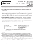
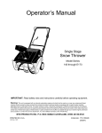
Operators Manual
Model Series
140 thru E173
Single Stage
Snow Throwers
Model 150 shown
IMPORTANT:
READ SAFETY RULES AND INSTRUCTIONS
CAREFULLY
Warning:
This unit is equipped with an inlernal combustion engine and should not be u_ed on or near any unimproved forestcovered, brush-covered or grass-covered land unless the engine's exhaust system is equipped with a spark arraster meeting
applicable local or state laws (if any). if a spark arrester _sused. if should be maintained in eftectlve working order by the operator,
fn the State of California the above is required by taw (Section 4442 of the California Public Resources Code). Other states r_a_ have
similar laws, Federal laws apply on federal lands. A spark attester for the muffler is available through your nearest engine authorized
service dealer or contact the service department. P O. Box 368022 Cleveland, Ohio 44136-9722
MTD
PRODUCTS
PRINTED IN U.S.A.
INC.
P.O. BOX 368022
CLEVELAND,
OHIO 44136-9722
FORM NO. 770-10000
(6/98)
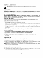
SECTION
1: IMPORTANT
SAFE OPERATION
PRACTICES
WARNING:
THIS SYMBOL POINTS OUT IMPORTANT SAFETY INSTRUCTIONS WHICH, IF NOT
FOLLOWED, COULD ENDANGER THE PERSONAL SAFETY AND/OR PROPERTY OF YOURSELF
AND OTHERS.
READ AND FOLLOW
ALL INSTRUCTIONS
IN THIS MANUAL BEFORE
ATTEMPTING TO OPERATE YOUR SNOW THROWER. FAILURE TO COMPLY WITH THESE
INSTRUCTIONS MAY RESULT IN PERSONAL INJURY. WHEN YOU SEE THIS SYMBOL-HEED ITS
WARNING.
WARNING:
the State of CaliforniaThetoEngine
cause
Exhaust
from defects
this product
contains
chemicals
cancer, birth
or other
reproductive
harm.known
to
DANGER:
Your snow thrower was built to be operated according to the rules for safe operation
in this manual. As with any type of power equipment, carelessness or error on the part of the
operator can result in serious injury. If you violate any of these rules, you may cause serious
injury to yourself or others,
1. TRAINING
•
Read this operator's manual carefully in its entirety
before attempting
to assemble
or operate this
machine. Be completely familiar with the controls and
the proper use of this machine before operating it.
Keep this manual in a safe place for future and
regular reference and for ordering replacement pans.
•
Never allow children under 14 years old to operate a
snow thrower. Children 14 years old and over should
only operate snow thrower under close parental
supervision. Only persons well acquaint_d'with
these
rules of safe operation should be allowed'to Use your
snow thrower.
• No one should operate this unit while intoxicated or
while taking medication th_t'_tr_s
th_ senses or
reactions.
• Use a grounded three wire plug-in for all units with
electricdrivemotorsor electric startingmotors.
• Adjust collector housing height
crushed rock surface.
to clear
Keep the area of operation clear
especially small children'and pets.
•
Exercise caution to avoid slipping'_r'ffalling, e'spe_ially
• Let
engine
and machine
adjust
to
temperature before starting to clear snow.
when operating in re_verse .......
•
....................
_
C
• Thoroughly inspect the area where the equipment is
to be used and remove all door mats, sleds, boards,
wires and other foreign objects.
• Disengage all clutches and shift into neutral before
starting engine.
•
Do not operate equipment without wearing adequate
winter outer garments. Do not wear jewelry, long
scans or other loose clothing which could become
entangled in moving pans. Wear footwear which will
improve footing on slippery surfaces.
gravel
or
• Never attempt to make any adjustments while engine
is running (except where specifically recommended
by manufacturer).
•
1. PREPARATION
.
of all persons
• Before working with gasoline, extinguish all cigarettes
and other sources of ignition. Check the fuel before
starting the engine. Gasoline
is an extremely
flammable fuel. Do not fill the gasoline tank indoors,
while the engine is running, or until engine has been
allowed to cool at least two minutes. Replace
gasoline cap securely and wipe otf any spilled
gasoline before starting the engine as it may cause a
fire or explosion.
outdoor
Always wear safety glasses or eye shields during
operation or while performing an adjustment or repair,
to protect eyes from foreign objects that may be
thrown from the machine in any direction.
2. OPERATION
•
DO not put hands
Keep clear
times.
•
Exercise
crossing
hidden
of
or feet near or under rotating
discharge
extreme
gravel
hazards
caution
drives,
opening
when
and
operating
wafks, or roads.
parts.
auger
at
all
on
or
Stay alert for
or traffic. Do not carry passengers.
• After striking a foreign object, stop the engine,
remove wire from spark plug, and thoroughly inspect
the snow thrower for any damage. Repair the
damage before restarting and operating the snow
thrower.
•
If the snow thrower should start to vibrate abnormally,
stop the engine and check immediately for the cause.
Vibration is generat)y a warnin Oof trouble.
•
Stop engine whenever
you leave the operating
position,
before unclogging
the collector/impeller
housing or discharge guide, and making any repairs,
adjustments, or inspections. Never p{ace your hand in
the discharge or collector openings. Use a stick or
wooden broom handle to unclog the discharge
opening.
Never direct discharge at bystanders or allow anyone
in front of unit.
Disengage
power
to
transporting or not in use.
Never operate the snow thrower without good
visibility or light. Always be sure of your footing and
keep a firm hold on the handles. WalK, never run.
Muffler and engine become
burn• Do not touch.
3. MAINTENANCE
• When cleaning, repairing, or inspecting, make certain
collector/impeller and air moving parts have stopped.
Disconnect spark plug wire and keep away from plug
to prevent accidental starting.
Do not run engine indoors, except when starting
engine and transporting snow thrower in or out of
building• Open doors• Exhaust fumes are dangerous•
•
Do not clear snow across the face of slopes. Exercise
extreme caution when changing direction on slopes.
Do not attempt to clear steep slopes.
•
Never operate snow thrower without guards, plates,
or other safety protection devices in place.
by attempting
hot and can Cause a
AND STORAGE
Check shear bolts, engine mounting bolts, etc., at
frequent intervals for proper tightness to be sure
equipment is in safe working condition.
Never store the machine with fuel in the fuel tank
inside a building where ignition sources are present,
such as hot water and space heaters, clothes dryers,
and the like. Allow engine to cool before storing in
any enclosure.
Always refer to operator's manual instructions for
important details if snow thrower is to be stored for an
extended period.
• Never operate snow thrower near glass enclosure.
automobiles, window wells, drop off, etc., without
proper adjustments of snow thrower discharge angle.
Keep children and pets away.
• Do not overload machine capacity
clear snow at too fast a rate.
when
Use only attachments and accessories approved by
the manufacturer of snow thrower (such as wheel
weights, counter weights, cabs, etc.),
• Take all possible precautions when leaving the unit
unattended.
Disengage the coflectodimpeller,
shift
into neutral, stop the engine, and remove the key.
•
collector/impeller
•
Run machine a few minutes after throwing enow to
prevent freeze up of collector/impeller.
Check clutch controls periodically to verify they
engage and disengage
properly and readjust if
necessary. Refer to operator's manual for adjustment
instructions.
to
• Never operate the machine at high transport speeds
on slippery surfaces. Look behind and use care when
backing.
read, understand
end follow
the warnings and instructions
in this
on the
machine,
WARNING
- YOUR
RESPONSIBILITY:
Restrict the
usemanual
of thisand
power
machine
to persons who
WARNING
DANGER
A
DANGER
Figure
3
1
SECTION
2: FINDING
YOUR MODEL NUMBER
This Operator's Manual is an important part of your new snow thrower, it will help you assemble, prepare and
maintain your snow thrower. Please read and understand what it says.
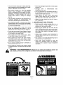
Before you start to prepare your snow thrower for its first use, please locate the model plate and copy the
information from it in this Operators Manual. The information on the model plate is very important if you need help
from your dealer or the MTD customer support department.
• Every snow thrower has a model plate. You can locate it by standing behind the unit in the operating
position and looking down at the dash panel.
• The model plate will look like Figure 2.
This is where
XXX-X-XXX-X-XXX
your model number
will be.
XXXXXXXXXXX
7
This is where your serial number will be.
Copy the model number here:
Copy the sedal number here:
CLEVELAND,
OHIO
44136
Figure 2
SECTION
3:
CALLING
CUSTOMER
SUPPORT
If you are having difficulty assembling this product or if you have any question regarding the controls, operation or
maintenance of this snow thrower, please call the Customer Support Department. You can reach them by calling:
1-800-800-7310
Before you call, make sure that you have both your model and serial number ready. By having the model and
sedal number ready, you help the Customer
Support Representative
give you faster service. To find your'units
model and serial number, see SECTION
2: FINDING YOUR MODEL NUMBER.
SECTION
4: UNPACKING
INSTRUCTIONS
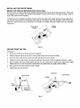
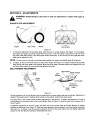
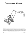
• See Figure 3.
• Remove staples, break glue on the top flaps of the carton or cut tape at carton end and peel along top flap
to open carton. Remove any loose parts included with unit (i.e., Operator's manual, etc.).
• Cut along dotted lines and lay end of carton down flat. Remove packing material.
• Roll unit out of carton. Check carton thoroughly for loose parts.
REMOVE MANUAL & LOOSE PARTS
Figure 3
SECTION 5: SET- UP INSTRUCTIONS
This Operator's Manual covers several models of snow throwers. Much of the Manual pertains to all of the
models. However, there are some areas where only one model is covered. Use only the information that is
appropriate for your model.
ITEMS REQUIRED
FOR SET-UP
• Pair of pliers (not necessary, but helpful)
• 2 cycle oil
• Fresh Gasoline
IMPORTANT:
This unit is shipped WITHOUT GASOLINE or OIL. See separate Engine Operator's Manual
for proper fuel and two cycle engine oil recommendations.
Note:
Reference to right or left hand side of the snow thrower is from the operating position
CONTENTS OF HARDWARE PACK
• (2) Ignition Keys (One may be in the switch on snow thrower)
Models with Optional Extended Chute Crank:
• (1) Eyebolt
• (1) Saddle Washer 5/16" I.D.
• (2) Hex Nuts 5/16-18 Thread
• (1) CotterPin
5
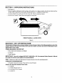
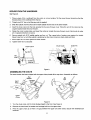
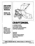
RAISING
THE UPPER
HANDLE
1.
Loosen the hand knob on each side of the handle. Bee Figure 4. Remove packing material (if any).
2.
Squeeze the control handle against the upper handle. Hold it in this position as you raise the handle.
3.
Pull the handle up into the operating position. Be certain not to pinch the cable.
4.
Tighten the hand knobs.
&Pull
1.Loosen Hand
Knobs
4. Tighten
Hand
Knobs
J
2.Squeeze
Control
Handle
Figure 4
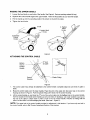
ATTACHING
THE CONTROL
Bottom
Hole In
Control
Handle
\
CABLE
of Cable
Plastic Fitting
Housing
Figure 5
t,
2.
The control cable may already be attached to the control handle, Complete steps two and three if cable is
loose.
Route the control cable over the lower handle. Place the end of the cable into the lower hole in the control
housing as shown in Figure 5. Push the plastic fitting until it locks into the control housing.
3.
Lift the control handle up, and hook the "Z" end of the control cable into the bottom hole in the control handle,
from the outside to the inside (some models use only one hole). If necessary, use a pair of pliers to pull up on
the end of the cable to obtain slack in order to hook it into the control handle. Hold the "Z" fitting with the
pliers, not the cable, to avoid damaging the cable. (See inset - Figure 5.)
NOTE: The upper hole in the control handle provides for adjustment in belt tension.
the control handle, refer to Belt Tension Adjustment
Section of this manual,
6
If you have only one hole in
INSTALLING
(Models
THE
CHUTE
with Optional
CRANK
Extended
Chute Crank only.)
On some units, the chute crank can be installed and secured from the top side of the snow thrower. Other units
are equipped with an adaptor that requires the assembler to tip the unit forward on the auger housing in order to
secure the crank from the underside.
To determine which installation procedure to follow, look at the chute crank coupler located on the top right side of
the instrument panel above the model plate. See Figure 6. If the adaptor has a hole through it visible from the top,
follow the "Secure from the Top" instructions. If the hole is not visible, follow the "Secure from the Underside"
instructions.
\
Figure 6
SECURE
FROM THE TOP.
See Figure 7,
1, Thread one 5/16" hex nut all the way onto the eyebolt,
2.
Slide the eyebolt onto the chute crank. Insert eyebolt into the hole in the lower handle.
3.
Insert the chute crank into the coupler at the top right side of the snow thrower.
4,
Rotate the crank to align holes, and insert the cotter pin. Bend ends of cotter in opposite directions to secure.
5.
Secure eyebolt with 5/16" saddle washer and hex nut. The cupped side of washer goes against the handle.
Adjust lower hex nut until the eyebolt is positioned so the chute crank turns freely. (does not bind)
6.
Move upper hex nut down against the lower handle.
7.
Tighten lower hex nut securely.
Cotter Pin
Chute
\
Crank
Coupler
Rex
Figure 7
7
Chute Crank
SECURE
FROM THE UNDERSIDE.
See Figure 8.
1.
Place a piece of the cardboard from the carton on a level sudace, Tip the snow thrower forward so that the
housing rests on the cardboard from the box.
2.
Thread one 5/16" hex nut all the way onto the eyebolt.
3.
Slide the eyebolt onto the chute crank. Insert eyebolt into the hole in the lower handle.
4.
Insert the chute crank into the hole provided in the snow thrower cover. Place the end of the crank into the
coupler located inside the snow thrower.
5,
Rotate the crank tO align holes, and insert the cotter pin (inside the snow thrower cover). Bend ends of cotter
pin in opposite directions to secure.
6.
Secure eyebolt with 5/16" saddle washer and hex nut. The cupped side of washer goes against the handle
Adjust lower hex nut until the eyebolt is positioned so the chute crank turns freely (does not bind).
7.
Move upper hex nut down against the lower handle.
8.
Tighten lower hex nut securely.
Cotter
Chute Crank
Chute Crank
Pin
/ /
Hex
Figure 8
ASSEMBLING
THE CHUTE
The snow thrower has been shipped with the upper chute pivoted all the way down. Assemble as follows:
Flat
Washer
Hand
Knob___,
No
Gap
. _Carriage
Bolt
/
Upper
Chute
Figure 9
1.
Turn the chute crank until the chute facing straight to the front. See Figure 9.
2.
Remove the hand knob, flat washer and carriage bolt from the upper chute.
3.
Pivot the upper chute up so there is no gap between the upper and lower chute. Secure with hardware just
removed.
FUEL AND OIL MIXTURE
tank
indoors, when
is running
or while
engine that
is still
hot.
Do not
smoke when
filling
WARNING:
Handleengine
gasoline
carefully.
Remember
It Is
highly
flammable.
Never
fill fuel
fuel
tank.
Your snow thrower uses a two cycle engine that requires a mixture of gasoline and two cycle engine oil. Refer to
the Engine Operator's Manual for proper Oil and Fuel Recommendations.
SECTION
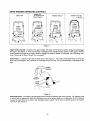
6: CONTROLS
ENGINE OPERATING CONTROLS
The engine operating controls and their functions are as follows (see Figure 10):
Choke Lever - Place choke lever in "ON" position to start a cold engine,
Primer Button - Used to inject fuel directly into the carburetor to insure fast starts in cold weather.
Ignition
Key. Ignition key must be in "ON" position to start engine.
Starter Handle - Used to manually start the engine,
Electric Starter (Optional
Equipment) - Starts engine using a 120V power source
Plug for Electric Start (Optional
and a 120V power source
Equipment)
- Requires use of e two prong outdoor extension cord
8park Plug Cover - Spark Plug located under the cover.
Spark
Plug
Primer
Button
Ignition
Key
Cover_
Electric
Starter
(Optional)
Starter
Handle
Plug for
Electric
Starter
(Optional)
Choke Lever _
0 ff--._,..- On
Figure 10
9
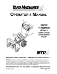
SNOW THROWER
Model 140
OPERATING
CONTROLS
Model 140
(w/ Optional Ext.
Chute Crank)
Models 150,151
AJger
Auger
Control
Handle
1
Control
_'4andle
_. Chute
Models 142,152
172,173
AJger
Control
Handle
_Crank
Chut
T_
E1
Figure 11
Auger Control Handle - Located on the upper handle, the auger control handle is used to engage and disengage
the augers. See Figure 11. The snow thrower is designed to be propelled by the rotation of the augers. Pull the
control handle back against the upper handle to engage the augers; release to disengage. See "Operating Tips"
under "Operating the Snow Thrower" for more detail.
Chute Crank - Located on right side of dash panel, See Figure 11. The Chute Crank determines the direction
snow will be discharged. Turn clockwise to discharge snow to the left. Turn counterclockwise to discharge to the
right,
Distance
_
Greater
Less
Distance
Hand
Knob
Figure
12
Discharge
Chute - The angle of the discharge chute controls the distance the snow is thrown. The distance snow
is thrown can be adjusted by tilting the discharge chute up for greater distance, or tilting down for less distance.
Loosen the hand knob on the side of the discharge chute to adjust, Tilt the chute to desired position, and tighten
hand knob. See Figure 12.
10
SECTION
7:
OPERATION
Warning' Observe all warning labels on the snow thrower prior to use. See Section 1.
FUEL MIXTURE
Important:
Mix oil with gasoline as instructed in the Oil and Fuel Recommendations Section in the separate
Engine Operator's Manual packed with your snow thrower. Read and follow all instructions carefully.
BEFORE
STARTING
ENGINE
Read the Engine Operator's Manual carefully in its entirety before attempting to operate the machine. _e
completely familiar with the controls and the proper use of the engine before operating the unit. Keep both
Operator's Manuals in a sate place for future and regular use.
STARTING
THE ENGINE
To start the engine on your snow thrower, follow the Starting Instructions in the Engine Operator's Manual.
OPERATING
THE SNOW THROWER
1.
Start the engine as instructed in the Engine Operator's Manual.
2.
Adjust the discharge chute up or down as desired. Then use the chute crank to position the discharge to
discharge snow with the wind. Do not throw snow toward a building as hidden objects could be discharged
with enough force to cause damage.
3.
Making certain no bystanders or obstacles are in front of the unit, engage the auger control handle. As the
snow thrower starts to move. maintain a firm hold on the handle, and guide the snow thrower along the path
to be cleared.
4.
Release the auger control handle to stop the snow throwing action and forward motion.
TO STOP THE ENGINE
1.
Run the engine for a few minutes before stopping to help dry any moisture on the engine.
2.
To stop engine: Turn ignition key to OFF position and remove it from the snow thrower.
NOTE:
3.
Do not lose ignition key. Keep it in a safe place. Engine will not start without the ignition key.
Wipe all snow and moisture from the unit. Move the choke lever back and forth several times and leave in the
ON position.
OPERATING
TIPS
1.
For most efficient snow removal, remove snow immediately after it falls.
2.
Discharge snow downwind whenever possible. Slightly overlap each previous cleared path.
3.
Lifting up on the handle will allow the rubber on the augers to propel the snow thrower forward.
downward on the handle will raise the augers off the ground and stop the forward motion.
Pushing
NOTE; Excessive upward pressure on the handle will result in premature wear on the rubber auger blades
which would not be covered by warranty.
4.
Run the engine
for a few minutes
before
stopping to help dry any moisture on the engine.
5.
Clean the snow thrower thoroughly
6.
It is not recommended
that you operate this snow thrower on gravel as loose gravel can be easily picked up
and thrown by the auger, causing an injury or damage to the snow thrower.
after each use.
11
SECTION
8:
ADJUSTMENTS
running,
WARNING:
SHAVE
NEVER attempt to clean chute or make any adjustments
or repairs while engine is
PLATE ADJUSTMENT
I,
/
Augers
Shave Plate
Wheels
Nuts & Bolts
Figure 13
t.
To check the adjustment of the shave plate, place the unit on a level surface. See Figure 13. The wheels,
shave plate and augers should all contact the level surface. It the shave plate is adjusted too high, the snow
may blow under the housing. If the shave plate wears excessively, or the unit will not self propel the shave
plate may be adjusted too low.
NOTE:
2.
On new units or units with a new shave plate installed, the augers may slightly raise off the ground.
To adjust, tip the snow thrower back so it rests on the handle. See Figure 13. Loosen the lock nuts and bolts
which secure the shave plate to the housing, Move the shave plate to desired position and retighten the nuts
and belts. Make certain all nuts and bolts are tightened securely.
BELT TENSION
ADJUSTMENT
High Pos t on Middle Position
X
Upper
Hole
Idler
Bracket
Clutch
Cable
• Low Position
Spring on
End of Clutch
Cable
Jger
Pulley
Housing
Figure
Periodic
adjustment
of the belt tension may be required
needed
if the augers seem
to hesitate
14
due to normal
while turning, but the engine
stretch and wear on the belt. Adjustment
is
maintains the same speed.
The upper hole in the control handle provides adjustment for belt tension. To adjust, disconnect the "Z" end of
control cable from the bottom hole in the control handle. Refer to Figure 14. Hook the cable into the upper hole in
control handle.
If additional adjustment is required, adjust the other end of the control cable at the Idler Bracket as follows:
Remove the belt cover. See Figure 15. There are three adjustment holes provided in the Idler Bracket Assembly.
See Figure 14. To adjust, move the extension spring on the end of the clutch cable to the next higher adjustment
position on the Idler Bracket Assembly. Reassemble belt cover.
12
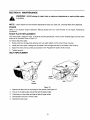
SECTION
9:
MAINTENANCE
is running,
WARNING:
NEVER attempt to clean chute or make any adjustments or repairs while engine
NOTE: Check engine and snow thrower frequently for loose nuts, bolts, etc., and keep these items tightened,
ENGINE
Refer to the separate Engine Operator's
procedures.
SHAVE
PLATE
Manual packed with your snow thrower for all engine maintenance
REPLACEMENT
The shave plate is subject to wear. It should be checked periodically. There are two wearing edges and the shave
plate can be reversed. Refer to Figure 13.
To remove the shave plate:
1.
Remove the four cardage bolts and hex lock nuts which attach it to the snow thrower housing.
2.
Install new shave plate, making sure the heads of the carriage bolts are on the inside of the housing.
3.
Adjust the shave plate according to procedure in the "Adjustment" section of this manual.
4.
Tighten securely.
BELT REPLACEMENT
13eit
Hex
Screws
Figure 15
1.
Remove the belt cover by removing five hex screws. See Figure 15.
2.
Pull up on the idler pulley and slip the belt off engine pulley.
3.
Push down on idler pulley and slip the belt off auger pulley.
4.
Reassemble new belt in reverse order.
5.
Reinstall the belt cover.
13
SECTION
10: OFF-SEASON
WARNING:
STORAGE
Never store engine with fuel in tank indoors or in enclosed,
poorly ventilated
areas
fumes
may reach
an open flame, spark or pilot light as on a furnace, water
heater, where
clothesfuel
dryer,
or other
gas appliance.
• Clean snow thrower thoroughly.
• Follow "Storage" instructions found in the separate Engine Operator's
storage properly is important to prevent problems next season.
Manual. Preparing the engine for
• Store in a clean, dry area. Block the snow thrower up so it is not resting on the rubber auger blades.
NOTE: When storing any type of power equipment in an poorly ventilated or metal storage shed, care should be
taken to rustproof the equipment, especially springs, cables and all moving parts.
SECTION
11: TROUBLE
SHOOTING
GUIDE
!
Trouble
Possible
Engine_ils
to start
Cause(s)
iFuel tank empty, or stale fuel
iBlocked fuel line.
iKey not in switch on engine,
Spark plug wire disconnected.
Faulty spark plug.
Improper gasoline and oil mixture. __
lUnit_ing
on_CHOKEL -!Blocked fuel line or stale fuel.
Water or dirt in fuel system.
Engine runs erratic
Engine overheats
_Refer
Move
Clean
Drain
iRefer
to rue m xture n separate eng ne manua.
choke lever to OFF position.
fuel line: fill tank with clean, fresh gasoline/oil.
fuel tank. RefiU with clean, fresh gasoline/oil.
to engine manual packed with your unit
Incorrect fuel mixture.
Drain fuel tank. Refill with proper fuel mixture. Refer to
engine manual packed with your unit.
IRefer to engine manual packed with your unit or have
Icarburetor adjusted by an authorized service dealer.
Vent in gas cap plugged.
L ohaUsLpo
plugged:
Excessive vibration
f
se parts or damaged auger.
:rincorrect adjustment of drive cable
IDdve belt loose or damaged.
--
IFill tank with clean, fresh gasoline!oil mixture, Refer to
engine manual packed with your unit.
Clean fuel line
Insert Key
Connect wire to spark plug.
Clean, adjust gap or replace.
IRefer to engine manual packed with your unit or have
carburetor adjusted by an authorized service dealer
-Sp-arkpi_ose.
Unit fails to propel itself.
Action
iCarburetor out of adjustment.
Carburetor not adjusted properly.
Loss of power
Corrective
Connect and tighten spark plug wire.
Clear vent.
Clean-see maintenance section.
St0pengine_ely
and-_sconnect spark plug
w re T ghten a I bo ts and nuts. Make all necessary
repairs. If vibration continues, have unit serviced by an
authorized service dealer.
Adjust drive cable. Refer to Adiustment section of this
manua.
' Replace drive belt. Refer To Belt Replacement in
Maintenance section of this manual.
I
Unit fails to discharge snow.
Discharge chute clogged.
JForeign obiect lodged in auger.
!Incorrect adjustment of drive cable.
i Drive belt loose or damage.
Stop engine immediafely and disconnect spark plug
iwire. Clean discharge chute and inside of auger housing
i Stop engine immediately and disconnect spark plug
wire. Remove object from auger.
Adjust drive cable. Refer to Belt Tension Adjustment in
Adjustment section of this manual.
Replace drive belt. Refer to Belt Replacement in
Ma ntenance sect on of ths manual.
Refer to separate engine manual packed with your mower for more engine related information.
NOTE: For repairs beyond lhe minor adjustments listed above, contact your nearest authorized service dealer or
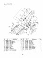
call 1-800-800-7310 for the Customer Support Center.
14
Models
140
150
E150
E151
REF.
NO.
1
2
3
4
PART
NO.
710-1270
710-0487
712-0324
720-0276
5
6
7
8
9
725-0157
_746-0883
1747-0946
i749-0705
1736-0451
DESCRIPTION
:Screw--Ova! C-Sink L
Bolt Carriage
NUt Insl. Lock
Knob--Handle
Tie Cable
Body--Lever Control
Handle Ass'y. Control
Handle--Upper
Washer Saddle
i QTY.
_:-1
t 2
1
2
1
1
1
1
2
Models
142
E 152
E172
E173
RER
NO.
-' I
2
3
i
!
4
5
6
7
8
9
10
PART
NO.
7i0:1270
710-0487
712-0324
DESCRIPTION
Screw--Oval C-Sink L
Bolt----Carriage
Nut Insul. Lock
720-0295
720-0264
1725-0157
736-0451
746-0883
747-0956
749-0711A
Grip Foam
Knob Handle
Tie Cable
Washer Saddle
Body--Lever Control
Handle Ass'y. Control
IHandle--Upper
OTy_
1
1
2
1
2
1
1
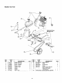
t5
Models
140 thru E173
/
/
Cable Spring in
16
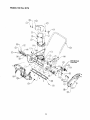
Models 140 thru E173
T
NO.
1
2
3
4
5
PART
NO.
710-0167
,710-0276
1710-0323
j710-0481
1710-0642
6
7
8
9
10
11
12
13
15
16
17
1710-1005
[710-0773
710-0896
710-3015
711-0848A
712-0429
712-3010
712-0116
712-3027
720-0284
731-0851A
18
19
20
21
22
23
731-0915B
731-0921
731-1033
732-0357A
736-0108
736-0119
_DESCRIPTION
; Bolt--Carriage
Bo[t_arriage
;Screw--Pan
Head
i
-4
1
1
1
1
6
2
4
6
1
1
3
1
10
1
3
1
1
1
1
2
Bolt--Carriage
Screw--Hex Washer
!Screw--Hex Washer
IScrew--Hex
:Screw--Hex
Serew--Hex
.Axle
Washer
Washer
Cap
i Nut--Hex Center Lock
,Nut--Hex
Nut--Hex Lock
Nut--Hex Lock Flanged
Knob
Keeper-4_hute
Chute-.--Lower
Chute--Upper
Shave P ate
ISpring--Extension
!Washer--Flat
Washer--Lock
t°OF
t
NO.
NO.
1
PART
734-1176
-REF_.
NO._,
PART
NO.
36°
26
27
28
30
31
32
,736-0159
736-0326
,736-0329
741-0600
746-0910A
i748-0234
33
34
35
!749-0796
756-0313
,784-5174
36
37
784-5176
784-5175B
t
40
41
42
1763-0613
710-0352
1,784-5720
43
44
45
46
710-0451
736-0242
741-0475
710-0459A
Wheel Ass'y,
17
DESCRIPTION
Q
Washer
Washer--F at
Washer--Lock
Ball Bearing
ICable--Clutch
!Spacer--Shoulder
i Handle---Lower
IIdler--Flat
Cup-Bearing
Cover--Belt
i Bracket--Idler/Brake
Housing--Blower
[Auger Ass'y, Comp.
39
DESCRIPTION
.=
i
_ash_t-
IAuger Rubber Replacement
Screw--Hex Washer
Bracket - Crank
=Screw - Cap
Washer - Bell
!Bushing
IScrew - Cap
i
2
1
1
2
1
1
1
1
2
1
1
1
1
1
1
1
2
2
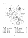
1
1
r
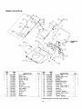
Models
140 and E142
/
/
Engine
\
\
\
C)
®
RE_
NO.
1
2
3
4
5
6
7
8
9
10
11
12
i
13
i
14
_5
PART
NO
-684-0056
710-0805
710-0895
710-1268
712-0252
712-3010
714-0104
715-0138
720-0201A
725-0201
725-1425
726-0100
731-0702
731-1133A
hEF. [
!
736-0119
I
DESCRIPTION
NO.
P-_
I
NO
16_36-_
Screw--Rex
Screw--Hex Tap
!Screw--Hex Tap
Nut Hex
Nut--Hex
;Pin-Cotter
iPin Roll
Knob---Chute Crank
Key--Ignition
Switch--Key
Nut Push
Shroud
!Plug
!Washer Lock
4
2
9
1
4
1
1
1
2
1
1
1
1
4
_
17
18
20
21
22
23
24
26
27
28
29
30
31
32
736-0225
[736-0400
,,741-0475
784-5178A
784-5344
714-0tll
747-0737
684-0126
750-0785
715-0138
735-0234
1747-0697
_712-3010
i738-0451
t Optional
18
Model
i
DESCRIPTION
lWasher- Fiat
rWasherInternal
-Lock
Washer Flat
Bushing
Bracket Chute Crank
l Crank Ass'y. Chute
4Cotter Pin T
Crank - Chute - Upper ?
Crank - Chute - Lower ?
Spacer 1"
Pin - Roll t
Grommet - Rubber t
Eyebolt - Chute Crank ?
Nut - Hex "l
Washer- Saddle t
140 Chute
Crank Assembly
I
1
1
1
1
1
1
1
1
1
1
2
1
Models
150, E150, E173
1/
RER _
PART
NO.
NO
1
710-0805
2
_710-1005
3
4
5
6
7
8
9
10
11
12
13
710-1003
710-1268
'712-0252
712-3010
714-0104
714-0507
715-0138
720-0201A
725-0201
725-1425
726-0100
•
DESCRIPTION
Scre_v-Hex
....
Screw-Hex Washer
Screw-Hex
Serew-Hex
Nut-Jam
PNut-Hex
Hairpin
Pin-Cotter
Pin Roll
Knob
Key-Ignition
Sw tch
_Cap-Push
Shroud-Black
14 173!-1087
QTY.
4
1
1
12
1
6
1
1
2
1
2
1
1
1
REF. 73 PART
NO.
15
16
731-1133A
17
735-0234
18
736-0119
19 •736-0185
2O
736-0225
21
736-O4OO
22
736-0451
24
747-0697
25
747-0737
26
750-0785
27
,684-0126
28
'784-5572
DESCRIPTION
Cover-Choke
Plug-Insert
Grommet-Rubber
Washer*Lock
Washer-Flat
Washer-Lock-Internal
Washer-Flat
Washer-Saddle
Eyebolt-Chute Crank
Crank-Chute-Lower
Spacer
Crank-Chute-Upper
,Dash
I
2
19
1
1
4
2
1
3
1
1
1
1
1
1
!
[
J
I
Models
E151, E172,
Shtpp_KI
REF, -
PART
NO.i
NO
1
784-5572
_-
IJDash
QTY.
REF.
NO.
DESCRIPTION
2
3
4
710-0805
710-1005
7"10-1003
IScrew--Hex Cap
Screw--Hex Washer
Screw---Hex
5
6
7
710-1268
712-3010
714-0104
iScrew--Hex
Nut--Hex
Hairpin
8
9
10
11
12
13
14
714-0507
715-0138
720-0201A
725-0201
725-1341B
725-1346
_725__'!347
Pin--Cotter
Pin--Roll
Knob
Key--Ignition
Key--Ignition with Logo
Nut--lgn t on Switch
!Cover--Ignition
Switch
r
.._
1
2
1
1
1
1
1
2O
PART
NO
15
16
17
18
10
20
21
725-t425
726-0100
731-1089A
731-1133A
731-!765
735-0234
736-0119
23
24
26
27
28
29
736-0225
736-0451
747-0697
747-0737
750-0785
684-0126
DESCRIPTION
Switch--Key
Cap--Push
Cover_Choke
Plug-- nsert
Shroud--Black
Grommet--Rubber
Washer--Lock
_Washer--Lock
Internal
IWasher--_addle
Eyebolt_hute
Crank
Crank--Chute Upper
Spacer
Crank-_Chute Lower
r
. QTY.
1
1
1
1
1
1
4
1
1
1
1
1
1
Models
140, E142
I
I
Tightening Torque:
150-130 in. Ibs.
"-FIEF.
NO.
1
2
i
i
PART
NO
7i0-0157
710-0805
i
_
DESCRIPTION
--| Screw--Hex Cap
/Screw--Hex Cap
3
4
5
!710-0896
1726-0205
!736-0242
IScrew--Washer
jClamp--Hose
Washer--Bell
6
7
8
750-0589
750-0716
_751-0352
Spacer
Spacer
iTank--Fuel
QTY.
1
4
2
2
5
4
1
1
-'_
-_- PART
NO. I
NO
9
751-0535-12
10
754-0367
11
756-0416B
12
756-0550
13
1784-5177
14
-N/I
21
DESCRIPTION
Hose--Fuel 12"
V-Belt
V-Pulley Half
Pulley
Engine Support Bracket
Obtain from Engine
Manufacturer
iOEM-390-6_Electric
Start Kit (Optional)
QTY.
Mode1150
Tightening Torque;
lS0-300 in. Ibs.
REF.T
NO.
1
2
4
5
6
7
8
9
10
PART
NO.
705-5139
710-0157
710-0289
710-0896
710-30Z5
726-0205
738-0119
736-0242
:736-0320
DESCRIPTION
Bracket - Supped Gas Tank
Screw - Hex Cap
Screw - Hex
Screw - Washer
rScrew - Hex Cap
!Clamp - Hose
;Washer - Lock
Washer - Bell
iWasher- Lock
NO.
11
12
13
14
15
16
17
19
N/I
i
1
2
2
4
2
4
1
2
22
NO.
741-0475
751-0535-16
751-0540A
"QTY. i
!
DESCRIPTION
Bushing - PJastic
Hose- Fuel Line 16"
Tank- Fuel 2 Qt.
.....
1-_
1 J
1 I
L
78t-0800
Cap - Fuel
1754-0101A
V-Belt
756-0416B
V-Pulley Half
756-0475
Pulley
-Obtain from Engine Manufacturer
!OEM-3g0-gg61Elect_-ic Start.Kit (Optional)
_
1
1
2
1
1
._ 1
Models
E150, E151, E152, E172, E173
Tightening Torque:
150-300 in. Ibs.
@
REF.
NO.
--t
PART
NO
629:0z36
2
3
5
6
7
8
9
10
..11
705-5139
710-0157
710-0289
710-0896
710-1003
710-3025
726-0152
726-0205
i:736"0119
i
DESCRIPTION
Cord - Extension 110V3M
2 Prong
Bracket - Support Fuel Tank
iScrew - Hex Cap
' Screw - Hex
!Screw - Washer
IScrew - Hex
Screw - Hex Cap
'Clamp - Moun ing
iClamp - Hose
IWasher - Lock
I REE
12
13
14
15
16
17
18
19
20
22
1
1
1
2
2
2
4
1
2
4
_oTv.i .o.
I
PART
736-0242
736-0329
741-0475
751-0535-16
751-0540A
751-0800
754-0101A
756-0416B
756-0475
--
NO
DESCRIPTION
Washer - Bell
Washer- Lock
Bushing - Plastic
Hose - Fuel Line 16"
Tank - Fuel 2 QI.
Cap - Fuel - Black Letters
V-Belt
V-Pulley Half
Pulley
i Obtain from Engine Manufacturer
23
QTY.
1
2
MANUFACTURER'S
LIMITED
WARRANTY
FOR:
YA..c,,N s)[(
For TWO YEARS from the date of retail purchase
within the United States of America, its possessions
and territories, MTD PRODUCTS INC will, at its
option, repair or replace, for the original purchaser,
free of charge, any part or parts found to be
defective in material or workmanship. This warranty
covers units which have been operated
and
maintained
in accordance
with the operating
instructions furnished with the unit, and which have
not been subject to misuse, abuse, commercial use,
neglect,
accident,
improper maintenance
or
alteration.
products sold or exported outside of the United
States of America, its possessions and territories,
except those solcl through MTD PRODUCTS INC's
authorized channels of export distribution.
Normal wear parts or components
thereof are
subject to separate terms as noted below in the "No
Fault Ninety Day Consumer Warranty" clause.
3.
Log splitter pumps, valves and cylinders or
component parts thereof are covered by a one
year warranty.
All normal wear part failures will be covered on this
product for a period of go days regardless of cause.
After 90 days, but within the two year period, normal
wear parts failures will be covered ONLY IF caused
by defects in material or workmanship of OTHER
component parts. Normal wear parts are defined as
batteries*, belts, blades, blade adapters, grass bags,
rider deck wheels, seats, snow thrower skid shoes,
shave plates and tires.
4.
All other warranties,
express
or implied,
including any implied warranty of merchantability
or fitness for a particular purpose, are hereby
expressly disclaimed in their entirety.
5.
The provisions as set forth in this warranty
provide the sole and exclusive remedy of MTD
PRODUCTS INC's obligations arising from the
sales of its products. MTD PRODUCTS INC will
not be liable for incidental or consequential loss
How to obtain servioe:
Warranty service is
available, with proof of pumhasa, through your local
authorized service dealer. To locate the dealer in
your area, please check the yellow pages or contact
the
Customer
Service
Department
of MTD
PRODUCTS INC, P. O. Box 368022, Cleveland,
Ohio 44136-9722. Phone 1 (800) 800-7310. The
return of a complete unit will not be accepted by the
factory unless prior written permission has been
extended by the Customer Service Department of
MTDPRODUCTSINC.
Transportation
charges: Transportation
charges
for the movement of any power equipment unit or
attachment are the responsibility of the purchaser.
Units exported out of the United States: MTD
PRODUCTS INC does not extend any warranty for
Other Warranties:
1.
2,
The engine or component parts thereof carry
separate warranties from their manufacturers.
Please refer to the applicable manufacturer's
warranty on these items.
*Batteries are covered by a 90-day replacement
warranty.
or damage.
How state law relates to this warranty: This
limited warranty gives you specific legal rights, and
you may also have other rights which vary from state
to state. Certain disclaimers are not allowed in some
states and therefore they may not apply to you
under a_l circumstances.
NOTE: This warranty does not cover routine
maintenance items such as lubricants, filters, blade
sharpening and tuneoups, or adjustments such as
brake adjustments,
clutch adjustments
or deck
adjustments. Nor does this warranty cover normal
deterioration of the exterior finish due to use or
exposure.