1
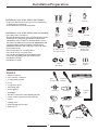
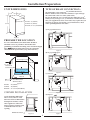
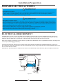
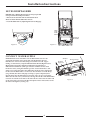
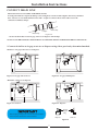
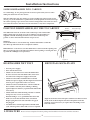
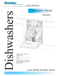
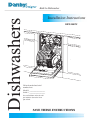
Dishwashers
Built-In Dishwasher
Installation Instructions
DDW1802W
Write the model and serial
numbers here:
Model # __________________
Serial # __________________
You can find them on the tub wall
just inside the door or
. the lower
part of back.
SAVE THESE INSTRUCTIONS
BEFORE INSTALLATION
Read these instructions completely and carefully.
WARNING
Electric Shock Hazard
Disconnect electrical power at the fuse box or circuit breaker
box before beginning installation. Failure to follow this
warning could result in serious injury or death.
CONTENTS
Material You Will Need . . . . . . . . . . . . . . . . . . . . . . . . . . . . . 1
Tools
. . . . . . . . . . . . .. . . . . .. . . . . . . . . . . . . . . . . . . . . . . . . . . 1
Unit Dimensions . . . . . . . .. . . . . . . . . . . . . . . . . . . . . . . . . . . 2
Prepare the Location
. . . .. . . . . . . . . . . . . . . . . . . . . . . . . . . 2
Corner Installation . . .. . . .. . . . . . . . . . . . . . . . . . . . . . . . . . . 2
Note to Installer
Be sure to leave Installation Instructions and User
Instructions with owner.
Note to Consumer
Keep these instructions with your Owners Manual for
future reference.
Skill level
Installation of this dishwasher requires basic mechanical
and electrical skills. Improper installation can result in
product failure which is not covered under the
Product Warranty.
Drain Connections ............ . . . .. . . .. . . . . . . . . . . . . . . . . . . 2
Prepare Electrical Wiring . .. . . .. . . .. . . . . . . . . . . . . . . . . . . 3
Electrical Requirement . . . . . . . . . . . . . . . . . . . . . . . . . . . . . . 3
Prepare Water Line
. . . .. . . . . . . . .. . . . . . . . . . . . . . . . . . . . 4
Adjust Door Balance . . . .. . . . . . . . . .. . . . . . . . . . . . . . . . . . . 4
Remove Kick-Plate . .. . . .. . . . . . . . . . . . . . . . . . . . . . . . . . . . 4
Install Power Cord
. . . .. . . .. . . . . . . . . . . . . . . . . . . . . . . . . 5
Position Water Line and House Wiring. . . . . . . . . . . . . . . . 5
Insert Drain Hose through Cabinet
. . . .. . . .. . . . . . . . . . . . . . . . . . . 5
and Connect Water Line
Slide Dishwasher into Cabinet . . . .. . . . . . . . . . . . . . . . . . . 5
IMPORTANT
The dishwasher must be installed so as to allow for future
removal from the enclosure in the event service is required.
Level Dishwasher, Secure to Cabinet . . . . . . . . . . . . . . . . . 6
Connect Drain Hose . . . . . . . . . . . . .. . . . . . . . . . . . . . . . . . . 7
Connect Power Supply
Pre-Test Check List
. . . .. . . . . .. . . . . . . . . . . . . . . . . . . 8
. . . .. . . . . . . . . . . . . . . . . . . . . . . . . . . . 8
Before You Begin– Examine the dishwasher carefully,
Dishwasher Wet Test
if the product is damaged, you should immediately
contact one of the following:
Replace Kick-Plate . . .. . . .. . . . . . . . . . . . . . . . . . . . . . . . . . . 9
• Danby Product Ltd. Customer Service Department
@ 1-800-26-DANBY
• Danby authorized service depot. (see authorized
service depot listing enclosed with product)
WARNING
Tip Over Hazard
Do not use dishwasher until completely installed.
Do not push down on open door.
Failure to follow this warning can result in serious injury.
Literature
. . . .. . . .. . . . . . . . . . . . . . . . . . . . . . 9
. . . .. . . .. . . . . . . . . . . . . . . . . . . . . . . . . . . . . . . . 9
Installation Preparation
MATERIALS YOU WILL NEED (INCLUDED)
• 2 #8 x 5/8” flat head wood screws to secure dishwasher
to underside of countertop.
• Strain Relief for electrical connections.
Waste Tee
Wood Screws
MATERIALS YOU WILL NEED (NOT INCLUDED)
Air Gap
Hand
Shut-off
Valve
• 3/8” Male (N.P.T.) 90º Elbow.
• Flexible Braid Hot Water Line (Use Engineered Polymer
Braid type hose designed specifically for dishwasher
installations only, available at most Hardware Stores)
DO NOT USE REGULAR (TYPE) RUBBER HOSE OR
GARDEN HOSE FOR INCOMING WATER LINE.
• Hand Shut-off Valve (5/8” O.D. tube x 3/8” O.D. tube)
• Seal (Teflon) Tape
• Electrical Cable (12 ~ 14 Gauge Wire)
• Wire Nuts (for 12 ~ 14 gauge wire)
• Air Gap Kit (depending on drain method used)
• Waste Tee (depending on drain method used)
• Drain Hose Clamps
• Drain Hose Coupler
Thread
Seal Tape
Wire Nuts
Electrical Cable
90° Elbow, Ferrule
and Compression nut
Drain
Hose Clamps
Dishwasher Approved
Flexible Braid
Hot Water Line
Drain Hose
Coupler
Strain Relief
TOOLS
•
•
Head screwdriver
5/16 " and 1/4 " nutdriver
•
•
6" Adjustable wrench
•
Carpenters square
•
Measuring tape
•
Safety glasses
•
Flashlight
•
Bucket to catch water when flushing the line
•
15/16" socket (optional for skid removal)
•
•
Gloves
•
Drill and approprivate bits
•
Hole saw set
Head
Screwdriver
1/4" and 5/16"
Nutdriver
Level
Level
Hole Saw Set
Flashlight
Carpenters
Square
Tubing Cutter
Safety Glasses
Tubing cutter
Gloves
6" Adjustable
Wrench
Measuring Tape
Drill and Bits
1
Installation Preparation
UNIT DIMENSIONS
18"
TYPE OF DRAIN CONNECTION:
The dishwasher comes with a factory installed drain hose.
Drill 2” diameter hole to allow the drain hose to pass through
the cabinet and connect to drain. (under sink)
Review the different ways of connecting the dishwasher to the
drain system, (See Figs 4, 5, 6, 7) and choose a method that best
suits your (application) needs. Local codes may require that you
install an air gap kit (not include) on your dishwasher, check
with a qualified plumber if in doubt.
23"
DEPTH: 23"(580mm)
33"~35"
WIDTH: 18"(450mm)
HEIGHT: 33"~35" (840~890mm)
A) air gap with waste tee
Figure 1
PREPARE THE LOCATION
For ease of installation, the dishwasher should be
installed as close as possible to the kitchen sink
(plumbing) to facilitate incoming water and drain supply
lines. Note: Built-in dishwashers must be completely
enclosed on all exposed sides; (top, sides and rear)
Figure 4
B) air gap with disposer
Area of Pipe or wires
Min. 24"
33 " - 35 1/2 "
Underside of
Countertop to Floor
Area of Plumbing and
Electric Service
Figure 5
C) waste tee
6"
Min. 18"
Floor must be Even
With Room Floor
Figure 2
DEPTH:
18"
24"(610mm)
WIDTH:
18 " (460mm)
HEIGHT:
33"~35-1/2"(840~900mm)
Min.
CORNER INSTALLATION
Figure 6
D) disposer
If you install the dishwasher
into a corner, allow 2" min.
Clearance between dishwasher
and adjacent cabinet, wall or
other appliances. Allow 22"
min. Clearance from the front
of the dishwasher for door
opening.
Minimum Clearance 2"
18"
Min.
22"
Figure 3
Figure 7
2
Installation Preparation
PREPARE ELECTRICAL WIRING
WARNING!
FOR PERSONAL SAFETY:
Disconnect electrical power at the fuse box or circuit breaker before beginning installation. Do not use extension cords
or (plug) adapters with this appliance. Such can result in fire, electrical shock or other personal injury. Failure to
follow these instructions could result in serious injury or death.
WARNING!
GROUNDING INSTRUCTIONS:
The dishwasher must be connected to a grounded metal, permanent wiring system. The equipment-grounding conductor
must be run with the circuit conductors and connected to the appliance’s equipment grounding terminal or lead. It is the
customer’s responsibility to contact a qualified installer (or electrician) to make sure the electrical installation conforms
with the National Electrical Code and local codes and ordinances.
Do not connect the dishwasher to the power supply until the appliance is permanently grounded.
All wiring connections must be properly enclosed inside the electrical junction box.
Failure to follow these instructions could result in serious injury or death.
ELECTRICAL REQUIREMENT
This dishwasher operates on a 120 volt, 60 Hz electrical supply. You must provide a separate (individual) circuit with a fuse or
circuit breaker rated for at least 15 amps, but not more than 20 amps. Your dishwasher circuit should not be used for any other
appliance while the dishwasher is operational, as the dishwasher will require the full capacity of the circuit.
If the electric supply provided does not meet the above specifications, immediately contact a qualified electrician to investigate and
correct any electrical supply problem(s).
The electrical connection (junction box) is located on the right front side of the dishwasher behind the kick-plate. (See Fig. 11)
For cable direct (hard wire) connections, route the electrical cable as shown. (Fig. 8) The cable must extend a minimum of 24” from
the rear wall to the front cabinet.
IMPORTANT: THE ELECTRICAL POWER LINE MUST NOT SHARE THE SAME OPENING (HOLE) AS THE WATER LINE.
1-1/2" Dia. Hole (Max.)
3"
from
Cabinet
24"
from Wall
Ground
Black
Figure 8
3
White
Installation Instructions
Kick-Plate
Screws
REMOVE KICK-PLATE
Figure 11
Before you can make the water/electrical connections to the dishwasher,
the "kick-plate" must first be removed.
To remove the kick-plate, lay the dishwasher on it's back. Remove 4
screws (2 on each side) from the underside of the kick-plate. (See Fig.11)
It is not necessary to reinstall these screws once removed, as the
kick-plate simply snaps into position when reinstalled.
To remove kick-plate, insert fingers under one side and pull upward,
this may require applying some force (pressure) before the kick-plate
releases. Repeat the same procedure on the opposite side.
PREPARE WATER LINE
Kick-Plate
Water Inlet
Valve
Electrical
Connection Box
ADJUST DOOR BALANCE
The water line should enter from the left side of the cabinet.
(See Fig. 9) Drill 1-1/2” diameter hole to allow water line to
pass through the cabinet. Drill a secondary 1/2” diameter hole
to allow the electrical power line to pass through the cabinet.
The balance of the door is set for moderate opening/closing tension.
If you feel it is not adjusted to your satisfaction, it can be adjusted
by increasing/decreasing the tension of the door springs. (See Fig. 10)
IMPORTANT: THE WATER LINE AND ELECTRICAL
LINE SHOULD NOT SHARE THE SAME HOLE/OPENING.
Remove the spring holding pin and reposition to higher/lower hole
opening.
The dishwasher must be installed on the “hot” water line, using
no less than 3/8” O.D. copper tubing, or alternatively 3/8”
flexible braid (high pressure, high temperature) hose
engineered/designed specifically for dishwasher installations.
(this type of hose is available at most local hardware stores)
The higher hole openings will increase door tension.
The lower hole openings will decrease door tension.
It is also recommended to install a shut-off valve in an accessible
location (i.e. under the sink) between the incoming hot water
supply and the dishwasher connection.
WARNING: Always exercise extreme caution when making
adjustments to the door and door springs and make sure the door is
fully closed before attempting any such adjustments.
The dishwasher water “inlet valve” is located at the lower front
center of the dishwasher behind the kick-plate. (See Fig. 11)
Incoming water temperature should be at least 120ºF (49ºC) and
the water pressure should be between 20~120 psi.
Increase
Spring
Tension
Decrease
Spring
Tension
4"
1-1/2" Dia. 5"
Shut-off Hole
Hot
5"
4"
Valve
2"
From
Cabinet
6"
19" From Wall
Figure 10
2" From Floor
Cabinet Face
Figure 9
4
Installation Instructions
PREPARE DRAIN CONNECTION:
The dishwasher comes with a factory installed drain hose.
Drill 2” diameter hole to allow the drain hose to pass through the
cabinet and connect to drain. (under sink)
Review the different ways of connecting the dishwasher to the
drain system, (See Fig’s 4, 5, 6, 7) and choose a method that best
suits your (application) needs.
Local codes may require that you to install an air gap kit (not include)
on your dishwasher, check with a qualified plumber if in doubt.
Figure 14
5
Installation Instructions
LEVEL DISHWASHER
IMPORTANT-- Dishwasher must be level for proper dish
rack operation and wash performance.
* Place level on door and rack track inside the tub as
shown to check that the dishwasher is level.
* Level the dishwasher by adjusting the four leveling legs.
Check
Level
Front
to Back
Check Level
Side To Side
Turn Legs
to Adjust
Figure 15
Figure 16
CONNECT WATER SUPPLY
IMPORTANT: Check and make sure the dishwasher does not rub
against the incoming water supply line. The dishwasher must be
installed on a “hot” water line, using no less than 3/8” O.D. copper
tubing, or alternatively a Speedi-Plumb Flexible Braid (High Pressure,
High Temperature) Hose Engineered/Designed specifically for
dishwasher installations. (this type of hose is available at most local
hardware stores) Using the flexible type hose as described above, will
allow you to easily disconnect the dishwasher from the water supply line
in the event the dishwasher ever has to be moved and/or serviced. Wrap
(large thread) 90º elbow with pipe seal tape (or joint compound) and
thread elbow into the dishwasher water inlet valve, do not over tighten.
Make sure the 90º valve (connection) is facing the left side of the dishwasher.
Connect one end the water line to the shut-off valve and route the other end
of the water line across the (left side) kick-plate bracket and connect to the
90º elbow and tighten. (See Fig. 19)
6
90° Elbow
Thread Seal Tape
Hot Water
Supply Line
Water Valve
Bracket
Fill Hose
Figure 19
Installation Instructions
CONNECT DRAIN LINE
FOLLOW ALL LOCAL CODES AND ORDINANCES.
If a longer drain hose is required, add up to 42" of length for a total of 10 ft. length to the factory installed
hose. Use 5/8" or 7/8" inside diameter hose and a coupler to connect the two hose ends. Secure the
connection with hose clamps.
Hose Clamp
Coupler
Hose Clamp
Figure 20
* Secure the drain hose to the air gap, waste tee or disposer with clamps.
NOTE: TOTAL DRAIN HOSE LENGTH MUST NOT EXCEED 10 FEET FOR PROPER DRAIN OPERATION.
* Connect drain line to air gap, waste tee or disposer using either previously determined method.
Method 1 --Air gap with waste tee of disposer
Figure 22--air gap with disposer
Figure 21--air gap with waste tee
Method 2 --Waste tee of disposer
18"
Min.
18"
Min.
Figure 24--disposer
Figure 23--waste tee
Remove
Hopper
Plug
IMPORTANT
If drain plug of disposer or waste tee has not been
removed, the dishwasher will not drain.
Disposer
Waste tee
Figure 25
7
Installation Instructions
PRE-TEST CHECK LIST
ELECTRICAL CONNECTIONS:
WARNING: Make sure electrical power has been
disconnected at fuse box or circuit breaker box before
making electrical connections.
Review this list after installing your dishwasher to avoid
charges for a service call that is not covered by your
warranty
The electrical connection (dishwasher junction box) is
located on the right front side of the dishwasher behind
the kick-plate. (See Fig. 11)
For cable direct (hard wire) connections, route the electrical
cable as shown. (Fig. 8) The cable must extend a minimum of
24” from the rear wall to the front cabinet.
IMPORTANT: THE WATER LINE AND ELECTRICAL
LINE SHOULD NOT SHARE THE SAME HOLE/OPENING.
• Check to be sure power is OFF
All electrical connections must comply with the National
Electrical Code and/or local codes and ordinances.
• Read the owner ' s Manual for operating Instruction.
1. Remove screw securing Junction Box Cover.
2. Locate the three internal dishwasher wires;
White Wire (Neutral)
Black Wire (Hot)
Green Wire (Ground)
inside the junction box.
3. Route house wiring (power supply) to the back of
junction box, secure through the strain relief,
stabilize and tighten.
4. Connect incoming electrical wires and internal
dishwasher wires using wire nuts as follows.
White (Neutral) to White (Neutral)
Black (Hot) to Black (Hot)
Attach Green (Ground) wires together under
head of “grounding” screw inside junction box
and tighten.
DO NOT USE WIRE NUTS TO MAKE
GROUND CONNECTIONS.
5. Check all electrical connections are secure, replace
junction box cover and screw.
• Check door opening and closing. If door does not
open and close freely or tends to fall, check spring
cable routing.
Strain
Relief
• Open door and remove all foam and paper packaging.
• Locate the owner's Manual in the literature package.
• Check to be sure that wiring is secure under the
Dishwasher, not pinched or in contact with door
springs or other components.
• Check door alignment with tub. If door hits tub,
level dishwasher
• Pull lower rack out, about half way . Check to be sure
.it does not roll back or forward on the door. If the rack
moves, adjust leveling legs.
• Check door alignment with cabinet. If door hits cabinet,
reposition dishwasher
Ground Wire
Screw
• Check that door spring does not contact water line,
fill hose, wiring or other components.
White Wire to
White Wire
(Neutral)
• Verify water supply and drain lines are not kinked or
in contact with other components. Contact with
motor or dishwasher frame could cause noise.
Junction
Box Cover
Black Wire to
Black Wire (Hot)
• Add 1.5 quarts of water to the bottom of the
dishwasher to lubricate the pump seal.
Figure 26
WARNING!
• Turn on water supply. Check for leaks. Tighten
connections if needed.
If house wiring is not 2-wire with ground, a ground must
be provided by the installer . When house wiring is
aluminum, be sure to use UL Listed anti-oxidant
compound and aluminum -to-copper Connectors
8
Installation Instructions
SLIDE DISHWASHER INTO CABINET:
To avoid damage, do not push against the front door panel with your knee when
sliding the dishwasher into the cabinet.
Slide the dishwasher into the cabinet by (slowly) pushing the unit from side to side
(See Fig. 15) As the dishwasher is pushed back, carefully pull the drain hose through
the cabinet opening to prevent the hose from becoming kinked. Also make sure there
is no other interference with the water/electrical lines or any other components.
POSITION DISHWASHER, SECURE TO CABINET
Figure 15
Brackets
Wood Countertop
The dishwasher must be secured to the countertop or the cabinet sides.
When countertops are made of wood, use Method 1. Some models are
supplied with side mounting brackets for use when countertops are
granite or other materials that will not accept screws.
3/4"
Figure 17
Method 1
Secure dishwasher to wood countertop. Position dishwasher so that the
door lines up with the front face of adjacent cabinet.
IMPORTANT -- Check to be sure the dishwasher is centered in the opening and
there is no interference with adjacent cabinets when opening or closing the door
top with the 2 Phillips screws provided.
Countertop
Mounting
Brackets
Figure 18
DISHWASHER WET TEST
REINSTALL KICK-PLATE
• Turn on power supply
• Start with normal wash.
• Check to be sure that water enters the dishwasher
If water does not enter the dishwasher, check to be
sure that water and power supply is turned on.
• Check for leaks under the dishwasher. If leak is
.
found, tur n power supply of f, then tighten connections
turn on power again after leak is corrected.
• Check for leaks around the door. A leak around the
door could be caused by door rubbing or hitting
against adjacent cabinetry reposition the dishwasher
if necessary
• Check drain lines when draining. If leaks are found,
turn power of f, correct as necessary.
• When draining is over ,open dishwasher door and
make sure water has drained. If not, check that
disposer plug has been removed and/or air gap is
not plugged.
Align the lock tabs on the kick-plate with the lock holes located
on the front of the kick-plate brackets and push to lock into
position. It is not necessary to replace the 4 mounting screws
removed earlier.
• Let dishwasher run through another fill and drain
cycle. Check again for leaks and correct as required.
LITERATURE
Be sure to leave complete literature package and installation instructions with the consumer.
9