1
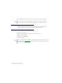
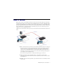
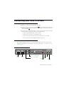
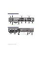
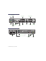
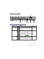
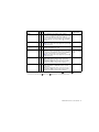
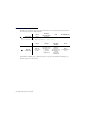
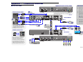
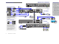
ENGLISH Matrox® Avio™ Series Avio F125 • Avio F120 User Guide 20158-301-0220 2014.05.21 Contents About this user guide ..............................................................................................4 Using this guide ........................................................................................................................................4 More information ....................................................................................................................................4 Overview ..................................................................................................................5 Features .....................................................................................................................................................5 How it works ............................................................................................................7 Connecting your Avio F125 unit .............................................................................9 Before you begin ......................................................................................................................................9 Connection overview ...............................................................................................................................9 Avio F125 Transmitter – Front ................................................................................................ 9 Avio F125 Transmitter – Back ............................................................................................... 10 Avio F125 Receiver – Front .................................................................................................... 10 Avio F125 Receiver – Back ..................................................................................................... 11 Connector descriptions .............................................................................................................11 Description of LEDs ............................................................................................................... 14 Connecting your Avio F120 unit ...........................................................................15 Before you begin ....................................................................................................................................15 Connection overview .............................................................................................................................15 Avio F120 Transmitter – Front .............................................................................................. 15 Avio F120 Transmitter – Back ............................................................................................... 16 Avio F120 Receiver – Front .................................................................................................... 16 Avio F120 Receiver – Back ..................................................................................................... 17 Connector descriptions .............................................................................................................17 Description of LEDs ............................................................................................................... 20 Validating your Avio setup ....................................................................................21 Keyboard and mouse ............................................................................................................. 21 Monitors ................................................................................................................................. 21 Optical connection ................................................................................................................. 21 Audio ...................................................................................................................................... 21 HDCP support with Matrox Avio F125 .................................................................22 2 Matrox Avio Series – User Guide Configuring your Avio product ............................................................................. 23 Accessing the OSD menus .....................................................................................................................23 OSD main menu ....................................................................................................................................23 Information ............................................................................................................................. 24 EDID management ................................................................................................................. 25 Volume .................................................................................................................................... 26 Menu options .......................................................................................................................... 26 Settings .................................................................................................................................... 27 Status bar ................................................................................................................................................28 Product information .............................................................................................. 29 Specifications .........................................................................................................................................29 Avio F125/F120 ......................................................................................................................................29 Environmental ........................................................................................................................ 29 Power consumption and supply voltage ................................................................................ 30 Audio ....................................................................................................................................... 30 Notes .......................................................................................................................................................30 Digital flat panel information ...............................................................................................................31 Appendix 1 – Connection overview .................................................................... 33 Matrox Avio F125 ..................................................................................................................................33 Matrox Avio F120 ..................................................................................................................................34 Appendix 2 – Mounting your units ....................................................................... 35 Rack mount kit ......................................................................................................................................35 Mounting guidelines ..............................................................................................................................36 Customer support ................................................................................................ 37 Matrox Web ............................................................................................................................................37 Technical support ..................................................................................................................................37 Information we need .............................................................................................................. 37 Firmware package ..................................................................................................................................37 View your warranty information ..........................................................................................................38 Register your Matrox product ...............................................................................................................38 Matrox Avio Series – User Guide 3 About this user guide Your Matrox user guide provides information on installing and using your Matrox hardware. Using this guide This guide assumes you’re familiar with basic functions like click, right-click and double-click, and that you’re familiar with the basics of the operating system you’re using. Also, we use the following conventions: Bold for headings and for references to text that appears on-screen. Italics for file names, paths, publication titles, and new terms. Bold Italics for emphasis. Keyboard keys in square brackets, with a plus sign separating keys that you press simultaneously. For example: press [Ctrl]+[Alt]+[Del] to start Windows Task Manager. Arrows (“Æ”) to separate ordered directions. For example, “click OK Æ Close Æ OK” is the same as “click OK, then click Close, then click OK”. Green for cross-references. If you’re viewing online, click green text to jump to what’s being referenced. More information Be sure to check for any last-minute release notes included with your product. Also, check the Matrox Web site (www.matrox.com/graphics) for the latest Matrox software, technical support, and product information. 4 Matrox Avio Series – User Guide Overview Thank you for purchasing a Matrox Avio product. Avio Series products are KVM (Keyboard Video Mouse) extenders that consist of a transmitter and receiver unit pair connected by a fiber optic cable. These units allow you to operate a computer up to four (4) kilometers away. These products separate your monitors, keyboard, mouse, audio, and USB devices from your computer. Features Your Matrox Avio product has the following features: Uncompressed transmission delivers exceptional image quality and smooth HD video playback without any dropped frames. Extends two (2) single-link DVI displays with a maximum resolution of 1920 x1200 or one (1) dual-link DVI display with a maximum resolution of 2560 x 1600. Supports a maximum distance of 400 m (1312 ft) in multi-mode and 10 km (6.2 mi) in single-mode (optional upgrade).* Avio F125 only – Supports transparent USB 2.0 for high-speed USB devices. Avio F125 only – Optional support of HDCP. DDC compliance and advanced EDID management ensure a reliable communication between the system and the displays connected to the receiver unit. Local connectors on the transmitter unit serve as a secondary user access to the host system. Hardware supplied† Avio F125 transmitter unit – Avio unit, multi-mode transceiver, 2 DVI-D cables, one 1 USB cable (A to B connectors), 1 power supply, 2 analog audio cables. Avio F120 transmitter unit – Avio unit, multi-mode transceiver, 2 DVI-D cables, one 1 USB cable (A to B connectors), 1 power supply. * With some USB devices using bulk write transfers, the maximum distance supported is 6 km (3.7 mi). † The hardware supplied with your Matrox product may vary depending on the SKU or part number of your product. For more information, contact your Matrox representative. Matrox Avio Series – User Guide 5 Avio F125/F120 receiver unit – Avio unit, multi-mode transceiver, 1 power supply. Note: The hardware and cables supplied have been tested to work with your Matrox product. We strongly recommend you use these cables when connecting your devices. Hardware required (sold separately) LC-LC optical cable - multi-mode (62.5/125 µm (OM1), 50/125 µm (OM2, OM3, or OM4)) or LC-LC optical cable - single-mode (9/125 µm (OS1 or OS2)) Optional hardware (sold separately) Single-mode transceivers Male-to-male audio cables with mini-stereo (3.5 mm) connectors Male-to-male PS/2 cables USB A to mini USB B cables Rack mounting kit Note: To purchase any cables or adapters not included with your Matrox product, see the Matrox online store (shopmatrox.com). For a single-mode transceiver upgrade, contact your sales representative. 6 Matrox Avio Series – User Guide How it works Matrox Avio consists of a transmitter unit and a receiver unit connected by a fiber optic cable. The transmitter unit connects to the computer using a USB cable and two (2) male-to-male PS/2 cables (one for the keyboard and one for the mouse). The receiver unit connects to your transmitter unit through a duplex LC-LC fiber optic cable. You can connect peripheral devices (such as a keyboard, a mouse, and monitors) to either or both your transmitter and your receiver. Connecting to both requires two (2) sets of peripheral devices. A Matrox Avio environment is made up of four (4) areas defined around its transmitter and receiver units: Host Optical Local Remote Host – Connections between the host system and the transmitter unit. The computer is the only host device. You must connect the video output of your graphics card to the video in connectors on your tramsitter unit and your computer to the main USB connector on your transmitter unit. To use the sound connectors at the front of your transmitter or receiver units, you also need to connect the sound input and output of your computer to the transmitter unit. Host connections require male-to-male cables with the proper connectors. Local – Connections to the transmitter unit to control the host system. These connections are optional. Local devices can be a keyboard, a mouse, monitors, sound, and USB devices. Optical – Connection through a fiber optic cable between the Avio transmitter and the receiver units. Matrox Avio Series – User Guide 7 8 Remote – Connections to the receiver unit to control the host system. Similar to the local connection, you can connect these remote devices: keyboard, mouse, monitors, sound, and USB HID devices. Matrox Avio Series – User Guide Connecting your Avio F125 unit Before you begin Make sure you have a Duplex LC-LC fiber optic cable. Monitors connected to the connectors labeled on the transmitter and receiver units use the same display and monitor settings. This also applies to monitors connected to connectors labeled . Your Avio units provide the link between your host system and your monitor, keyboard, and mouse. Before you turn on your host system, make sure you: connect your transmitter unit to your host system connect your receiver unit to your transmitter unit connect your monitors, keyboard, mouse, and other devices to your units turn on your devices and units after everything is connected Connection overview This section describes the connectors on your Avio F125 transmitter and receiver units. For more information on the OSD (On-Screen Display) controls of your Avio units, see “Configuring your Avio product”, page 23. Avio F125 Transmitter – Front PS/2 keyboard (local) USB HID (local) USB 2.0 (local) PS/2 mouse (local) Line-in (local) Microphone (local) Headphones Line-out (local) (local) Matrox Avio Series – User Guide 9 Avio F125 Transmitter – Back PS/2 mouse (host) Line-in (host) DVI-D SL/DL * (host) Dedicated USB links (host) Line-out (host) PS/2 keyboard (host) DVI-D SL (host) VGA+DVI SL/DL * (local) SFP+ 12V DC VGA+DVI SL power input (local) Main USB (host) Avio F125 Receiver – Front PS/2 mouse (remote) USB HID (remote) USB 2.0 (remote) 10 Matrox Avio Series – User Guide Line-in (remote) Microphone PS/2 keyboard (remote) (remote) Headphones Line-out (remote) (remote) Avio F125 Receiver – Back VGA+DVI SL/DL * (remote) Debug SFP+ VGA+DVI SL 12V DC (remote) power input RX Connector TX Connector descriptions Description Required host connection 12V DC power input 9 9 Connect the 12V DC power supply included with your product to this connector. While the 12V DC power supply is connected to the unit and electrical socket, the power LED ( ) is active (green). Dedicated USB links 9 For host systems that don’t support keyboards and mice through a USB hub, connect your host system to the dedicated mouse and keyboard connectors on your transmitter unit to support a keyboard and mouse on your receiver unit. A USB A to mini-B cable is required to connect to each of these connectors. To purchase these cables, see the Matrox online store (shopmatrox.com). Note: Your Avio unit only supports up to USB 2.0 connectors. DVI-D SL/DL* 9 Using the DVI-D cable provided with your transmitter unit, connect the primary graphics connector of your graphics hardware to this connector on your transmitter unit. Note: Your Avio unit only supports digital input signals. Matrox Avio Series – User Guide 11 RX TX Connector Description Required host connection DVI-D SL* 9 Headphones 9 9 Connect your headphones to this connector. This connector supports a 3.5 mm stereo jack. While headphones are connected, the line-out connector remains enabled. Line-in Line-in 9 9 Connect the line-out connector of your computer (host) or of another audio device (local or remote) to this connector. This connector supports a 3.5 mm stereo jack. Line-out Line-out 9 9 Connect the line-in connector of your computer (host) or of another audio device (local or remote) to this connector. This connector supports a 3.5 mm stereo jack. Line-in Main USB 9 Microphone 9 9 Connect your microphone to this connector. This connector supports a 3.5 mm stereo jack. Line-out PS/2 keyboard 9 9 Connect your PS/2 keyboard to this connector. Host: To be able to connect your computer to the host PS/2 keyboard connector on your transmitter, you need a male-to-male PS/2 cable. To purchase this cable, see the Matrox online store (shopmatrox.com). PS/2 keyboard PS/2 mouse 9 9 Connect your PS/2 mouse to this connector. Host: To be able to connect your computer to the host PS/2 mouse connector on your transmitter, you need a male-to-male PS/2 cable. To purchase this cable, see the Matrox online store (shopmatrox.com). PS/2 mouse Using the DVI-D cable provided with your transmitter unit, connect the secondary graphics connector of your graphics hardware to this connector on your transmitter unit. Note: Your Avio unit only supports digital input signals. Use the USB cable provided to connect your computer to your transmitter unit. This connection is required to use supported USB devices on your transmitter and receiver units. Note: For host systems that don’t support keyboards and mice through a USB hub at startup, you need to use the dedicated USB connectors if you’re using a USB keyboard and mouse. Your Avio unit only supports up to USB 2.0 connectors. * While using a Dual-Link display resolution (such as 2560 x 1600) with the connectors of your units, the 12 Matrox Avio Series – User Guide DVI SL and DVI SL/DL and VGA+DVI SL connectors are disabled. VGA+DVI SL/DL RX TX Connector Description Required host connection SFP+ 9 9 Use a Duplex LC-LC fiber optic cable to connect your Avio transmitter and receiver units to each other. While a fiber optic cable is connected to the unit and your unit is plugged in, the optical connection LED ( ) is active (green). USB 2.0 9 9 Connect your USB devices to this connector. Note: Your Avio unit only supports up to USB 2.0 connectors. Main USB or Dedicated USB links 9 This USB connector is reserved for Matrox technical support use only. Debug USB HID 9 9 Connect only your USB HIDs (Human Interface Devices, such as keyboard and mouse) to this connector. A maximum of three (3) USB HIDs can be connected to your receiver unit. Note: Your Avio unit only supports up to USB 2.0 connectors. Main USB or Dedicated USB links VGA+DVI SL* 9 9 Connect your analog (VGA) monitor or digital (DVI) single-link monitor to this connector. Monitors attached to this connector on the transmitter and receiver units use the same display resolution and monitor settings. DVI-SL VGA+DVI SL/DL* 9 9 Connect your analog (VGA) monitor or digital (DVI) single-link or dual-link monitor to this connector. Monitors attached to this connector on the transmitter and receiver units use the same display resolution and monitor settings. DVI-SL/DL * While using a dual-link display resolution (such as 2560 x 1600) with the connectors of your units, the DVI SL and DVI SL/DL and VGA+DVI SL/DL VGA+DVI SL connectors are disabled. Matrox Avio Series – User Guide 13 Description of LEDs The LEDs on your Matrox unit provide status information on your unit and its optical connection. The following describes the different LEDs: Power and status Green Flashing Green/Orange Red No LED (black) Unit is operational. Firmware mismatch *. Error detected. No power. * For more information on how to update your firmware, see “Settings”, page 27. Green Optical connection Optical connection active. Orange Flashing Orange Red No transceiver detected or no optical connection established. Firmware update in progress. No transceiver detected or no optical connection established. Major communication error. If both LEDs are flashing green, a firmware update is in progress. If both LEDs are flashing red, a firmware update error was detected. 14 Matrox Avio Series – User Guide Connecting your Avio F120 unit Before you begin Make sure you have a Duplex LC-LC fiber optic cable. Monitors connected to the connectors labeled on the transmitter and receiver units use the same display and monitor settings. This also applies to monitors connected to connectors labeled . Your Avio units provide the link between your host system and your monitor, keyboard, and mouse. Before you turn on your host system, make sure you: connect your transmitter unit to your host system connect your receiver unit to your transmitter unit connect your monitors, keyboard, mouse, and other devices to your units turn on your devices and units after everything is connected Connection overview This section describes the connectors on your Avio F120 transmitter and receiver units. For more information on the OSD (On-Screen Display) controls of your Avio units, see “Configuring your Avio product”, page 23. Avio F120 Transmitter – Front PS/2 keyboard (local) USB HID (local) USB 2.0 (local) PS/2 mouse (local) Line-in (local) Microphone (local) Headphones Line-out (local) (local) Matrox Avio Series – User Guide 15 Avio F120 Transmitter – Back PS/2 mouse (host) Line-in (host) Line-out (host) Dedicated USB links (host) PS/2 keyboard (host) DVI-D SL/DL * (host) DVI-D SL (host) VGA+DVI SL/DL * (local) SFP+ 12V DC VGA+DVI SL power input (local) Main USB (host) Avio F120 Receiver – Front PS/2 keyboard (remote) USB HID (remote) 16 Matrox Avio Series – User Guide PS/2 mouse (remote) Line-in (remote) Microphone (remote) Headphones Line-out (remote) (remote) Avio F120 Receiver – Back VGA+DVI SL/DL * (remote) Debug SFP+ VGA+DVI SL 12V DC (remote) power input RX Connector TX Connector descriptions Description Required host connection 12V DC power input 9 9 Connect the 12V DC power supply included with your product to this connector. While the 12V DC power supply is connected to the unit and electrical socket, the power LED ( ) is active (green). Dedicated USB links 9 For host systems that don’t support keyboards and mice through a USB hub at startup, connect your host system to the dedicated mouse and keyboard connectors on your transmitter unit to support a keyboard and mouse on your receiver unit. A USB A to mini-B cable is required to connect to each of these connectors. To purchase these cables, see the Matrox online store (shopmatrox.com). Note: Your Avio unit only supports up to USB 2.0 connectors. DVI-D SL/DL* 9 Using the DVI-D cable provided with your transmitter unit, connect the primary graphics connector of your graphics hardware to this connector on your transmitter unit. Note: Your Avio unit only supports digital input signals. Matrox Avio Series – User Guide 17 RX TX Connector Description Required host connection DVI-D SL* 9 Headphones 9 9 Connect your headphones to this connector. This connector supports a 3.5 mm stereo jack. While headphones are connected, the line-out connector remains enabled. Line-in Line-in 9 9 Connect the line-out connector of your computer (host) or of another audio device (local or remote) to this connector. This connector supports a 3.5 mm stereo jack. Line-out Line-out 9 9 Connect the line-in connector of your computer (host) or of another audio device (local or remote) to this connector. This connector supports a 3.5 mm stereo jack. Line-in Main USB 9 Microphone 9 9 Connect your microphone to this connector. This connector supports a 3.5 mm stereo jack. PS/2 keyboard 9 9 Connect your PS/2 keyboard to this connector. PS/2 keyboard Host: To be able to connect your computer to the host PS/2 keyboard connector on your transmitter, you need a male-to-male PS/2 cable. To purchase this cable, see the Matrox online store (shopmatrox.com). PS/2 mouse 9 9 Connect your PS/2 mouse to this connector. Host: To be able to connect your computer to the host PS/2 mouse connector on your transmitter, you need a male-to-male PS/2 cable. To purchase this cable, see the Matrox online store (shopmatrox.com). Using the DVI-D cable provided with your transmitter unit, connect the secondary graphics connector of your graphics hardware to this connector on your transmitter unit. Note: Your Avio unit only supports digital input signals. Use the USB cable provided to connect your computer to your transmitter unit. This connection is required to use supported USB devices on your transmitter and receiver units. Note: For host systems that don’t support keyboards and mice through a USB hub at startup, you need to use the dedicated USB connectors if you’re using a USB keyboard and mouse. Your Avio unit only supports up to USB 2.0 connectors. * While using a Dual-Link display resolution (such as 2560 x 1600) with the connectors of your units, the 18 Matrox Avio Series – User Guide DVI SL and DVI SL/DL and VGA+DVI SL connectors are disabled. Line-out PS/2 mouse VGA+DVI SL/DL RX TX Connector Description Required host connection SFP+ 9 9 Use a Duplex LC-LC fiber optic cable to connect your Avio transmitter and receiver units to each other.While a fiber optic cable is connected to the unit and your unit is plugged in, the optical connection LED ( ) is active (green). USB 2.0 9 Connect your USB devices to this connector. Note: Your Avio unit only supports up to USB 2.0 connectors. Main USB 9 This USB connector is reserved for Matrox technical support use only. Debug USB HID 9 9 Connect only your USB HIDs (Human Interface Devices, such as keyboard and mouse) to this connector. A maximum of three (3) USB HIDs can be connected to your receiver unit. Note: Your Avio unit only supports up to USB 2.0 connectors. Main USB or Dedicated USB links VGA+DVI SL* 9 9 Connect your analog (VGA) monitor or digital (DVI) single-link monitor to this connector. Monitors attached to this connector on the transmitter and receiver units use the same display resolution and monitor settings. DVI-SL VGA+DVI SL/DL* 9 9 Connect your analog (VGA) monitor or digital (DVI) single-link or dual-link monitor to this connector. Monitors attached to this connector on the transmitter and receiver units use the same display resolution and monitor settings. DVI-SL/DL * While using a dual-link display resolution (such as 2560 x 1600) with the connectors of your units, the DVI SL and DVI SL/DL and VGA+DVI SL/DL VGA+DVI SL connectors are disabled. Matrox Avio Series – User Guide 19 Description of LEDs The LEDs on your Matrox unit provide status information on your unit and its optical connection. The following describes the different LEDs: Power and status Green Flashing Green/Orange Red No LED (black) Unit is operational. Firmware mismatch *. Error detected. No power. * For more information on how to update your firmware, see “Settings”, page 27. Green Optical connection Optical connection active. Orange Flashing Orange Red No transceiver detected or no optical connection established. Firmware update in progress. No transceiver detected or no optical connection established. Major communication error. If both LEDs are flashing green, a firmware update is in progress. If both LEDs are flashing red, a firmware update error was detected. 20 Matrox Avio Series – User Guide Validating your Avio setup Here are some areas you should check to make sure your Avio is properly set up. Before you begin, make sure the power LED ( ) on your Avio units is active (green). Keyboard and mouse The keyboard and mouse on your Avio units must support the same connector type as the connection of your transmitter unit to your host system (PS/2 or USB). If your transmitter unit is connected through the standard USB connector, your host system must support a keyboard through a USB hub to support a keyboard on your receiver unit. For host systems that don’t support keyboards and mice though a USB hub, connect your transmitter unit to your host system using both the standard USB and the dedicated USB connectors for mouse and keyboard. Monitors Make sure you’re using the DVI-D cable provided with your transmitter unit to connect the graphics hardware of your host system to your transmitter unit. Monitors on connectors labeled support the same settings. on your transmitter and receiver units have to Monitors on connectors labeled support the same settings. on your transmitter and receiver units have to If you’re using a dual-link monitor on connector If you’re using an analog monitors, make sure the EDID mode used by your Avio units is an active EDID mode. For more information, see “EDID management”, page 25. , connector is disabled. Optical connection If the power LED ( ) is active (green) but the optical connection LED ( transmission (LED is either orange or red): ) detects no valid Make sure your transceiver (SFP+) is properly inserted. Make sure you’re using the proper fiber optic cable. Make sure your optical cables are properly connected on your Avio units. To use audio on your Avio units, the line-in and line-out from your host system must be respectively connected to the line-out and line-in connectors of your transmitter unit. Audio Matrox Avio Series – User Guide 21 HDCP support with Matrox Avio F125 Matrox Avio F125 units support HDCP (High-Definition Copy Protection) for the playback of copyprotected content. By default, HDCP support is disabled. To enable this feature on Avio F125 units, open the OSD and Settings menu and make sure Disable HDCP is cleared. Note: For a firmware package supporting this feature, contact your Matrox sales representative or Matrox Technical Support. Note: Make sure you’re using an HDCP compliant graphics card and HDCP compliant monitors and cables. MAC® only – If HDCP is enabled, the monitor connected to your transmitter unit may show a gray screen even if copy-protected content isn’t shown because Apple® computers validate HDCP at startup. While playing back copy-protected content: If a monitor is connected to the receiver unit, it shows the copy-protected content. The monitor connected to the transmitter unit shows a gray screen To view the desktop on the monitor connected to your transmitter unit, press the OSD menu button on your transmitter unit. This disables HDCP and stops playback. To restart playback, press Play in your video player program. Opening the OSD menu on the receiver unit disables HDCP. During this time, the screen behind the OSD menu is gray. To restart playback, press Play in your video player program. Opening the OSD menu on the transmitter unit without disabling HDCP doesn’t affect playback. 22 Matrox Avio Series – User Guide Configuring your Avio product This section describes the Avio OSD (On-Screen Display) menu, options, and controls. With the OSD menu, you can configure and view information on your units. Accessing the OSD menus To view the OSD menu, press the Menu button ( ) on your Avio unit. The menu appears on the screen of the monitors connected to your unit. To navigate through the menu or to select the value of a control, use the Up ( ) and Down ( ) buttons on your unit. To open a menu or confirm a selection, press the Enter button ( ). Menu Reset Down Up Enter OSD main menu Note: This guide has references specific to version 1.3.0.x of the Avio firmware package. A newer version of the firmware may have different menus, options, and controls. The OSD menu of your Avio product has the following options: Information – to view information on your connection status, fiber optic transceiver, and Avio unit. EDID management – to select how monitor settings are provided to your host system. Volume – to control the volume of the audio inputs and outputs of your unit. Menu options – to view the options for the OSD menu. Settings – to view additional settings for your Avio unit. Matrox Avio Series – User Guide 23 Information This menu allows you to view the following: Connection status of your optical link, the resolution, and the frequency used by your monitor connectors. It also lists if monitors are connected to your transmitter and receiver units. Information on your optical transceiver such as model, part number, serial number, laser wavelength, temperature, and electrical data. Temperature of the main controller of your Avio unit. Model and serial number of your Avio unit, and the version number of the firmware package. In case of a firmware mismatch, it also provides the numbers of the various firmware in the package. 24 Matrox Avio Series – User Guide EDID management This menu allows to select which EDID settings are provided to your host system by your transmitter and receiver units. Your Avio product supports two (2) EDID modes: Active – Uses the EDID settings of the monitor on the connector. While using this mode, the EDID settings of the monitor connected to your receiver unit are used first. If no monitor is detected on your receiver unit (for example, your monitor or optical cable is disconnected), the settings of the monitor connected to your transmitter unit are used. Disconnecting your optical cable has the same effect as disconnecting the monitors on your receiver unit. To manually reset EDID management to use this mode, press and hold the Up ( button, then press the [Reset] button with the tip of a paperclip. ) Fixed – Uses the EDID settings for a selected resolution and refresh rate, or uses the EDID settings from a monitor connected to your transmitter or receiver unit. The EDID settings are stored on your transmitter unit. These settings are used until you update them or until you change the EDID mode. Disconnecting your optical cable has no effect as the EDID settings for your monitors are always the settings saved on your transmitter unit. Matrox Avio Series – User Guide 25 Volume This menu allows you to set the volume for the audio output connectors on your unit. You can also mute all audio connectors on your unit. Menu options This menu allows you to choose to list the temperature in Celsius or Fahrenheit, set the transparency level of the menu and the text, and choose the amount of time before the OSD menu closes automatically. 26 Matrox Avio Series – User Guide Settings This menu allows you to view the following: Disable the OSD buttons on one or both of your units. If you disable the OSD buttons, you can access the OSD menu by quickly pressing [Reset] with the tip of a paperclip. Avio F125 only – Disable HDCP. For more information on HDCP support, see “HDCP support with Matrox Avio F125”. Reset all options and settings of your units. Restart your units. Standardize the firmware of your units by updating the firmware of one unit with the firmware of the other unit. Force your output to use an analog or a digital signal. Update the firmware of your units with a firmware version stored on an external source connected to the mouse USB connector. You can also restore the firmware to the factory default version for your unit. Note: Firmware mismatch isn’t supported. Your Avio transmitter and receiver units must be using the same firmware package version. Matrox Avio Series – User Guide 27 Status bar The OSD menu status bar provides information on your Avio products. Dual-link indicator Unit status indicators Monitor indicator The dual-link indicator ( connector of your units. ) appears when using a dual-link resolution on the first The unit status indicators ( ) provide information on your transmitter, your receiver, and their connection status. The unit icon indicates if the firmware package is correct ( ) or incorrect ( ). The connection icon indicates if your units are connected ( ) or disconnected ( ). It also indicates a firmware mismatch ( ) between the two units. The monitor indicator identifies the monitor where the menu appears ( same number used for EDID management. 28 Matrox Avio Series – User Guide or ). It’s the Product information Specifications Avio F125/F120 Monitors supported Supported resolutions Transmitter Receiver 2 single-link or 1 dual-link 2 single-link or 1 dual-link All single-link DVI and dual-link DVI resolutions Video input connectors 2× DVI-D — Video output connectors 2× DVI-I 2× DVI-I Dimensions 21.59 cm × 4.19 cm × 13.56 cm / 8.5" × 1.65" × 5.34" Laser emissions 850 nm laser compliant to 21CFR, Subpart J, Class 1 EMC Certifications Class A: ACMA, CE, FCC, VCCI, Korean notice Environmental Temperature, operational * 5 to 40 ºC (41 to 104 ºF) Temperature, non-operational storage and transportation -40 to 70 ºC ( -40 to 158 ºF) Humidity, operational (indoor) 20 to 80% (non-condensing) Humidity, non-operational storage and transportation 5% to 95% (non-condensing) Atmospheric pressure, operational 650hPa (3,580 meters / 11,745 feet) to 1013hPa (0 meters / 0 feet) Atmospheric pressure, non-operational and transportation 192hPa (12,000 meters / 39,370 feet) to 1020hPa (-50 meters / -164 feet) * Support for a maximum operating temperature of 55 degrees Celsius is available with an optional upgrade kit. Please contact your Matrox representative for more information. Matrox Avio Series – User Guide 29 Power consumption and supply voltage Avio F125/F120 unit Power requirements Power connector 12V DC, maximum 2.5 A (2.5 A fuse for overcurrent protection) DIN 4 female (4-pin) External power supply Input AC voltage range 100 to 240 V AC Input frequency 50-60 Hz Input connector IEC 60320-C14 Output voltage +12 V DC Output connector DIN 4 male (4-pin) with lock Maximum power consumption 30 W Audio Stereo audio 2 channel Bits per sample 24 bits per channel, 2 channel (Left and Right) Sampling rate 96 kHz Audio connector type Stereo crosstalk 3.5 mm stereo audio jacks -80 dB Full-scale voltage 1 VRMS (2.83 VP-P) Minimum impedance 10k Ohms Total Harmonic distortion and Noise (THD+N) < -80 dB Signal-to-noise ratio (SNR) >76 dBA Notes Your Matrox product is 100% VGA compatible and supports all VESA® standards: VBE 3.0 (Super VGA modes), DPMS (energy saving), DDC-2B (Plug-and-Play monitor), and DDC-CI. 30 Matrox Avio Series – User Guide The display resolutions and refresh rates available depend on your graphics hardware, display driver, software monitor settings, and monitor. For information on the capabilities of your monitor, see your monitor documentation. Your transmitter and receiver units use the same multi-display configuration and monitor settings (such as display resolution and refresh rate). You must use products from the same models at the same time (for example, you can use two F120 products, but you can’t use a F125 product and a F120 product). Digital flat panel information TMDS® (Transition Minimized Differential Signaling) encoding for DVI connectors DDWG (Digital Display Working Group) compliant DVI connector EDID (Extended Display Identification Data) 1.2 and 1.3 support VESA Display Data Channel (DDC) support Matrox Avio Series – User Guide 31 32 Matrox Avio Series – User Guide Appendix 1 – Connection overview Matrox Avio F125 Host connections Optional local connections 6 Local connections on your transmitter unit are optional and are similar to the ones supported on your receiver unit. DVI-D Connection setup 1 Connect your monitors to your units. 2 Connect your keyboard and mouse to your units. 3 Connect your fiber optic cable. 4 Connect the USB cable to your host system and your transmitter unit (main USB connection). Front Note: This connector doesn’t support USB 3.0 connections. You must use USB 2.0 connections. Transmitter 7 Back 12 VDC 2.5A Max 5 Dedicated USB connections Dedicated USB connections are only required if, when starting, your host computer can’t detect a USB keyboard or mouse on your transmitter or receiver unit. Main USB connection 4 Connect the power supply of your units. 6 Connect the graphics hardware of your host system to your transmitter unit. 7 Turn on your host system. 3 LC-LC Duplex fiber optic cable 12 VDC 2.5A Max 5 Back PS/2 connectors 5 Receiver 1 Front To use a PS/2 mouse or keyboard with your receiver or transmitter units, your system must be connected to the keyboard and mouse PS/2 connectors at the back of your transmitter unit and your keyboard and mouse connected to at least one of your units before your system and units are powered on. 2 Matrox Avio Series – User Guide 33 Optional local connections Matrox Avio F120 Host connections 6 Local connections on your transmitter unit are optional and are similar to the ones supported on your receiver unit. DVI-D Connection setup 1 Connect your monitors to your units. 2 Connect your keyboard and mouse to your units. 3 Connect your fiber optic cable. 4 Connect the USB cable to your host system and your transmitter unit (main USB connection). Front Note: Your Avio unit only supports up to USB 2.0 connectors. Transmitter 7 Back 12 VDC 2.5A Max 5 Dedicated USB connections Dedicated USB connections are only required if, when starting, your host system can’t detect a USB keyboard or mouse on your receiver unit. Main USB connection 4 Connect the graphics hardware of your host system to your transmitter unit. 7 Turn on your host system. LC-LC Duplex fiber optic cable 5 Back Front Matrox Avio Series – User Guide 6 3 Receiver 34 Connect the power supply of your units. 12 VDC 2.5A Max PS/2 connectors To use a PS/2 mouse or keyboard with your receiver or transmitter units, your system must be connected to the keyboard and mouse PS/2 connectors at the back of your transmitter unit and your keyboard and mouse connected to at least one of your units before your system and units are powered on. 5 2 1 Appendix 2 – Mounting your units This section provides guidelines for mounting your Avio unit using the rack mounting kit (sold separately). To purchase the rack mounting kit, contact your Matrox sales representative. Rack mount kit Your Avio unit can be mounted on a 19-inch mounting shelf. You can mount two (2) units side by side on a single shelf. To install your mounting shelf, fasten it to the rack as per your rack’s instructions. Head screws compatible with most rack mounts are provided. The mounting shelf has existing holes for your Avio unit that allow the shelf to be mounted facing forward or backward. These holes are labeled A on the underside of your mounting shelf. To respect the height of a 1U shelf, you need to remove the four (4) rubber pads under your Avio unit before you secure the unit to the shelf. Your Avio unit has two (2) mounting holes under its casing. Use two (2) 6 mm M3 mounting screws provided with your mounting shelf to secure each unit. Use a hand screwdriver to carefully tighten each screw. Make sure not to overtighten the screws. Matrox Avio Series – User Guide 35 Mounting guidelines To prevent damage to your Matrox hardware, read the following guidelines before mounting your Matrox hardware: Make sure not to block the ventilation holes on your unit. Don’t stack anything directly over the unit. Make sure the cables connected to your unit are properly secured and that no tension is applied to them. Make sure the ambient temperature doesn’t exceed the maximum recommended temperatures. For more information, see “Environmental”, page 29. Once your Avio unit is mounted, you can connect your system, monitors, and devices to your Avio unit. 36 Matrox Avio Series – User Guide Customer support Matrox Web Our Web site has product literature, press releases, technical material, a sales office list, trade show information, and other relevant material. Visit the Matrox Graphics Web site at www.matrox.com/graphics. Technical support Matrox values your business and offers professional support for your Matrox product. If your product was purchased through a Matrox dealer, contact your dealer for product support. This is the quickest and most effective method of technical assistance. Your dealer is familiar with your complete system. If your product was purchased through Matrox, contact your Matrox representative or visit our technical support Web site at www.matrox.com/graphics/support. Information we need Please give a complete description of the problem, and include: Matrox product serial number, model number, revision number, and firmware version. Computer brand and model name. Graphics card manufacturer, model number, revision number, BIOS number, driver type and version. Monitors brand and model name. Operating system, version, and service pack. Firmware package A more recent firmware package may support more features and may offer increased capabilities (such as support for higher display resolutions). To obtain the latest firmware package, contact your Matrox sales representative or Matrox Technical Support. Matrox Avio Series – User Guide 37 View your warranty information Matrox makes warranty information available on the Matrox site (http://www.matrox.com/hr/en/company/legal/en/warranty). Register your Matrox product Please register online (www.matrox.com/graphics/en/registration) to be eligible for customer support, new product announcements, and information on special offers and upcoming events. 38 Matrox Avio Series – User Guide USA FCC Compliance Statement Compliance Remark for the Matrox hardware products supported by this guide This equipment has been tested and found to comply with the limits for a Class A digital device, pursuant to Part 15 of the FCC Rules. These limits are designed to provide reasonable protection against harmful interference when the equipment is operated in a commercial environment. This equipment generates, uses, and can radiate radio frequency energy and, if not installed and used in accordance with the instructions manual, may cause harmful interference to radio communications. Operation of this equipment in a residential area is likely to cause harmful interference in which case the user will be required to correct the interference at his own expense. WARNING Changes or modifications to this unit not expressly approved by the party responsible for the compliance could void the user’s authority to operate this equipment. The use of shielded cables for connection of the monitor to the card is required to meet FCC requirements. CANADA (English) Industry Canada Compliance Statement Remark for the Matrox hardware products supported by this guide These digital apparatus does not exceed the Class A limits for radio noise emission from digital devices set out in the Radio Interference Regulation of Industry Canada. (Français) Conformité avec les exigences du ministère de l’Industrie Canada Remarque sur les produits matériels Matrox couverts par ce guide Ce present appareil numérique n’émet aucun bruit radioélectrique dépassant les limites applicables aux appareils numériques de Classe A prescrites dans le Règlement sur le brouillage radioélectrique édicté par Industrie Canada. USA (English) FDA (Food and Drug Administration) requirements for Laser Products Remark for the Matrox hardware products supported by this guide Product compliant to 21CFR Subpart J Class 1. This product includes a 850 nm Laser JAPAN VCCI Compliance Statement Remark for the Matrox hardware products supported by this guide This is a Class A product based on the standard of the Voluntary Control Council for Interference by Information Technology Equipment (VCCI). If this equipment is used in a domestic environment, radio disturbance may occur, in which case, the user may be required to take corrective actions. KOREA KCC 전자파 적합 등록 안내 (Class A) 이 기기는 업무용 (A 급 ) 으로 전자파적합등록을 한 기기이오니 판매자 또는 사용자는 이 점 을 주의하시기 바라며 , 가정 이외의 지역에서 사용할 수 있습니다 . EUROPE (English) European user’s information – Declaration of Conformity Remark for the Matrox hardware products supported by this guide These devices comply with EC Directive 2004/108/EC for a Class A digital device. They have been tested and found to comply with EN55022/CISPR22 and EN55024/CISPR24. In a domestic environment these products may cause radio interference in which case the user may be required to take adequate measures. To meet EC requirements, shielded cables must be used to connect the monitor and other peripherals to the card. These products have been tested in a typical class A compliant host system. It is assumed that these products will also achieve compliance in any class A compliant system. (Français) Informations aux utilisateurs Européens – Déclaration de conformité Remarque sur les produits matériels Matrox couverts par ce guide Ces unités sont conformes à la directive communautaire 2004/108/EC pour les unités numériques de classe A. Les tests effectués ont prouvé qu’elles sont conformes aux normes EN55022/CISPR22 et EN55024/CISPR24. Le fonctionnement de ces produits dans un environnement résidentiel peut causer des interférences radio, dans ce cas l’utilisateur peut être amené à prendre les mesures appropriées. Pour respecter les impératifs communautaires, les câbles de connexion entre le moniteur ou autres périphériques et la carte doivent être blindés. Ces produits ont été testés dans un système hôte typique compatible classe A. On suppose qu’ils présenteront la même compatibilité dans tout système compatible classe A. (Deutsch) Information für europäische Anwender – Konformitätserklärung Anmerkung für die Matrox Hardware-Produktunterstützung durch dieses Handbuch Diese Geräte entsprechen EC Direktive 2004/108/EC für ein digitales Gerät Klasse A. Sie wurden getestet und entsprechen demnach EN55022/CISPR22 und EN55024/CISPR24. In einer Wohnumgebung können diese Produkte Funkinterferenzen erzeugen, und der Benutzer kann genötigt sein, entsprechende Maßnahmen zu ergreifen. Um EG-Anforderungen zu entsprechen, müssen zum Anschließen des Monitors und anderer Peripheriegeräte an die Karte abgeschirmte Kabel verwendet werden. Diese Produkt wurden in einem typischen, der Klasse A entsprechenden, Host-System getestet. Es wird davon ausgegangen, daß diese Produkte auch in jedem Klasse A entsprechenden System entsprechend funktionieren. (Italiano) Informazioni per gli utenti europei – Dichiarazione di conformità Nota per i prodotti hardware Matrox supportati da questa guida Questi dispositivi sono conformi alla direttiva CEE 2004/108/EC relativamente ai dispositivi digitali di Classe A. Sono stati provati e sono risultati conformi alle norme EN55022/CISPR22 e EN55024/CISPR24. In un ambiente domestico, questi prodotti possono causare radiointerferenze, nel qual caso all’utente potrebbe venire richiesto di prendere le misure adeguate. Per soddisfare i requisiti CEE, il monitor e le altre periferiche vanno collegati alla scheda grafica con cavi schermati. Questi prodotti sono stati provati in un tipico sistema host conforme alla classe A. Inoltre, si dà per scontato che questi prodotti acquisiranno la conformità in qualsiasi sistema conforme alla classe A. (Español) Información para usuarios europeos – Declaración de conformidad Observación referente a los productos de hardware de Matrox apoyados por este manual Estos dispositivos cumplen con la directiva de la CE 2004/108/EC para dispositivos digitales de Clase A. Dichos dispositivos han sido sometidos a prueba y se ha comprobado que cumplen con las normas EN55022/CISPR22 y EN55024/CISPR24. En entornos residenciales, estos productos pueden causar interferencias en las comunicaciones por radio; en tal caso el usuario deberá adoptar las medidas adecuadas. Para satisfacer las disposiciones de la CE, deberán utilizarse cables apantallados para conectar el monitor y demás periféricos a la tarjeta. Estos productos han sido sometidos a prueba en un típico sistema anfitrión que responde a los requisitos de la clase A. Se supone que estos productos cumplirán también con las normas en cualquier sistema que responda a los requisitos de la clase A. ROVI CORPORATION (English) This item incorporates copy protection technology that is protected by U.S. patent(s) and other intellectual property rights of Rovi Corporation. Reverse engineering and disassembly are prohibited. (Français) Ce produit intègre une technologie de protection des droits d’auteur qui est protégée par un ou plusieurs brevets américains et par d’autres droits de propriété intellectuelle de Rovi Corporation. L’ingénierie inverse et le désassemblage sont interdits. (Deutsch) Dieses Produkt enthält Kopierschutztechnologien, die durch US-Patent(e) und andere Rechte am geistigen Eigentum der Rovi Corporation geschützt ist. Reverse Engineering und Demontage sind verboten. (Italiano) Questo prodotto incorpora la tecnologia di protezione di copia protetta da uno o più brevetti USA e da altri diritti di proprietà intellettuale di Rovi Corporation. È vietato decodificare o disassemblare il prodotto. (Español) Este producto incorpora tecnología de protección de copia que está protegida por patente(s) de EE. UU. y por otros derechos de propiedad intelectual de Rovi Corporation. La ingeniería inversa y el desmontaje están prohibidos. EUROPE (English) European user’s information – Directive on Waste Electrical and Electronic Equipment (WEEE) Please refer to the Matrox Web site (www.matrox.com/environment/en/weee) for recycling information. (Français) Informations aux utilisateurs Européens – Règlementation des déchets d’équipements électriques et électroniques (DEEE) Se référer au site Web de Matrox (www.matrox.com/environment/en/weee) pour l’information concernant le recyclage. (Deutsch) Information für europäische Anwender – Europäische Regelungen zu Elektround Elektronikaltgeräten (WEEE) Bitte wenden Sie sich an der Matrox-Website (www.matrox.com/environment/en/weee) für Recycling-Informationen. (Italiano) Informazioni per gli utenti europei – Direttiva sui rifiuti di apparecchiature elettriche ed elettroniche (RAEE) Si prega di riferirsi al sito Web Matrox (www.matrox.com/environment/en/weee) per le informazioni di riciclaggio. Copyright © 2014 Matrox Graphics Inc. • (English) All rights reserved. • (Français) Tous droits réservés. • (Deutsch) Alle Rechte vorbehalten. • (Italiano) Tutti i diritti riservati. • (Español) Reservados todos los derechos. Trademarks • Marques déposées • Warenzeichen • Marchi registrati • Marcas registradas Matrox Electronic Systems Ltd. / Matrox Graphics Inc..................................................Matrox®, DualHead®, ASM™, ATC™, AuroraVX3mp™, AuroraVX™, Avio™, DualHead2Go™, Epica™, Equinox™, Extio™, G400™, G450™, G550™, GXM™, Maevex™, Marvel™, MED2mp™, MED2mp-DVI™, MED3mp-DVI™, MED4mp™, MED5mp-DVI™, MED5mp™, Millennium™, MMS™, Multi-Monitor Series™, MultiDesk™, Mura™, MuraControl™, Mura MPX™, Mystique™, P650™, P690™, P750™, Parhelia™, Parhelia™ APVe, Parhelia-512™, Parhelia-LX™, Parhelia HR256™, PJ4OLP™, QID™, Quad Information Display™, RAD™, Quick Connect™, MaxVIEW™, Onyx™, PixelTOUCH™, PrecisionCAD™, Precision SGT™, QuickDesk™, RAD2mp™, RAD3mp™, RAD9mp™, RADQ2mp™, Rainbow Runner®, TheatreVUE™, TripleHead™, TripleHead2Go™, VDA™, Veos™, Xenia™ Adobe Systems Inc. .................................................Acrobat®, Reader® Apple Computer, Inc. ...............................................App Store®, Apple®, iPad®, Mac®, Mac OS® Belden Inc. ...............................................................Belden® Cisco Systems Inc. ..................................................iOS® Dolby Laboratories, Inc. ............................................Dolby®, Dolby Digital® Intel Corporation .......................................................Intel®, Pentium®, Thunderbolt™s Linus Torvalds ...........................................................Linux® Microsoft Corporation ...............................................Aero®, Direct3D®, DirectShow®, DirectX®, Microsoft®, MS-DOS®, PowerPoint®, Windows®, Windows NT®, Windows Server®, Windows Vista® PCI-SIG .....................................................................PCI™, PCI-X®, PCIe®, PCI Express® Radio Corporation of America ..................................RCA® Rovi Corporation .......................................................Macrovision® SD-3C, LLC ...............................................................SD™, SDHC™, SDXC™ Silicon Graphics, Inc. ................................................OpenGL® Silicon Image, Inc......................................................PanelLink®, TMDS® U.S. Environmental Protection Agency .....................ENERGY STAR® Video Electronics Standards Association .................DisplayPort™ VideoLAN ..................................................................VideoLAN®, VLC®, VLC® media player, VNC® Wibu-Systems...........................................................WIBU® Copyright © 1996-2014 VideoLAN. This logo or a modified version may be used or modified by anyone to refer to the VideoLAN project or any product developed by the VideoLAN team, but does not indicate endorsement by the project. HTML5 Logo by World Wide Web Consortium (W3C). This HTML5 logo is licensed under this Public License (http://www.creativecommons.org/licenses/by/3.0/legalcode). The logo has been modified to meet the resolution and size required by this application. HDMI, the HDMI logo, and High-Definition Multimedia Interface are trademarks or registered trademarks of HDMI Licensing LLC. SD, SDHC and SDXC Logos are trademarks of SD-3C, LLC. • (English) Registered trademarks are registered in the United States, Canada, and/or other countries. All other nationally and internationally recognized trademarks and tradenames are hereby acknowledged. • (Français) Les marques déposées sont déposées aux États-Unis, au Canada et/ou dans d’autres pays. Toutes les autres marques et tous les autres noms déposés reconnus nationalement ou internationalement sont également reconnus par les présentes. • (Deutsch) Die eingetragenen Warenzeichen sind in den USA, Kanada und/oder anderen Ländern registriert. Alle sonstigen national und international bekannten Warenzeichen und Produktnamen werden hiermit anerkannt. • (Italiano) I marchi registrati sono registrati negli Stati Uniti, in Canada e/o in altri paesi. Tutti gli altri marchi registrati e nomi commerciali riconosciuti a livello nazionale e internazionale sono ugualmente riconosciuti qui. • (Español) Las marcas registradas están registradas en los EE.UU., Canadá u otros países. Por medio del presente se reconocen todas las demás marcas y nombres comerciales reconocidos a nivel nacional e internacional. (English) Disclaimer THE INFORMATION IN THIS GUIDE IS SUBJECT TO CHANGE AT ANY TIME AND WITHOUT NOTICE. Matrox Graphics Inc. reserves the right to make changes in specifications at any time and without notice. The information provided by this document is believed to be accurate and reliable at the time it is written. However, no responsibility is assumed by Matrox Graphics Inc. for its use, for its reproduction and/or distribution, in whole or in part; nor for any infringements of patents or other rights of third parties resulting from its use. (Français) Responsabilité LES INFORMATIONS CONTENUES DANS CE MANUEL PEUVENT ÊTRE MODIFIÉES EN TOUT TEMPS ET CE SANS PRÉAVIS. Les Graphiques Matrox Inc. se réserve le droit de modifier les spécifications en tout temps et ce sans préavis quelconque. Les informations contenues dans ce manuel sont reconnues comme étant précises et fiables à la date de rédaction. Cependant, Matrox Graphics Inc. n’assume aucune responsabilité concernant leur utilisation, leur reproduction et/ou distribution, en tout ou en partie, ni leur contrefaçon de brevets ou de tout autre droit appartenant à des tiers résultant de leur utilisation. Aucune licence n’est accordée sur aucun brevet ou droit d’exploiter un brevet de Matrox Graphics Inc. (Deutsch) Haftungsablehnungserklärung DIE IN DIESEM HANDBUCH ENTHALTENEN ANGABEN UND DATEN KÖNNEN OHNE VORHERIGE ANKÜNDIGUNG GEÄNDERT WERDEN. Die Matrox Graphics Inc. behält sich das Recht vor, jederzeit und ohne Ankündigung technische Daten zu ändern. Zum Zeitpunkt der Erstellung dieses Handbuchs sind die Inhalte korrekt und verlässlich. Weiterhin übernimmt Matrox Graphics Inc. keinerlei Verantwortung für die Benutzung dieses Handbuchs, die Vervielfältigung und/oder Verteilung im Ganzen oder zum Teil; weder für Verstöße gegen Patentrechte noch für andere Rechte Dritter, die aus seinem Gebrauch resultieren mögen. Es werden keinerlei Lizenzrechte gewährt für sämtliche Patente oder Patentrechte der Matrox Graphics Inc. (Italiano) Discrezionalità LE INFORMAZIONI CONTENUTE NEL PRESENTE DOCUMENTO SONO SOGGETTE A MODIFICHE IN QUALUNQUE MOMENTO E SENZA PREAVVISO. Matrox Graphics Inc. si riserva il diritto di apportare variazioni di qualunque tipo alle specifiche tecniche in qualunque momento e senza alcun preavviso. Le informazioni contenute in questa documentazione sono ritenute corrette e attendibili al momento della pubblicazione. In ogni caso, non è imputabile a Matrox Graphics Inc. nessuna responsabilità per il loro utilizzo, per la loro distribuzione e/o riproduzione completa o in parte, come nessuna violazione a brevetti o diritti di altri produttori derivante dal loro utilizzo. (Español) Renuncia LA INFORMACION QUE CONTIENE EL PRESENTE MANUAL ESTA SUJETA A CAMBIOS SIN PREVIO AVISO EN CUALQUIER MOMENTO. Matrox Graphics Inc. se reserva el derecho de realizar modificaciones en cualquier momento y sin previo aviso. La información facilitada en este documento se considera que es exacta y fiable hasta la fecha de publicación. Sin embargo, Matrox Graphics Inc. no asume ninguna responsabilidad por su uso, por su reproducción y/o distribución parcial o total; ni por cualquier infracción de patentes u otros derechos de terceras partes derivados de su uso. No se concede ninguna licencia bajo cualesquiera patentes o derechos de patentes de Matrox Graphics Inc. Matrox Graphics Inc. 1055 Saint Regis Boulevard Dorval, Quebec, Canada H9P 2T4 North America: 1-800-361-1408 International: (514) 822-6000 Email: [email protected] Web site: www.matrox.com/graphics Technical support: www.matrox.com/graphics/support To locate the sales office nearest you, visit www.matrox.com/graphics/contact