1
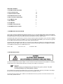
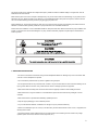
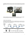
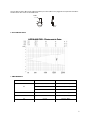
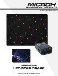
TABLE OF
F CONTENTS
1. INTRODU
UCTION AND UN
NPACKING
1
2. SAFTEY INSTRUCTIONS
S
1-2
3. OPERATION INSTRUCTIONS
2-3
4. MOUNTIN
NG AND INSTAL
LLATION
3-4
5. DMX-512 CONTROL CON
NNECTIONS
4-5
6. PHOTOM
METRIC DATA
5
7. DMX CHA
ANNELS
5
8. KEY FEA
ATURES
6
9. TECHNIC
CAL SPECIFICA
ATIONS
6
10. MAINTE
ENANCE AND CLEANING
7
1. INTROD
DUCTION AND
D UNPACKING
G
Thank you fo
or purchasing the
e MICROH LED SLIM P64 wash fixture. For yourr own safety and
d knowledge, plea
ase read this ma
anual
before installing or operating
g the device. This
s manual covers the important infformation on insttallation and app
plications. Please
e install
and operate the fixture according to instructio
ons. Meanwhile, please keep thiss manual for futu
ure reference.
The MICROH LED SLIM P64
4 wash fixture is made of a new type
t
of high temp
perature cast alu
uminum casing. T
The fixture is dessigned
and manufactured strictly following CE stand
dards, complying with internationa
al standard DMX
X512 protocol. Th
his fixture is applicable
ed to large-scale
e live performances, theater, studio, nightclubs an
nd discos.
but not limite
The MICROH LED SLIM P64
4 wash fixture us
ses 181 x 10mm LED’s (36 red, 8
85 green, 60 blue
e), which feature
e high brightnesss and
stability. Please carefully unp
pack it when you
u receive the fixtu
ure and check if iit was damaged during the transp
portation. And pllease
check wheth
her the following items are include
ed inside the box
x:
Fixture – On
ne
Power Cord – One
User Manual – O
One
2. SAFTEY
Y INSTRUCTIO
ONS
This device has left the facto
ory in perfect con
ndition. In order to maintain this ccondition and to e
ensure safe operration, it is absolu
utely
or the user to folllow the safety ins
structions and warning notes writtten in this user m
manual.
necessary fo
If the device
e has been expos
sed to temperatu
ure changes, do not
n switch it on im
mmediately. The
e arising condenssation could dam
mage
the device. Leave
L
the device
e switched off until it has reached
d room temperatu
ure, and is dry.
This device falls under prote
ection-class I, the
erefore it is essen
ntial that the dev ice be grounded . The electrical cconnection must be
b a qualified tec
chnician.
carried out by
1 The device should only be used with rate voltage and frequency. Make sure that the available voltage is not higher than 120V as
stated at the end of this manual.
Make sure the power cord is never crimped or damaged in any way, as this could cause shock and damage. If your power chord is
damaged in any way, please purchase a new cable from your local MICROH dealer. Always disconnect power, when the device is
not in use or before cleaning it. Never pull out the plug by tugging the power cord.
During initial start-up, some smoke or smell may arise. This is a normal process, and does not necessarily mean that the device is
defective. It should decrease gradually. Please do not project the beam onto combustible substances.
Fixtures cannot be installed on or near combustible substances. Keep more than 50cm distance from wall for proper ventilation and
air flow. If your fixture is or has become damaged in any way, it shall be exclusively replaced or repaired by the manufacturer to
avoid any hazard.
3. OPERATION INSTRUCTIONS
- Do not turn on the fixture if it has been through severe temperature differences. Damage may occur to the fixture. Wait
until unit is at room temperature to operate.
- The unit should be protected from any tremor or agitation during transport.
- Do not expose the fixture in any excessive heat, moisture or any environment with too much dust when installing. Do not
lay any power cables on the floor. It may cause electronic shock or damage to persons or equipment.
- Make sure to attach the safety chain and ensure the screws are properly screwed in when installing the fixture.
- Make sure the lens is in good condition. It is recommended to replace the unit if there are any damages or severe
scratches.
- Make sure the fixture is operated and installed by qualified personnel.
- Keep the original packaging in case of defective product.
- Any non-manufacturer additions, modifications or changes in any way will void all warranty.
- Please do not attempt to open unit. It is only to be serviced by an authorized technician. If this occurs, or is apparent, the
warranty will be voided.
- The fixture’s warranty will be voided if there are any malfunctions from not following the user manual or any illegal
operation (shock short circuit, electronic shock, lamp broke, etc.)
2 - To keep the LED display always on press MODE & UP simultaneously. Press MODE & OFF simultaneously for the LED
display to auto shut off after 20 seconds of inactivity.
- This unit has a total of 7 operating modes: Master/Slave, Auto, DMX, Sound Active, Colour Fade, Colour Chase and
Static Colour.
MASTER/SLAVE MODE
- By connecting the 3 pin DMX, you can daisy chain up to 30 units on master/ slave mode. Daisy chain the fixtures
together by plugging from the DMX output of the first fixture into the DMX input of the second fixture, and so on…
- On your Master fixture set the unit to either AUTO or SOUND control and select one of the internal programs.
- All slave lights must be set “S.L.A.”
AUTO-RUN MODE
- Press MODE and select “A. - -“. This will auto run through colour change and colour fade programs.
DMX MODE
- Press MODE and select “X X X” (X X X=001-512). The first fixture covers 4 DMX channels. Use the UP and DOWN
buttons to select your desired address.
SOUND ACTIVE MODE
- Press MODE and select “S.XX” (XX =00-31). Choose the level of sound sensitivity desired by pressing UP or DOWN
buttons.
COLOUR FADE MODE
- Press MODE and select “F.X.X” (X X = 01-99). Press UP or DOWN button to adjust the speed of color fade.
COLOUR CHANGE MODE
- Press MODE and select “J. X X” (X X =01-99). Press UP or DOWN button to adjust the speed of color change.
STATIC COLOUR SELECT MODE
- Press MODE and select “C.L.X” (X=0-7). Press UP or DOWN button to select desired colour. 4. MOUNTING AND INSTALLATION
Caution: For added protection, mount the fixtures in areas outside walking paths, seating areas, or in areas were the fixture might
be reached by unauthorized personnel. Before mounting the fixture to any surface, make sure that the installation area can hold a
minimum point load of 10 times the device’s weight. Fixture installation must always be secured with a secondary safety attachment,
such as an appropriate safety cable. Never stand directly below the device when mounting, removing, or servicing the fixture.
Whether installing inverted on a truss or ceiling, or set on a flat level surface (see illustration below). Be sure this fixture is kept at
least 0.5m (1.5 ft) away from any flammable materials (decoration etc.). Always use and install the supplied safety cable as a safety
measure to prevent accidental damage and/or injury in the event the clamp fails.
Mounting Points: Overhead mounting requires extensive experience, including calculating working load limits. A knowledge of the
installation material being used, and periodic safety inspection of all installation material and the fixture are all imperative and should
only be performed by a qualified technician. Improper installation can result in bodily injury and damage.
Be sure to complete all rigging and installation procedures before connecting the main power cord to the appropriate wall outlet.
Floor Mounting: Set the 2 brackets at your desired angle and aim your fixture accordingly. Please see diagram below.
3 Clamp Mou
unting: The MICR
ROH LED SLIM P64 provides a unique
u
mounting
g bracket assemb
bly that integrates 2 brackets to b
be used
to mount on a truss or the flo
oor. When mountting this fixture to
o truss, be sure tto secure an app
propriately rated clamp to the inclluded
d through the center hole. As an added safety me
easure, be sure tto attach at leastt one properly ratted safety cable to the
bracket fitted
fixture.
Regardless of the rigging op
ption you choose for your MICROH SLIM P64 wassh fixture, alwayss be sure to secu
ure your fixture w
with a
safety cable. The fixture prov
vides a built-in rig
gging point for a safety cable on the hanging braccket as illustrated above. Be sure
e to
only use the
e designated rigging point for the safety cable and
d never secure a safety cable to a carrying handle
e.
5. DMX-512 CONTROL CONNECTION
C
NS
This fixture complies
c
with intternational USITT
T DMX standards and can be use
ed with either a 3 pin or 5 pin DM
MX connector. Plug in
the provided
d 3 pin XLR cable
e to the female 3-pin
3
XLR output of your controlle
er and the other sside to the male 3-pin XLR input of the
MICROH LE
ED SLIM P64. To
o connect the uniits to DMX, you must
m
daisy chain
n the fixtures toge
ether as referred
d in the diagram b
below.
Always end your DMX-512 connection
c
with a DMX terminator.
For installatiions where the DMX
D
cable has to
o run a long dista
ance, or is in an e
electrically noisyy environment, it is recommended
d to
use a DMX terminator.
t
This helps in preventiing corruption of the digital contro
ol signal by electtrical noise. The DMX terminator is
4 simply an XL
LR plug with a 12
20 Ω resistor con
nnected between
n pins 2 and 3,wh
hich is then plugg
ged into the outp
put XLR socket o
of the
last fixture in
n the chain. Plea
ase see illustratio
ons below.
120Ω
2
3
1
PIN 3
PIN 2
6. PHOTOMETRIC DATA
A
7. DMX CH
HANNELS
CHANN
NEL
VALUE
EFFEC
CT
000-189
Dimmer(dim→
→bright)
190-250
Flash(slow→
→fast)
251-255
No function
CH2
000-255
Red(dim→b
bright)
CH3
000-255
Green(dim→
→bright)
CH4
000-255
Blue(dim→b
bright)
CH1
5 8. KEY FEATURES
- 181 x 10mm LEDs (Red 36, Green 85, Blue 60)
- LED SLIM PAR Series all Have a 40º Projection Beam Angle
- 0 - 100% Linear Dimmer with 1-18 Flashes/sec High Speed Electronic Strobe
- 4 DMX Channels
- 3 Pin XLR Input & Output
- Macros, Auto Fade, Chases
- Master/Slave, Auto, DMX, Sound Active, Colour Fade, Colour Chase & Static Colour.
- IEC AC Input & Output
- Double bracket for Floor/Truss Mounting
- Built-in Microphone
- 4 Button Digital LED Display
9. TECHNICAL SPECIFICATIONS
MODEL: LED SLIM P64
LAMP: 181 x 10mm LEDs (Red 36, Green 85, Blue 60)
OPERATING TEMPERATURE: -25°C to 45°C
VOLTAGE: 120VAC 60Hz
FUSE: 2A 250V GMA
MAX: 30W
DIMENSIONS: 8.75” x 2.5” x 11”/ 222 x 64 x 279mm
PACKING DIMENSIONS: 13.5” x 12.5” x 6.75” / 343 x 318 x 171 mm
NET WEIGHT: 4.85 lbs / 2.2 kg
GROSS WEIGHT: 6.95 lbs / 3.15 kg
WARRANTY: 2 Year Limited Warranty 6 10. MAINT
TENANCE AND
D CLEANING
The following points have to be considered during
d
the inspec
ction:
ws for installing th
he device or parts
s of the device must
m
be tightly co
onnected, and m ust not be corrod
ded.
1) All screw
2) There mu
ust not be any de
eformations on th
he housing, colour lenses, fixatio
ons or installation
n spots (ceiling, ssuspension, trusssing).
3) Mechanically moved partts must not show
w any traces of wearing
w
and mustt not rotate with u
unbalances.
4)The elec
ctric power supply
y cables must no
ot show any dam
mage, material fattigue or sedimen
nts.
Further instrructions depending on the installa
ation spot and us
sage must be ha ndled by a skille d installer or tech
hnician. Any safe
ety
issues must be resolved.
k
the fixture in
n good condition and extend the life,
l
we suggest regular cleaning to the fixture.
In order to keep
1) Clean the
e inside and outs
side lens each week to avoid the light output from
m darkening due to accumulation of dust, dirt, etc..
2) Clean the
e fan each week.
3) A detaile
ed electrical chec
ck by approved technician every three months is advised. Ensure
e the circuit conta
acts are in good
conditio
on, and prevent from
f
overheating
g.
mend a frequent cleaning
c
of the de
evice. Please use a moist, lint- fre
ee cloth. Never u
use alcohol or so
olvents.
We recomm
There are no
o serviceable parts inside the dev
vice. Please refe
er to the instructio
ons under “Insta llation instruction
ns”.
Should you need any spare parts, please ord
der genuine MICROH parts from your local dealer.
OULD EXPERIE
ENCE ANY PROB
BLEMS OR ISSU
UES PLEASE C
CONTACT MICRO
OH PROFESSIO
ONAL PRODUCTS BY
IF YOU SHO
EMAIL AT info@microhpro
i
o.com
In the eventt that your unit is defective in any
a way, please
e contact your lo
ocal dealer to o
obtain an RA number for servic
ce
repair.
ER – MICROH be
elieves that the information contained within tthis user manua
al is accurate. H
However, Microh
h is
DISCLAIME
not respons
sible for any errror or addendum
ms to this manu
ual. If you have any comments or general suggestions on how this
manual can
n be improved please
p
contact in
nfo@microhpro
o.com. Thank yo
ou. 7