1
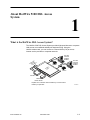
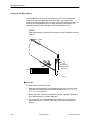
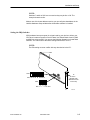
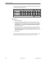
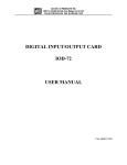
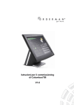
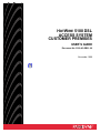
HOTWIRE 5100 DSL
ACCESS SYSTEM
CUSTOMER PREMISES
USER’S GUIDE
Document No. 5100-A2-GB21-00
November 1996
Copyright 1996 Paradyne Corporation.
All rights reserved.
Printed in U.S.A.
Notice
This publication is protected by federal copyright law. No part of this publication may be copied or distributed,
transmitted, transcribed, stored in a retrieval system, or translated into any human or computer language in any form
or by any means, electronic, mechanical, magnetic, manual or otherwise, or disclosed to third parties without the
express written permission of Paradyne Corporation, 8545 126th Avenue North, P.O. Box 2826, Largo,
Florida 33779-2826.
Paradyne Corporation makes no representation or warranties with respect to the contents hereof and specifically
disclaims any implied warranties of merchantability or fitness for a particular purpose. Further, Paradyne Corporation
reserves the right to revise this publication and to make changes from time to time in the contents hereof without
obligation of Paradyne Corporation to notify any person of such revision or changes.
Changes and enhancements to the product and to the information herein will be documented and issued as a new
release to this manual.
Warranty, Sales, and Service Information
Contact your sales or service representative directly for any help needed. For additional information concerning
warranty, sales, service, repair, installation, documentation, or training, use one of the following methods:
Via the Internet: Visit the Paradyne World Wide Web site at http://www.paradyne.com
Via Telephone: Call our automated call system to receive current information via fax or to speak with a
company representative.
— Within the U.S.A., call 1-800-870-2221
— International, call 813-530-2340
Trademarks
All products and services mentioned herein are the trademarks, service marks, registered trademarks or registered
service marks of their respective owners.
Printed on recycled paper
A
November 1996
5100-A2-GB21-00
Important Regulatory Information
Important Safety Instructions
1. Read and follow all warning notices and instructions marked on the product or included in the manual.
2. This product is intended to be used in a UL-Listed/CSA-Certified computer with a 3-wire grounding type plug (a
plug which has a grounding pin). This is a safety feature. Equipment grounding is vital to ensure safe operation.
Do not defeat the purpose of the grounding type plug by modifying the plug or using an adapter.
3. When installed in the final configuration, the product must comply with the applicable Safety Standards and
regulatory requirements of the country in which it is installed. If necessary, consult with the appropriate regulatory
agencies and inspection authorities to ensure compliance.
In addition, if the equipment is to be used with telecommunications circuits, take the following precautions:
— Never install telephone wiring during a lightning storm.
— Never install telephone jacks in wet locations unless the jack is specifically designed for wet locations.
— Never touch uninsulated telephone wires or terminals unless the telephone line has been disconnected at the
network interface.
— Use caution when installing or modifying telephone lines.
— Avoid using a telephone (other than a cordless type) during an electrical storm. There may be a remote risk of
electric shock from lightning.
— Do not use the telephone to report a gas leak in the vicinity of the leak.
5100-A2-GB21-00
November 1996
B
Important Regulatory Information
Declaration of Conformity
This Declaration of Conformity is made by Paradyne Corporation pursuant to Parts 2 and 15 of the Federal
Communications Commission’s Rules. This compliance information statement pertains to the following products:
Trade Name:
HOTWIRE
Model Numbers: 5161-B2-020
5171-B2-020
This device complies with Part 15 of the FCC Rules. Operation is subject to the following two conditions: (1) this
device may not cause harmful interference, and (2) this device must accept any interference received, including
interference that may cause undesired operation.
The name, address, and telephone number of the responsible party is given below:
Paradyne Corporation
8545 126th Ave. N.
Largo, Florida 33773
Phone: (813) 530-2000
C
November 1996
5100-A2-GB21-00
Contents
About This Guide
Purpose and Audience . . . . . . . . . . . . . . . . . . . . . . . . . . . . . . . . . . . . . . . . . . . iii
Guide Summary . . . . . . . . . . . . . . . . . . . . . . . . . . . . . . . . . . . . . . . . . . . . . . . . iii
Product-Related Documents . . . . . . . . . . . . . . . . . . . . . . . . . . . . . . . . . . . . . . iv
1
About HotWire 5100 DSL Access System
What is the HotWire DSL Access System? . . . . . . . . . . . . . . . . . . . . . . . . . 1-1
Features . . . . . . . . . . . . . . . . . . . . . . . . . . . . . . . . . . . . . . . . . . . . . . . . . . . . . . . 1-2
Secured Access . . . . . . . . . . . . . . . . . . . . . . . . . . . . . . . . . . . . . . . . . . . . . 1-2
About the HotWire Card . . . . . . . . . . . . . . . . . . . . . . . . . . . . . . . . . . . . . . . . . . 1-2
Equipment and Software Requirements . . . . . . . . . . . . . . . . . . . . . . . . . . . . 1-3
HotWire Diagnostics Utility . . . . . . . . . . . . . . . . . . . . . . . . . . . . . . . . . . . . . . . 1-3
User Interface . . . . . . . . . . . . . . . . . . . . . . . . . . . . . . . . . . . . . . . . . . . . . . . 1-3
2
Installation and Setup
Where to Begin . . . . . . . . . . . . . . . . . . . . . . . . . . . . . . . . . . . . . . . . . . . . . . . . . 2-1
Package Contents . . . . . . . . . . . . . . . . . . . . . . . . . . . . . . . . . . . . . . . . . . . . . . 2-1
Order of Installation . . . . . . . . . . . . . . . . . . . . . . . . . . . . . . . . . . . . . . . . . . . . . 2-1
Installing the HotWire Diagnostics Utility . . . . . . . . . . . . . . . . . . . . . . . . . . . 2-2
Preparing the Card . . . . . . . . . . . . . . . . . . . . . . . . . . . . . . . . . . . . . . . . . . . . . . 2-2
Selecting an I/O Base Address . . . . . . . . . . . . . . . . . . . . . . . . . . . . . . . . 2-3
Setting the I/O Base Address . . . . . . . . . . . . . . . . . . . . . . . . . . . . . . . . . 2-4
Setting the IRQ Switches . . . . . . . . . . . . . . . . . . . . . . . . . . . . . . . . . . . . . 2-5
Inserting the Card . . . . . . . . . . . . . . . . . . . . . . . . . . . . . . . . . . . . . . . . . . . . . . . 2-7
Power-Up Self-Test . . . . . . . . . . . . . . . . . . . . . . . . . . . . . . . . . . . . . . . . . . . . . . 2-9
Installing the Network Driver . . . . . . . . . . . . . . . . . . . . . . . . . . . . . . . . . . . . . . 2-9
Installing the Network Driver Using Windows for Workgroups 3.11 . 2-10
Installing the Network Driver Using Windows 95 . . . . . . . . . . . . . . . . . 2-11
5100-A2-GB21-00
November 1996
i
Contents
Checking Installation . . . . . . . . . . . . . . . . . . . . . . . . . . . . . . . . . . . . . . . . . . . . 2-12
Verifying/Changing Switch Settings in Software . . . . . . . . . . . . . . . . . . 2-13
Verifying/Changing Line Speed in Software . . . . . . . . . . . . . . . . . . . . . 2-14
Checking/Setting Protocol.ini Path (Not Applicable
to Windows 95) . . . . . . . . . . . . . . . . . . . . . . . . . . . . . . . . . . . . . . . . . . . . . 2-15
Saving Configuration Settings . . . . . . . . . . . . . . . . . . . . . . . . . . . . . . . . . 2-16
Checking Card Status . . . . . . . . . . . . . . . . . . . . . . . . . . . . . . . . . . . . . . . . 2-17
Troubleshooting Tips . . . . . . . . . . . . . . . . . . . . . . . . . . . . . . . . . . . . . . . . . . . . 2-18
3
Using the HotWire Diagnostics Utility
Accessing the Main Menu . . . . . . . . . . . . . . . . . . . . . . . . . . . . . . . . . . . . . . . . 3-1
Checking Hardware Status . . . . . . . . . . . . . . . . . . . . . . . . . . . . . . . . . . . . . . . 3-2
Viewing MAC Address . . . . . . . . . . . . . . . . . . . . . . . . . . . . . . . . . . . . . . . 3-2
Resetting the Card . . . . . . . . . . . . . . . . . . . . . . . . . . . . . . . . . . . . . . . . . . . 3-2
Checking Card Status . . . . . . . . . . . . . . . . . . . . . . . . . . . . . . . . . . . . . . . . 3-3
Viewing Transmission Statistics and Network Status . . . . . . . . . . . . . . . . . 3-3
Running Loopback Tests . . . . . . . . . . . . . . . . . . . . . . . . . . . . . . . . . . . . . . . . . 3-4
Downloading Firmware . . . . . . . . . . . . . . . . . . . . . . . . . . . . . . . . . . . . . . . . . . 3-6
Exiting the Utility . . . . . . . . . . . . . . . . . . . . . . . . . . . . . . . . . . . . . . . . . . . . . . . . 3-6
A
LEDs
B
Pin Assignments
C
Technical Specifications
D
I/O Base Address Switch Settings
Glossary
Index
ii
November 1996
5100-A2-GB21-00
About This Guide
Purpose and Audience
This guide describes how to install and set up the Customer Premises card of the
HotWire 5100 DSL Access System. The guide is written for users of the HotWire
DSL (Digital Subscriber Loop) access system.
Guide Summary
5100-A2-GB21-00
Section
Description
Chapter 1
About HotWire 5100 DSL Access System. Provides a
high-level overview of the operation of the HotWire and lists its
hardware and software requirements for installing the card in
the PC.
Chapter 2
Installation and Setup. Describes how to install and set up the
HotWire card.
Chapter 3
Using the HotWire Diagnostics Utility. Describes how to use
the HotWire Diagnostics Utility.
Appendix A
LEDs. Provides the LED descriptions.
Appendix B
Pin Assignments. Provides the pinouts for the card.
Appendix C
Technical Specifications. Provides the specifications for the
card.
Appendix D
I/O Base Address Switch Settings. Provides a table for switch
settings for possible I/O base addresses.
Glossary
Defines acronyms and terms used in this document.
Index
Lists key terms, acronyms, concepts, and sections in
alphabetical order and provides page references.
November 1996
iii
About This Guide
Product-Related Documents
iv
Document Number
Document Title
5100-A2-GB20
HotWire 5100 DSL Access System Central Office
User’s Guide
November 1996
5100-A2-GB21-00
About HotWire 5100 DSL Access
System
1
What is the HotWire DSL Access System?
The HotWire 5100 DSL Access System provides high-speed Internet or corporate
LAN access over traditional twisted-pair telephone wiring. Using the
HotWire modem card, you can connect to a Central Office (CO) to access
Internet service providers or corporate networks.
To
S Inte
P er r
ro v ne
vi ice t
de
rs
Splitter*
Phone
PC with
Internal
Hotwire
Modem
Splitter*
PC with
Internal
Hotwire
Modem
al
ntr e
Ce Offic
Phone
Brouter
Domain
Name Server
*A splitter is an interface device installed by a CO technician
outside your premises.
5100-A2-GB21-00
November 1996
496-14979
1-1
About HotWire 5100 DSL Access System
Features
HotWire has the following features:
Supports CAP Rate Adaptive Digital Subscriber Loop (CAP RADSL)
High-speed data rates varying depending on the RADSL and ADSL cards
Security features in the HotWire CO hardware that prevent remote users from
accessing another user’s PC files or LAN traffic
Prevention against degradation of telephone service while using the RADSL
card
Secured Access
To ensure file access security, the HotWire Network Access System provides
security features which prevent other users from accessing your PC files or your
LAN traffic.
About the HotWire Card
The HotWire card is an ISA 16-bit, add-on card with a 6-pin telephone modular
jack connector used for the DSL network connection. Refer to Appendix B for pin
assignments.
The card features a set of LEDs located at the top edge of the card on the
component side. These LEDs are not visible without removing the PC cover. The
LEDs:
Enable you to verify card operating status
Provide useful information for troubleshooting. Refer to Appendix A for the
descriptions of the LEDs and their operational status indications.
The PC card edge connector plugs into a 16-bit expansion slot in an
IBM-compatible 80486 (or higher) system board and conforms to ISA bus
standards.
1-2
November 1996
5100-A2-GB21-00
About HotWire 5100 DSL Access System
Equipment and Software Requirements
Verify that you have the following hardware and software before installing the
HotWire card.
Hardware Requirements
80486 (or higher) IBM PC or compatible
8 MB RAM minimum (16 MB RAM recommended)
One 1.44 MB, 3 1/2″ floppy drive (for installation)
2 MB free disk storage (for program files)
Software Requirements
DOS 5.0 or later
Windows 3.1 (or later) and TCP/IP application with IP stack NDIS 2.01
compliant (see note) or Windows For Workgroups 3.11 (or later) or
Windows 95
NOTE:
If the TCP/IP software is not installed already, you will be asked to install it as
a step in the Network Driver installation process.
HotWire Diagnostics Utility
Use the HotWire Diagnostics Utility supplied with the DSL card for configuring the
card after installation, troubleshooting the card, and downloading firmware. The
Diagnostics Utility provides screen help in standard windows format. Refer to
Chapter 3 for more information on this utility.
User Interface
The Diagnostics Utility uses standard Windows user interface conventions for all
windows including Help screens.
5100-A2-GB21-00
November 1996
1-3
Installation and Setup
2
Where to Begin
1. Check your package contents.
2. Review the order of installation.
3. Begin installation.
Package Contents
Your HotWire 5100 DSL Access System package should contain the following:
HotWire 5100 DSL Access System card
Client PC HotWire Diagnostics Utility and Drivers disk
Cable
HotWire 5100 DSL Access System Customer Premises User’s Guide
Order of Installation
Install and set up your HotWire DSL card by performing the following steps in the
order listed:
1. Install the HotWire Diagnostics Utility.
2. Prepare the card for installation.
3. Install the card.
4. Install the network driver. This program is included on your HotWire
Diagnostics Utility and Drivers disk.
5. Run the Diagnostics Utility to verify/save card settings and check operation.
5100-A2-GB21-00
November 1996
2-1
Installation and Setup
Installing the HotWire Diagnostics Utility
" Procedure
To install the Diagnostics Utility:
1. Insert the HotWire Diagnostics Utility and Drivers disk in drive A.
2. Enter Windows and:
If . . .
Select . . .
On the Program Manager window
File, then Run.
Using Windows 95
Start, then Run.
3. Type A:\SETUP.EXE and click on OK.
4. Follow the screen instructions for installing the software. When the install
program prompts for a destination directory for the Diagnostics Utility, you
can specify a directory or click on Next to accept the default directory.
5. Click on OK when installation completes.
An icon is created for the utility. You can double-click on the icon to start the utility
when needed.
NOTE:
Some Diagnostics Utilities can interfere with network data so the Diagnostics
Utility menus should be open only when configuring or testing the card.
Preparing the Card
For the HotWire DSL card to operate properly with your PC configuration, you
need to set the following DIP switches:
2-2
H
I/O Base Address
H
IRQ setting
November 1996
5100-A2-GB21-00
Installation and Setup
Selecting an I/O Base Address
To assist you in selecting an available I/O base address on your system, the
HotWire Diagnostics Utility provides a selection that scans your system to obtain
unused addresses. To compose the list, however, the utility must rely on the
integrity of your installed cards to report their base address usage correctly.
Procedure
To use this feature:
1. Enter Windows.
2. Double-click on the HotWire program icon to access the main menu. For a
complete description of this menu, refer to Chapter 3.
3. Select Recommend Base Address from
the Configuration menu to display a list
of unused base addresses.
If necessary, click on
the window.
to scroll
4. Make a note of an available address.
5. Click on one of the following:
— Exit to close the window
and return to the main menu.
— Help to access screen help.
6. From the HotWire main menu,
select File, then select Exit to quit
the utility.
NOTE:
Typically, the utility will detect the card’s base address once it is installed.
Subsequently, when you select Recommend Base Address, the Available
Base Address window displays only that address.
5100-A2-GB21-00
November 1996
2-3
Installation and Setup
Setting the I/O Base Address
I/O base addresses are areas of memory that your CPU uses to distinguish
between the various peripheral devices connected to your system when
transferring or receiving data. This card uses a single DIP switch bank (SW1), as
shown in the card illustration below, to assign the card’s base address. The
illustration shows the switch settings for an I/O base address of 380.
NOTE:
Each hardware device included in the system must have a different I/O base
address.
LEDs
12
34
12
5
6
7
34
8
12
34
5
6
7
8
J2
6-Pin
Modular Jack
(Network Access
Connector)
SW1
ON
1
2
3
4
5 6
7
8
I/O Base Address
496-14998
Procedure
To set the I/O base address switches:
1. Determine the appropriate I/O base address for the card. You may use the
utility feature for obtaining a list of unused addresses. See Selecting an I/O
Base Address on page 2-3.
2. Identify the switch settings for the address selected. Appendix D provides a
list of switch settings for possible addresses.
3. Set the switches to the desired address. A switch in the up or On position
represents a binary 1. A switch in the down or Off position represents a
binary 0.
2-4
November 1996
5100-A2-GB21-00
Installation and Setup
NOTE:
Switches 7 and 8 on SW1 are not used so they may be On or Off. The
example shows them On.
Make a note of the base address used so you can verify/set that address in the
HotWire Hardware Setup window after the HotWire software is installed.
Setting the IRQ Switches
IRQ (hardware interrupt request) is a signal used by your device to inform your
CPU when it wants to transfer or receive data. Use Switch Banks 2 and 3 (SW2
and SW3) to select an IRQ. You can use the following illustration to locate these
switches. The callouts show the switch settings when IRQ is set to 5.
NOTE:
The IRQ setting must not conflict with any other device in the PC.
LEDs
SW2
ON
1
2
3
4
5 6
7
12
8
IRQ 14 15 12 11 10 3 4 5
SW3
ON
IRQ 9
1
2
7
3
34
5
12
6
7
34
8
12
34
5
6
7
8
J2
6-Pin
Modular Jack
(Network Access
Connector)
4
6 not used
496-14970
5100-A2-GB21-00
November 1996
2-5
Installation and Setup
The following table shows how the switch setting was determined for the previous
illustration where the IRQ was set to 5.
SW2
SW3
IRQ '
14
15
12
11
10
3
4
5
9
7
6
*
Switch
1
2
3
4
5
6
7
8
1
2
3
4
Setting
Off
Off
Off
Off
Off
Off
Off
ON
Off
Off
Off
Off
* = Not Used
" Procedure
To set the IRQ switches:
1. Determine the appropriate IRQ for the card. Using the previous table, you
may already know of an available IRQ. It not, refer to your PC documentation
for instructions on how to determine available IRQs. Typically, the available
IRQ settings are 5, 7, 10 and 11. It is common in systems to use the other
IRQs for system devices.
2. Identify the switch to be set on SW2 or SW3 for the selected IRQ using the
previous table (note that the table shows the setting if the IRQ is set to 5). A
switch in the On position selects the IRQ associated with that switch. All other
switches should be Off.
3. Set the switch.
Make a note of the IRQ setting used so you can verify/set the Interrupt No. in the
HotWire Hardware Setup window after the HotWire software is installed.
2-6
November 1996
5100-A2-GB21-00
Installation and Setup
Inserting the Card
Procedure
To install your HotWire DSL card into your PC:
CAUTION:
This modem card is intended to be installed in UL Listed CSA Certified
equipment in the field by the user in the manufacturer’s defined
operator access area. Check the equipment operating/installation
instructions and/or equipment manufacturer to verify/confirm if your
equipment is suitable for user-installed application cards.
1. Turn Off the PC. Disconnect cables for the monitor and any powered
equipment to the PC. Then, lay the PC chassis on a flat surface.
2. After waiting at least one minute, remove the PC cover and touch the metal
PC frame to discharge any static electricity on your clothes or body.
CAUTION:
Plugging in and turning on the system at the wrong time could result in
an electrical shock to you or cause damage to your computer system’s
components.
3. Choose an unused 16-bit expansion slot
for the card.
8-Bit
ISA Expansion
Card Slot
16-Bit
ISA Expansion
Card Slot
496-14966
4. Unscrew and remove the slot cover
panel, if present.
495-14661
5100-A2-GB21-00
November 1996
2-7
Installation and Setup
5. Verify that the DIP switches on the HotWire
card are set to the proper settings.
6. Insert the card into the expansion slot:
Push Down Firmly
— Pick up the card by the edges or the
top corners. Be careful not to touch
the pins on the bottom of the card.
— Align the connector on the bottom of
the card, directly over the slot. Place
one hand along the top edge of the
card, directly over the connector
area, and push down firmly but
gently until the connector is fully
seated.
8-Bit
ISA Expansion
Card Slot
16-Bit
ISA Expansion
Card Slot
496-14968
— To ensure that the card is properly
seated, gently try to lift the card.
7. Secure the card to the chassis using a bracket screw.
8. Insert the 6-pin plug on the provided
cable into the network access jack
on the card. Connect the other end of
the cable to the network access point.
Hotwire
Card
Network
Access
Jack
9. Plug in the power cable and
power on the PC, being careful not to
touch any internal boards or components,
and verify that the LEDs function as
follows (refer to Appendix A to locate
the LEDs):
Cable
496-14971
— The SYS LED turns solid green.
Refer to the Power-Up Self-Test
section following this procedure if
the SYS LED does not turn green.
— The CD LED blinks and then both the CD and LNK LEDs turn solid
green. This indicates that the card is communicating with the central
office unit, meaning your DSL link is operational. If the CD and LNK
LEDs do not function as stated, stop the installation process and
contact your customer service representative for assistance.
10. Turn the power Off again.
11. Replace and secure the cover to the PC.
12. Plug in the monitor and other peripheral devices you disconnected and power
on the PC.
2-8
November 1996
5100-A2-GB21-00
Installation and Setup
Power-Up Self-Test
Whenever you turn on your system or after the card reset operation is selected in
the Diagnostics Utility, a power-up self-test is automatically performed on the
HotWire DSL card to ensure that the card is installed and functioning properly.
The self-test includes a basic hardware test and verification of card components.
The SYS (system) LED state identifies the following conditions by:
Turning solid green if the test is successful.
Turning Off if the test fails.
The LEDs are only visible when the PC cover is removed. To locate the SYS LED
on the card, refer to Appendix A for an illustration of the LEDs. If the test fails:
Recheck or change the IRQ setting.
Check the seating of the card.
Installing the Network Driver
After installing the card, you must install the network driver.
If you are using . . .
Refer to . . .
Windows for Workgroups 3.11
Installing the Network Driver Using
Windows for Workgroups 3.11 to install the
HotWire DSL NDIS driver contained on the
installation disk.
Windows 95
Installing the Network Driver Using
Windows 95 to install the HotWire DSL
NDIS driver contained on the installation
disk.
Windows 3.1 or Non-Windows for
Workgroups 3.11 TCP/IP stack
Your TCP/IP stack documentation for
information on how to install the HotWire
DSL NDIS driver.
When you reboot your PC after driver installation, the driver will obtain your
Media Access Control (MAC) address from the central office and cache it locally.
5100-A2-GB21-00
November 1996
2-9
Installation and Setup
Installing the Network Driver Using Windows for Workgroups 3.11
Procedure
To install the driver when using Windows for Workgroups 3.11:
1. Select Network Setup from the program group NETWORK.
2. Select Drivers.
3. Select Add Adapter.
4. Select Unlisted or Updated Network Adapter from the adapter menu and click
on OK.
5. Insert the HotWire DSL disk into the floppy drive.
6. Specify the Path to the floppy drive (i.e., A:\drivers) and click on OK.
7. Select XDSL Network Access System from the adapter menu and click on
OK.
8. Select Setup. Verify the chosen base address and IRQ.
9. Click on OK to return to the Drivers setup.
10. Click on Close to end the Drivers setup.
11. Click on OK to end the Network setup.
The installation program adds the following statements to the autoexec.bat
and config.sys files:
AUTOEXEC.BAT
C:\WINDOWS\NET START
CONFIG.SYS
DEVICE=C:\WINDOWS\IFSHLP.SYS
12. If not already installed, install the protocol stack for the TCP/IP protocol and
set TCP/IP protocol as the default. (Refer to your TCP/IP software
documentation for instructions.)
13. Exit Windows and reboot your PC.
Be sure that your PC is cabled to the telephone network so that the system
can communicate with the central office.
2-10
November 1996
5100-A2-GB21-00
Installation and Setup
Installing the Network Driver Using Windows 95
Procedure
To install the driver when using Windows 95:
1. Select My Computer, then Control Panel, then Network.
2. In the Configuration menu, select Add.
3. Select Adaptor, then Add.
4. Select Have Disk.
5. Insert the Windows 95 Drivers and Diagnostics disk into the floppy drive.
6. Specify the floppy drive and path to the NAS DSL driver (a:\drivers), and click
on OK.
7. Select Paradyne DSL Network Access Card, and click on OK.
8. Highlight Paradyne DSL Network Access Card and select Properties.
9. In the Resources menu, specify the IRQ and I/O base address as determined
in the Selecting an I/O Base Address and Setting the IRQ Switches sections.
NOTE:
Windows 95 gives a range of I/O base addresses as your choice rather
than a discrete address. Therefore, select the range of addresses that
includes the determined base address.
10. Click on OK.
11. The drivers will now be copied from a:\drivers to the hard drive. Windows 95
may prompt you for some files needed to complete the TCP/IP stack
installation. These are located either on the original Windows 95 CD-ROM or
diskettes, or on the hard drive (use the Windows 95 Find tool to locate the
files).
12. Select No when asked to restart Windows 95.
13. Reenter the Network menu. Select Add, then Protocol, then Add.
14. Select Manufacturer Microsoft, then TCP/IP. Click on OK.
15. The display reverts to the Network menu. Highlight TCP/IP and select
Properties.
16. Select the Specify an IP Address box and Fill in IP Address and Subnet Mask
in the IP Address menu.
17. Select the Gateway menu and add the appropriate information.
18. Select the DNS Configuration menu and add the appropriate information.
19. Click on OK. The display reverts to the Network menu. Click on OK again.
20. Select Yes when asked to restart Windows 95. Upon restart, the DSL driver
should be initialized and the link operational. If the link is not functioning, refer
to Troubleshooting Tips in this chapter.
5100-A2-GB21-00
November 1996
2-11
Installation and Setup
Checking Installation
Once you have installed the card and the utility, you can check card installation
using the Diagnostics Utility.
Procedure
To check installation:
1. Enter Windows/Windows 95.
2. Double-click on the HotWire program icon to access the following main
menu. For a complete description of this menu, refer to Chapter 3.
3. Select Recommend Base Address from the Configuration menu.
Typically, if the software detects the HotWire DSL card, you will see only one
base address listed in the Available Base Address window. This address
matches the address set on the card and should match the address you set
in the Hardware Setup window.
4. Click on Exit to close the Available Base Address window.
5. Perform the following five procedures:
— Verifying/Changing Switch Settings in Software, see page 2-13
— Verifying/Changing Line Speed in Software, see page 2-14
— Checking/Setting Protocol.ini Path, see page 2-15
— Saving Configuration Settings, see page 2-16
— Checking Card Status, see page 2-17
6. Quit the utility by selecting Exit from the File menu.
2-12
November 1996
5100-A2-GB21-00
Installation and Setup
Verifying/Changing Switch Settings in Software
Procedure
To verify the switch settings:
1. Select Configuration from the
HotWire main menu.
2. Select Hardware Setup.
The Hardware Setup window
appears. The setting for the
options shown in this window
must match the settings on the
card.
to change
3. If necessary, click on
the settings for these fields:
— Base Address. Areas of memory used by the CPU to distinguish
between the various peripheral devices connected to your system when
transferring or receiving data. The default setting is 380.
— Interrupt No. Signal used by your device to inform the CPU when the
device wants to transfer or receive data. The default setting is 5.
4. Click on one of the following:
— OK to accept the parameters and return to the main menu.
— Cancel to close the window without changes and return the main menu.
— Help to access screen help.
NOTE:
You must select File on the Diagnostics Main menu and then Save to save
the switch settings. Otherwise, the settings will return to the default when you
exit the Diagnostics Utility. If you are installing a board and following all the
Checking Installation procedures, you will be saving the setting in the last
procedure.
5100-A2-GB21-00
November 1996
2-13
Installation and Setup
Verifying/Changing Line Speed in Software
You can set the line speed to match your RADSL or ADSL card using the
Diagnostic Utility. Be sure you know the appropriate line speed for your card
before using this selection or contact your customer service representative
for assistance. Selecting the wrong speed can terminate your DSL link.
Procedure
To change line speed:
1. Select Configuration from the HotWire
main menu.
2. Select Hardware Setup.
The Hardware Setup window appears.
3. Select Advanced. The screen expands
and the Advanced button changes to
Basic.
4. Select the appropriate Transmit and
Receive speeds for your card.
to scroll the display.
If necessary, use
The setting for the speed in this window
must match the speed for the card.
For RADSL cards, it is highly
recommended that the Trasmit and
Receive rates remain at the maximum
rate possible. This enables the software
to use the highest rate available as the
operating rate when the central office
card and your DSL card speeds do not
match.
5. Click on one of the following:
— Save Speed to save the selected transmit and receive speeds and return
to the hardware setup window.
— Basic to close the Link Speed window without changes and return to the
hardware setup window.
NOTE:
Unlike other hardware setup selections, you do not need to return to the File
option on the main menu and perform the save operation for this setting. The
Save Speed function in the Link Speed window saves the transmit and
receive speeds as required.
2-14
November 1996
5100-A2-GB21-00
Installation and Setup
Checking/Setting Protocol.ini Path (Not Applicable to Windows 95)
Whenever you initialize your card, for example, power on your system or reset
the card, your HotWire DSL card driver looks at the protocol.ini file for the
configuration settings on the card, such as the IRQ and base address. Because
you can change these settings with the Diagnostics Utility, you must tell the utility
where to locate this file so that it can be updated, except if you are using
Windows 95. Refer to the following table for information on locating this file.
If you are using . . .
Then . . .
Windows for Workgroups 3.11
The Protocol.ini file resides in your
Windows directory and you can use the
following procedure to simply verify that
the path is set appropriately.
Some other TCP/IP package (for example,
Chameleon, Trumpet, etc.)
Locate the file in your file system and enter
the path in the field provided on the Set
Protocol.ini screen. Refer to your TCP/IP
software documentation for more
information.
Windows 95
This selection does not appear when using
Windows 95 software because it is not
needed.
Procedure
To check/set the Protocol.ini path:
1. Select Configuration from the
HotWire main menu.
2. Select Set Protocol Path.
The Set Protocol.ini Path
window appears. This window
uses the standard Windows
user interface conventions.
3. Verify/enter the pathname for
the protocol.ini file.
4. Click on one of the following:
— OK to accept the parameters
and return to the main menu.
— Cancel to close the window
without accepting any values
and return the main menu.
— Help to access screen help.
5100-A2-GB21-00
November 1996
2-15
Installation and Setup
Saving Configuration Settings
When you first install the software or whenever you change switch settings, you
need to save these settings to the protocol.ini file. If you are using more than one
TCP/IP package (e.g., Windows TCP/IP, Trumpet, Chameleon, etc.) on the same
machine, you need to save the switch settings to the protocol.ini file for each
package. If you attempt to save but the file cannot be found or you need to
change the path, refer to Checking/Setting Protocol.ini Path for information.
Procedure
To save the configuration settings:
1. Select File from the HotWire
main menu.
2. Select Save.
The Save window appears.
This window uses the
standard Windows user
interface conventions.
3. Verify the pathname for the
protocol.ini file (not applicable
to Windows 95).
4. Click on one of the following:
— OK to accept the
parameters and return
to the main menu.
— Cancel to close the window without accepting any values and return the
main menu.
— Help to access screen help.
2-16
November 1996
5100-A2-GB21-00
Installation and Setup
Checking Card Status
" Procedure
To verify that the card is functioning properly:
1. Select Diagnostics from the HotWire
main menu.
2. Select Hardware Status.
The Hardware Status window
appears.
3. Select MAC Address.
If an an address does not appear,
see Troubleshooting Tips on page 2-18.
4. Select Card Status.
The window can be scrolled to provide
the latest card status. If the card is up
and running, the window displays
the lines as shown in the example,
however the firmware version number
may be different.
If the card is not ready and enabled, see Troubleshooting Tips on page 2-18.
For window operations, click on:
5100-A2-GB21-00
H
Exit to close the window and return to the main menu.
H
Help to access screen help.
November 1996
2-17
Installation and Setup
Troubleshooting Tips
Review the following tips and and possible solutions to help in solving any
problems you may encounter during card and software installation. The network
driver must be installed for the troubleshooting to be meaningful.
Symptom
Possible Cause
Possible Solution
No MAC address.
No I/O base
address set or
address conflict
exists.
1. Check that the base address does not
conflict with another installed card
setting.
IRQ not correct.
1. Attempt to run a Local Loopback test
described in Chapter 3. A failed test
indicates possible IRQ conflict.
Card is not ready or
enabled.
2. Check that the card is seated properly.
2. Attempt to Reset Card as described in
Chapter 3.
3. Recheck that IRQ settings on card
match software.
Cannot connect to
Central Office.
IRQ conflict.
Network Link is
Down.
Network cable is
not connected.
1. Attempt to run a Remote Loopback test
described in Chapter 3. A failed test
indicates possible IRQ conflict. Try to
Reset Card and run test again. Then,
check IRQ settings.
2. If Remote Loopback is successful,
check link status; see Viewing
Transmission Statistics and Network
Status in Chapter 3.
3. If link is up*, check network cable
connection.
Cannot run
Loopback tests.
System hangs.
IRQ not set or in
conflict.
1. Restart system. Change IRQ settings
on card and in software. Attempt
Loopback test again.
* Select Statistics or Card Status under Diagnostics. If the Link State is reported Up in
the Statistics window or User Packets Enabled appears in the Card Status
window, the link is up.
2-18
November 1996
5100-A2-GB21-00
Using the HotWire Diagnostics
Utility
3
Accessing the Main Menu
You can use the Diagnostics Utility to check the health and status of the card
while accessing the DSL network. This utility also provides the capability to
download firmware and run diagnostic tests on the card when instructed by a
central office technician.
To access the utility, double-click on the HotWire icon while in Windows. The
following window appears.
NOTE:
Some Diagnostics Utilities interfere with network data so the Diagnostics
Utility menus should be open only when configuring or testing the card.
5100-A2-GB21-00
November 1996
3-1
Using the HotWire Diagnostics Utility
From the main menu, click on:
File to access save configuration settings or exit the utility.
Configuration to access selections for setting up the hardware and
downloading firmware updates.
Diagnostics to access selections for checking card status, viewing
performance statistics, and running loopback tests.
Help to access screen help.
Checking Hardware Status
Select Hardware Status from the
Diagnostics menu to display the
Hardware Status window.
Use the selections on this window
to:
Determine the MAC Address
Reset the card
Check card status
The result of these operations will
display in the text area of the
window.
When a card is up and running,
the window shows the card status
as shown in the example.
For window operations, click on:
Exit to close the window and return to the main menu.
Help to access screen help.
Viewing MAC Address
Click on MAC Address to display the Media Access Control (MAC) address for
your card. This unique virtual LAN address identifies the card to the central office
system. The NDIS driver gets the MAC address from the card once the PC is
rebooted after installation.
Resetting the Card
Click on Reset Card to reinitialize the card. You may want to check Card Status
before invoking this operation for inconsistent or incorrect status. The reset
operation performs a power-up self-test on the card as described in Chapter 2.
3-2
November 1996
5100-A2-GB21-00
Using the HotWire Diagnostics Utility
Checking Card Status
Click on Card Status to interpret the operational status of the card. This selection
also displays the firmware version number. Refer to the following table for a list of
possible status messages and their definition.
Status Message
Definition
Card Ready
Card is operational.
Card Busy
Card is in use.
Card Timeout
Card is not responding.
Whenever your card is not responding, try resetting the card a few times before
taking any further action.
Viewing Transmission Statistics and Network Status
Select Statistics from the Diagnostics
menu to display the Statistics window.
You use this selection to view performance
statistics on data transmissions and the
state of the network. For example, the
window can show the number of:
Packets transmitted and received
Bytes transmitted and received
Packets or frames dropped
CRC errors
Link State indicates the status of the
network. When the Link State is Up, the
DSL connection is operational. If Statistics
reports that the Link State is Down, refer
to Troubleshooting Tips in Chapter 2. If
troubleshooting efforts fail, contact the customer service representative.
For window operation, click on:
5100-A2-GB21-00
Refresh to update the screen with the latest statistics.
Help to access screen help.
Cancel to close the window and return to the main menu.
November 1996
3-3
Using the HotWire Diagnostics Utility
Running Loopback Tests
Select Loopback from the Diagnostics menu
to run local or remote loopback tests.
These tests can help you isolate areas of
trouble if you are having problems with card
operation or transmission. During a test:
Your card’s Test LED is solid yellow
whenever a loopback test is being
performed.
Any data received from the network
during loopback testing is lost.
These tests are uni-directional, meaning
that data is looped back to the PC end
of the connection only.
For window operation, click on:
Start to start a test. Refer to the following procedure.
Exit to close the window and return to the main menu without running a test
or after running a test and viewing results.
Options to specify test parameters. Refer to the following procedure.
Help to access screen help.
NOTE:
If you cannot run a successful local loopback test, retry the test one or two
times before contacting your customer service representative. However,
before running a remote loopback test, you should always contact your
customer service representative. Also, report a failed remote loopback test to
your customer service representative.
3-4
November 1996
5100-A2-GB21-00
Using the HotWire Diagnostics Utility
Procedure
To perform a loopback test:
1. Click on Local to perform local Databus to HotWire card path testing or local
Databus to Central Office HotWire card path to perform a remote test.
2. If desired, click on Options to specify
the test parameters identified in the
Loopback Options screen. If not, go to
Step 3.
The Loopback Options screen enables
you to specify:
— Packet Count to indicate the number of packets to be tested. The default
is 10.
— Packet Size to indicate the size of packets to be tested. The default is
64 bytes.
For window operation, select the values to be used during the test and/or
click on:
— OK to accept the parameters and return to the Loopback window.
— Cancel to close the window without accepting any values and return to
the Loopback Test Options screen.
— Help to access screen help.
3. Click on Start.
When the test completes, the Loopback window displays the summary of the
Loopback results, including the:
— Values of the relevant counters for the number of requests (packets)
sent.
— Replies received and the success rate.
— Average Round Trip (RT) delay distribution.
— Reports on any errors found or packets dropped.
5100-A2-GB21-00
November 1996
3-5
Using the HotWire Diagnostics Utility
Downloading Firmware
Use the following procedure to download firmware updates from a disk or virtual
hard drive.
Procedure
To download firmware:
1. Select Download Firmware from the
Configuration menu on the Diagnostics
Utility main menu.
The Open window appears.
This window uses standard
Windows user interface
conventions.
2. Select the appropriate drive, for
example drive a: as shown on
the sample Open window.
3. Select the file.
4. Click on one of the
following:
— OK to accept the
parameters and
return to the main
menu.
— Cancel to close the window without downloading firmware and return to
the main menu.
Exiting the Utility
To quit the Diagnostics Utility, select Exit from the File menu.
3-6
November 1996
5100-A2-GB21-00
LEDs
A
The HotWire DSL Customer Premises card has six functional LEDs. The
following illustration shows the location of the LEDs on the faceplate. The table
interprets the status of the card when the LEDs are on, off, or blinking.
lnk cd Rx Tx
LEDs
jab col Rx Tx
test sys
System-use only
Card Status
DSL Connection
12
34
5
12
6
7
34
8
12
5
6
7
8
34
496-15015
5100-A2-GB21-00
November 1996
A-1
LEDs
Type
LED
LED is . . .
Indicating . . .
LNK
On
Normal operation.
Off
Link down.
Blinking
Normal operation. Carrier detect
training mode.
Off
No carrier.
On
Normal operation. Data mode.
Blinking, On
Normal operation. Indicates
presence of DSL traffic.
Off
No data being received.
Blinking, On
Normal operation. Indicates
presence of DSL traffic.
Off
No data being sent.
Blinking
Self-test in progress. Occurs at
power-up.
Off
Error condition. Self-test failed.
On
Normal Operation. Self-test
successful.
Blinking
Normal operation.
On
In loopback mode.
CD
DSL
RX
TX
SYS
System
TEST
If any of the states defined in the table as “Error Conditions” occurs, reset the
card using the Diagnostics Utility. If the error condition persists, attempt to run the
loopback tests as described in Chapter 3.
A-2
November 1996
5100-A2-GB21-00
Pin Assignments
B
The following table defines the pinouts for the DSL connector. It is a 6-pin,
non-keyed, modular jack female connector.
Table B-1. DSL Connector Pin Assignments
Pin#
Use
1
NC
2
NC
3
RING
4
TIP
5
NC
6
NC
NC = Not connected (unused).
5100-A2-GB21-00
November 1996
B-1
Technical Specifications
C
Table C-1 lists the technical specifications for the Customer Premises card
(ATU-R).
Table C-1. Technical Specifications
Specifications
Criteria
Analog Interface
ATU-R card includes an RJ11 connector for use with
either a CAP (Carrierless Amplitude and Phase)
Modulation RADSL multi-speed, or CAP ADSL
1.544 Mbps/2.048 Mbps downstream, 64 kbps upstream
interface to the local loop.
Digital Interface
PC ISA bus (and NDIS 2.01/3.0 compliant IP protocol
stack).
Management
ATU-R card supports local diagnostic and test support
via Diagnostics Utility.
Power Consumption
Less than 8 watts.
Operating Environment
Ambient Temperature: 50° to 120° F (10° to 50° C)
Relative Humidity: 5% to 90% non-condensing
Shock and vibration sufficient to withstand normal
shipping
5100-A2-GB21-00
November 1996
C-1
I/O Base Address Switch Settings
D
Table D-1 identifies the DIP switch 1 settings for an I/O base address.
Table D-1. I/O Base Address Switch Settings (1 of 2)
5100-A2-GB21-00
I/O Base
Address
Switch 1
Switch 2
Switch 3
Switch 4
Switch 5
Switch 6
0x200
On
Off
Off
Off
Off
Off
0x210
On
Off
Off
Off
Off
On
0x220
On
Off
Off
Off
On
Off
0x230
On
Off
Off
Off
On
On
0x240
On
Off
Off
On
Off
Off
0x250
On
Off
Off
On
Off
On
0x260
On
Off
Off
On
On
Off
0x270
On
Off
Off
On
On
On
0x280
On
Off
On
Off
Off
Off
0x290
On
Off
On
Off
Off
On
0x2A0
On
Off
On
Off
On
Off
0x2B0
On
Off
On
Off
On
On
0x2C0
On
Off
On
On
Off
Off
0x2D0
On
Off
On
On
Off
On
0x2E0
On
Off
On
On
On
Off
0x2F0
On
Off
On
On
On
On
0x300
On
On
Off
Off
Off
Off
0x310
On
On
Off
Off
Off
On
November 1996
D-1
I/O Base Address Switch Settings
Table D-1. I/O Base Address Switch Settings (2 of 2)
D-2
I/O Base
Address
Switch 1
Switch 2
Switch 3
Switch 4
Switch 5
Switch 6
0x320
On
On
Off
Off
On
Off
0x330
On
On
Off
Off
On
On
0x340
On
On
Off
On
Off
Off
0x350
On
On
Off
On
Off
On
0x360
On
On
Off
On
On
Off
0x370
On
On
Off
On
On
On
0x380
On
On
On
Off
Off
Off
0x390
On
On
On
Off
Off
On
0x3A0
On
On
On
Off
On
Off
0x3B0
On
On
On
Off
On
On
0x3C0
On
On
On
On
Off
Off
0x3D0
On
On
On
On
Off
On
0x3E0
On
On
On
On
On
Off
0x3F0
On
On
On
On
On
On
November 1996
5100-A2-GB21-00
Glossary
ADSL
Asymmetric high-bit-rate Digital Subscriber Loop.
ATU-R
ADSL Termination Unit at the Remote (or customer premises) end of the local loop.
ATU-U
ADSL Termination Unit at the CO end of the local loop.
CO
Central Office.
CP
Customer Premises.
CPE
Customer Premises Equipment. Terminal equipment supplied by either the customer or
some other supplier, which is connected to the telecommunications network.
CPU
Central Processing Unit.
CRC
Cyclic Redundancy Check. A commonly used method of error detection.
DIP
Dual In-line Package switch.
DSL
Digital Subscriber Loop. The non-loaded, local-loop copper connection between the
customer and the first node within the network.
E1
A data signaling rate common outside the United States. A wideband interface operating at
2.048 Mbps defined by CCITT standards G.703 and G.704.
FIFO
First In First Out. Specifies order of priority for queued entries.
HDSL
High-bit-rate Digital Subscriber Loop. Provides high bandwidth, bi-directional transmission
over copper wire for both T1 and E1 services.
Internet
Worldwide interconnected networks that predominantly use the TCP/IP protocol.
I/O Base Address
Areas of memory your CPU uses to distinguish between the various peripheral devices
connected to your system when transferring or receiving data.
IRQ
(Hardware) Interrupt Request. A signal used by your device to inform your CPU when it
wants to transfer or receive data.
LAN
Local Area Network. A network that spans a small geographic area (e.g., a building).
LEDs
Light Emitting Diodes. Indicators on a device that usually show the status of a component.
LEDs may have three states: blinking, on or off.
MAC Address
Media Access Control address. Virtual address that identifies a CP card for the central
office system.
POTS
Plain Old Telephone Service.
RADSL
Rate Adaptive Digital Subscriber Loop.
TCP/IP
Transmission Control Protocol/Internet Protocol. The predominant protocol in the
worldwide Internet.
T1
A data signaling rate common in the United States. A term for a digital carrier facility used
to transmit a DS1 formatted signal of 1.544 Mbps.
5100-A2-GB21-00
November 1996
GL-1
Index
A
F
ADSL (Asymmetric Digital Subscriber Loop), 1-2
Analog Interface, C-1
AUTOEXEC.BAT File, 2-10
File Menu, 3-2
Exit, 3-6
Save, 2-16
Firmware
downloading, 3-6
version number, 2-17
B
Base Address. See I/O Base Address
C
Cable, installing, 2-8
Card Status, checking, 2-17, 3-3
Central Office, 1-1
CONFIG.SYS File, 2-10
Configuration Menu, 3-2
Download Firmware, 3-6
Hardware Setup, 2-13, 2-14
Recommend Base Address, 2-3
Set Protocol Path, 2-15
CRC Errors, 3-3
D
Diagnostics Menu, 3-2
Hardware Status, 2-17, 3-2
Loopback Tests, 3-4
Statistics, 3-3
Diagnostics Utility, 1-3
exiting, 3-6
icon, 3-1
installing, 2-2
main menu, 3-1
Digital Interface, C-1
Digital Subscriber Loop, iii
DIP Switch
on/off position, 2-4
SW1, 2-4
SW2, 2-5
SW3, 2-5
Switches 7 & 8, 2-5
Disk
requirements, 1-3
storage, 1-3
5100-A2-GB21-00
H
Hardware Setup
Base Address, 2-13
Interrupt No., 2-13
window, 2-13, 2-14
Hardware Status
checking, 2-17
window, 2-17, 3-2
I
I/O Base Address, 2-2, 2-13
default, 2-4
detection, 2-3
selecting, 2-3
setting, 2-4
switch setting table, D-1
Installation
diagnostics utility, 2-2
DSL card, 2-7
network driver, 2-9
order of, 2-1
Interrupt No.. See IRQ
IRQ, 2-2
available IRQs, 2-6
conflict, 2-18
setting, 2-5
November 1996
IN-1
Index
L
R
LEDs, 1-2, A-1
CD, 2-8
during installation, 2-8
during loopbacks, 3-4
LNK, 2-8
SYS, 2-9
Line Speed, changing, 2-14
Line Speed (ADSL), setting, 2-14
Link Status, 3-3
Local Loopback Test, 3-4
failed, 3-4
failed during installation, 2-18
running, 3-4
setting options, 3-5
window, 3-4
RADSL (Rate Adaptive Digital Subscriber Loop), 1-2
RAM Requirements, 1-3
Recommend Base Address, 2-12
window, 2-3
Remote Loopback Test, 2-18, 3-4
failed, 3-4
failed during installation, 2-18
running, 3-4
setting options, 3-5
window, 3-4
Reset Card, 3-2
M
MAC Address, 2-9, 3-2
incorrect, 2-18
viewing, 2-17
N
NAS Card
operating environment, C-1
power consumption, C-1
status, 3-3
Network
access point, 2-8
driver, installing, 2-9
interference, 2-2
status, 3-3
S
Saving, configuration settings, 2-16
Security, 1-2
Self-Test, 2-9
fails, 2-9
SETUP.EXE, 2-2
Statistics
byte transmissions, 3-3
CRC errors, 3-3
packet transmissions, 3-3
viewing, 3-3
window, 3-3
Switch Settings, changing, 2-13
System Messages
Card Busy, 3-3
Card Ready, 3-3
Card Timeout, 3-3
User Packets Enabled, 2-18
System Requirements
hardware, 1-3
software, 1-3
P
Packet
count, 3-5
size, 3-5
transmissions, 3-3
Pin Assignments, 1-2, B-1
Protocol.ini File, 2-15
Protocol.ini Path
saving path, 2-16
setting path, 2-15
window, 2-15
IN-2
T
TCP/IP
installing, 2-10
Protocol.ini file, 2-15
version, 1-3
Troubleshooting, 2-18
November 1996
5100-A2-GB21-00
Index
W
X
Windows 3.1
network driver, 2-9
version, 1-3
Windows 95
installation procedure, 2-11
network driver, 2-9
version, 1-3
Windows for Workgroups
installation procedure, 2-10
network driver, 2-9
Protocol.ini file, 2-15
version, 1-3
XDSL NAS driver, 2-10
5100-A2-GB21-00
November 1996
IN-3