1
48/50PG20-28
Single Package Rooftop Units
with COMFORTLINK TMControls
and PURON® (R-410A) Refrigerant
Controls, Start-Up, Operation, Service and
Troubleshooting Instructions
CONTENTS
SAFETY
CONSIDERATIONS
...............................
Page
2
GENERAL ..................................................
2
BASIC CONTROL
USAGE ................................
2-5
ComfortLink
TM Control
.....................................
2
Scrolling
Marquee .........................................
3
Accessory
Navigator TM Display ............................
3
Operation
..................................................
3
System Pilot TM .............................................
4
CCN Tables and Display ...................................
4
Conventions
Used in this Manual ..........................
4
START-UP ...............................................
6-35
Unit Preparation
...........................................
6
Compressor
Mounting .....................................
6
Refrigerant
Service Ports ..................................
6
Crankcase
Heater(s)
.......................................
6
Corn pressor
Rotation ......................................
6
Internal Wiring .............................................
6
Subcooler Heat Exchanger (SHX) ..........................
6
Evaporator
Fan ............................................
6
Condenser
Fans and Motors ...............................
6
Retu m-Air Filters ..........................................
6
Outdoor-Air
Inlet Screens ..................................
6
Gas Heat (48PC Only) ......................................
6
Orifice Change (48PC Only) ................................
7
Power Supply ..............................................
7
Air Baffles
.................................................
7
Accessory
Installation
.....................................
7
CONTROLS
QUICK START .............................
35,36
Thermostat
Control .......................................
35
Space Temperature
Sensor Control -Direct Wired (%55 or T-56) ..............................
35
Space Temperature
Sensor Control -- CCN (T-58) .........
35
Space Temperature
Sensor Control -- CCN Linkage ...... 35
Space Humidity Control -- Humidistat
....................
35
Space Humidity Control -- Thermidistat
TM ................
35
Space Humidity Control -- Relative Humidity Sensor ..... 35
CCN Communication
......................................
35
Accessories
..............................................
35
Service Test ..............................................
35
Control Configuration
Checklist
..........................
36
Programming
Operating
Schedules .......................
36
SERVICE TEST .........................................
36-38
THIRD PARTY CONTROL ...............................
Thermostat
...............................................
Humidistat ................................................
Humidity Sensor ..........................................
Remote Occupancy
.......................................
Fire Shutdown ............................................
Alarm Output
.............................................
Outdoor
Enthalpy .........................................
lAG Switch ................................................
IAQ Sensor ...............................................
OAQ Sensor ..............................................
CONTROLS
OPERATION ...............................
Display Configuration
.....................................
Modes ....................................................
Unit Configuration
........................................
Occupancy
Determination
................................
Indoor Fan ................................................
Cooling ...................................................
• THERMOSTAT (ONTROL
Manufacturer reserves the right to discontinue,
Catalog No 04-53480028-01
38,39
38
38
38
38
38
38
38
39
39
39
39-52
39
39
39
40
41
41
Page
SPA(E SENSOR CONTROL
OUTDOOR FANS
Gas Heating (48PC Units) ................................
THERMOSTAT
CONTROL
SPA(E SENSOR ( ONTROL
SUPPLY AIR TEMPERATURE
(SAT) SENSOR
Electric Heat (50PG Units) ................................
THERMOSTAT
CONTROL
SPA(E SENSOR ( ONTROL
SUPPLY AIR TEMPERATURE
(SAT) SENSOR
Economizer
..............................................
THERMOSTAT
CONTROL
SPA(E SENSOR ( ONTROL
ECONOMIZER
ACTUATOR ( OMMUNICATIONS
E%_OC(UPIED
FREE COOLING
POWER EXHAUST
Optional
Humdi-MiZer
Dehumidification
System
SETTING UP THE SYSTEM
REHEAT MODE SELECTION PROCESS
REHEAT MODE DIAGNOSTIC
HELP
• AIR BAFFLES
44
44
.........
indoor Air Quality ........................................
45
49
Temperature
Compensated
Start .........................
51
Carrier Comfort
Network@ (CCN) Configuration
..........
5;
Alarm Handling ...........................................
52
TROUBLESHOOTING
..................................
52-67
Complete
Unit Stoppage .................................
52
Restart Procedure ........................................
54
Control Module Communication
..........................
54
Alarms and Alerts ........................................
54
VIEWING AND CLEARING UNIT ALARMS
• DIAGNOSTI(
ALARM (ODES AND POSSIBLE (AUSES
Cooling Troubleshooting
.................................
57
Humidi-MiZer
Troubleshooting
...........................
57
Economizer Troubleshooting
.............................
57
Heating Troubleshooting
.................................
60
Phase Loss Protection
...................................
60
Thermistor
Troubleshooting
..............................
61
Transducer
Troubleshooting
.............................
64
Forcing Inputs and Outputs
..............................
64
MAJOR SYSTEM COMPONENTS
......................
67-84
General ...................................................
67
Main Base Board (MBB) ..................................
67
Economizer
Control Board (ECB) ........................
67
Integrated
Gas Control (IGC) Board ......................
67
Low Voltage Terminal
Strip (TB2) .........................
67
Scrolling
Marquee Display ................................
80
Accessory
Navigator TM Display ...........................
80
Carrier Comfort
Network@ Interface ......................
8O
Subcooler
Heat Exchanger ...............................
80
Field-Installed
Accessories
...............................
82
SPA(E TEMPERATURE
SENSOR (T-55)
SPA(E TEMPERATURE
SENSOR (T-56)
SPACE TEMPERATURE
SENSOR (T-58)
SPA(E TEMPERATURE
SENSOR AVERAGING
ECONOMIZER
POWER EXHAUST
TWO-POSITION
DAMPER
INDOOR AIR QUALITY
OUTDOOR AIR QUALITY
SMOKE DETE( TORS
FILTER STATUS
FAN STATUS
or change at any time, specifications
Printed io U.SA
42
or designs
Form 48/50PG-5T
without
notice and without
Pg 1
6-06
incurring obligations.
Replaces: 48/50PG-2T
CONTENTS
(cont)
Page
ENTHALPY SENSORS
RETURN/SUPPLY
AIR TEMPERATURE
SENSOR
SPA(E HUMIDITY SENSOR
ELECTRIC HEAT
SERVICE ...............................................
85-92
Cleaning ..................................................
85
Lubrication
...............................................
86
Manual Outdoor
Air Damper ..............................
87
Economizer
Adjustment
..................................
87
Evaporator
Fan Service and Replacement .................
87
Evaporator
Fan Performance
Adjustment
.................
87
Evaporator
Fan Belt Tension Adjustment
.................
88
Condenser-Fan
Adjustment
...............................
88
Verify Sensor Performance
................................
88
Economizer
Operation
During Power Failure ..............
88
Evacuation
................................................
88
Refrigerant
Charge ........................................
89
Gas Valve Adjustment
(48PC Only) .......................
90
High Altitude
(48PC Only) .................................
9O
Main Burners (48PC Only) ................................
91
Filter Drier ................................................
92
Protective
Devices ........................................
92
Relief Devices .............................................
92
Control Circuit 24-V .......................................
92
Replacement
Parts ........................................
92
Diagnostic LEDs ..........................................
92
APPENDIX A -- LOCAL DISPLAY AND
CCN TABLES .......................................
93-103
APPENDIX
B -- CONTROL
MODES WITH
HUMIDI-MIZER
SYSTEM AND ECONOMIZER
..........
104
CONTROL SET UP POINT AND
CONFIGURATION
LOG ........................
(L-1 to (L-5
UNIT START-UP CHECKLIST
...........................
(L-6
SAFETY
CONSIDERATIONS
Installation and sea;icing of air-conditioning equipmem can
be hazardous due to system pressure and electrical components. Only trained and qualified service personnel should
install, repair, or service air-conditioning equiplnent. Untrained
personnel can perform the basic maintenance functions of
replacing filters. Trained service personnel should perform all
other operations.
When working on air-coMitioning equipment, observe precautions in the literature, tags and labels attached to the unit,
and other safety precautions that may apply. Follow all safety
codes. Wear safety glasses and work gloves. Use quenching
cloth for unbrazing operations. Have fire extinmlishers available for all brazing operations.
Before performing service or maintenance operation on
unit turn off and lock off main power switch to unit.
Electrical shock can cause personal injury and death.
Shut off all power to this equipment during installation
and service. The unit may have an internal non-fused
disconnect or a field-installed disconnect.
This unit uses a microprocessor-based electronic control
system. Do not use jumpers or other tools to short out components or to bypass or otherwise depart fiom recommended procedures. Any short-to-mound of the control
board or accompanying wiring may destroy the electronic
modules or electrical components.
1. hnproper installation, adjusnnent, alteration, service,
or maintenance can cause property damage, personal
injury, or loss of lii_. Refer to the User's Information
Manual provided with this unit for lnore details.
2. Do not store or use gasoline or other flmmnable
vapors and liquids in the vicinity of this or any other
appliance.
What to do if you smell gas:
1. DO NOT try to light any appliance.
2. DO NOT touch any electrical switch, or use any
phone in your building.
3. IMMEDIATELY call your gas supplier tiom a neighbor's phone. Follow the gas supplier's instructions.
4. It"you cannot reach your gas supplier call the fire
department.
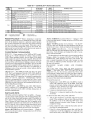
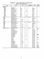
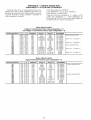
GENERAL
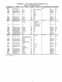
This publication contains Start-Up, Controls, Operation,
Service, and Troubleshooting intbnnation for the 48/50PG
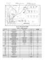
rooftop units. See Table 1. These units are equipped with
('ol_/brtLink TM controls and use Purona)reiiigerant.
Table 1 -- Unit Sizes (48/50PG)
UNIT
NOMINAL
48/50PG20
18
48/50PG24
20
48/50PG28
25
BASIC
TONS
CONTROLUSAGE
ComfortLink
Control -- The Col_/brtLink control is a
colnprehensive unlt-lnanagement system. The control system
is easy to access, configure, diagnose and troubleshoot.
The ComJbrtLink TM control is fully colnmunlcating and
cable-ready for connection to the Carrier Colnfort NetworkS,R)
(CCN) building managelnent system. The control provides
high-speed colnlnunlcations for remote monitoring via the
Intemet. Multiple units can be linked together (and to other
('omJbrtLink control equipped units) using a 3-wire colrnnunication bus.
The ComJbrtLink control system is easy to access through
the use of a unit-lnounted display module. There is no need to
bring a separate computer to this unit tbr start-up. Access to
control menus is simplified by the ability to quickly select fiom
11 menus. A scrolling readout provides detailed explanations
of control int;)nnation. Only tour, large, easy-to-use buttons are
required to maneuver through the entire controls menu. The
display readout is designed to be visible even in bri_lt sunlight.
For added service flexibility, an accessory hand-held
Navigator TM 1nodule is also available. This portable device has
an exteMed colmnunlcation cable that can be plugged into the
unit's colmnunication network at the main control box. The
Navigator display provides the stone menu structure, control
access and display data as is available at the unit-mounted
Scrolling Marquee display.
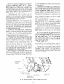
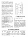
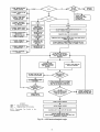
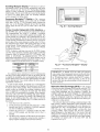
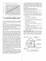
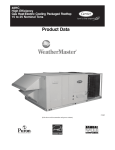
Scrolling Marquee -- This device is the keypad imerface used to access the control information, read sensor values,
and test the unit. The Scrolling Marquee is located in the main
control box and is standard on all units. The Scrolling Marquee
display is a 4-key, 4-character, 16-seglnent LED (light-emitting
diode) display module. The display also contains an Alarm Stares LED. See Fig. 1. The display is easy to operate using 4 buttons and a moup of 11 LEDs that indicate the following menu
structures:
Run Status
Sel_TiceTest
Temperatures
Pressures
Set points
Inputs
Outputs
Configuration
Timeclock
Operating Modes
Alarms
Through the Scrolling Marquee, the user can access all of
the inputs and outputs to check on their values and status, confi_re operating parmneters plus evaluate the current decision
stares for operating modes. The control also includes an alarm
history which can be accessed fioln the display. In addition,
through the Scrolling Marquee, the user can access a built-in
test routine that can be used at start-up comlnissioning and to
dia_ose operational problems with the unit.
Fig. 1 -- Scrolling Marquee
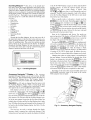
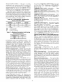
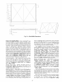
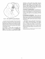
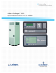
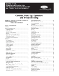
Accessory Navigator TM Display-The accessory
hand-held Navigator display can be used with the 48/50PG
units. See Fig. 2. The Navigator display operates the same way
as the Scrolling Marquee device. The Navigator display is
plugged into the LEN port on either TB2 or the ECB board.
Operation -- All units are shipped tiom the factory with
the Scrolling Marquee display, which is located in the main
control box. See Fig. 1. In addition, the Col_/brtLink TM control
also supports the use of the handheld Navigator display.
Both displays provide the user with an interface to the
ComJbrtLink control system. The displays have [] and []
arrow keys, an _
key and an _
key. These
keys are used to navigate through the different levels of the display structure. The Navigator and the Scrolling Marquee operate in the same manner, except that the Navigator display has
multiple lines of display and the Scrolling Marquee has a single
line. All further discussions and exmnples in this document will
be based on the Scrolling Marquee display. See Table 2 for the
1rlenu
strllcture.
The four keys are used to navigate through the display
structure, ,ahich is organized in a tiered mode structure. If the
buttons have not been used for a period, the display will default
to the AUTO VIEW display category as shown under the RUN
STATUS category. To show the top-level display, press the
key [] until
a keys
blmlkto display
is shown.
Then
and
arrow
scroll through
the top-level
categories. These are listed in Appendix A and will be indicated on the Scrolling Marquee by the LED next to each mode
listed on the face of the display.
When a specific mode or sub-mode is located, push the
key to enter the mode. Depending on the mode, there
may be additional tiers. Cominue to use the [] and [] keys
and the _
keys until the desired display item is found.
At any time, the user can move back a mode level by pressing
the _
key. Once an item has been selected the display
will flash showing the item, followed by the item value and
then t;_llowed by the item units (if any).
Items in the Configuration and Selwice Test modes are
password protected. The display will flash PASS and WORD
,ahen required. Use the _
and arrow keys to enter the
timr digits of the password. The default password is 1111.
Pressing the _
and _
keys simultaneously
will scroll an expanded text description across the display iMicating the full meaning of each display point. Pressing the
and _
keys ,ahen the display is blank
(MODE LED level) will return the display to its delhult menu
of rotating AUTO VIEW display items. In addition, the password will need to be entered again beli_re changes can be made.
ChanNng item values or testing outputs is accomplished in
the stone manner. Locate and display the desired item. If the
display is in rotating auto-vie,a; press the _
key to stop
the display at the desired item. Press the _
key again so
that the item value flashes. Use the arrow keys to change the
value of state of an item and press the _
key to accept
it. Press the _
key and the item, value or units display
wilt resume. Repeat the process as required for other items.
Depending on the unit model, factory-installed options and
field-installed accessories, some of the items in the various
Mode categories may not apply.
Fig. 2 -- Accessory Navigator Display
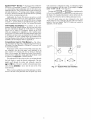
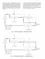
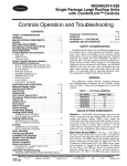
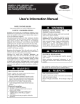
System PilotTM
Device -- The System Pilot (33PILOT01) device is a component of Ca_cier's 3VTM system and serves
as a user-interface and confimlration tool for all Carrier communicating devices. The System Pilot device can be used to install and commission a 3V zoning system, linkage compatible
air source, universal controllei; and all other devices operating
on the Canier comlnunicating network.
Additionally, the System Pilot device can sela_eas a waltmounted temperature sensor for space telnperature measurement. The occupant can use the System Pilot device to change
set points. A security t}amre is provided to limit access of features for unanthorized users. See Fig. 3 for System Pilot details.
value represents a confi_ration setting, an explanation will be
shown in parenthesis after the value. As an example, Configuration--_UNIT--_T.CTL = 1 (1 Stage Y1).
Pressing the _
and _
keys simultaneously
wilt scroll an expanded text description of the point nmne across
the display. The expanded descaiption is sho_s_ in the local display tables but will not be shown with the path nmnes in text.
The CCN point nmnes are also referenced in the local
display tables tbr users configuring the unit with CCN software
instead of the local display. The CCN tables are located in
Appendix A of this manual.
CCN Tables and Display -- In addition to the unitmounted Scrolling Marquee display, the user can also access
the same information through the CCN tables by using the
Service tool or other CCN pro malns. Details on the CCN
tables are smrnnarized in Appendix A. The variable names
used for the CCN tables and the Scrolling Marquee tables may
be different and more items are displayed in the CCN tables.
As a reference, the CCN variable names are included in the
Scrolling Marquee tables and the Scrolling Marquee names are
included in the local display tables in Appendix A.
Conventions
Used in This Manual -- The following conventions for discussing configuration points tbr the local display (Scrolling Marquee or Navigator TM accessory) will
be used in this manual.
Point names wilt be written with the Mode nmne thst, then
any submodes, then the point name, each separated by an
arrow sylnbol (-+). Names will also be shown th bold and
italics. As an example, the Thermostat Control Type which is
located in the Configuration mode, and Unit sub-mode would
be written as (bnfiguration--> UOgTT-->T.CTL.
This path name will show the user how to navigate through
the local display to reach the desired configuration. The user
would scroll through the modes and submodes using the
[] and [] keys. The arrow symbol in the path name represents pressing _
to move into the next level of the
menu structure.
When a value is included as part of the path nmne, it will be
shown at the end of the path name after an equals siN1. If the
S
_MODIFY/
SELECT
NAVIGATE/EXIT
\
/
"1o o
'.,
j
+
SCROLL
\
I_
PAGE
r7
..
Fig. 3 -- System Pilot User Interface
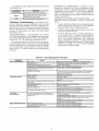
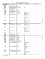
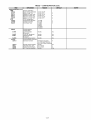
Table 2 -- Scrolling Marquee Menu Display Structure
RUN
STATUS
Auto View of
Run Status
(VIEW)
SERVICE
TEST
Service
Test
TEMPERATURES
Mode
(TEST)
¢
Software
Version
Numbers
(VERS)
¢
Test
¢
Test
¢
¢
Modes
(MODE)
4,
Cooling
Status
(COOL)
¢
Refrigerant
Temperatures
(REFT}
Condenser
Rressu_A
(SCRA)
4,
Occupied
Cool
Setpoint
(OCSR)
4,
Unoccupied
Setpoint
(UCSP)
4,
Cool
Cooling
Suction
Pressure B
(SSRB)
4,
Occupied Heat
Setpoint
(OHSP)
(COOL)
4,
Control
A
INPUTS
Fans
(FANS)
Component
Starts
(STRT)
Temperatures
(AiR.T}
Suction
Pressure
{SSRA)
SETPOINTS
4,
Testlndependent
Outputs
(iNDR)
4,
Component
Run Hours
{HRS)
Air
PRESSURES
Test
Humidimizer
(HMZR)
¢
Test Heating
CHEAT)
Condenser
Rressu_B
(SCRB)
4,
Unoccupied
Heat Setpomt
(UHSP)
4,
¢
Economizer
Status
(LOON)
Fan
Outputs
(FANS)
4,
4,
General
Inputs
{GEN I)
4,
Current
Sensor
Inputs
(CS IN}
4,
Air Quality
Inputs
{AIR Q)
CONFIGURATION
Display
Configuration
(DISP)
4,
CooJ Outputs
{COOL)
4,
Heat Outputs
(HEAT)
4,
Economizer
Outputs
(LOON)
4,
Alarm
Relay
(ALRM)
Unit
Configuration
(UNIT)
4,
Cooling
Configuration
(COOL)
4,
TIME
CLOCK
Time of Day
(TIME)
4,
Month
Date
Day andYear
(DATE)
4,
Daylight
Savings
Time
{DST)
OPERATING
MODES
Control
Modes
{MODE)
4,
Cool
Diagnostic
(COOL)
4,
Humidimizer
{HMZR)
4,
4,
Heat
Humidimizer
Config.
(HMZR}
4,
LocalTime
Schedule
(SCHL)
4,
C
(SSRC)
4,
Condenser
Pressure
C
(SCRC)
Heat-Cool
Setpoint
(GAP)
Heating
Configuration
(HEAT)
SPT Offset
Range
{±)
(STO R)
Economizer
Configuration
(ECON)
4,
4,
4,
Space RH
Setpoint
(RH SP)
Air Quality
Cfg.
(AIR.Q)
Space RH
Deadband
{RH.DB)
Alarm Relay
Conflg.
(ALM O)
4,
4,
Reheat
Heat
SP Deadband
{RH.HB)
4,
Sensor
Calibration
(TRIM)
4,
CEcuRA
Lockout Temp
(CA.LO}
4,
Circuit B
Lockout Temp
(CBLO)
4,
Circuit C
Lockout Temp
{CC LO)
Heating
Lockout Temp
(HTLO)
Econo Cool Hi
Temp Limit
(EH.LO}
4,
Econo CoolLo
Temp Limit
(ELLO)
4,
Free Cool Low
Temp Limit
{FC LO)
Low Cool SAT
Set Point
{LCSR)
4"
High Cool SAT
Set Point
(HCSP)
4,
Minimum SAT
Upper Level
{SAT.U)
Minimum
SAT
Lower
Level
(SA'ZL)
CCN
Configuration
(CON)
Local
Holiday
Schedules
(HOL.L)
ALARMS
ResetAII
Current
Alarms
(R CURR)
4,
Mode
Mode
Diagnostic
(HEAT)
4,
Economizer
Suction
Pressure
4,
Heating
Status
(HEAT)
Thermostat
Inputs
{STAT)
OUTPUTS
Diagnostic
{LOON)
Reset
Alarm
History
(RHIST)
4,
Currently
Active
Alarms
{CURR)
4,
Alarm
History
(HIST)
START-UP
various motor pulley settings. To alter tan performance, see
Evaporator Fan Performance Adjustment section on page 87.
Use the t'ollowing information and Start-Up Checklist on
page CL-1 to check out unit PRIOR to start-up.
Unit Preparation
-- Check that unit Ms been installed in
accor&mce with these installation instructions and all applicable codes.
Compressor
MountingCompressors are internally
spring mounted. Do not loosen or remove compressor holddown bolts.
Refrigerant
Service Ports -- Each independent reft-igerant system has a total of 3 Schrader-type service gage
ports per circuit. One port is located on the suction line, one on
the compressor dischaNe line, and one on the liquid line. Be
sure that caps on the ports are ti_lt.
Crankcase
Craalkcase heaters are energized as long as there is power to the unit and the compressor is
not operating.
Compressor
Return-Air
Filters -- Check that correct filters are installed in filter tracks (see Physical Data table in Installation
Instructions). Do not operate unit without return-air filters.
NOTE: For units with 4-in. filter option, units are shipped with
standard 2-in. filters. To install 4-in. filters, the filter spacers
must be removed.
Outdoor-Air Inlet Screens --Outdoor-air
must be in place before operating unit.
Heater(s)-
IMPORTANT: Unit power must be on for 24 hours prior
to start-up. Otherwise, damage to compressor may
result.
Condenser
Fans and Motors -- Condenser thns and
motors are factory set. Refer to Condenser-Fan Adjustment
section (page 88) as required.
I
I
Rotation
hnproper wiring wilt cause compressor stoppage and alarm.
Correct wiring by switching leads as indicated below.
It is important to be certain the compressors are rotating in
the proper direction. To determine whether or not compressors
are rotating in the proper direction, use a phase-rotation meter
on the unit input power to check tbr L1-L2-L3 or cloclcwise rotation or use the Service Test mode to energize a compressor. If
the compressor is rotating in the wrong direction, the controls
will stop the compressor and display alarm for "Circuit x Failure to Pressurize," where x is the corresponding A or B compressor circuit.
NOTE: Indoor or outdoor thn rotation direction may not indicate proper input power phase sequence, as some 3-phase units
use single-phase tan motors.
To correct the wrong compressor rotation direction, perform
the following procedure:
1. Turn offpower to the unit and lock out the power.
2. Switch any two of the incoming unit power leads.
3. Turn on power to the unit.
4. Verii_ corrected compressor rotation.
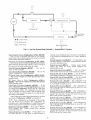
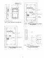
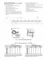
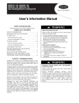
Gas Heat (48PG Only) -- Veril_ gas pressures before
turning on heat as follows:
1. Turn off field-supplied manual gas stop, located external
to unit.
2. Connect pressure gage to supply gas tap, located on fieldsupplied manual shutoffvalve (see Fig. 4).
3. Connect pressure gage to manifold pressure tap.
4. Turn on field-supplied manual gas stop. Enter Service
Test mode by setting TEST to "YES" using the Scrolling
Marquee display. Temporarily install the jumper wire
between "R" and "WI" on TB2. Use the Sin:ice Test
feature to set HT. 1 to ON (first stage of hea 0 using the
Scrolling Marquee.
5. After the unit has mn for several minutes, veri_ the supply gas press_ureis between 5.5 in. wg to 13.0 in. wg, and
the manitbld pressure is 2.95 in. wg on horizontal discharge applications and 3.00 on vertical dischaige applications. If manifold pressure must be adjusted, refer to
Gas _alve Adjustment section.
NOTE: Supply gas pressure must not exceed 13.0 in. wg.
6. Set HT. 1to OFF using Scrolling Marquee.
7. Remove jumper wire if the unit will be operating under
thermostat mode. The jumper must remain if a space temperature sensor (T-55, T-56, or T-58) wilt control the unit.
8. Exit Service Test mode by setting TEST to "NO" using
the Scrolling Marquee.
MANUALSHUTOFF
(FIELD SUP_
GAS
PRESSURE TAP
(1/8" NPT PLUG)
Internal Wiring--Check
all electrical connections in
unit control boxes; tighten as required.
Subcooler
Heat Exchanger
(SHX) -- The subcooler heat exchanger adds approximately 10 to 15° F of subcooling to the system. Check all valves aald TXM
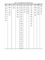
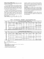
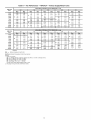
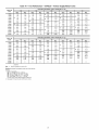
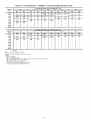
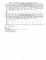
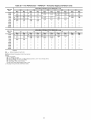
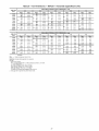
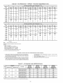
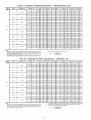
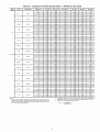
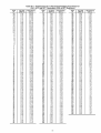
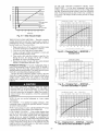
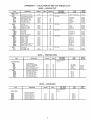
Evaporator
FanFan belt and variable pulleys are
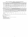
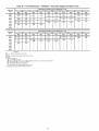
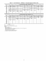
factory-installed. See Tables 3-26 for tan performance data. Be
sure that fans rotate in the proper direction. See Tables 27 and
28 for air quantity limits. See Tables 29 and 30 for evaporator
tan motor specifications. See Tables 31 and 32 for accessory
FIOP static pressure. See Tables 33 and 34 for tan rpm at
inlet screens
Fig. 4--
Field Gas Piping
connected to a 208-v power supply, the transformers (TRAN 1,
TRAN2 and TRAN3) must be rewired by moving the wire
fiom the 230-volt connection and moving to the 200-volt
terminal on the primary side of the transibnner. Rei}r to unit
label dia_am for additional inforlnation.
Orifice Change (48PG Only) -- This unit is factory
assembled for heating operation using natural gas at aal elevation lfom sea level to 2000 ft.
Use accessory high altitude kit when installing this unit at
an elevation of 2000 to 7000 ft. For elevations above 7000 ft,
refer to High Altitude section on page 90 to identit) the correct
orifice size for the elevation. Purchase
these orifices
Air Baffles -- The 48/50PG units with Humid-MiZer TM
option are equipped with Motonnastera) control to maintain
adequate discha_e pressure for proper unit operation during
low mnbient operation. Field-fabricated and installed wind bat'ties may be required. See Optional Humidi-MiZer Dehmnidification System section on page 45.
from your
local Carrier dealei_ Follow instructions in accessory Installation Instructions to install the correct orifices.
Use accessory LP (liquid propane) gas conversion kit when
converting this unit for use with LP fuel usage for elevations
up to 7000 ft. For elevations above 7000 ft, ret_r to High
Altitude section on page 90 to identit) the correct orifice size
for the elevation. Purchase these orifices fiom your local
Carrier dealer. Follow instructions in accessory Installation
Instructions to install the correct orifices.
Accessory Installation -- Check to make sure that all
accessories including space thermostats and sensors have
been installed and wired as required by the instructions and
unit wiring diagrams.
Power Supply -- All 208/230-v units are factory
wired for 230-v power supply. If the 208/230-v unit is to be
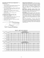
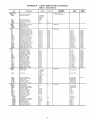
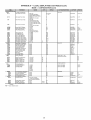
Table 3 -- Fan Performance -- 48PGD020 -- Vertical Supply/Return
AVAILABLE
AIRFLOW
(Cfm)
0.2
EXTERNAL
0.4
Bhp
1.47
Rpm
5000
Rpm
590
5500
6000
633
677
1.82
2.21
703
6500
722
2.67
7000
767
7500
Rpm
0.8
Bhp
1.0
Rpm
Bhp
Rpm
840
Bhp
872
294
727
201
786
2.26
764
240
820
2.67
803
284
857
3.13
907
342
942
3.95
453
A
252
744
211
253
786
301
842
333
894
3.64
3.17
828
353
883
388
933
4.21
813
3.74
871
412
924
4.48
972
4.83
979
1017
8000
859
4.36
915
966
515
1012
5.52
1056
588
8500
906
5.05
B
959
4.77
547
1008
587
1053
6.26
664
9000
952
5.81
C
1004
625
1051
667
1095
7.07
1096
1136
Rpm
1032
Bhp
3.52
Rpm
1076
Bhp
377
1057
401
1099
427
1084
455
1125
483
1114
514
1153
544
579
1183
610
1215
682
A
A
5000
5500
1.2
A
A
B
B
B
C
AVAILABLE
AIRFLOW
(Cfm)
C
EXTERNAL
1.4
STATIC PRESSURE
C
1.8
Bhp
277
Rpm
940
Bhp
3.02
Rpm
987
3.27
Bhp
747
(in. wg)
1.6
Rpm
891
518
2.0
921
321
968
3.48
1014
3.74
6000
954
370
999
3.99
1042
4.27
6500
988
425
1032
4.55
1073
4.85
1024
485
1066
5.17
1106
5.48
7500
1060
551
1101
5.84
1140
6.17
1145
1178
8000
1098
623
1138
6.58
1176
6.92
1213
726
1249
760
1137
1176
701
786
1175
1214
7.38
8.24
1212
1250
7.74
1248
1285
809
899
1283
1319
845
9.36
7000
8500
9000
B
C
B
C
D
B
C
D
LEGEND
Bhp
(in. wg)
0.6
Bhp
1.74
663
STATIC PRESSURE
Units
--
Brake Horsepower
Input to Fan
Boldface indicates field-supplied motor/drive required
NOTES:
1 Motor drive ranges:
(A) Low Range: 685-939,426
Bhp (208/230 and 460-v), 751-954,575
(B) Mid-Low Range: 949-1206, 5.75 Bhp
(C) Mid High Range: 941-1176, 863 Bhp
(D) High Range: 1014-1297, 1150 Bhp
Att other rpms require field-supplied motor or drive
2 See page 30 for general fan performance notes.
Bhp (575-v)
8.61
B
C
D
650
B
D
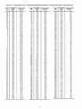
Table 4 -- Fan Performance
-- 48PGE20 -- Vertical Supply/Return
AVAILABLE
AIRFLOW
EXTERNAL
0.4
0.2
(Cfm)
1,53
Rpm
677
Bhp
1.80
Rpm
Bhp
5000
607
Rpm
740
Bhp
206
779
247
819
293
wg)
0.8
1.0
Rpm
797
Bhp
231
833
274
872
322
Rpm
850
Bhp
257
884
301
921
350
958
405
998
466
5500
652
1.90
719
219
6000
699
2.32
763
263
6500
746
2.79
8O7
312
861
344
911
375
7000
794
3.33
851
368
904
402
952
434
7500
842
3.93
897
4.30
947
4.65
994
500
1038
533
8000
891
4.59
943
4.98
991
535
1036
571
1079
607
8500
940
5.32
B
990
572
1036
611
1080
649
1121
687
9000
990
6.12
C
1037
654
1082
695
1124
735
1163
773
Bhp
Bhp
356
Rpm
1083
1108
4.33
A
B
C
AVAILABLE
AIRFLOW
(Cfm)
1.2
EXTERNAL
1.4
A
B
C
STATIC PRESSURE
C
1.8
2.0
5000
900
5500
933
3.27
979
354
1023
380
6000
967
3.79
B 1011
407
B 1054
435
1095
462
1135
4.90
6500
1003
4.35
1046
465
1087
494
1127
524
1165
5.53
1041
4.98
1082
529
1122
560
1160
591
1197
6.22
7500
1079
5.67
1119
599
C 1158
632
1195
664
D 1231
6.96
8000
1119
6.42
1158
676
1195
710
1231
744
1267
7.78
1160
7.23
1198
759
D 1234
795
1269
830
1303
8.65
D 1202
8.12
1238
849
1273
887
1308
9.23
1341
9.60
7000
8500
9000
B
C
C
D
Bhp
B
(in. wg)
1.6
Rpm
949
A
Bhp
2.82
Rpm
Bhp
306
Rpm
995
331
Rpm
1040
1066
406
LEGEND
Bhp
STATIC PRESSURE(in.
0.6
Units
--
BrakeHorsepowerlnputtoFan
Boldface indicates fieId-supplied motor/drive required.
NOTES:
1. Motor drive ranges:
(A) Low Range: 685-939, 4.26 Bhp (208/230 and 460-v), 751-954,575
(B) Mid-Low Range: 949-1206, 575 Bhp
(C) Mid High Range: 941-1176, 8.63 Bhp
(D) High Range: 1014-1297, 11.50 Bhp
All other rpms require field-supplied motor or drive.
2. See page 30 for general fan performance notes
Bhp (575-v)
B
C
D
B
381
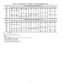
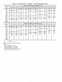
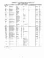
Table 5 -- Fan Performance
--48PGF20
AVAILABLE
AIRFLOW
(Cfm)
0.2
Rpm
EXTERNAL
0.4
Supply/Return
STATIC PRESSURE
(in. wg)
0.8
0.6
Rpm
677
Bhp
1.80
Units
1.0
5000
607
Bhp
1.53
5500
652
1.90
719
2.19
6000
699
232
763
6500
746
279
807
2.63
3.12
7000
794
333
851
3.68
904
4.02
7500
842
393
897
4.30
947
4.65
8000
891
4.59
943
4.98
991
5.35
1036
5.71
8500
940
5.32
B
990
5.72
1036
6.11
1080
649
99O
612
C
1037
6.54
1082
6.95
1124
735
1163
9000
c
A
Bhp
231
833
274
872
322
3.44
911
375
952
994
434
5.00
Bhp
740
2.06
779
2.47
819
2.93
861
B
C
EXTERNAL
1.4
1.2
Rpm
797
Rpm
A
A
AVAILABLE
AIRFLOW
(Cfm)
B
C
STATIC PRESSURE
A
B
C
Rpm
850
Bhp
257
884
301
921
350
958
405
998
466
1038
533
1079
607
1121
687
773
(in. wg)
1.6
1.8
2.0
Rpm
995
Bhp
3.31
Rpm
1040
Bhp
356
Rpm
1083
Bhp
949
Bhp
3.06
979
3.54
1023
3.80
1066
406
1108
433
1011
4.07
1054
4.35
1095
462
1135
490
435
1046
4.65
1087
4.94
1127
524
1165
553
1041
498
1082
5.29
1122
5.60
1160
591
1197
622
7500
1079
567
1119
5.99
1158
6.32
1195
664
1231
696
8000
1119
642
1158
6.76
1195
1231
744
1267
778
1160
723
1198
1269
830
1303
8.65
1202
812
7.59
8.49
7.10
7.95
1308
9.23
1341
9.60
Rpm
Bhp
Rpm
900
282
933
327
6000
967
379
6500
1003
5000
5500
7000
A
B
C
8500
9000
D
B
C
D
1238
B
C
D
1234
1273
LEGEND
Bhp
--Vertical
--
Brake Horsepower
Input to Fan
Boldface indicates field-supplied motor/drive required
NOTES:
1 Motor drive ranges:
(A) Low Range: 685-939,426
Bhp (208/230 and 460-v), 751-954,575
(B) Mid-Low Range: 949-1206, 5.75 Bhp
(C) Mid High Range: 941-1176, 863 Bhp
(D) High Range: 1014-1297, 1150 Bhp
All other rpms require field-supplied motor or drive
2 See page 30 for general fan performance notes.
Bhp (575-v)
8.87
B
C
D
B
D
381
Table 6 -- Fan Performance -- 48PGD24 -- Vertical Supply/Return
AVAILABLE
AIRFLOW
(Cfm)
EXTERNAL
0.4
0.2
Rpm
7O3
Bhp
211
Rprn
764
Bhp
240
744
253
8O3
284
786
301
842
333
3.17
828
353
883
388
813
3.74
871
412
924
4.48
8,000
859
4.36
915
4.77
966
515
8,500
906
5.05
959
547
1008
587
9,000
962
5.81
1004
625
1051
667
9,500
999
6.63
1049
709
1094
753
10,000
1047
7.53
1094
800
1138
846
5,500
Rpm
633
Bhp
1.82
6,000
677
2.21
6,500
722
2.67
7,000
767
7,500
A
B
C
AVAILABLE
AIRFLOW
(Cfm)
B
C
EXTERNAL
1.4
1.2
Rpm
921
Bhp
3.21
Rpm
968
Bhp
6,000
954
3.70
6,500
988
4.25
1024
7,500
8,000
A
B
C
D
STATIC PRESSURE
1.6
348
Rpm
1014
Bhp
374
999
399
1042
B
1032
455
1073
427
485
4.85
1066
517
1106
C
1060
5.51
1101
584
1140
548
617
1098
6.23
658
1176
692
7.01
1212
774
9,000
1137
1176
1138
1175
7.86
1214
824
1250
9,500
1216
8.77
917
1256
9.75
1253
1292
1016
5,500
7,000
8,500
10,000
A
B
C
D
B
C
D
c
738
D
--
(in. wg)
0.8
1.0
Rpm
82O
Bhp
267
857
313
894
364
933
421
972
483
1012
552
1053
626
1095
707
1137
795
1180
890
A
B
C
D
Rpm
872
Bhp
294
9O7
342
942
3.95
979
453
1017
518
1056
586
1096
664
1136
747
1177
836
1219
933
(in. wg)
1.8
2.0
Rpm
1057
Bhp
1084
1114
455
Rpm
1099
401
Bhp
4.27
1125
4.83
514
1153
5.44
1145
1178
579
1183
6.10
650
1215
6.82
1213
726
1249
7.60
1248
809
1283
8.45
861
1285
899
1319
9.36
1288
956
1322
9.95
1355
10.33
1327
10.57
1360
10.98
1393
11.38
LEGEND
Bhp
STATIC PRESSURE
0.6
Units
BrakeHorsepowerlnputtoFan
Boldface indicates field-supplied motor/drive required.
NOTES:
1. Motor drive ranges:
(A) Low Range: 685-939, 4.26 Bhp (208/230 and 460-v), 751-954, 575 Bhp (575-v)
(B) Mid-Low Range: 949-1206, 575 Bhp
(C) Mid High Range: 941-1176, 8.63 Bhp
(D) High Range: 1014-1297, 11.50 Bhp
All other rpms require field-supplied motor or drive.
2. See page 30 for general fan performance notes
10
D
B
D
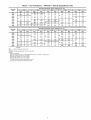
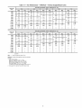
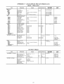
Table 7 -- Fan Performance -- 48PGE24 -- Vertical Supply/Return
AVAILABLE
AIRFLOW
(Cfm)
0.2
Rpm
EXTERNAL
0.4
5,500
652
Bhp
1.90
6,000
699
232
6,500
746
279
7,000
794
7,500
Rpm
(in. wg)
0.6
0.8
719
763
2.63
819
2.93
872
322
807
3.12
861
3.44
911
375
333
851
3.68
904
4.02
952
434
842
393
897
4.30
947
4.65
994
5.00
1038
533
8,000
891
4.59
943
4.98
991
5.35
1036
5.71
1079
607
8,500
940
532
990
5.72
1036
6.11
1080
6.49
1121
687
9,000
990
612
1037
6.54
1082
6.95
1124
7.35
1163
773
9,500
1039
700
1085
7.43
1128
7.85
1168
8.27
1207
867
10,000
1089
795
1133
8.40
1174
8.83
1213
9.26
1251
969
Rpm
1066
Bhp
406
Rpm
1108
Bhp
433
1095
462
1135
490
1127
524
1165
553
1160
591
1197
622
1195
664
1231
696
1231
744
1267
778
8.65
A
B
C
AVAILABLE
5,500
1.2
A
Rpm
933
A
B
C
D
Rpm
779
Bhp
2.47
1.0
Bhp
2.19
AIRFLOW
(Cfm)
EXTERNAL
1.4
Bhp
3.27
B
C
D
STATIC PRESSURE
Bhp
274
979
1011
4.07
1046
4.65
435
1087
494
1122
560
1158
632
1195
710
1234
795
1269
830
1303
1273
887
1308
9.23
1341
9.60
1379
10.62
7,000
1041
4.98
1082
5.29
7,500
1079
5.67
1119
5.99
8,000
1119
6.42
1158
6.76
8,500
1160
7.23
1198
9,000
1202
8.12
1238
7.59
8.49
1244
9.07
1279
9.46
1314
9.85
1347
10.24
1287
10.10
1321
10.61
1355
10.91
1387
11.31
10,000
C
D
D
D
LEGEND
--
Brake HorsepowerlnputtoFan
Boldface indicates field-supplied motor/drive required
NOTES:
1 Motor drive ranges:
(A) Low Range: 685-939,426
Bhp (208/230 and 460-v), 751-954,
(B) Mid-Low Range: 949-1206, 5.75 Bhp
(C) Mid High Range: 941-1176, 863 Bhp
(D) High Range: 1014-1297, 1150 Bhp
AIr other rpms require fieId-supplied motor or drive
2 See page 30 for general fan performance notes.
466
1054
3.79
C
405
998
2.0
4.35
C
D
350
958
1.8
967
B
C
921
Bhp
380
1003
B
B
Bhp
301
Rpm
1023
6,000
B
A
Rprn
884
(in. wg)
1.6
Bhp
3.54
Rpm
A
Rpm
833
6,500
9,500
Bhp
STATIC PRESSURE
Units
575 Bhp (575-v)
11
B
C
D
B
D
Table 8 -- Fan Performance -- 48PGF24 -- Vertical Supply/Return
AVAILABLE
AIRFLOW
(Cfm)
0.2
EXTERNAL
0.4
Rpm
719
Bhp
219
Rprn
763
263
819
807
312
861
293
344
3.33
851
368
904
402
842
3.93
897
4.30
947
8,000
891
4.59
943
4.98
991
4.65
535
8,500
940
6.32
990
572
1036
611
9,000
990
6.12
1037
654
1082
695
9,500
1039
7.00
1085
743
1128
785
10,000
1089
7.95
1133
840
1174
883
5,500
Rpm
652
Bhp
1.90
6,000
699
2.32
6,500
746
2.79
7,000
794
7,500
A
B
C
AVAILABLE
AIRFLOW
(Cfm)
5,500
A
B
C
D
EXTERNAL
1.4
1.2
Rpm
933
779
Bhp
327
Rpm
979
Bhp
1011
407
1046
465
354
Bhp
247
A
B
Bhp
380
1054
1087
435
494
1122
560
1158
632
1195
1234
710
795
0.8
C
D
1.0
Rpm
833
Bhp
274
872
322
911
375
952
434
500
994
1036
A
B
571
1080
STATIC PRESSURE
1.6
Rpm
1023
(in. wg)
1124
649
735
1168
827
1213
926
C
D
Rpm
884
Bhp
301
921
350
958
405
998
1038
466
1079
607
1121
1163
687
1207
867
1251
969
533
773
(in. wg)
1.8
2.0
Rpm
1066
Bhp
406
Rpm
1108
Bhp
4.33
B
1095
1127
462
524
1135
1165
4.90
C
1160
591
1197
1195
664
744
6.22
1231
1267
6.96
830
1303
8.65
6,000
967
379
6,500
1003
435
7,000
1041
498
1082
529
7,500
1079
567
1119
599
8,000
1119
642
1158
676
8,500
1160
723
1198
759
9,000
1202
812
849
1273
887
1308
9.23
1341
9.60
1244
907
1238
1279
946
1314
9.85
1347
10.24
1379
10.62
1287
1010
1321
10.51
1355
10.91
1387
11.31
9,500
10,000
B
C
D
B
C
D
B
C
D
LEGEND
Bhp
STATIC PRESSURE
0.6
Units
--
BrakeHorsepowerlnputtoFan
Boldface indicates field-supplied motor/drive required.
NOTES:
1. Motor drive ranges:
(A) Low Range: 685-939, 4.26 Bhp (208/230 and 460-v), 751-954, 575 Bhp (575-v)
(B) Mid-Low Range: 949-1206, 575 Bhp
(C) Mid High Range: 941-1176, 8.63 Bhp
(D) High Range: 1014-1297, 11.50 Bhp
All other rpms require field-supplied motor or drive.
2. See page 30 for general fan performance notes
12
D
1231
1269
B
D
5.53
7.78
Table 9 -- Fan Performance
-- 48PGD28 -- Vertical Supply/Return
AVAILABLE
AIRFLOW
(Cfm)
0.2
Rprn
6,500
750
Bhp
2.84
797
3.38
7,500
845
3.99
8,000
892
4.65
8,500
939
5.38
9,000
986
6.17
1033
10,000
10,500
Rprn
A
A
0.8
Rpm
854
Bhp
349
899
409
945
476
Bhp
379
941
985
Rprn
943
Bhp
412
441
982
474
509
1024
543
1030
586
1067
620
1076
669
1112
705
1122
760
1157
798
1203
899
1249
1008
B
3.77
4.42
948
5.13
991
551
995
5.91
1038
632
1042
6.76
1085
721
7.03
1090
7.69
1132
817
1169
859
1079
7.95
1137
8.68
1180
921
1216
966
1126
8.94
1184
9.75
1227
1033
1263
1081
1296
11 25
1172
10.00
1232
10.90
1274
11.52
1310
12.04
1342
12.51
11,500
1219
11.13
1279
12,12
1322
12.80
1357
13.35
12,000
1265
12.34
1326
13.42
12,500
1311
13.63
11,000
B
C
D
B
C
D
AVAILABLE
AIRFLOW
(Cfm)
1.2
Bhp
4.49
Bhp
4.89
7,000
1024
5.09
7,500
1063
5.78
1066
5.48
1101
6.15
8,000
1104
6.55
1140
8,500
1146
7.41
9,000
1190
8.35
9,500
1235
9.37
10,000
1280
10,500
1326
11,000
1372
12.95
C
D
EXTERNAL
D
(in. wg)
1109
590
1141
656
6.92
1176
732
1180
7.78
1214
817
1222
1255
1266
8.73
9.76
10.48
1310
11.67
1355
2.0
Rpm
1177
Bhp
632
1197
685
1222
746
774
1251
819
1249
858
1283
9.01
911
1287
952
1319
9.94
1296
1015
1327
10.55
1357
10.97
10.88
1340
11.28
1369
11.68
1398
12.10
12.08
1384
12.49
C
D
11,500
12,000
12,500
LEGEND
--
C
1.8
Bhp
533
D
D
STATIC PRESSURE
Rpm
1082
C
C
1.6
Rpm
1035
B
C
1.4
Rpm
988
6,500
B
B
1.0
Rpm
898
900
9,500
Bhp
(in. wg)
0.6
Bhp
3.18
806
STATIC PRESSURE
853
7,000
A
EXTERNAL
0.4
Units
Brake HorsepowerlnputtoFan
Boldface indicates field-suppfled motor/drive required
NOTES:
1 Motor drive ranges:
(A) Low Range: 687-873,575
Bhp
(B) Mid-Low Range: 805-1007, 5.75 Bhp
(C) Mid High Range: 941-1176, 863 Bhp
(D) High Range: 1014-1297, 1150 Bhp
AIr other rpms require fieId-supplied motor or drive
2 See page 30 for general fan performance notes.
]3
C
D
Rpm
1130
Bhp
581
1153
635
1181
699
1213
D
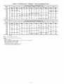
Table 10 -- Fan Performance
-- 48PGE28 -- Vertical Supply/Return
AVAILABLE
AIRFLOW
(Cfm)
6,500
0.2
A
Rpm
775
EXTERNAL
0.4
Bhp
299
826
358
878
424
8,000
929
8,500
A
Rpm
825
Bhp
330
Rpm
A
STATIC PRESSURE
0.6
423
966
494
1015
572
1052
606
1064
658
1114
751
1100
1148
1198
893
1247
498
975
537
981
578
1026
620
1033
667
1076
712
9,500
1085
764
1128
812
1164
854
10,000
1137
869
1179
920
1214
964
10,500
1190
982
1230
1037
1265
1084
11,000
1242
1105
1282
11.63
1316
12.12
11,500
1294
12.37
1333
12.98
1367
13.50
12,000
1347
13.78
9,000
C
B
C
B
C
D
1.0
918
392
461
B
0.8
Rpm
871
925
7,500
(in. wg)
Bhp
360
875
7,000
B
C
D
Units
915
Bhp
391
959
455
1005
526
Rpm
959
Bhp
4.25
1000
4.88
1043
5.60
1088
6.40
693
1134
7.28
789
1181
8.25
B
C
D
1229
9.31
1005
1278
10.45
1297
1127
1327
11.68
1347
12.58
1376
13.01
Rpm
1145
Bhp
597
Rpm
1192
Bhp
6.49
1170
654
1214
7.04
1199
720
1240
7.68
797
1270
8.43
884
1304
9.28
12,500
AVAILABLE
AIRFLOW
(Cfm)
1.2
Rpm
1004
Bhp
462
7,000
1041
524
7,500
1081
596
8,000
1124
8,500
9,000
6,500
B
C
D
EXTERNAL
1.4
Rpm
1050
Bhp
1083
564
1120
634
676
1160
713
1168
764
1202
802
1214
862
1245
C
D
(in. wg)
1.8
2.0
Rpm
1098
Bhp
548
1126
607
1159
675
1196
754
1235
842
1233
1269
900
1277
939
1309
9.81
1341
10.24
1381
11.31
503
C
D
C
D
9,500
1260
969
1290
1007
1320
10.47
1351
10.88
10,000
1308
10.84
1337
11.23
1365
11.63
1394
12.05
10,500
1356
12.09
1384
12.49
11,000
11,500
12,000
12,500
LEGEND
Bhp
STATIC PRESSURE
1.6
--
B_keHorsepowerlnputtoFan
Boldface indicates field-supplied motor/drive required.
NOTES:
1. Motor drive ranges:
(A) Low Range: 687-873, 5.75 Bhp
(B) Mid-Low Range: 805-1007, 575 Bhp
(C) Mid High Range: 941-1176, 8.63 Bhp
(D) High Range: 1014-1297, 11.50 Bhp
All other rpms require field-supplied motor or drive.
2. See page 30 for general fan performance notes
14
D
Table 11 -- Fan Performance
-- 48PGF28 --Vertical
AVAILABLE
AIRFLOW
(Cfm)
0.2
Rprn
6,500
Bhp
2.99
775
A
7,000
826
3.58
7,500
878
929
4.24
4.98
8,500
981
5.78
9,000
1033
9,500
1085
6.67
7.64
10,000
1137
8.69
10,500
1190
9.82
11,000
1242
11,500
12,000
8,000
EXTERNAL
0.4
A
Rpm
825
STATIC PRESSURE
Bhp
3.30
A
0.8
Rpm
871
Bhp
360
918
966
423
494
1015
572
1064
1114
658
751
3.92
925
975
4.61
1026
6.20
1076
1128
7.12
8.12
1164
854
1179
9.20
1230
10.37
1214
1265
964
1084
11.05
1282
11.63
1316
12.12
1294
12.37
1333
12.98
1367
13.50
1347
13.78
B
C
D
B
5.37
C
D
Units
(in. wg)
0.6
875
B
Supply/Return
B
C
D
1.0
Rpm
915
Bhp
391
959
455
1005
526
1052
1100
606
693
1148
789
1198
893
1247
B
C
D
Rpm
959
Bhp
425
1000
488
1043
560
1088
1134
640
1181
825
728
1229
931
1005
1278
1045
1297
1127
1327
11.68
1347
12.68
1376
13.01
Rpm
1145
Bhp
597
Rpm
1192
Bhp
649
1170
654
1214
704
1199
720
1240
768
1233
797
1270
843
12,500
AVAILABLE
AIRFLOW
(Cfm)
1.2
Rpm
1004
Bhp
4.62
7,000
1041
5.24
7,500
1081
5.96
8,000
1124
8,500
9,000
6,500
B
C
EXTERNAL
1.4
Bhp
5.03
1083
1120
5.64
6.34
6.76
1160
7.13
1168
7.64
1202
1214
8.02
9.00
C
D
1126
1159
607
1196
754
1235
1277
842
1269
884
1304
9.28
939
1309
9.81
1341
10.24
1381
11.31
548
C
675
D
1260
10.07
1320
10.47
1351
10.88
1308
10.84
1337
11.23
1365
11.63
1394
12.05
10,500
1356
12.09
1384
12.49
11,000
11,500
12,000
12,500
LEGEND
Bhp
2.0
Bhp
10,000
D
1245
1290
1.8
Rpm
1098
8.62
9.69
9,500
D
(in. wg)
1.6
Rpm
1050
C
STATIC PRESSURE
--
Brake HorsepowerlnputtoFan
Boldface indicates field-suppfled motor/drive required
NOTES:
1 Motor drive ranges:
(A) Low Range: 687-873,575
Bhp
(B) Mid-Low Range: 805-1007, 5.75 Bhp
(C) Mid High Range: 941-1176, 863 Bhp
(D) High Range: 1014-1297, 1150 Bhp
AIr other rpms require fieId-supplied motor or drive
2 See page 30 for general fan performance notes.
15
D
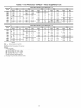
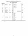
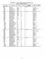
Table 12 -- Fan Performance
-- 50PG20 --Vertical
AVAILABLE
AIRFLOW
(Cfm)
0.2
Rpm
EXTERNAL
STATIC PRESSURE
0.6
(in. wg)
Rpm
682
Bhp
1.82
0.4
5000
533
Bhp
1.27
5500
571
6000
610
6500
Rpm
Rpm
611
Bhp
1.54
1.57
643
1.86
711
215
1.92
676
2.21
74O
252
650
2.31
712
261
772
7000
691
275
748
308
7500
732
324
788
8000
775
379
8500
817
9000
860
773
244
8OO
282
293
829
8O5
339
357
839
824
412
4.40
863
4.74
5.06
904
5.41
Rprn
Bhp
302
918
938
883
358
859
373
911
407
391
891
425
941
4.61
874
4.47
924
4.83
972
519
911
5.09
B
958
546
1003
584
948
577
C
993
615
1036
654
Bhp
Bhp
344
Rpm
1065
1081
416
1099
465
EXTERNAL
910
344
6500
935
390
7000
961
(in. wg)
1.8
2.0
988
359
1035
387
960
374
1008
405
1054
435
422
474
1030
454
1075
486
1118
518
440
984
1008
1054
508
1098
541
1140
575
989
496
1035
531
1079
566
1122
601
1163
636
1018
556
1062
593
1105
629
1147
666
1187
702
1048
622
1091
660
1133
698
1173
736
1212
773
1079
693
1121
732
1161
771
1201
811
1239
850
886
6000
--
C
317
A
B
C
LEGEND
Bhp
STATIC PRESSURE
1.6
B
969
5500
9000
313
325
291
331
264
C
273
857
A
Rpm
1018
865
8500
832
A
Bhp
5000
8000
Bhp
237
Rpm
Bhp
B
C
Rpm
8O8
1.4
1.2
Rpm
7500
1.0
748
A
Units
0.8
Bhp
210
AVAILABLE
AIRFLOW
(Cfm)
Supply/Return
Brake Horsepower
input to Fan
Boldface indicates fieId-supplied drive required.
NOTES:
1. Motor drive ranges:
(A) Low Range: 685-939, 4.26 Bhp (208/230 and 460-v), 751-954,
575 Bhp 4 (575-v)
(B) Mid-Low Range: 949-1206, 575 Bhp
(C) Mid-High Range: 941-1176, 863 Bhp
(D) High Range: 1014-1297, 11.50 Bhp
All other rpms require field-supplied drive.
2. See page 30 for general fan performance notes
16
B
C
D
B
C
D
370
Table 13-
Fan PerformanceAVAILABLE
AIRFLOW
(Cfm)
0.2
50PG24EXTERNAL
0.4
5,500
Rpm
571
Bhp
1,57
6,000
610
6,500
650
7,000
Rpm
STATIC PRESSURE
0.6
643
Bhp
1.86
Rpm
711
Bhp
2.15
1.92
676
2.21
74O
2.52
2.31
712
2.61
772
2.93
691
2.75
748
3.06
8O5
7,500
732
3.24
786
3.57
8,000
775
3.79
824
4.12
8,500
817
4.40
863
9,000
860
5.06
9,500
903
10,000
947
(in. wg)
0.8
1.0
Bhp
2.44
8O0
2.82
3.25
883
3.58
3.39
829
859
3.73
911
4.07
839
3.91
891
4.25
941
4.61
874
4.47
924
4.83
972
519
4.74
911
5.09
958
5.46
1003
584
904
5.41
948
5.77
993
6.15
1036
6.54
5.79
944
6.14
986
6.51
6.90
1070
7.29
6.57
985
6.93
1025
7.32
1028
1065
7.71
1105
8.11
1035
Bhp
3.87
Rpm
1081
4.16
1099
4.65
1118
5.18
1140
5.75
6.36
EXTERNAL
1.4
1.2
5,500
Units
Rpm
773
AVAILABLE
AIRFLOW
(Cfm)
Rpm
886
Bhp
3.02
A
Rpm
938
A
B
C
STATIC PRESSURE
1.6
Bhp
3.31
Rpm
988
Bhp
3.59
A
B
C
Rpm
832
Bhp
2.73
857
3.13
(in. wg)
1.8
Rpm
2.0
Bhp
910
3.44
960
3.74
1008
4.05
1054
4.35
6,500
935
3.90
984
4.22
1030
4.54
1075
4.86
7,000
961
4.40
1008
4.74
1054
5.08
1098
5.41
989
4.96
1035
5.81
1079
5.66
1122
6.01
8,000
1018
5.56
1062
5.93
1105
6.29
1147
6.66
1163
1187
8,500
1048
6.22
1091
6.60
1133
6.98
1173
7.36
1212
7.73
9,000
1079
6.93
1121
7.32
1161
7.71
1201
8.11
8.50
9,500
1112
7.70
1152
8.10
1191
1229
8.91
10,000
1145
8.52
1184
8.94
1222
8.51
9.36
1239
1266
1259
9.78
1295
10.20
6,000
7,500
A
B
C
B
C
D
LEGEND
Bhp
Vertical Supply/Return
--
Brake HorsepowerlnputtoFan
Boldface indicates field-supplied drive required
NOTES:
1 Motor drive ranges:
(A) Low Range: 685-939,426
Bhp (208/230 and 460-v), 751-954,
5.75 Bhp (5.75-v)
(B) Mid-Low Range: 949-1206, 5.75 Bhp
(C) Mid-High Range: 941-1176, 8.63 Bhp
(D) High Range: 1014-1297, 1150 Bhp
AIi other rpms require fieId-sapplied drive
2 See page 30 for general fan performance notes.
17
B
C
D
B
C
D
7.02
9.32
Table 14 -- Fan Performance -- 50PG28 --Vertical
AVAILABLE
AIRFLOW
(Cfm)
0.2
6,500
Rpm
734
Bhp
274
7,000
728
7,500
746
288
315
8,000
786
362
8,500
827
9,000
870
415
474
913
540
987
1002
611
689
11,000
1047
11,500
1092
1137
961
1182
1065
B
9,500
10,000
10,500
C
12,000
D
12,500
Bhp
Rpm
752
A
285
A
803
316
844
370
388
884
429
869
445
925
9O5
504
94O
566
975
630
1010
887
928
430
966
494
564
964
563
1008
604
1046
640
1003
836
1049
683
1086
722
1042
713
1089
768
1127
811
698
1079
794
1128
857
1167
906
1047
772
1115
878
1167
952
1207
1006
773
1086
853
1150
965
1205
1050
1247
1113
863
1126
941
1185
1054
1242
11.53
1286
12,24
1168
1036
1220
11 47
1278
12.59
1325
13,40
1210
1139
1256
12.46
1314
13.68
B
C
D
C
D
EXTERNAL
1.4
7,500
1003
525
8,000
1041
596
440
1007
494
1048
530
1040
557
1078
1076
629
8,500
1081
674
1114
9,000
1121
759
9,500
1161
8 50
C
D
C
D
STATIC PRESSURE
1.6
Bhp
478
B
B
D
1.8
2.0
Bhp
522
1090
570
592
1116
1111
663
707
1147
742
1153
793
1184
828
1193
887
1223
1233
1273
987
1095
D
C
(in. wg)
Rpm
1071
C
B
Bhp
374
1006
461
Rpm
1119
Bhp
1134
615
630
1155
671
1146
699
1181
737
1179
777
1212
814
1215
864
1246
901
923
1253
959
1282
9.96
1263
1025
1291
1062
1319
11.00
1303
11.35
1331
11.73
1358
12.12
1371
12.92
1397
13.32
10,500
1242
948
1053
11,000
1282
11.64
1314
12.09
1343
12.52
11,500
1322
12.81
1354
13.30
1384
13.76
12,500
LEGEND
--
848
Rpm
891
530
12,000
Bhp
A
Bhp
345
968
B
Rpm
1023
1202
Rpm
494
967
D
1.0
0.8
Bhp
335
Bhp
10,000
Rpm
831
Rpm
978
C
wg)
401
463
Bhp
405
B
(in.
Units
927
Rpm
934
7,000
PRESSURE
792
1.2
6,500
STATIC
0.6
AVAILABLE
AIRFLOW
(Cfm)
EXTERNAL
0.4
Supply/Return
B_keHorsepowerlnputtoFan
Boldface indicates field-supplied motor and drive required.
NOTES:
1. Motor drive ranges:
(A) Low Range: 687-873, 5.75 Bhp
(B) Mid-Low Range: 805-1007, 575 Bhp
(C) Mid-High Range: 941-1176, 863 Bhp
(D) High Range: 1014-1297, 11.50 Bhp
All other rpms require field-supplied motor/drive
2. See page 30 for general fan performance notes
18
C
D
C
D
571
Table 15 -- Fan Performance -- 48PGD20 -- Horizontal Supply and Return Units
AVAILABLE
AIRFLOW
(Cfm)
0.2
Rpm
5000
5500
862
Bhp
2.55
937
326
6000
1013
358
6500
1089
4.48
1166
552
1243
671
8000
1320
807
8500
1398
9.60
F
7000
G
7500
H
EXTERNAL
0.4
Rpm
Bhp
2.93
917
F
G
H
988
1060
3.56
1133
4.89
1207
5.96
1282
7.18
1356
8.57
F
3.96
G
H
STATIC PRESSURE
0.6
Rpm
969
Bhp
3.21
1036
3.53
1105
4.35
1175
5.31
1247
6.41
1319
7.66
1392
9.08
(in. wg)
0.8
1.0
Rpm
1019
Bhp
3.17
1083
3.90
1149
4.75
G
1216
5.73
H
1285
6.86
1355
F
Rpm
1066
Bhp
352
1127
4 28
1191
516
1256
617
1323
732
8.14
1391
8.63
Bhp
502
G
Rpm
1280
Bhp
542
H
1331
630
1384
7.31
F
G
H
9000
AVAILABLE
AIRFLOW
(Cfm)
1.2
Rpm
5000
F
5500
6000
6500
7000
G
H
1112
1171
EXTERNAL
1.4
Bhp
388
467
1232
557
1295
661
1360
7.80
F
G
H
Rpm
1156
Bhp
4.25
1212
5.06
1271
6.00
1333
7.06
1396
8.27
G
H
STATIC PRESSURE
1.6
G
Rpm
1240
1253
5.47
H
1292
588
1310
6.43
1348
6.87
1369
7.52
8500
9000
LEGEND
Brake Horsepower
Input to Fan
Boldface indicates field-supplied motor/drive required
NOTES:
1 Motor drive ranges:
(E) Low Range: Not Used
(F) Mid-Low Range: 896-1227, 4.26 Bhp (208/230 and 460-v), 873-1108,575
(G) Mid-High Range: 1113-1414, 5.75 Bhp
(H) High Range: 1096-1339, 8.63 Bhp
All other rpms require field-supplied motor or drive
2 See page 30 for general fan performance notes.
2.0
Bhp
4.63
8000
--
1.8
Rpm
1199
7500
Bhp
(in. wg)
Bhp (575-v)
19
Table 16 -- Fan Performance
-- 48PGE20 -- Horizontal Supply and Return Units
AVAILABLE
AIRFLOW
0.2
(Cfm)
5000
5500
6000
F
6500
Rpm
875
Bhp
2.74
962
3.38
1029
3.74
1106
4.67
7000
G
1184
5.75
7500
H
1262
7.00
1341
8.41
8000
EXTERNAL
0.4
Rpm
931
F
G
H
Bhp
304
1003
332
1077
415
1151
511
1226
623
1302
750
1378
8.95
STATIC PRESSURE
0.6
Rpm
F
G
H
984
Bhp
334
1053
370
1123
456
1194
556
1266
1340
(in. wg)
0.8
Rpm
1.0
1035
Bhp
333
1100
409
1167
498
1236
601
671
1306
719
8.01
1377
8.53
F
G
H
F
G
H
Rpm
1083
Bhp
369
1145
4.49
1210
541
1276
647
1344
7.68
8500
9000
m
AVAILABLE
AIRFLOW
(Cfm)
1.2
Rpm
1130
Bhp
4.07
1189
4.90
1251
5.85
6500
1315
6.94
7000
1381
8.18
5000
5500
6000
F
G
H
EXTERNAL
1.4
G
H
Rpm
1174
Bhp
445
1232
531
1292
629
1354
7.41
G
H
STATIC PRESSURE
1.6
Rprn
1218
Bhp
484
1273
572
1331
674
1391
7.89
7500
8000
8500
9000
LEGEND
Bhp
--
BrakeHorsepowerlnputtoFan
Boldface indicates fieId-supplied motor/drive required.
NOTES:
1. Motor drive ranges:
(E) Low Range: Not Used
(F) Mid-Low Range: 896-1227, 426 Bhp (208/230 and 460-v),
(G) Mid-High Range: 1113-1414, 5.75 Bhp
(H) High Range: 1096-1339, 863 Bhp
All other rpms require field-supplied motor or drive.
2. See page 30 for general fan performance notes
873-1108, 575 Bhp (575-v)
2O
(in. wg)
1.8
2.0
G
Rpm
1259
Bhp
523
H
1313
615
1369
7.19
G
Rpm
1300
Bhp
1352
6.58
5.63
Table 17 -- Fan Performance -- 48PGF20 -- Horizontal Supply and Return Units
AVAILABLE
AIRFLOW
(Cfm)
0.2
Rpm
5000
5500
875
Bhp
2.74
952
338
6000
1029
374
6500
1106
4.67
F
Rpm
F
G
931
Bhp
3.04
1003
3.32
1077
4.15
1151
5.11
1226
6.23
G
1184
575
7500
H
1262
700
1302
7.50
1341
8.41
1378
8.95
H
STATIC PRESSURE
(in. wg)
0.6
7000
8000
EXTERNAL
0.4
F
G
H
1.0
0.8
Rpm
984
1035
Bhp
333
3.34
1053
3.70
1123
4.56
1100
409
1167
498
1194
5.56
1236
601
1266
6.71
1306
719
1340
8.01
1377
8.53
Bhp
Rpm
F
G
H
F
G
H
Rpm
1083
Bhp
369
1145
449
1210
541
1276
647
1344
7.68
8500
9000
AVAILABLE
AIRFLOW
(Cfm)
5000
5500
6000
6500
7000
1.2
F
G
H
Rpm
1130
EXTERNAL
1.4
Bhp
407
1189
490
1251
585
1315
694
1381
8.18
Rpm
1174
G
1232
4.45
5.31
1292
6.29
H
1354
7.41
G
H
Bhp
STATIC PRESSURE
1.6
Rpm
Bhp
1218
1273
4.84
5.72
1331
6.74
1391
7.89
1.8
2.0
Rpm
Bhp
G
1259
523
H
1313
1369
Rpm
Bhp
1300
563
615
1352
6.58
7.19
m
G
m
m
7500
m
8000
m
8500
m
9000
m
LEGEND
Bhp
(in. wg)
--
Brake Horsepower
Input to Fan
Boldface indicates field-supplied motor/drive required
NOTES:
1 Motor drive ranges:
(E) Low Range: Not Used
(F) Mid-Low Range: 896-1227, 4.26 Bhp (208/230 and 460-v), 873-1108,575
(G) Mid-High Range: 1113-1414, 5.75 Bhp
(H) High Range: 1096-1339, 8.63 Bhp
All other rpms require field-supplied motor or drive
2 See page 30 for general fan performance notes.
Bhp (575-v)
21
Table 18 -- Fan Performance -- 48PGD24 -- Horizontal Supply and Return Units
AVAILABLE
AIRFLOW
(Cfm)
0.2
Rpm
937
Bhp
3.26
6,000
1013
3.58
6,500
1089
4.49
1166
5.52
1243
6.71
8,000
1320
8.07
8,500
1398
9.60
5,500
F
7,000
G
7,500
H
EXTERNAL
0.4
F
G
H
Rpm
988
Bhp
356
STATIC PRESSURE
0.6
Rprn
F
1036
Bhp
353
1105
4.35
1175
531
1247
641
1060
396
1133
489
1207
596
1282
718
1319
766
1366
8.57
1392
9.08
G
H
(in. wg)
0.8
Rpm
F
G
H
1.0
1083
Bhp
390
1149
475
1216
573
1285
686
1366
8.14
1391
Rpm
1292
Bhp
588
Rpm
1331
Bhp
630
1348
6.87
1384
7.31
G
H
Rpm
1127
Bhp
428
1191
516
1256
617
1323
732
8.63
9,000
9,500
10,000
m
AVAILABLE
AIRFLOW
(Cfm)
5,500
1.2
G
6,000
6,500
7,000
H
EXTERNAL
1.4
Rpm
1171
Bhp
4.67
1232
5.57
1295
6.61
1360
7.80
G
H
Rpm
1212
Bhp
506
1271
600
1333
706
1396
8.27
STATIC PRESSURE
1.6
G
Rpm
1253
Bhp
547
H
1310
643
1369
7.52
7,500
8,000
8,500
9,000
9,500
10,000
LEGEND
Bhp
--
Brake Horsepower
input to Fan
Boldface indicates field-supplied motor/drive required.
NOTES:
1. Motor drive ranges:
(E) Low Range: Not Used
(F) Mid-Low Range: 896-1227, 426 Bhp (208/230 and 460-v),
(G) Mid-High Range: 1113-1414, 5.75 Bhp
(H) High Range: 1096-1339, 863 Bhp
All other rpms require field-supplied motor or drive.
2. See page 30 for general fan performance notes
873-1108, 575 Bhp (575-v)
22
H
(in. wg)
1.8
2.0
H
Table 19 -- Fan Performance -- 48PGE24 -- Horizontal Supply and Return Units
AVAILABLE
AIRFLOW
(Cfm)
0.2
Rpm
952
Bhp
338
6,000
1029
374
6,500
1106
4.67
5,500
F
EXTERNAL
0.4
7,000
G
1184
575
7,500
H 1262
700
8,000
1341
8.41
Rpm
F
G
H
1003
Bhp
3.32
1077
4.15
1151
5.11
1226
8.23
1302
7.50
1378
8.95
F
G
H
STATIC PRESSURE
0.6
Rpm
1053
Bhp
3.70
1123
4.56
1194
5.56
1266
1340
(in. wg)
0.8
1.0
F
Rpm
1100
Bhp
4.09
G
1167
4.98
1236
8.01
6.71
1306
7.19
8.01
1377
8.53
H
G
H
Rpm
1145
Bhp
449
1210
541
1276
647
1344
7.68
8,500
9,000
9,500
10,000
m
AVAILABLE
AIRFLOW
(Cfm)
1.2
Bhp
490
Rpm
1232
Bhp
5.31
1251
585
1292
8.29
6,500
1315
694
1354
7.41
7,000
1381
8.18
6,000
G
H
STATIC PRESSURE
G
5.72
H
1331
6.74
1391
7.89
8,000
8,500
9,000
9,500
10,000
LEGEND
--
Brake Horsepower
1.8
Rpm
1273
7,500
Bhp
(in. wg)
1.6
Rpm
1189
5,500
EXTERNAL
1.4
Input to Fan
Boldface indicates field-supplied motor/drive required
NOTES:
1 Motor drive ranges:
(E) Low Range: Not Used
(F) Mid-Low Range: 896-1227, 4.26 Bhp (208/230 and 460-v), 873-1108,575
(G) Mid-High Range: 1113-1414, 5.75 Bhp
(H) High Range: 1096-1339, 8.63 Bhp
AIr other rpms require fieId-supplied motor or drive
2 See page 30 for general fan performance notes.
Bhp (575-v)
23
Bhp
H
2.0
Rpm
1313
Bhp
8.15
1369
7.19
Rpm
Bhp
1352
6.58
Table 20 -- Fan Performance
-- 48PGF24 -- Horizontal Supply and Return Units
AVAILABLE
AIRFLOW
0.2
(Cfm)
5,500
F
Rpm
952
Bhp
3.38
6,000
1029
3.74
6,500
1106
4.67
7,000
G
1184
5.75
7,500
H
1262
7.00
1341
8.41
8,000
EXTERNAL
0.4
F
G
H
Rpm
1003
Bhp
332
1077
415
1151
511
1226
623
1302
750
1378
8.95
F
G
H
STATIC PRESSURE
0.6
Rpm
1053
Bhp
370
1123
456
1194
556
1266
1340
F
G
(in. wg)
0.8
Rprn
1100
1.0
Bhp
409
Bhp
449
1210
541
1276
647
1344
7.68
G
1167
498
1236
601
671
1306
719
8.01
1377
8.53
H
1145
Rpm
H
8,500
9,000
9,500
10,000
AVAILABLE
AIRFLOW
(Cfm)
1.2
Rpm
1189
Bhp
4.90
1251
5.85
6,500
1315
6.94
7,000
1381
8.18
5,500
6,000
G
H
EXTERNAL
1.4
G
H
Rpm
1232
Bhp
531
1292
629
1354
7.41
STATIC PRESSURE
1.6
G
Rpm
1273
Bhp
572
H
1331
674
1391
7.89
7,500
8,000
8,500
9,000
9,500
10,000
LEGEND
Bhp
--
Brake Horsepower
input to Fan
Boldface indicates field-supplied motor/drive required.
NOTES:
1. Motor drive ranges:
(E) Low Range: Not Used
(F) Mid-Low Range: 896-1227, 426 Bhp (208/230 and 460-v),
(G) Mid-High Range: 1113-1414, 5.75 Bhp
(H) High Range: 1096-1339, 863 Bhp
All other rpms require field-supplied motor or drive.
2. See page 30 for general fan performance notes
873-1108, 575 Bhp (575-v)
24
(in. wg)
1.8
Rpm
H
1313
1369
2.0
Bhp
615
7.19
Rprn
1352
Bhp
6.58
Table 21 -- Fan Performance -- 48PGD28 -- Horizontal Supply and Return Units
AVAILABLE
AIRFLOW
(Cfm)
0.2
Rprn
6,500
Bhp
3.06
786
E
7,000
842
3.69
7,500
898
4.40
955
5.20
1012
6.08
1069
8,000
F
8,500
9,000
E
F
871
925
979
4.61
5.40
1034
6.29
1090
1146
7.26
8.32
1202
9.49
1258
10.75
9,500
1127
10,000
1184
9.27
1242
10.52
11,000
1299
11,88
1315
12.11
11,500
1357
13.35
1372
13.58
H
G
Bhp
3.26
3.89
Rpm
819
H
STATIC PRESSURE
(in. wg)
0.6
7.05
8.11
10,500
G
EXTERNAL
0.4
Rpm
E 857
905
F
414
485
955
1007
H
F
585
1059
G
0.8
Bhp
351
853
750
1113
1167
G
857
H
1.0
Rpm
943
Bhp
412
442
983
474
513
1026
544
1037
592
1070
623
1087
680
1117
710
1138
777
1165
807
1190
884
1215
913
1243
1000
1266
1029
Rpm
899
Bhp
380
943
989
F
G
H
1221
973
1276
1099
1296
1126
1318
11.55
1332
12.36
1350
12.63
1370
12.92
Rpm
1129
Bhp
581
Rpm
1177
Bhp
1153
635
1197
684
1221
1250
746
902
12,000
12,500
AVAILABLE
AIRFLOW
(Cfm)
6,500
1.2
F
Rpm
988
Bhp
4.49
7,000
1024
5.09
7,500
1063
5.79
8,000
1105
8,500
Rpm
1035
Bhp
4.89
5.48
1102
8.16
8.57
1140
1149
7.44
9,000
1194
8.40
9,500
H 1242
10,000
10,500
11,000
Rpm
1082
1.8
Bhp
533
G
2.0
632
589
1141
656
1181
8.93
1176
732
1213
699
774
1181
7.79
1215
818
1249
858
1283
1225
8.75
1256
913
1287
953
1319
9.95
9.48
1270
9.80
1298
10.17
1328
10.57
1358
10.98
1290
10.61
1316
10.96
1343
11.32
1370
11.71
1399
12.12
1340
11.87
1364
12.21
1389
12.57
1391
13.23
G
H
G
H
12,000
12,500
LEGEND
--
(in. wg)
1109
11,500
Bhp
STATIC PRESSURE
1.6
1066
G
EXTERNAL
1.4
Brake HorsepowerlnputtoFan
Boldface indicates field-suppfled motor/drive required
NOTES:
1 Motor drive ranges:
(E) Low Range: 687-873,575
Bhp
(F) Mid-Low Range: 805-1007, 5.75 Bhp
(G) Mid-High Range: 941-1176, 8.63 Bhp
(H) High Range: 1014-1297, 1150 Bhp
AIr other rpms require fieId-supplied motor or drive
2 See page 30 for general fan performance notes.
25
H
H
818
Table 22 -- Fan Performance -- 48PGE28 -- Horizontal Supply and Return Units
AVAILABLE
AIRFLOW
0.2
(Cfm)
6,500
Rpm
799
E
EXTERNAL
0.4
Bhp
314
E
Rpm
833
887
Bhp
335
400
F
941
474
Rpm
E
STATIC PRESSURE
0.6
921
425
972
499
1024
580
1055
608
1078
671
1132
771
1106
1158
1187
880
1211
908
1243
1000
1265
856
379
913
452
971
533
996
555
1029
624
1052
1087
723
9,500
1145
832
1108
1165
646
746
10,000
1203
950
1222
974
10,500
1261
1079
1279
1103
1299
11.28
11,OOO
1320
12.18
1337
12.43
1355
12.70
11,500
1378
13.68
F
8,500
9,000
G
G
H
G
855
H
1.0
872
7,500
8,000
0.8
Rpm
Bhp
361
7,000
F
(in. wg)
F
G
H
914
Bhp
390
958
454
1006
527
F
Rpm
958
Bhp
4.24
999
4.87
1042
5.59
1088
6.40
699
1136
7.30
799
1185
8.29
G
H
1236
9.39
1028
1288
10.58
1319
11.58
1341
11,88
1374
12.98
1394
13.28
Rpm
1148
Bhp
600
Rpm
1195
Bhp
6.52
1217
7.08
1242
7.71
8.45
12,000
12,500
AVAILABLE
AIRFLOW
(Cfm)
1.2
Rpm
1005
Bhp
462
Rpm
1052
Bhp
7,000
1041
524
7,500
1080
594
1084
564
1119
633
8,000
1122
674
1158
712
8,500
1167
763
1200
800
9,000
1214
863
1244
6,500
F
G
EXTERNAL
1.4
G
H
(in. wg)
1.8
2.0
Rpm
1100
Bhp
551
1128
609
1172
657
1160
676
1201
722
1195
753
797
1272
1234
840
1233
1269
883
1304
8.29
899
1275
937
1308
9.79
1340
10,23
1379
11.28
505
G
H
G
H
9,500
1262
972
1290
1007
1319
10.45
1349
10.85
10,000
1312
10.91
1338
11.25
1365
11.63
1392
12.02
10,500
1363
12.20
1387
12.55
11,000
11,500
12,000
12,500
LEGEND
Bhp
STATIC PRESSURE
1.6
--
B_keHorsepowerlnputtoFan
Boldface indicates field-supplied motor/drive required.
NOTES:
1. Motor drive ranges:
(E) Low Range: 687-873, 5.75 Bhp
(F) Mid-Low Range: 805-1007, 575 Bhp
(G) Mid-High Range: 941-1176, 863 Bhp
(H) High Range: 1014-1297, 11.50 Bhp
All other rpms require field-supplied motor or drive.
2. See page 30 for general fan performance notes
26
H
Table 23 -- Fan Performance -- 48PGF28 -- Horizontal Supply and Return Units
AVAILABLE
AIRFLOW
(Cfm)
0.2
Rprn
6,500
E
Bhp
3.14
799
Rpm
E
833
Bhp
3.35
887
4.00
941
4.74
3.79
913
4.52
8,000
971
5.33
996
5.55
8,500
1029
8.24
1052
8.46
1087
7.23
1108
7.46
9,500
1145
8.32
1165
8.55
10,000
1203
9.50
1222
9.74
10,500
1261
10.79
1279
11.03
11,000
1320
12.18
1337
12.43
11,500
1378
13.68
7,500
9,000
F
G
H
F
G
H
STATIC PRESSURE
(in. wg)
0.6
856
7,000
EXTERNAL
0.4
E
F
G
H
0.8
Rpm
872
Bhp
361
921
972
425
499
1024
580
1078
671
1132
771
1187
880
1243
1.0
Rpm
914
Bhp
390
958
454
1006
527
1055
1106
608
699
1158
799
1211
908
1000
1265
1299
11.29
1355
12.70
F
G
H
F
G
H
Rprn
958
Bhp
424
999
487
1042
559
1088
640
1136
7 30
1185
829
1236
939
1028
1288
1058
1319
11.58
1341
11.88
1374
12.98
1394
13.28
Rpm
1148
Bhp
600
Rpm
1195
Bhp
652
12,000
12,500
AVAILABLE
AIRFLOW
(Cfm)
1.2
Rpm
1005
Bhp
4.62
1041
5.24
1080
5.94
8,000
1122
8,500
9,000
6,500
F
7,000
7,500
G
EXTERNAL
1.4
Bhp
5.05
1084
5.64
1119
6.33
6.74
1158
7.12
1167
7.63
1200
1214
8.63
1244
8.00
8.99
H
H
G
H
1.8
2.0
Rpm
1100
Bhp
551
1128
609
1172
657
1217
708
1160
676
1201
722
1242
771
1195
1234
753
848
1233
797
1272
845
1269
883
1304
9.29
1275
937
1308
9.79
1340
10.23
1379
11.28
G
H
9,500
1262
9.72
1290
10.07
1319
10.45
1349
10.85
10,000
1312
10.91
1338
11.25
1365
11.63
1392
12.02
10,500
1363
12.20
1387
12.55
11,000
11,500
12,000
12,500
LEGEND
Bhp
(in. wg)
1.6
Rpm
1052
G
STATIC PRESSURE
--
Brake Horsepower
Input to Fan
Boldface indicates field-supplied motor/drive required
NOTES:
1 Motor drive ranges:
(E) Low Range: 687-873,575
Bhp
(F) Mid-Low Range: 805-1007, 5.75 Bhp
(G) Mid-High Range: 941-1176, 8.63 Bhp
(H) High Range: 1014-1297, 1150 Bhp
Atl other rpms require field-supplied motor or drive
2 See page 30 for general fan performance notes.
27
H
Table 24 -- Fan Performance -- 50PG20 -- Horizontal Supply/Return
AVAILABLE
AIRFLOW
(Cfm)
0.2
EXTERNAL
0.4
Rpm
642
Bhp
1.61
Rpm
7OO
Bhp
184
0.8
1.0
5000
5500
619
1.71
682
1.96
737
221
6000
663
2.09
723
235
776
262
6500
708
253
765
280
816
308
863
335
9O6
3.63
7000
753
302
8O7
330
857
359
9O2
388
944
4.17
7500
800
358
85O
386
898
416
942
4.47
8000
847
420
894
4.48
940
4.60
982
511
8500
894
4,88
939
5.17
982
549
1024
582
941
563
983
592
1025
624
1065
G
Bhp
1,37
(in. wg)
Rpm
575
9000
G
AVAILABLE
AIRFLOW
(Cfm)
EXTERNAL
1.4
1.2
Bhp
289
Rpm
972
1103
6.92
G
(in. wg)
1.8
2.0
1096
4.61
1114
5.10
1100
534
1139
5.66
1131
598
1167
6.29
1165
667
1199
6.99
1200
743
1232
7.76
1237
826
1268
8.59
1005
419
1032
398
448
7000
984
446
1023
475
1062
504
7500
1021
507
1059
537
1095
567
8000
1059
574
1095
605
1130
636
1099
647
1133
679
1167
711
1138
726
1172
759
1205
793
28
6.14
658
478
369
990
BrakeHorsepowerlnputtoFan
5.43
1062
429
960
390
--
4.77
1073
341
949
Boldface indicates fieId-supplied drive required.
NOTES:
1. Motor drive ranges:
(E) Low Range: 685-939, 4.26 Bhp (208/230 and 460-v), 751-954,
575 Bhp (575-v)
(F) Mid-Low Range: 949-1206, 575 Bhp
(G) Mid-High Range: 941-1176 863 Bhp
(H) High Range: 1014-1297, 11.50 Bhp
All other rpms require field-supplied drive.
2. See page 30 for general fan performance notes
982
1022
F
1050
916
6500
LEGEND
3.14
4.21
6000
H
2.71
871
1086
355
9000
837
387
985
G
E
1035
325
G
288
Bhp
935
8500
245
825
Bhp
2.33
Rpm
1084
297
F
788
Rpm
8O8
Bhp
353
886
E
G
Bhp
208
Rpm
1028
260
5500
F
Rpm
754
Bhp
320
862
5000
Bhp
E
STATIC PRESSURE
1.6
Rpm
917
Rpm
Bhp
STATIC PRESSURE
0.6
Units
F
G
H
F
G
H
3.89
Table 25 -- Fan Performance -- 50PG24 -- Horizontal Supply/Return
AVAILABLE
AIRFLOW
(Cfm)
0.2
EXTERNAL
0.4
Bhp
1.71
Rpm
5,500
Rpm
619
6,000
663
6,500
7O8
7,000
682
Bhp
1.96
Rpm
737
Bhp
2.21
2.09
723
2.35
776
2.62
2.53
765
2.80
816
3.08
753
3.02
807
3.30
857
7,500
8OO
3.58
850
3.86
8,000
847
4.20
894
4.48
8,500
894
4.88
939
5.17
9,000
941
5.63
983
5.92
9,500
989
6.45
1029
6.74
10,000
1037
7.34
1075
7.63
AVAILABLE
AIRFLOW
(Cfm)
4.17
942
4.47
982
4.77
940
4.80
982
5.49
982
5.11
1022
5.43
1024
5.82
1062
1025
6.24
1065
6.58
6.14
1103
1069
7.07
1108
6.92
7.41
1144
1113
7.96
1150
7.77
8.32
H 1186
8.68
990
4.19
1032
4.48
4.46
1023
4.75
1062
1021
5.07
1059
5.37
1059
5.74
1095
6.05
1099
6.47
1133
1138
7.26
1179
8.12
1220
9.04
7,000
Bhp
1050
4.29
1096
4.61
1073
4.78
1114
5.10
5.04
1100
5.34
1139
5.66
1095
5.67
1131
5.98
G
6.29
1130
6.36
1165
6.67
1167
1199
6.79
1167
7.11
1200
7.43
H
7.76
1172
7.59
1205
1237
8.26
1212
8.46
1244
7.93
8.81
1232
1268
1275
9.15
1305
9.50
1252
9.40
1283
9.76
1313
10.11
1342
10.47
949
3.90
984
7,500
8,000
F
G
H
2.0
1.8
3.98
6,500
G
(in. wg)
1005
E
E
F
3.63
1035
3.41
G
H
LEGEND
--
944
3.69
916
10,000
4.16
STATIC PRESSURE
1.6
3.88
960
6,000
H
898
EXTERNAL
9O2
E
Rpm
1086
935
9,500
3.59
G
871
9O6
3.14
3.35
3.25
2.97
9,000
2.88
863
F
Bhp
2.71
Bhp
3.87
Bhp
G
825
E
Rpm
837
Rpm
886
1.0
Bhp
2.45
Bhp
3.55
Rpm
8,500
G
0.8
Rpm
985
Bhp
F
F
(in. wg)
Rpm
788
1.4
1.2
Rpm
5,500
Bhp
STATIC PRESSURE
0.6
Units
Brake HorsepowerlnputtoFan
Boldface indicates field-supplied drive required
NOTES:
1 Motor drive ranges:
(E) Low Range: 685-939,426
Bhp (208/230 and 460-v), 751-954,
5.75 Bhp (575-v)
(F) Mid-Low Range: 949-1206, 5.75 Bhp
(G) Mid-High Range: 941-1176, 8.63 Bhp
(H) High Range: 1014-1297, 1150 Bhp
AIr other rpms require fieId-supplied motor or drive
2 See page 30 for general fan performance notes.
29
F
G
H
F
4.21
6.99
8.59
Table 26 -- Fan Performance -- 50PG28 -- Horizontal Supply/Return
AVAILABLE
AIRFLOW
(Cfm)
0.2
Rpm
759
6,500
EXTERNAL
0.4
Bhp
Rpm
8O4
Bhp
317
853
377
903
443
953
STATIC PRESSURE
0.6
Rpm
844
Bhp
342
891
404
939
472
518
988
548
1003
599
1037
1054
689
1087
632
723
1137
E
Units
(in. wg)
0.8
1.0
Rpm
Rpm
883
Bhp
368
928
430
922
964
974
500
1008
529
1021
577
1053
607
1069
1118
662
1100
693
755
1147
787
822
1167
856
1195
889
1187
930
1216
966
1243
1001
E
F
913
412
484
8,500
965
563
9,000
1017
650
1069
745
1105
786
1121
848
1156
892
1173
960
1207
1006
1238
1047
1266
1085
1292
1121
11,000
1226
1081
1259
1130
1288
11.72
1316
12.12
1342
12.50
11,500
1278
12.11
1310
12.62
1339
13.07
1366
13.49
12,000
1331
13.51
E
7,000
810
862
7,500
8,000
F
G
9,500
10,000
10,500
H
G
H
F
G
H
F
G
H
F
Bhp
396
289
347
G
H
458
12,500
AVAILABLE
AIRFLOW
(Cfm)
1.2
Rpm
962
Bhp
427
Rpm
1003
Bhp
461
7,000
1000
7,500
1041
488
1037
521
558
1075
590
1085
637
1116
8,500
1129
723
9,000
1175
818
9,500
1222
922
10,000
1270
10,500
1318
11,000
1366
6,500
8,000
F
G
H
EXTERNAL
1.4
STATIC PRESSURE
1.6
1115
1145
595
661
1180
736
1219
822
883
1260
918
1288
953
1276
988
1302
10.22
1329
10.58
1068
1321
11.02
1346
11.37
1371
11.72
11.90
1367
12.25
1391
12.61
13.22
--
--
1075
1110
556
624
668
1148
701
1159
755
1189
788
1204
850
1232
1249
955
1034
1296
11.56
1343
12.86
1390
H
2.0
Bhp
541
Bhp
498
G
1.8
Rpm
1090
Rpm
1045
F
(in. wg)
G
H
G
H
G
H
Rpm
1135
Bhp
587
1155
638
1182
701
1214
774
1249
859
11,500
12,000
12,500
LEGEND
Bhp
--
BrakeHorsepowerlnputtoFan
Boldface indicates field-supplied motor/drive required.
NOTES:
1. Motor drive ranges:
(E) Low Range: 687-873, 5.75 Bhp
(F) Mid-Low Range: 805-1007, 5,75 Bhp
(G) Mid-High Range: 941-1176, 863 Bhp
(H) High Range: 1014-1297, 11.50 Bhp
All other rpms require field-supplied motor or drive.
2. See betow for general fan performance notes.
GENERAL
1
2
NOTES
FOR FAN PERFORMANCE
Static pressure losses from accessories and options (HumidFMiZer TM,
economizer, etc.) must be added to externaI static pressure before entering Fan Performance table. Refer to Tables 31 and 32 for Accessory/
FlOP Static Pressure information
Extensive motor and electrical testing on these units ensures that the full
range of the motor can be utitized with confidence Using the fan motors
up to the bhp ratings shown wilt not result in nuisance tripping or premature motor faiture. Unit warranty will not be affected See Tables 29 and
DATA TABLES
30 (Evaporator-Fan
Motor Specifications) on page 31 and 32 for additional information.
3. Use of a field-suppIied motor may affect wire sizing. Contact your local
Carrier representative for detaits
4. InterpoIation is permissible. Do not extrapolate
Table 27 -- Air Quantity Limits (48PG20-28 Units)
COOLING
48PG
20
24
28
Minimum Cfm
GASHEAT
Maximum
5000
5500
6500
9,000
10,000
12,000
Cfm
HEATING
(NAT. GAS,
VERTICAL)
MINIMUM CFM
HEATING
(NAT. GAS,
HORIZONTAL)
MINIMUM CFM
HEATING
(PROPANE,
VERTICAL)
MINIMUM CFM
HEATING
(PROPANE,
HORIZONTAL)
MINIMUM CFM
High Heat (8 Cell)
5522
5522
5522
4920
V1edium Heat (8 Cell)
4977
4977
4480
4480
Low Heat (5 Cell)
4218
4218
4218
3796
High Heat (8 Cell)
5522
5522
5522
4920
4977
4977
4480
4480
Low Heat (5 Cell)
4218
4218
4218
3796
High Heat (8 Cell)
5522
5470*
5522
4920*
4977
4977*
4480
4480*
4218
4218
4218
3796
_edium
_edium
Heat (8 Cell)
Heat (8 Cell)
Low Heat (5 Cell)
*7000 cfm minimum recommended
above 1 0 in wg external static pressure.
3O
Table 28 -- Air Quantity Limits (50PG20-28 Units)
ELECTRIC HEAT
(Vertical)
MINIMUM CFM
ELECTRIC HEAT
(Horizontal)
MINIMUM CFM
4,500
5.400
3,756
4.800
Low Heat (25 kW)
3,750
3.750
High Heat (75 kW)
4,560
5.400
3,756
4.800
Low Heat (25 kW)
3,750
3.750
High Heat (75 kW)
4,560
5.400
3,756
4.800
3,750
3.750
COOLING
5OPG
Minimum
Cfm
Maximum
ELECTRIC
Cfm
HEAT
High Heat (75 kW)
20
5000
24
9,000
5500
28
Medium
I0,000
6500
Medium
I2,000
Medium
Heat (50 kW)
Heat (50 kW)
Heat (50 kW)
Low Heat (25 kW)
Table 29 -- Evaporator Fan Motor Specifications -- 48PG20-28 Units
UNIT
46PG
DRIVE
Low
Mid-Low
Mid-High
High
ORIENTATION
Vertical
Vertical
Vertical
Vertical
20
Low
Mid-Low
Mid-High
Horizontal
Horizontal
Horizontal
High
Horizontal
Low
Vertical
Mid-Low
Mid-High
High
Vertical
Vertical
Vertical
24
Low
Mid-Low
Mid-High
High
Horizontal
Horizontal
Horizontal
Horizontal
NOMINAL
VOLTAGE
MAX WATTS
MAX EHP
MAX EkW
MAX AMPS
37
HP
208
3700
858
426
3.17
I0.6
37
230
3700
858
426
3.17
96
37
460
3700
858
426
3.17
48
5
5
575
208
5015
4578
875
875
588
537
4.39
4.01
60
I5.8
5
230
5115
875
600
4.46
I5.4
5
460
5115
875
600
4.46
77
5
575
5015
875
588
4.39
60
75
208
6456
885
766
5.71
22.0
75
230
7169
885
851
6.34
22.0
75
460
7586
885
900
6.71
I1.6
75
575
7586
885
900
6.71
94
10
208
8284
895
994
7.41
28.0
10
230
8708
895
10.45
7.79
28.0
10
460
9330
895
11.19
8.35
I5.0
10
575
9711
895
11.65
8.69
I2.0
N/A
208
N/A
N/A
N/A
N/A
N/A
N/A
230
N/A
N/A
N/A
N/A
N/A
N/A
460
N/A
N/A
N/A
N/A
N/A
N/A
575
N/A
N/A
N/A
N/A
N/A
37
208
3700
858
426
3.17
I0.6
37
230
3700
858
426
3.17
96
37
460
3700
858
426
3.17
48
5
575
5015
875
588
4.39
60
5
208
4578
875
537
4.01
I5.8
5
230
5115
875
600
4.48
I5.4
5
460
5115
875
600
4.48
77
5
575
5015
875
588
4.39
60
75
208
6458
885
766
5.71
22.0
75
230
7169
885
851
6.34
22.0
75
75
460
575
7586
7586
885
885
900
900
6.71
6.71
I1.6
94
37
208
3700
858
426
3.17
I0.6
37
230
3700
858
426
3.17
96
37
460
3700
858
426
3.17
48
5
575
5015
875
588
4.39
60
5
208
4578
875
537
4.01
I5.8
5
230
5115
875
600
4.46
I5.4
5
460
5115
875
600
4.46
77
5
575
5015
875
588
4.39
60
75
208
6458
885
766
5.71
22.0
75
230
7169
885
851
6.34
22.0
75
460
7586
885
900
6.71
I1.6
75
575
7586
885
900
6.71
94
10
208
8284
895
994
7.41
28.0
10
230
8708
895
10.45
7.79
28.0
10
460
9330
895
11.19
8.35
I5.0
10
575
9711
895
11.65
8.69
I2.0
N/A
N/A
208
230
N/A
N/A
N/A
N/A
N/A
N/A
N/A
N/A
N/A
N/A
N/A
460
N/A
N/A
N/A
N/A
N/A
N/A
575
N/A
N/A
N/A
N/A
N/A
37
208
3700
858
426
3.17
I0.6
37
230
3700
858
426
3.17
96
37
460
3700
858
426
3.17
48
5
575
5015
875
588
4.39
60
5
208
4578
875
537
4.01
I5.8
5
230
5115
875
600
4.46
I5.4
5
460
5115
875
600
4.46
77
5
575
5015
875
588
4.39
60
75
208
6458
885
766
5.71
22.0
75
230
7169
885
851
6.34
22.0
75
460
7586
885
900
6.71
I1.6
75
575
7586
885
900
6.71
94
31
EFFICIENCY
%
Table 29 -- Evaporator Fan Motor Specifications -- 48PG20-28 Units (cont)
UNIT
48PG
DRIVE
Low
Mid-Low
Mid-High
High
Low
Mid-Low
Mid-High
High
ORIENTATION
Vertical
Vertical
Vertical
Vertical
Horizontal
Horizontal
Horizontal
Horizontal
NOMINAL
MAX BHP
MAX BkW
MAX AMPS
5
HP
VOLTAGE
2O8
MAX WATTS
4578
87.5
537
4.01
158
5
5
23O
46O
5115
5115
87.5
87.5
6.00
6.00
4.48
4.48
154
77
5
575
5015
87.5
5.88
4.39
5
2O8
4578
87.5
5.37
4.01
158
5
23O
5115
87.5
6.00
4.48
154
5
46O
5115
87.5
6.00
4.48
77
5
575
5015
87.5
5.88
4.39
75
2O8
6458
88.5
766
5.71
220
75
23O
7169
88.5
85I
6.34
220
75
46O
7586
88.5
8.00
6.71
116
75
575
7586
88.5
8.00
6.71
I0
208
8284
89.5
9.94
7.41
280
I0
230
8708
89.5
10.45
7.79
280
I0
460
9330
89.5
1119
8.35
150
I0
575
8711
89.5
1165
8.69
120
5
2O8
4578
87.5
537
4.01
158
5
230
5115
87.5
6.00
4.48
154
5
460
5115
87.5
6.00
4.48
77
5
575
5015
87.5
586
4.39
5
2O8
4578
87.5
537
4.01
158
5
230
5115
87.5
6.00
4.48
154
5
460
5115
87.5
6.00
4.48
77
5
575
5015
87.5
5.88
4.39
75
208
6458
88.5
766
5.71
220
75
230
7169
88.5
85I
6.34
220
75
460
7586
88.5
9.00
6.71
116
75
575
7586
88.5
9.00
6.71
I0
208
8284
89.5
9.94
7.41
280
I0
230
8708
89.5
10.45
7.79
280
I0
460
9330
89.5
1119
8.35
150
I0
575
8711
89.5
1165
8.69
120
NOTES:
1
Extensive motor and efactrical testing ensures that the motors can be uNized with confidence up to the maximum applied bhp, watts, and amps. Using the fan motor up to
the maximum ratings shown wi}l not result in nuisance tripping or premature motor failure. Unit warranty will not be affected
2
All indoor-fan motors 5 hp and larger meet the minimum efficiency requirements
as
established by the Energy Policy Act of 1892 (EPACT) effective October 24, 1997.
Table 30 -- Evaporator
UNIT
5OPG
DRIVE
Low
Mid-Low
Mid-High
High
Low
Mid-Low
Mid-High
High
ORIENTATION
Vertical
Vertical
Vertical
Vertica_
Horizontal
Hobzontal
Horizontal
Horizontal
NOMINAL
HP
3.
watts =
%
bhp to watts using the following
6.0
6.0
8.4
6.0
6.0
8.4
formula:
bhp (746)
motor efficiency
Fan Motor Specifications -- 50PG20-28 Units
MAX BHP
MAX BkW
MAX AMPE
37
VOLTAGE
2O8
MAX WATTS
3700
85.8
4.26
317
10.6
37
23O
3700
85.8
4.26
317
9.6
37
46O
3700
85.8
4.26
317
4.8
5
575
5015
87.5
5.88
439
6.0
5
2O8
4578
87.5
5.37
401
15.8
5
23O
5115
87.5
6.00
448
15.4
5
46O
5115
87.5
6.00
448
7.7
5
575
5015
87.5
5.88
439
6.0
75
2O8
6458
88.5
7.66
571
22.0
75
23O
7169
88.5
8.5I
634
22.0
75
46O
7586
88.5
8.00
671
11.6
75
575
7586
88.5
9.00
671
9.4
I0
208
8284
89.5
9.94
741
26.0
I0
230
8708
89.5
10.45
779
26.0
I0
460
9330
89.5
11.19
835
15.0
I0
575
9711
89.5
11.65
869
12.0
37
208
3700
85.8
4.26
317
10.6
37
230
3700
85.8
4.26
317
9.6
37
460
3700
85.8
4.26
317
4.8
5
575
5015
87.5
5.88
439
6.0
5
2O8
4578
87.5
5.37
401
15.8
5
230
5115
87.5
6.00
448
15.4
5
460
5115
87.5
6.00
448
7.7
5
575
5015
87.5
5.88
439
6.0
75
208
6458
88.5
7.66
571
22.0
75
230
7169
88.5
8.5I
634
22.0
75
460
7586
88.5
9.00
671
11.6
75
575
7586
88.5
9.00
671
9.4
I0
208
8284
89.5
9.94
741
26.0
I0
230
8708
89.5
10.45
779
26.0
I0
460
9330
89.5
11.19
835
15.0
I0
575
9711
89.5
11.65
869
12.0
NOTES:
I.
Convert
EFFICIENCY
2.
Extensive motor and electrical testing ensures that the motors can be utilized with confidence up to the maximum applied bhp, watts, and amps. Using the fan motor up to
the maximum ratings shown will not result in nuisance tripping or premature motor failure Unit warranty will not be affected
3.
%
All indoor-fan motors 5 hp and larger meet the minimum efficiency requirements
established by the Energy Policy Act of 1892 (EPACT) effective October 24. 1997
Convert bhp to watts using the following formula:
watts =
32
EFFICIENCY
bhp (746)
motor efficiency
as
Table 30 -- Evaporator Fan Motor Specifications
UNiT
50PG
DRIVE
Low
Mid-Low
Mid-High
High
ORIENTATION
Vertical
Vertical
Vertical
Vertical
24
Low
Mid-Low
Mid-High
High
Low
Mid-Low
Mid-High
High
Horizontal
Horizontal
Horizontal
Horizontal
Vertical
Vertical
Vertical
Vertical
28
Low
Mid-Low
Mid-High
High
Horizontal
Horizontal
Horizontal
Horizontal
NOMINAL
HP
VOLTAGE
MAX WATTS
MAX BNP
MAX BkW
MAX AMPS
37
208
3700
858
426
3.17
10.6
37
37
230
468
3700
3700
858
858
426
426
3.17
3.17
9.6
4.8
5
575
5015
875
588
4.39
60
5
208
4578
875
537
4.01
158
5
230
5115
875
800
4.48
154
5
468
5115
875
800
4.48
77
5
575
5015
875
588
4.39
75
208
6458
885
766
5.71
220
75
230
7169
885
851
8.34
220
75
468
7586
885
900
8.71
118
75
575
7586
885
900
8.71
10
2O8
8284
895
994
7.41
280
10
23O
8708
89.5
10.45
7.79
280
10
488
9330
89.5
1119
8.35
150
10
575
9711
89.5
1165
8.89
120
37
2O8
3700
858
426
3.17
10.8
37
23O
3700
858
426
3.17
9.8
37
488
3700
858
426
3.17
4.8
5
575
5015
875
588
4.39
5
2O8
4578
875
537
4.01
158
5
23O
5115
875
600
4.48
154
5
488
5115
875
600
4.48
77
5
575
5015
875
588
4.39
60
75
2O8
6458
885
766
5.71
220
75
230
7169
885
851
8.34
220
75
488
7586
885
900
8.71
118
75
575
7586
885
900
8.71
10
2O8
8284
895
994
7.41
280
10
230
8708
89.5
10.45
7.79
28.0
10
488
9330
89.5
1119
8.35
150
10
575
9711
89.5
1165
8.69
120
5
2O8
4578
875
537
4.01
158
5
23O
5115
875
600
4.48
154
5
488
5115
875
600
4.48
77
5
575
5015
875
588
4.39
5
2O8
4578
875
537
4.01
158
5
230
5115
875
600
4.48
154
5
488
5115
875
600
4.48
77
5
575
5015
875
588
4.39
60
75
2O8
6458
885
766
5.71
220
75
23O
7169
885
851
6.34
220
75
488
7586
885
900
8.71
116
75
575
7586
885
900
8.71
10
2O8
8284
895
994
7.41
280
10
23O
8708
89.5
10.45
7.79
28.0
10
488
9330
89.5
1119
8.35
15.0
10
575
9711
89.5
1165
8.69
120
5
2O8
4578
875
537
4.01
158
5
23O
5115
875
600
4.48
154
5
488
5115
875
600
4.48
77
5
575
5015
875
588
4.39
5
2O8
4578
875
537
4.01
158
5
23O
5115
875
600
4.48
154
5
488
5115
875
600
4.48
77
5
575
5015
875
588
4.39
75
2O8
6458
885
766
5.71
220
75
23O
7169
885
851
6.34
220
75
488
7586
885
900
8.71
116
75
575
7586
885
900
8.71
10
2O8
8284
895
994
7.41
280
10
23O
8708
89.5
10.45
7.79
28.0
10
488
9330
89.5
1119
8.35
15.0
10
575
9711
89.5
1165
8.69
120
NOTES:
1
-- 50PG20-28 Units (cont)
2.
Extensive motor and electrical testing ensures that the motors can be utilized with confidence up to the maximum applied bhp, watts, and amps. Using the fan motor up to
the maximum ratings shown will not result in nuisance tripping or premature motor failure Unit warranty will not be affected.
3.
%
6.0
9.4
6.0
9.4
6.0
9.4
6.0
6.0
9.4
All indoor-fan motors 5 hp and larger meet the minimum efficiency requirements
established by the Energy Policy Act of 1992 (EPACT) effective October 24, 1997
Convert bhp to watts using the following formula:
watts =
33
EFFICIENCY
bhp (746)
motor efficiency
as
Table 31 -- Accessory/FlOP
Static Pressure (in. wg)* -- 48/50PG20-28
Units
CFM
4,500
Economizer
0.02
Humidi-MiZer
COMPONENT(20, 24)
Humidi-MiZer
(28)
I
TM
8.03
004
-5,000
4,000
I
005
006
0.10
5,500
017
6,000
--
I
7,009
7,500
8,000
0.87
0.08
0.09
0.10
0.25
6,500
0.05
0.32
0.40
0.47
0.I3
0.21
0.29
CFM
9,909
Economizer
Humidi-MiZer
COMPONENT
(20, 24)
Humidi-MiZer
(28)
I
0.11
8.12
013
8,500
0.54
0.38
8.60
8.44
068
9,500
0.5I
I
015
0.I6
074
10,009
059
....
19,500
0.66
LEGEND
FlOP
--
Factory-Installed
Cfm
Nominal Heater
Size (kW)
Pressure Drop
(in. wg)
HEATERS
Nominal Heater
Size (kW)
Nominal Heater
Size (kW)
Pressure Drop
(in. wg)
Pressure Drop
(in. wg)
0.02
0.03
5,000
0.01
0.02
0.04
6,000
0.02
0.04
0.06
7,000
0.03
0.06
0.08
8,000
0.04
0.08
0.12
9,000
0.05
0.10
0.15
I0,000
006
0.13
0.20
11,500
009
0.18
0.27
4,800
0.01
0.02
0.03
5.800
0.01
0.02
0.04
6,000
0.02
0.04
0.06
0.06
0.08
0.08
0.12
7,000
480-3-60
0.03
25
8,000
50
0.04
9,000
0.05
0.10
0.15
I0,000
006
0.13
0.20
11,500
009
0.18
0.27
4,800
0.01
0.02
0.03
5,000
0.01
0.02
0.04
6,000
0.02
0.04
0.06
7,000
0.03
0.06
0.08
8,000
0.04
0.08
0.12
9,000
0.05
0.10
0.15
I0,000
006
0.13
0.20
11,500
009
0.18
0.27
LEGEND
Factory-Installed
12,OOO
086
001
575-3-60
--
020
I
4,800
208/240-3-80
FlOP
0.19
11,500
0.80
Electric Heat Static Pressure (in. wg) -- 50PG20-28 Units
ELECTRIC
Unit Voltages
2081240
20, 24,
28
0.17
11,900
0.72
*The static pressure must be added to the external static pressure. The sum and the evaporator entering-air
cfm should then be used in conjunction
with the Fan Performance
tables to determine blovcer rpm and watts
Option
Table 32 -- Accessory/FlOP
UNIT
5OPG
I
NOTES:
1. Heaters a_ _ted at240v,
480 v, and 600v.
2. The static pressure must be added to external static pressure. The sum and the evaporator entering-a9
cfm shoutd then be used in conjunction with the Fan Performance
tame to determine blower rpm, bhp, and watts.
Option
Table 33 -- Fan RPM At Motor Pulley Settings* -- 48PG20-28 Units
UNIT
48PG
DRIVE
Vertical
20 and 24
(230 and 460 volt)
1
11/2
2
21_
3
Low
685
706
727
749
770
791
812
Mid-Low
949
970
992
1013
1035
I056
Mid-High
941
961
980
1000
1019
1039
1014
n/a
1038
n/a
1061
n/a
1085
n/a
1108
n/a
Mid-Low
20 and 24
(575 volt)
Horizontal
6
918
939
I078
1099
1120
1142
1163
1185
1206
1059
1078
1098
1117
1137
1156
I176
1132
n/a
I156
n/a
I179
n/a
1203
n/a
1226
n/a
1250
n/a
1273
n/a
1297
n/a
979
1006
1034
I062
I089
1117
1144
1172
1199
1227
1213
1238
1264
1289
1314
1339
1364
1389
I414
High
Low
1096
751
1116
768
1137
785
1157
802
1177
819
1197
836
I218
853
I238
869
1258
886
1278
903
1299
920
1319
937
1339
954
Mid-Low
949
970
992
1013
1035
I056
I078
1099
1120
1142
1163
1185
1206
Mid-High
941
961
980
1000
1019
1039
1059
1078
1098
1117
1137
1156
I176
1014
n/a
1038
n/a
1061
n/a
1085
n/a
1108
n/a
1132
n/a
I156
n/a
I179
n/a
1203
n/a
1226
n/a
1250
n/a
1273
n/a
1297
n/a
Mid-Low
873
893
912
932
951
971
991
1010
1030
1049
1069
1088
1108
Mid-High
II13
1096
I138
1116
1163
1137
1188
1157
1213
1177
1238
1197
1264
I218
1289
I238
1314
1258
1339
1278
1364
1299
1389
1319
I414
1339
687
703
718
734
749
765
780
796
811
827
842
858
873
805
822
839
856
872
889
906
923
940
957
973
990
1007
Mid-Low
Mid-Low
Mid-High
High
*Approximate
51_
897
1188
High
Low
Horizontal
5
876
951
Mid-High
28
(all voltages)
41/2
854
1163
High
Low
Vertical
924
4
833
I138
High
Low
896
OPEN
3t/2
II13
Mid-High
Vertical
TURNS
I/2
High
Low
Horizontal
MOTOR PULLEY
O
941
961
980
1000
1019
1039
1059
1078
1098
1117
1137
1156
I176
1014
1038
1061
1085
1108
1132
I156
I179
1203
1226
1250
1273
1297
687
703
718
734
748
765
780
796
811
827
842
858
873
805
822
839
856
872
889
906
923
940
957
973
990
1007
941
961
980
1000
1019
1039
1059
1078
1098
1117
1137
1156
I176
1014
1038
1061
1085
1108
1132
I156
I179
1203
1226
1250
1273
1297
fan rpm shown.
NOTE: Factory pulley speed se_ing
34
is at 3 turns open
Table 34 -- Fan Rpm At Motor Pulley Settings* -- 50PG20-28
50PG
MOTOR
DRIVE
O
_
685
Range Vertical
Mid-High Range Vertical
High Range Vertical
Low Range Vertical
Mid-Low
20 and 24
(230 and
460 volt)
Low Range HodzontN
Mid-Low Range HodzontN
Mid-High
Range Horizontal
High Range
Horizontal
Low Range Vertical
20 and 24
(575 Volt)
Mid-Low
Range Vertical
Mid-High
Range Vertical
High Range Vertical
Low Range
HodzontN
Mid-Low
Range
Mid-High
Range Horizontal
High Range
HodzontN
Horizontal
Low Range Vertical
28
Mid-Low
Range Vertical
Mid-High
Range Vertical
High Range Vertical
(all voltages)
Low Range
HodzontN
Mid-Low
Range
Mid-High
Range Horizontal
High Range
*Approximate fan rpm shown
NOTE: Factory pulley speed setting
HorizontN
Horizontal
2
21/2
3
3q 2
4
41/2
5
706
727
749
770
791
812
833
854
876
897
918
949
970
992
1013
1035
1056
1078
1099
1120
1142
1163
1185
I206
941
961
980
1000
1019
1039
1059
1078
1098
1117
1137
1156
I176
1085
1108
1132
1156
1179
1203
1226
1250
1273
I297
1014
I038
106I
5tt2
6
939
685
706
727
749
770
791
812
833
854
876
897
918
949
970
992
1013
1035
1056
1078
1099
1120
1142
1163
1185
I206
980
1000
1019
1039
I059
I078
1098
1117
1137
1156
1176
1085
1108
1132
1156
1179
1203
1226
1250
1273
I297
941
961
1014
I038
106I
939
751
768
785
802
819
836
853
869
886
803
920
937
949
970
992
1013
1035
1056
1078
1099
1120
1142
1163
1185
I206
980
1000
1019
1039
1059
1078
1098
1117
1137
1156
I176
1085
1108
1132
1156
1179
1203
1226
1250
1273
I297
941
961
1014
I038
106I
954
751
768
785
802
819
836
853
868
886
903
920
937
949
970
992
1013
1035
1056
1078
1099
1120
1142
1163
1185
I206
980
1000
1019
1039
I059
I078
1098
1117
1137
1156
1176
1085
1108
1132
1156
1179
1203
1226
1250
1273
I297
941
961
1014
I038
106I
954
687
703
718
734
749
765
780
796
811
827
842
858
805
822
839
856
872
889
906
923
940
857
973
980
I007
980
1000
1019
1039
1059
1078
1098
1117
1137
1156
I176
1085
1108
1132
1156
1179
1203
1226
1250
1273
I297
941
961
1014
I038
106I
873
687
703
718
734
749
765
780
796
81I
827
842
858
805
822
839
856
872
889
906
923
940
957
973
980
I007
980
1000
1019
1039
I059
I078
1098
1117
1137
1156
1176
1085
1108
1132
1156
1179
1203
1226
1250
1273
I297
941
961
1014
I038
106I
QUICK
START
873
wire in the instalter's packet must be connected between R and
W1 for heating mode to operate.
Installation of an accessory supply air temperature (SAT)
sensor in the supply duct is recommended for Linkage applications. A supply duct SAT measurement is valid for heating
mode display, while the factory-standard internal SAT is not
valid for heating due to its location upstream of the heating section. When installing the supply duct SAT, the heating mode
display is enabled by setting (bnfigm'ation---_HEAT---agAT.H
to ENBL.
The tbllowing infonnation will provide a quick guide to
setting up and confignring the 48/50PG series units with
('omfbrtLink TM controls. Unit controls are pre-configured at
the factory tbr factory-installed options. Field-installed accessories will require configuration at start-up. Additionally,
specific job requirements may require changes to delhult
configuration values. See the CCN and Display parameter
tables and other sections of these instructions for more details.
Thermostat
ControlWire accessory thermostat to
the conesponding R, Y1, Y2, Wt, W2, and G terminals on the
field connection terminal board located at the unit control box.
The Unit Control Type configuration, Configuration
--+UNIT---_U.(TL, defimlt value is for Thermostat (2) so there
is no need to configure this item.
Space Humidity Control -- Humidistat
-- Wire
the Humidistat accessory to terminals Humidistat 1and 2 located on the field connection tenninal strip in the bottom of the
control box. The Space Humidity Switch setting is located at
(bnfiguration--_Unit--_RH.SVK The factory default for units
with Humidi-MiZer TM system is 1 (normally open).
Space Temperature
Sensor Control
-- Direct
Wired (T-55 or T-56) -- Wire accessoryspace temperature sensor(s) to the T-55 terminals on the field connection
tenninat board located at the unit control box. Rel}r to FieldInstalled Accessories section.
The l_Mt Control Type configuration, Configuration
---_UNIT--_U.(TL, must be set to Space Sensor (3). The jumper
wire in the installer's packet must be connected bewveen R and
W1 for heating mode to operate.
Temperature
TURNS OPEN
11t2
is at 3 turns open.
CONTROLS
Space
PULLEY
1
Sensor
Control
--
Space Humidity Control -- Thermidistat
TM
-Wire the Thennidistat accessory Dehum output to tenninat
Humidistatl located on the field connection terminal strip in
the bottom of the control box. The Space Humidity Switch setting is located at (bnfiguration-->Unit-->RH, gVKThe factory
default for units with Humidi-MiZer system is 1 (normally
open).
Space Humidity ControlRelative Humidity
Sensor -- Wire the humidity sensor to terminals 3 () and
4 (+) located on the field connection terminal strip in the
bottom of the control box. The RH Sensor on OAQ Input setting is located at (bnfigttration--_Unit--_RH.S.
The setting
must be configured to YES to use the relative humidity sensor.
CCN
(T-58) -- Install the T-58 colrnnunicating thermostat. Con-
nect the CCN colrnnunication bus fiom the T-58 to the CCN
terminals on the field connection tenninat board located at the
unit control box. Configure the 48/50PG unit CCN communication element number, bus numbei; and baud rate. Configure
the T-58 thermostat CCN communication dement number and
also configure the T-58 with the 48/50PG unit element number.
The tMt Control Type configuration, Configuration
---_UNIT--_U.(TL, must be set to Space Sensor (3). The jumper
wire in the instatler's packet must be connected bewveen R and
W1 for heating mode to operate.
CCN Communication
-- Configure (bnfigttration-->
C(W_,C(DC_A to desired element number. (Default is 1.) Conl]gure (bnfiguration_'(W_'CN.B
to desired bus number.
(Dethult is 0.) Configure (bnfiguration_'CN---_BAUD
to
desired code number for baud rate. (Default is 3 9600 baud.)
Accessories
-- See the Field-Installed Accessories section, control connection tables, and CCN or Display parmneter
tables for required connections and configurations.
Service
Test -- The Service Test function can be used to
verit) proper operation of compressors, heating stages,
indoor tan, outdoor _ans, power exhaust tans, economizer,
Humidi-MiZer system, and alann relay. Use of Selaqce Test is
recolrnnended at initial system start-up and during troubleshooting.
Space
Temperature
Control
-CCN Linkage -- The CCN colrnnunication must be properly configured
for the 48/50PG unit and all devices. Linkage configuration is
automatically done by the supervisory CCN Linkage device.
The Unit Control Type configuration, Configuration
---_UNIT---_U..CTL
must be set to Space Sensor (3). The jumper
35
SERVICE
Control Configuration
ChecklistRefer to checklist CL- 1 for recording site specific unit control configurations.
The Service Test function can be used to verify proper operation of compressors, heating stages, indoor tan, outdoor finis,
power exhaust tans, economizer, and atann relay. Use of
Service Test is recommended at initial system start up and during troubleshooting. See Table 36.
Sin:ice Test modeehas the following changes fiom nonnal
operation:
• Normal compressor timeguards and other staging delays
are reduced to 30 seconds or less.
• Circuit alerts are limited to 1 strike (versus 3) before
changing to alarm shut down state.
• The status of ALM.N is iNlored so all alerts and alarms
are broadcast on CCN.
• The words "SERVICE TEST" are inserted into every
atann message.
Smqce test can only be turned ON/OFF at the unit display.
Once mined ON, other entries may be made with the display or
through CCN.
NOTE: Service Test mode may be password protected. Refer
to Scrolling Marquee section on page 3 for more information.
To tum Service Test on, change the value of TEST to ON.
To turn service test off; change the value of TEST to OFF.
The independent (INDP) submenu is used to change output
stares for the economizer, power exhaust stages, and the alarln
relay. These independent outputs can operate simultaneously
with other Service Test modes. All outputs return to norlnal
operation when Smqce Test is mined off When the economizer is using the factory default Digital Control Type (_bnfiguraIion--gECON--gE.(TL is 1 or 2) then the Economizer Calibration feature may be used to automatically check and reset the
economizer actuator range of motion.
The fans (FANg) submenu is used to change output status
for the indoor thn and outdoor tan stages.
The cooling (COOL) submenu is used to change output stares for the individual compressors. Compressor starts are staggered by 15 seconds. The thns (FA_Ig) and heating (HEAl)
service test outputs are reset to OFF for the cooling service test.
Indoor fans and outdoor tans are controlled nonnalty to maintain proper unit operation. All normal cooling alarms and alerts
are functional.
Programming
Operating
Schedules
-- The
ComJbrtLink
TM controls wilt accomlnodate up to eight different schedules (Periods 1 through 8), and each schedule is
assigned to the desired days of the week. Each schedule
includes an occupied on and offtilne. As an example, to set an
occupied schedule for 8 AM to 5 PM tbr Monday through
Friday, the user would set days Monday through Friday to ON
for Period 1. Then the user would configure the Period 1
Occupied From point to 08:00 and the Period 1 Occupied To
point to 17:00. To create a difl_em weekend schedule, the user
would use Period 2 and set days Saturday and Sunday to ON
with the desired Occupied On and Offthnes.
NOTE: By default, the time schedule periods are pro mmnlned
for 24 hours of occupied operation.
To create a schedule, perform the following procedure:
1. Scroll to the Configuration mode, and select CCN
CONFIGURATION (CCN). Scroll down to the Schedule
Number (Configuration_C_--x_CH.O=SCH.3_).
It"
password protection has been enabled, the user will be
prompted to enter the password before any new data is
accepted. S(_/L.N has a range of 0 to 99. The default value is 1. A value of 0 is always occupied, and the unit will
control to its occupied set points. A value of 1 means the
unit wilt follow a local schedule, and a value of 65 to 99
means it will tbltow a CCN schedule. Schedules 2-64 are
not used as the control only supports one internal/local
schedule. If one of the 2-64 schedules is confimlred, then
the control will tbrce the number back to 1. Make sure the
value is set to 1 to use a bcal schedule.
2. Enter the Time Clock mode. Scroll down to the LOCAL
TIME SCHEDULE (S(_.L)
sub-lnode, and press
. Period 1 (PER.l) will be displayed.
3. Scroll down to the MON point. This point iMicates if
schedule 1 applies to Monday. Use the _
TEST
com-
mand to go into Edit mode, and use the [] or [] key to
change the display to YES or NO. Scroll down through
the rest of the days and apply schedule 1 where desired.
When charging unit, all outdoor thns may be tbrced on in
cooling service test modes by setting the Outdoor Fan Override
(OEOIO to on.
NOTE: Circuit A is always operated with Circuit B in
Humidi-MiZer TM system equipped units.
For units with the factory Humidi-MiZer option, the
Humidi-MiZer (HZMR) submenu is used to change the output
stares to operate the circuits in different Humidi-MiZer modes
or to separately test the Humidi-MiZer valve operations. The
tans (FANS), cooling (COOL), and heating (HEAT) semce
test outputs are reset to OFF for the Humdi-MiZer service test.
Indoor and outdoor thns are controlled normally to maintain
proper unit operation. All normal cooling alarms and alerts are
functional.
The schedule can also be applied to a holiday.
Configure the beginning of the occupied time period for
Period 1 (OCC). Press _
to go into Edit mode,
and the first two digits of the 00.00 will start flashing. Use
the [] or [] keyto display the correct value for hours,
in 24-hour 0nilitary) time. Press _
and hour value
is saved and the minutes dints will start flashing. Use the
saane procedure to display and save the desired minutes
value.
5. Conllgnlre the unoccupied time for period 1 (UN{). Press
to go into Edit mode, and the first two digits of
the 00.00 wilt start flashing. Use the [] or [] key to
display the correct value for hours, in 24-hour (military)
time. Press _
and hour value is saved and the
minutes digits will start tlashing. Use the same procedure
to display and save the desired minutes value.
The heating (HEAl) submenu is used to change output stares for the individual heat stages, gas or electric. The thns
(FANS) and cooling (COOL) smqce test outputs are reset to
OFF for the heating service test. Indoor and outdoor fmls are
controlled norlnalty to maintain proper unit operation. All normal heating alarlns and alerts are functional.
NOTE: Field terlninal strip terlninal R must be connected to
W1 for the heat to operate in service test. Alert number T410
will occur as a relninder if not done. If the normal unit control
mode is therlnostat mode, then relnove the R-W1 jumper after
completing service test.
6. The first schedule is now complete. If a second schedule
is needed, such as tbr weekends or holidays, scroll do,am
and repeat the entire procedure for period 2 (PER.2). It"
additional schedules are needed, repeat the process for as
many as are needed. Eight schedules are provided. See
Table 35 for an example of setting the schedule.
36
Table 35 -- Setting an Occupied Time Schedule -- Weekdays Only for 7:30 to 22:30
DISPLAY
MENU
TIMECLOCK
SCH.L
SUB-SUB
MODE
PER.1
KEYPAD
ENTRY
[]
[]
[]
[]
[]
[]
[]
[]
[]
[]
[]
[]
[]
[]
[]
[]
[]
[]
[]
[]
[]
[]
[]
[]
[]
[]
[]
[]
[]
[]
[]
[]
[]
[]
[]
[]
[]
[]
[]
[]
[]
[]
[]
[]
ITEM
DISPLAY
ITEM EXPANSION
Local Occupancy
OCC.I
COMMENT
Schedule
Period Occupied
Time
00.00
Scrolling
00.00
Hours Flash
07.00
Select
07.00
Change
07.30
Select
07.30
Change
OCC. I
07.30
UNC.1
00.00
Period
Period
Occupied
Time
Unoccupied
Item/Value/Units
Select
22.00
Change
22.30
Select
22.30
Change
NO
Monday
scrolls
again
Time
22.00
Unoccupied
flash
accepted
Hours Flash
Period
minutes
30
Scrolling
MON.I
Time
stops
22
accepted,
minutes
flash
30
accepted
Item/Value/Units
scrolls
again
scrolls
again
scrolls
again
scrolls
again
scrolls
again
scrolls
again
In Period
NO
Scrolling
YES
stops
Select YES
YES
Change
MON.I
YES
Monday
in Period
TUE.1
NO
Tuesday
In Period
NO
accepted
ItemNalue/Units
Scrolling
stops
YES
Select YES
YES
Change
YES
Tuesday
NO
Wednesday
in Period
accepted
ItemNalue/Units
In Period
NO
Scrolling
YES
stops
Select YES
YES
Change
WED. I
YES
Wednesday
THU.I
NO
Thursday
in Period
accepted
item/Value/Units
In Period
NO
Scrolling
stops
YES
Select YES
YES
Change
THU.1
YES
Thursday
FRI. I
NO
Friday
in Period
accepted
item/Value/Units
In Period
NO
Scrolling
YES
stops
Select YES
YES
FRI. I
accepted,
00.00
22.30
WED.I
7
00.00
UNC.1
TUE. I
stops
Change
YES
Friday
37
In Period
accepted
ItemNalue/Units
Table 36 -- Service Test Modes and Submodes Directory
DISPLAY MENU/
SUB-MENU/NAME
SERVICE
TEST
EXPANDED
NAME
VALUES
UNITS
TEST
MAINTENANCE
Field Service Test Mode
On/Off
Test Independent Outputs
Economizer Position Test
Calibrate Economizer
Power Exhaust 1 Test
Power Exhaust 2 Test
Alarm Retay Test
Crankcase Heat Test
FANS
IDF
OFC1
OFC2
OFC3
Test Fans
Indoor Fan Test
Outdoor Fan 1 Test
Outdoor Fan 2 Test
Outdoor Fan 3 Test
On/Off
On/Off
On/Off
On/Off
Off
Off
Off
Off
COOL
CMRA
CMRB
CMRC
OROV
Test Cooling
Cool A Test
Cool B Test
Cool C Test
Outdoor Fan Override
On/Off
On/Off
On/Off
On/Off
Off
Off
Off
Off
HMZR
RH1 .A
RH1 .B
RH1 C
RH2.A
RH2.B
RH2C
CRC
RHVA
RHVB
Test Hamidimizer
Reheat1 A Test
Reheat1 B Test
Reheat1 C Test
Reheat2 A Test
Reheat2 B Test
Reheat2 C Test
Cool->Reheat1 Valve Test
Reheat2 Vaive A Test
Reheat2 Valve B Test
On/Off
On/Off
On/Off
On/Off
On/Off
On/Off
On/Off
On/Off
On/Off
HEAT
HZ1
HT2
Test Heating
Heat Stage 1 Test
Heat Stage 2 Test
THIRD
Third
(TEST = display onty)
TESTINDP
0to100
On/Off
On/Off
On/Off
On/Off
On/Off
%
0
Off
Off
Off
Off
Off
S ECONO
S-ECOCAL
S-PE
1
S-PE-2
S-ALh4OUT
S-CCH
TESTFANS
S
IDF
SZOFC_I
S OFC
2
SZOFC:3
TESTCOOL
S COMP A
S-COMP_B
S COMP C
S:OFC_(SV
TESTHMZR
Off
Off
Off
Off
Off
Off
Off
Off
Off
S RH1A
S-RH1-B
S-RH1-C
S2 RH2 A
S2 RH2
B
S2 RH2
C
S CRC
S-RH2
A
S:RH2:B
TESTHEAT
On/Off
On/Off
Off
Off
PARTY CONTROL
S_HEAT_I
S_H EAT_2
Fire Shutdown
-- The fire shutdo,a_ input is provided
for unit shutdown in response to a tire alarln or smoke detector.
The Fire Shutdown Switch conlignration, Configuration
-+UNIT-+FS.SW, identifies the norlnalty open or nonnatly
closed status of this input when there is no fire alarln.
For 48/50 units without Humidi-MiZer system, input at field
connection terlninal board (TB2)
Fire Shutdown 1 24 VAC source for dry contact
Fire Shutdo,am 2 24 VAC si_at input
For 50 series units with Humidi-MiZer system, input at wire
harness plug 19 (PL 19)
PL 19-3 24 VAC source for dry contact
PL 19-5 24 VAC signal input for fire shutdown
party
controls may interface with the unit
controls tba'ough the connections described
belo,a: See other sections of these instructions for more
intbnnation on the related unit control confignrations.
('Ol//Jbrtkink
DISPLAY
Off
INDP
ECON
E.CAL
PE1
PE2
ALRM
CCH
CCN
NAME
CCN TABLE/
SUB-TABLE
DEFAULT
TM
Thermostat
-- The therlnostat inputs are provided on the
field connection terlninat board (TB2). The Therlnostat
Connol Type configuration, Configuration -+UNIT---_T.(TL,
selects the unit response to these inputs.
Y1 first stage cooling
Y2 second stage cooling
W1 first stage heating
W2 second stage heating
G indoor tan
For 48 series units with Humidi-MiZer system, input at wire
harness plug 19 (PL 19)
PL 19-3 24 VAC source for dry contact
PL 19-5 24 VAC signal tbr Fire Shutdown
PL 19-4 24 VAC power for indoor fan contactor control
circuit
Humidistat
-- For units with the factory Humidi-MiZer TM
option, the humidistat input is provided on the field connection
terminal board (TB2). The Space Humidity Switch confignration, Configumtion---_UNIr---_RH.SW, identities the nonnalty
open or normally closed status of this input at high humidity.
Humidistat 1 24 VAC signal input
Hmnidistat 2 24 VAC source for dry contact
NOTE: For 48 series units with Humidi-MiZer system, if the
indoor fan must be shut down without any delay upon Fire
Shutdown input, then the factory julnper between PL 19-3 and
PL19-4 must be replaced with a norlnally closed contact when
there is no atann (open with atann).
Humidity
Sensor -- For units with the factory HumidiMiZer option and the economizer option with the ECB (economizer control board), the humidity sensor input is provided on
the field connection terminal board (TB2). The sensor can be
used instead of a humidistat. The RH Sensor on OAQ Input
confignration, Configumtion--_UNIT--_RH, q=YES, identifies the sensor use. Default conversion to 0 to 100% relative
humidity can be changed in the confignrations.
4 4-20 mA + signal input
3 4-20 mA colrnnon
Alarm Output-
The alarln output is provided on the
field connection terminal board (TB2) to indicate a current
atann status. The output will be 24VAC if a current atann
exists.
C 24 VAC comlnon
X 24 VAC signal output
Outdoor EnthalpyFor units with the economizer
option or accessory and the ECB control board, the outdoor
enthalpy input is provided on the field connection terminal
board (TB2). The Enthalpy Switch confignration, (bnfiguration---_E{DN--+EN..SW, identifies the nonnalty open or
normally closed status of this input when the outdoor enthalpy
is low.
Remote Occupancy -- The remote occupancy input is
provided on the field connection terminal board (TB2). The
Remote Occupancy Switch conlignration, (bnfiguration
--->U_ClT---yRM..SVV,
identifies the nonnalty open or normally
closed status of this input when unoccupied.
5 24 VAC signal input
6 24 VAC source for dry contact
6
7
38
24 VAC source for dry contact
24 VAC signal input
IAQ Switch -- For units with the economizer option or
accessory and the ECB control board, the IAQ switch input
is provided on the field connection terminal board (TB2). The
IAQ Switch Input configuration, Configuration-->AIR.Q
--->I!.CEidentifies the nonnatly open or nonnatly closed status
of this input when the indoor air quality value is low (good)
and also selects the unit response to this input.
6 24 VAC source for dry contact
7 24 VAC simaal input
NOTE: An IAQ switch cannot be used if an enthalpy switch is
already on this input.
Operating Modes, system mode is displayed as expandable
text.
NUMBER
submenu
1
Disabled
Unit Operation Disabled
2
3
Enabled
Test
Unit Operation Enabled
Serv ce Test Enab ed
NUMBER
RUN STATUS
EXPANDED TEXT
1
2
Disabled
Fan Only
3
4
Cool
Heat
OPERATING MODES
EXPANDED TEXT
HVAC Operation Disabled
Ventilation (Fan Only)
Cooling or Free Cooling
Heating
NOTE: Optional Humidi-MiZer TM operation is included
within Cooling 1node.
Currently Occupied (OI5'153 Displays the current state of
assumed space occupancy based on unit configuration and
inputs.
Timed Override in Effect (T.OVR)
Displays if the state of
occupancy is currently occupied due to an override.
Linkage Active (LINK)
Displays if a linkage master in a
zoning system has established "linkage" with this unit.
Circuit OAT Lockout (C.L0153
Displays if one or more
refiigerant circuits operation is prevented due to outdoor
temperature limit lockout.
Heat OAT Lockout (H.L0153
Displays if heating operation
is prevented due to outdoor temperature limit lockout.
Econo Cool OAT Lockout (E.LOC)
Displays if economizer operation for cooling is prevented due to outdoor
temperature limit lockout.
OAQ Sensor -- For units with the economizer option or
accessory and the ECB control board, the OAQ sensor input is
provided on the field connection tenninat board (TB2). The
OAQ Analog Input configuration, Configumtion--_AIR.Q
--->OA.15Tselects the unit response to this input. Default conversion to 0 to 2000 ppm can be changed in the configurations.
3 4-20 mA COlranon
4 4-20 mA + simaat
NOTE: An OAQ sensor cannot be used ifa humidity sensor is
used.
Display
OPERATING MODES
EXPANDED TEXT
HVAC Mode (HVA153
In Run Status, the current allowed
HVAC mode is displayed as a number with expandable text. In
Operating Modes, HVAC mode is displayed as expandable
text.
IAQ Sensor -- For units with the econolnizer option or
accessory and the ECB control board, the IAQ sensor input
is provided on the field connection terminal board (TB2). The
IAQ Analog Input configuration, Configumtion-->AIR.Q
---_IA.(T selects the unit response to this input. Default conversion to 0 to 2000 ppm can be changed in the configurations.
2 4-20 mA + simnat
3 4-201hA colrnnon
CONTROLS
RUN STATUS
EXPANDED TEXT
OPERATION
Configuration
-- The Configuration-->DISP
is used to configure the local display settings.
Metric Display (METR)
This variable is used to change
the display tiom English units to Metric units.
Language Selection (LANG)
This variable is used to
change the language of the ComJortLink display. At this time,
only English is available.
Password Enable (PROT)
This variable enables or disables the use of a password. The password is used to restrict
use of the control to change configurations.
Unit Configuration-
Many configurations that indicate what factory options and/or field accessories are installed
and other colrnnon operation variables are included in Unit
Configuration (15bnfiguration--+UNII). Configuration will be
done at the factory for any factory-installed option (FIOP).
Start-Up Delay (S.DLI)
This configuration sets the control start-up delay after the power is interrupted. This can be
used to stagger the start-up oflnultipte units.
Unit Control Type (U.CTL)
This configuration defines if
temperature control is based on thermostat inputs or space
temperature sensor input.
• U.CTL = 2 (Thermostat)
The unit determines cooling
and heating demand by the state of G, Y1, Y2, W1, and
W2 inputs from a space therlnostat. This value is the
factory default.
• U.CTL = 3 (Space Sensor) The unit determines cooling
and heating delnand based on the space temperature and
the appropriate set point.
Thermostat Control Type (T..CTL)
This configuration applies only if Unit Control Type is Therlnostat (15bnfigumtion
--->Un#-->U.15TL= 2). The value determines alternative cooling and Hmnidi-MiZer circuit staNng. See the Cooling and
Humidi-MiZer sections for more il_'onnation. The factory
default value is T.15TL= 0 (Adaptive).
Fan On When Occupied (OC.FN)
This configuration applies only if Unit Control Type is Space Sensor (Configm.ation
_Un#--+U.15TL = 3). A YES value wilt operate the indoor t_an
whenever the unit is in the Occupied mode. A NO value wilt
operate the indoor tan only when heating or cooling is necessalT. The factory default value is YES.
Selwice Password (PSWD)
This variable is the 4-digit
numeric password that is required if enabled.
Test Display LEDs (TEST)
This is used to test the operation of the ComJbrtLink display.
M odes
-- The ComJortLink controls operate under a hierarchy of colrnnand structure as defined by tbur main elements:
the System Mode, the HVAC Mode, the Occupied stares, and
the Unit Control Type.
The System Mode is the top level that defines three main
states of the control system: Disabled, Enabled, or Test.
The HVAC Mode is the next level that defines four main
states of functional operation: Disabled, Fan Only, Cool, and
Heat.
The Occupied stares affects set points for cooling and
heating in Space Sensor control mode and operation of the
economizer for indoor air quality ventilation and fiee cooling.
The Unit Control Type (Configutvttion-->U?CTT-->U.CTL)
de151es if temperature control is based on thermostat inputs or
space temperature sensor input.
The general operating mode of the control and the stares of
some related operation lockouts are located on the display at
two locations: Run Status _ MODE and Operating Modes---_
MODE.
System Mode (SYS)
In Run Stares, the current system
mode is displayed as a number with expandable
text. In
39
Shut Down on IDF Failure (IDF..F)
This conli_ration
applies only ifa tan switch is installed and configured. A YES
value wilt enable diagnostic Alert T409 to shut down the unit
when incorrect tan status is sensed. A NO value will still
permit Alert T409 but will not cause unit shutdown. The
factory default value is YES.
Economizer Installed (ECEN)
This confimlration identifies if an economizer is installed. A YES value enables
economizer operation. A NO value disables economizer operation. This point is repeated in the Economizer Conlimlration
men u ( (_onfiguratio n ---_E( ON ---_EC E?€).
Fan Status Switch (FN.SW)
This conliguration identifies
if a fan status switch is installed, and what status (normally
open, normally closed) the input is when the indoor fan is OFF.
Filter Status Switch (FL.SW)
This conlimaration identifies
if a filter status switch is installed, and what status (normally
open, nonnalty closed) the input is when the filter is CLEAN.
Fire Shutdown Switch (FS.SW)
This conliguration identifies if a tire shutdo,a_ switch is installed, and what status
(normally open, normally closed) the input is when the fire or
smoke alarm is OFF (no alarm).
Remote Occupancy Switch (RM.SW)
This configuration
identifies if a relnote occupancy switch is installed, and what
status (normally open, nonnatly closed) the input is when
UNOCCUPIED.
unoccupied. If the unit is operating with a space temperature
sensor (T-55, T-56 or T-58), occupancy affects the unit set
points and the operation of the economizer. If the unit is
operating under thermostat control, occupancy only affects the
operation of the economizer. The factors affecting occupancy
are listed below fiom highest to lowest priority.
1. The CCN point OCCUPIED is forced via an extemat
device such as a ComfortID TM controller: When OCCUPIED is forced to YES, the unit is considered occupied.
When OCCUPIED is forced to NO, the unit is considered
unoccupied. If OCCUPIED is not being forced, proceed
to the level 2 priority.
2. Remote Occupancy Switch should be conlimared to either
Normally Open or Normally Closed when the user would
like to control the occupancy with an external switch.
This switch is field-supplied (24-v, single pole, single
throw [SPST]). There are three possible confimarations
for the remote occupancy switch: No Switch (0), Normally Open (1) or Nonnalty Closed (2). This confimlration is
accessible on the display at Cot*figuration--_UNIT--_
RM.SPK If the switch is conlim,lred to No Switch (0), the
switch input value will be ignored and software will
proceed to the level 3 priority. For each type of switch,
the appropriate confimlration and states are listed in the
table below.
SAT Settling Time (SAI:13
This configuration sets a supply air temperature settling time before using the reading for
compressor staDng in some units with multiple circuits. See
Adaptive Thermostat Control (U.CTL = 2, ECTL = 0) and
Space Sensor Control (U.(TL = 3) within the Cooling operation section for more information. The factory default value is
240 seconds.
TYPE OF SWITCH
SAT Heat Mode Sensing (SAT.H)
This conlimlration controls the display of the supply-air temperature during heating
operation. A DISABLE value wilt force the displayed supplyair temperature (SAT) to zero when heat is ON and for 5 lninutes after. A ENABLE value will display the temperature at all
tilnes. See the Heating sections for more intbnnation. The
factory delhult is DISABLE due to the factory SAT sensor
location. This point is repeated in the Heating Conligmration
SWITCH
CONFIGURATION
Occupied when
closed or Unoccupied
when open
Normal Open (1)
Occupied when
open or Unoccupied
when closed
Normal Close (2)
STATE OF
SWITCH AND STATE
OF OCCUPANCY
Open and Unoccupied
Closed and Occupied
Open and Occupied
Closed and Unoccupied
NOTE: To perform relnote occupancy, an Econolnizer Control
Board must be installed in the unit.
3. The tbltowing occupancy options are determined by the
state of Occupancy Schedule Number (Configmvttion--_
CCN---_CH..O---_CH..N)
and the Global Schedule
Broadcast (Configuration _'C(W-->BROD -->B.GS).
a. SCH.N = 0: The unit is always considered occupied
and the pro m'mnmed schedule is ignored. This is the
factory default.
b. SCH.N = 1-64: Follow the local progrmrnned schedule. Schedules 1 to 64 are local within the controller.
The 48/50PG unit can only store one local schedule
and therefore changing this number only changes the
title of the schedule table.
menu.
RAT Sensor On SPTO Input (RAT.S)
This conliguration
identifies if a return air temperature (RAT) sensor is installed
on the space temperature oft;et (SPTO) input. A YES value
enables RAT display. A NO value disables RAT display.
RH Sensor On OAQ Input (RH.S)
This conlimaration
identifies if a space relative humidity sensor is installed on the
outdoor air quality (OAQ) input. A YES value enables SP.RH
display. Ifa Humdi-MiZer TM unit, then the unit determines dehumidification demand based on this input and the appropriate
set point. A NO value disables SERH display and use.
Space Hmnidity Switch (RH.SW)
This conlimaration
identifies if a space relative hmnidity switch is installed on the
ENTHALPY input, and what status (normally open, normally
closed) the input is when the space humidity is LOW.
Temperature Compensated Start Coolin_ Factor (TCS.C)
This factor is used in the equation of the Temperature Compensated Start Time Bias for cooling. A setting of 0 minutes
indicates Temperature Compensated Start in Cooling is not
permitted.
Temperature Compensated Start Heating Factor (TCS.H)
This factor is used in the equation of the Temperature Compensated Start Time Bias for heating. A setting of 0 minutes
indicates Temperature Compensated Start in Heating is not
permitted.
c. SCH.N = 65-99: Follow the global pro_mrnned
schedule. If the 48/50PG unit is configured as a
Global
Schedule
broadcaster
(Configuration
_CCN--+BROD--+B.GS = YES), the unit will tbllow the unit's pro mmrnned schedule and broadcast
the schedule so that other devices pro mmrnned to follow this schedule number can receive the schedule. If
the 48/50PG unit is not programmed as a
Global
Schedule
broadcaster
(Configuration
_CCN--+BROD--+B.GS = NO), the unit will receive
its intbnnation fiom the unit programmed to broadcast this schedule nmnber.
While using a pro mmrnned schedule, occupancy can
be temporarily switched fiom unoccupied to
occupied by pressing the override button for
approximately 3 seconds on a T-55, T-56, or T-58
device. Override will only occur if Configuration
_'(W---_qCH..O_OV.SP
is set to YES. The length
of the override period is determined by the setting of
Configuration _'CCN---_qCH. 0 _'0 VEX.
Occupancy
Determination--Many
factors determine whether the unit considers the building occupied or
40
Indoor Fan -- The indoor thn is controlled by the indoor
tan relay output (Outputs--->FA?_i9--->IDF)on the MBB (main
base board) control, wNch then operates the indoor tan contactor. The indoor fan may operate during cooling with compressors mode, fiee cooling with outdoor air mode, heating mode,
or for ventilation with outdoor air mode.
ensure proper time delays and SAT control when the economizer is cooling. Cooling begins when the Y1 input is energized. The economizer will try to provide cooling as described
in the Economizer section. If the economizer is not available
for cooling or the economizer has been at 100% tbr 5 minutes,
compressor staging will beNn.
The indoor tan operation can be affected by configurations
for thermostat control type (Configuration---_UNIr---_T.CrL),
the occupancy thn configuration (Configuration---_UNIT---_
OC.FN), the indoor air quality sensor tan configuration
(Configuration--+AIR.Q---_IA.F?€), the indoor air quality
switch tan configuration ((bnfiguration---_AIILQ---_ILF?€),
and the tan status switch configuration ((bnfiguration---_
UNIT--+ F?V:SW). For 48PG gas heating units without
Humidi-MiZer device, the IGC control tan output is also monitored by the MBB control. This can result in additional modification of fan delays or other operation due to safety functions
of the IGC control. See the Indoor Air Quality section if using
IAQ (indoor air quality) accessory sensors.
THERMOSTAT CONTROL
ha thermostat mode, the IDF
relay will be on in the following situations:
• If tan request G in ON, the IDF wilt be ON.
• If cooling request Y1 or Y2 is ON, the IDFwill be ON.
• If heating request W1 or W2 is ON, the IDFwill be ON.
Con[iguration---_UNIT---_T.CTL
= 0 (Adaptive)
When
T.(TL = 0, additional timers mad supply air temperature limits
apply to control the compressor staNng. In Adaptive mode, a
stage of colnpression wilt be turned off if the Supply-Air Temperature ( Temperatures --+AIR. T---a7AI) is less than Minilnum
Supply Air Temperature Lower Level (Setpoints--_AT.L).
In
addition, a stage of compression will be turned on if the SATis
greater than the Minhnum
Supply Air Temperature
Upper
Level (Setpoin ts ---_qAT.U). If SA T.L and SAT. U are con figured
so that they axe close together, the last stage of compressor
might cycle rapidly, slowed only by its minimum on and
off-tilne requirements.
Configurable
time delays also apply
when adding stages (Configuration_'COOL_.INO
or
removing stages (Configuration_DOL
_.DE
O. C.INC
aald C.DEC are accessible via the Scrolling Marquee at
Configuration_'OOL.
Compressor
minilnmn
on-time
(Configuration
_,COOL ---_MRT.0 and compressor minimmn
oil'-time (Configuration
_'OOL--_AIOT.
0 do apply.
T..CTL
1 (1 Stage Y1)
When T.CTL
1, no additional
compressor
staging timers or supply air temperature limits
apply. Compressor staging will follow the thermostat inputs
directly. Y1 will turn on refrigerant circuit A. Y2 will add refiigerant circuit B. Compressor
minimuln on-tilne (MRT. 0
mad compressor minilnmn off-time (MOT.O do apply.
SPACE SENSOR CONTROL
In Space Sensor Control
mode, the IDF (indoor tan) relay will be on in the following
situations. If the unit is in Occupied mode and the indoor fan is
configured to always run while occupied ((bnfiguration-->
UNIT _'OC.FN= YES), the indoor l_aalwilt be ON. If OCFN
equals NO or the unit is unoccupied, the indoor tan will operate
only when heating or cooling is necessary.
SPACE SENSOR CONTROL
To operate
the unit in
Space Sensor mode, set the Unit Control Type to 3 (Configumtion--+UNIT---_U.CTL=3).
To enable heating during space
telnperamre control, a jumper wire must be added bewveen R
mad W1 on the field connection terminal strip (see Major System Components section for wiring diagrams).
Because Space Sensor mode is ml "Auto" 1node, the control
will switch bewveen cooling and heating to maintain space
temperature. However, to lninimize unnecessary changes, there
is a 10-1ninute 1node select tilnegumd (Operating Modes---_
COOL---_MS. TG), after the last stage of heat rams off before
cooling is allowed.
Coo[in 0 -- Compressors will not operate if the outdoor
temperature is less than the value configured for the circuit
lockout
temperatures
((bnfiguration_DOL_'A.LO;
Configuration _'OOL _B.LO;
and Configuration
COOL _,CC.LO;). The Mthilnmn On Time (Configuration
(DOL ---_IR T..O, and Minhnum Off Time (Configuration --+
COOL---_MOT.0 time guards apply to all compressors. Facto131default values are 3 minutes for Minilnum On Time and
5 minutes for Minilnuln OffTime.
If the indoor tan control is configured to cycle with the
cooling demand (Configumtion---_UNIT_OC.FN=
No),
the tan will stop after a configured delay (Configuration
_DOL---_FOD.C).
Factory default value is 60 seconds.
THERMOSTAT CONTROL
To operate the unit in The>
mostat mode, the Unit Control Type (Configuration
_UNIT--+U.(TL) configuration must be set to 2 (Thermostat). There are up to fore types of thermostat control depending on model size. These are configured with the Thermostat
Control Type (Configuration--+UNIT---_T.CTL).
For
economizer
equipped
units
(Configuration
_UNIT--+ECEN = Yes), the Adaptive control atgorithln is
used whenever the economizer can provide cooling. TNs will
The unit tries to maintain the space temperature at the Occupied Cool Set Point (Setpoints_O(SP)
or the Unoccupied
Coot Set Point (Setpoints--+UCSP).
See the Occupancy
Determination section for factors that affect the Occupied stares (Run Stams---_VIEW_OC
O. The Cooling Demmld (Operating Modes_DOL---A7PT---_DMD.
0 is equal to Space
Temperature (Operating Modes _'OOL
---AqPT---_qP1) minus
the occupied or unoccupied set point (DMD.C
SPY
set
point). See Table 37 for ml example of reading and chmlging
the occupied set point (OCSP).
Table 37 -- Reading and Changing Cooling Occupied Set Point
DISPLAY
MENU
KEYPAD
ENTRY
]
ITEM
DISPLAY
ITEM EXPANSION
OCSP
78
Occupied CooI Set point
COMMENT
Default: 78
]
78
Scrolling Stops
]
78
Value flashes
SETPOINTS
]
Select 75
]
75
OCSP
75
Change accepted
Occupied CooI Set point
41
Item/Value/Units
scroll again
Two methods are used to add and relnove stages of cooling
for units with more than one compressor. The first method
causes the unit to operate around its steady-state number of
stages. For example, if the correct number of stages is between
0 and 1, this method wilt cause the first stage to cycle. If the
correct number of stages is between 1 and 2, this method will
cause the second stage to cycle. The second method causes the
unit to find the steady-state nulnber of stages. Details of these
methods are provided below.
The control uses two methods to add a stage of compressor
cooling. The first method will add a stage of cooling when the
Cooling Delnand
(Operating
Modes _'OOL---_gPT--+
DMD. 0 plus the change in cool delnand (Operating
Modes4DOL_9Pr-+rm).()
times the Cool Therlnal Lag
Factor (Operating Modes4DOL---_9PT4_.LA6)
is greater
than the SPY Cool Demand (+) Level (Operating Modes_
level 1when Fan LEV0 Max Pressure limit is reached. Changes between levels 1 to 3 are initially selected based on outdoor
air temperature (OAT) input and the level On and Off temperarare limits. The levels may be further adjusted based on the
circuit saturated
condensing
temperatures
(Tempemtures--+REET--_7CT.x) and the level Max and Min pressure
limits.
Units With Humidi-MiZer System
Outdoor tan control for
Humidi-MiZer units includes a Motonnaster,_a)variable-speed
control for OFM 1 and OFM4. Contactor OFC 1 controls power
to the Motonnaster control. The Motorlnaster control automaticalty adjusts the outdoor thn speed to maintain approximately
80 to 100 F condenser telnperature for circuit A at all outdoor
ambient temperatures. Contactor OFC2 controls the relnaining
two Pans (48/50PG20) or relnaining 4 _ans (48/50PG24 and
28). The tan level operation is detennined by some or all outdoor thn control configurations described above, plus additionat Humidilnizer confimlrations ((bnfiguration--->HZMR).
cOOL _gPr _(_z.PO).
DMD.C+ rRD.C* C.LAG> (Z.PD
This method is only used after the Compressor Settling
Time ((bnfiguration--_U?_gT--_qAT.I),
has been exceeded
and the supply-air temperature is slowly increasing. The secoM method will add a stage of cooling when Cool Demand is
greater than the SPT Cool Delnand (+) Level plus 0.5° F
(DMD.C > (Z.PD + 0.5) and the supply-air telnperature
(Operating Modes_,COOL--_AT--_AI)
is changing at a
rate greater than 0.3 ° F per minute.
The control uses two methods to relnove a stage of compressor cooling. The first method will relnove a stage of cooling when the Cooling Demand (Operating Modes4DOL
_gPT_OMO.
_) plus the change in cool demand (Operating
Modes4DOL---_qPT_TRD._)
times the Cool Therlnal Lag
Factor (Operating Modes_OOL--_7PT_'.LAG)
is less
than the SPY Cool Demand @) Level (Operating Modes_
COOL---_gPT4Z.ND).
DMD.C+ fRO.C* C.LAG< (Z.ND
Table 38A -- Outdoor Fan Level Transitions
without Humidi-MiZer System
FAN LEVEL
OUTDOOR
TEMPERATURE
(F)
Level 2 On
55 (size 20), 45 (sizes 24, 28)
Level 2 Off
Level 3 On
50 (size 20), 40 (sizes
65
Level 3 Off
24, 28)
55
Table 38B -- Outdoor Fan Level Transitions
with Humidi-Mizer System
This method is only used after the Compressor Settling
Time (SAT.!), has been exceeded and the supply air temperature is slowly decreasing. The second method will relnove a
stage of cooling when Cool Demand is less than the SPY Cool
Demand @) Level minus 0.5° F (DMD.C < (Z.ND
0.5) and
the supply air telnperature (SA!) is changing at a rate less than
0.2° F per minute.
Configurable delays also apply when adding stages
((bnfiguration_COOL_.IN
0
or relnoving
stages
((bnfiguration_COOL
_.DE O. Compressor minimum
on-time (Configumtion_'COOL--_lIRT.
0 and minimum
off-time (Configuration _'OOL---_MOT..() also apply.
OUTDOOR FANS
Each unit has a means for variable
outdoor airflow to control condenser pressure control within an
acceptable range by responding to varied operating modes and
alnbient temperatures. This is implemented dift_rently on
different units using multi-speed motors, multiple outdoor tans,
or variable-speed motor controllers.
NOTE: Factory default configurations account for these lnodel
ditthences and should not be changed. The default configurations have been qualified over a lane range of conditions and
are provided in case a field replacement of a control board
occurs and the settings need to be checked or manually configured. Outdoor fan operation is further described below to assist
in troubleshooting.
Units Without Humidi-MiZer TM System
The outdoor fan
speed, number, and location for each of three levels is defined
tbr each cooling circuit in the Circuit submenus (Configuration_COOL_CIR.x).
Results of the factory configurations
are sho,a_ in Tables 38A-39B. The tan level selected during
operation is based on factory configurations of outdoor
temperature limits and condenser pressure limits. These are in
the Outdoor Fan Control submenu (Configuration--+
COOL _OF O. Initial thn level starts at zero and increments to
FAN LEVEL
OUTDOOR
Level 2 On
Level 2 Off
88 (size 20), 8! (size 24 and 28)
57
TEMPERATURE
(F)
Level 3 On
88 (size 20), 88 (size 24 and 28)
Level 3 Off
78 (size 20), 82 (size 24 and 28)
Table 39A -- Fan Level Control of Outdoor Fan
Contactors (1, 2, 3)without
Humidi-MiZer System
FAN LEVEL
CIRCUIT
A
B
1
1 (20, 24)
1,3 (28)
3
2
1,2 (20)
2 (24, 28)
2, 3(20)
2 (24, 28)
3
1,2 (20, 24) 1, 2, 3 (28)
2, 3
0
Table 39B -- Fan Level Control of Outdoor Fan
Contactors (1 and 2) with Humidi-Mizer System
FAN LEVEL
CIRCUITS A and B
0
1
1
2
1,2 (20)
2 (24-28)
3
1,2
Gas Heating (48PG Units)-For 48PG units, the
heat type confi_ration Configuration -+HEAT---_HT..TY will
be thctory set to a value of 1.
Heat will not operate if the outdoor temperature is
greater than the value configured for the heat lockout telnperature, (bnfiguration---yHEAT---yHT..LO. Minimum on-time,
Configumtion---yHEAT---yMRT.H,
and lninilnum off-time,
Configulvttion---yHEAT---yMOT..H, tilnemmrds apply to both
stages of heating. Factory default values are 2 minutes On and
2 lninutes Off The IGC lninimum on-time of 1 lninute will be
followed even ifMRT.His lower and during Sel_:ice Test.
42
If theindoor
tancontrol
isconfigured
tocyclewiththeheating demand
((bnfiguration---_UNIr_OC.FN
= No) the
is satisfied, the MBB will mm off HT. 1 which will turn off gas
to the main burners.
thn will stop after a conligured
delay, (bnfiguration---_
HEAT---_FOD.G Factory dethutt value is 45 seconds. If the
IGC temperature limit switch opens within 10 minutes of the
end of the gas heating, the next thn off delay wilt be extended
by 15 seconds. The maximum delay is 3 minutes. Once modified by the IGC, the thn off delay will not change back to
FOD.G unless power is reset to the control.
A light-emitting-diode (LED) is provided on the It_R2
(intemated gas controller) to indicate its status. During normal
operation the LED is continuously on. See the Troubleshooting
section if the LED is offor flashing. The IGC is located behind
gas section access panel. See Fig. 5 for location.
THERMOSTAT CONTROL
When the thermostat calls
for heating, the MBB senses that W1 is On and closes the HT.1
relay. When the relay is closed, it sends power to W on the It_R2
(intemated gas unit controller) board. An LED (light-emitting
diode) on the IGC board will be on during normal operation.
A check is made to ensure that the rollout switch and limit
switch are closed. The induced-draft motor is then energized.
When speed is proven with the Hall Effect sensor on the motor,
the imlition activation period begins.
The burners will i_ite within 5 seconds. If the burners do
not light, there is a 22-second delay betbre another 5-second
attempt. If the burners still do not light, this sequence is repeated
for 15 minutes. After the 15 minutes have elapsed, ffthe burners
still have not imlited, heating is locked out. The control wilt
reset when the request for heat is temporarily removed.
When ignition occurs, the IGC board wilt continue to monitor the coMition of the rotlout switch, limit switches, Hall
Effect sensor, and the flame sensor. If the unit is controlled
through a room thermostat set for tan auto, 45 seconds after
ignition occurs the indoor-fan motor wilt be eneNized (and the
outdoor-air dampers wilt open to their minilnum position). If
for some reason the overtelnperamre limit opens prior to the
start of the indoor tan blower, on the next attempt, the
45-second delay will be shortened to 5 seconds less than the
time fiom initiation of heat to when the limit tripped. Gas will
not be interrupted to the burners and heating wilt continue.
Once modNed, the thn on delay will not change back to
45 secoMs unless power is reset to the control.
When additional heat is required and the MBB senses that
W2 is On, the MBB will turn on the HT.2 relay which sends
power to the second stage of the main gas valve. If the thennostar relnoves the call for W2, the unit wilt turn offHT.2. If W1
If the user has selected Adaptive (see Cooling section) for
its thermostat mode, the algorithin will follow the configurable
delays for adding and relnoving stages. When adding additional heat stages, the delay is measured ftom when the last stage
was added (Configumtion---_HEAT---_H.IN().
When relnoving stages, the delay is measured ftom when the last stage was
removed
(Configuration--_HEAT--_H.DEO.
Therefore,
if
W1 and W2 turn on simultaneously, the second stage wilt turn
on after a H.INC delay.
NOTE: ff the mode is not Adaptive,
tbr adding and relnoving stages.
SPACE SENSOR CONTROL
To operate
the unit in
Space Sensor 1node, set the Unit Control Type to 3 (Configuration--+U?ClT--+U.CTL
3). To enable heating during space
temperature control, a jumper wire must be added between R
and W1 on the field connection terminal strip (see Major
System Components section tbr wiring diam'ams).
Because Space Sensor mode is an "Auto" mode, the control
will switch between cooling and heating to maintain space
temperature. However, to lninimize unnecessary changes, there
is a 10-minute mode select tilne_ard
(Operating Modes---_
HEAT--+MS.TG)
after the last stage of cool rams off before
heating is allowed.
The unit tries to maintain the space temperature at the Occupied Heat Set Point (Setpoints_OHSP)
or the Unoccupied
Heat Set Point (Setpoints--+UHSP).
See the Occupancy Determination section for thctors that affect the Occupied stares
(Run Status---_VIEW_'OC
O. Heating Demand (Operating
Modes--+HEAT---_qPT---_DMD.H)
is equal to the occupied or
unoccupied set point minus the Space Temperature (Operating
Modes -+HEA T---_gP T---_gP I).
DMD.H
setpoint
SPT
Two lnethods are used to add and relnove stages of heating
for units with lnore than one heat stage. The first method causes the unit to operate around its steady-state number of stages.
For example, if the correct number of stages is between 0
and 1, this method will cause the first stage to cycle. If the correct number of stages is between 1 and 2, this method will
cause the second stage to cycle. The second method causes the
unit to find the steady-state number of stages. Details of these
methods are provided below.
SCREEN
(HIDDEN)
PEM 1
CONTROLBOX
OUTLET
then there are no delays
CO2SENSOR
FI_ER
RETURNSMOKE
DETECTOR
SMOKECONTROL
MODULE
ACCESS
GAS
SECTION
DOOR
Fig. 5 -- Panel and Filter Locations (48PG Unit Shown)
43
The control uses rvvomethods to add a stage of heating. The
first method will add a stage of heating when the
Heating
Demand
(Operating
Modes-+HEAT---aqPT-+
DMD.H) plus the change in heat demand (Operating
Modes -+HEAT_SPT-+TRD.H)
times the Heat Thermal Lag
Factor (Operating Modes-+HEAT---)_7PT-+H.LAG) is greater
than the SPT Heat Demand (+) Level (Operating Modes-+
HEAT---_qPT -+HT..PD ).
DMD.H + TRD.H * H.LAG > HT..PD
indoor tan wilt follow the HT. 1 output. During cominuous tan,
the indoor tan will follow the G input.
If the user has selected Adaptive (see Cooling section) tbr
thermostat mode, the algorithln will follow the configurable
delays for adding and relnoving stages. When adding additional heat stages, the delay is measured from when the last stage
was added (Configurntion-+HEAT-+H.IN O. Wheal relnoving stages, the delay is measured from when the last stage was
removed ((bnfiguration-+HEAT-+H.DEO.
There_bre, if
W1 and W2 turn on silnultaneously, the second stage wilt turn
on after a H.INC delay.
NOTE: If the 1node is not Adaptive, then there are no delays
tbr adding and removing stages.
SPACE SENSOR CONTROL
During Space Sensor control, the electronic conuol uses in_bnnation froln the space
sensor to determine the nmnber of heat stages. Once the nmnber of stages needed tbr heating is determined, either HT.1 or
HT. 1 and HT.2 outputs will be turned on. See Space Sensor
Control section for gas heat units for more information.
NOTE: The jumper wire in the installer's packer must be connected between R and W1 when using a T-55, T-56, or T-58
device. See Major System Components section.
SUPPLY-MR TEMPERATUP, E (SAT) SENSOR
The SAT
Heat Sensing Confimlration affects the SAT value displayed.
SAT Heat Sensing (SAT.H) Configuration is accessible via the
Scrolling Marquee at Configumtion-+Unit---_AT.H.
Configuration -+HEAT---_qAT.H = DSBL
When SAT.H =
DSBL, the SAT value on the Scrolling Marquee and CCN
tables wilt be forced to zero when heat outputs come ON and
for 5 lninutes after. The default SAT sensor location is at the
tan inlet, upstream of the heat section.
Configuration -+HEAT---_qAT.H = ENBL
When SAT.H =
ENBL, the supply-air temperature measured by the SAT sensor is displayed at the scrolling marquee and the CCN tables
during heating mode. This setting should only be used if the
original SAT sensor is replaced by an accessory SAT sensor
located in the supply duct, downstream of the heat section.
The second method will add a stage of heating when Heat
Delnand is greater than the SPT Heat Demand (+) Level plus
0.5° F (DMD.H> HT..PD + 0.5) and the heat demand is changing at a rate greater than 0.3° F per minute.
The control uses two methods to relnove a stage of heating.
The first method will relnove a stage of heating when the
Heating
Demand
(Operating
Modes-+HEAT---afPT-+
DMD.H) plus the change in heat demand (Operating
Modes -+HEAT---_7PT-+TRD.H) times the Heat Thermal Lag
Factor (Operating Modes-+HEAT---afPT-+H.LAG)
is less
than the SPT Heat Demand _) Level (Operating Modes-+
HEAT---a7PT -+HT.ND).
DMD.H + change TRD.H * H.LAG < HT.ND
The second method wilt remove a stage of heating when
Heat Demand is less than the SPY Heat Demand @) Level
minus 0.5 ° F (DMD.H< HL.ND
0.5) and the heat demand is
changing at a rate less than 0.3 ° F per minute.
Confimlrabte delays also apply when adding stages
(Configumtion-+HEAT-+H.IN 0
or removing
stages
((bnfiguration-+HEAT-+H.DE
O. Heat stage minimuln
on-time ((bnfiguration-+HEAT-+MRT.H)
and minilnmn
off-tilne (Configuration -+HEAT+MOT.H) also apply.
SUPPLY-AIR TEMPERATURE (SAT) SENSOR
The SAT
Heat Sensing Configuration affects the SAT value displayed.
The confi_ration is accessible via the Scrolling Marquee at
Configuration -+Unit _AT.H.
(bnfiguration-+HEAT---aqAT.H
= DSBL
When SAT.H =
DSBL, the SAT value on the Scrolling Marquee and CCN
tables will be forced to zero when heat outputs come ON and
for 5 minutes after. The dethult SAT sensor location is at the
thn inlet, upstream of the heat section.
(bnfiguration-+HEAT---aqAT.H
= ENBL
When SAT.H =
ENBL, the supply-air telnperature measured by the SAT sensor is displayed at the scrolling marquee and the CCN tables
during heating mode. This setting should only be used if the
original SAT sensor is replaced by an accessory SAT sensor
located in the supply duct, downstream of the heat section.
Economizer--If
an economizer is installed, then
Econolnizer
Installed
configuration
((bnfiguration-+
U?ffT-+EC.E?€) should be set to YES. The economizer is
controlled by the economizer output simaal (Outputs'-+
E(DN-+ECCP)
on the ECB control. If the indoor tan is offor
the building is unoccupied, the economizer position is zero. If
in Occupied mode and the unit is heating or cooling and the
economizer cannot provide flee cooling, the econolnizer
position is the confimlred economizer minilnum position
(Configuration-+E(DN-+EC.MN)
or the position specified
by the IAQ algorithin. If in Unoccupied lnode, the position is
0% open.
The economizer will be allowed to help with cooling if the
outdoor-air telnperamre (Temperature-+AIR.T_OAT)
is less
than the confi_red
economizer high temperature lockout
(Setpoints-+EH.LO) and greater than the configured economizer low temperature lockout (Setpoints-+ELLO).
It" an
enthalpy sensor is installed, the outdoor telnperamre must be
below the econolniZer high temperature lockout and the
enthalpy (Inputs'.+GEPC:I-+ENTH) must be LOW. For cooling, the econolnizer position can vary bewveen the configured economizer minilnum position ((bnfigumtion-+
E(DN-+EC.MN)
and the economizer maxilnum cooling
position ((bnfigumtion -+E_ON-+ECMX).
THERMOSTAT CONTROL
ff the unit is in cooling,
operating under thermostat control, Y1 ON, and the economizer is available tbr cooling, the economizer wilt control the
supply-air temperature
to the low cool set point
(Setpoints-+L(SP). When Y2 = ON, the economizer will control the supply-air temperature to high cool set point
(Setpoints -+IICSP).
Electric
Heat (50PG
Units) -- For 50PG units with
factory-installed
electric heat, the heat type confim_ration
(bnfiguration-+HEAT-+HT.TY
will be factory set to a
value of 2 and the number of heat stages confimaration
(bnfiguration-+HEAT-+?c:HTR
wilt be thctory set to match
the installed heater. If electric heat is installed in the field, the
value of HT.TYmust
be changed.
Heat will not operate if the outdoor
temperature
is
greater than the value configmred tbr the heat lockout temperarare, Configm.ation-+HEAT-+HT.LO.
Minilnum
on-time,
(bnfigumtion-+HEAT.+_lIRT.H,
and minimum
off-tilne,
(bnfiguration-+HEAT.+3/IOT.H,
timeguards apply to both
stages of heating. Factory default values are 2 minutes On and
2 minutes Off
If the indoor fma control is confimared to cycle with the heating demand ((bnfiguration-+UNIT.+OCFN
= No) the
tan will stop after a configured
delay (Configuration
-+HEAT-+FOD.E).
The factory de_hult value is 30 seconds.
THERMOSTAT
CONTROL
The first stage of electric
heat (HT.1) will follow the W1 input and the second stage
(HT.2) of heat will follow the W2 input. During auto tan, the
44
SPACE
SENSOR
CONTROL If theunitis in cooling,
operating
underspace
tcnnperature
control,
theeconomizer
is
available
forcooling,
andnocompressors
areoperating,
the
economizer
willcontrol
theSATtoeither
Setpoints--->LCgP or
Free Cooling ((bnfiguration--+E_DN--+UEFC),
Free Cooling Preoccupancy Time (Configuration--_E(ON--_FC. TM)
and Free Cool Low Ternp Limit ((bnfiguration--_
ECON--_FC.LO).
(bnfiguration--_E_ON--_UEFC
= 0 (Disabled)
When
UEFC = 0, unoccupied fiee cooling is disabled.
(bnfigurafion-->ELON-->UEFC= 1 (Unoccupied)
When
UEFC = 1, unoccupied fiee cooling can occur whenever the
building is unoccupied.
(bnfigurafion--_ECON_UEFC=
2 (Preoccupancy)
When
UEFC = 2, unoccupied fi'ee cooling can only occux when the
time to the next occupied period is less than Configumtion--_
ECON--_FC. TMminutes.
Setpoints---_HCSP (see Table 40). If a compressor is ON, the
economizer will try to position itself at the economizer maximum cooling position (Configuration ---_EL_ON
--_ECMX).
If the control senses low suction pressure for any active refi-igerant circuit when the economizer is also providing cooling,
the maximmn allowable economizer position will be reduced.
Factory default confi_rations have been qualified over a lane
range of conditions and should only be changed with care. For
unit troubleshooting, factory default maximum economizer
limits for this condition are provided in Table 41.
Configumtion---_E_ ON---_F(: TM
FC TM is the configuration that determines how many minutes before occupancy that
fiee cooling can occur.
Configumtion--_ECON--_FCLO
Unoccupied flee cooling
cannot occur if the Outdoor Air Temperature (Temperature--_AIR. T_OA1) is less than FCLO.
POWER EXHAUST
To enable power exhaust, Configuration--+E_ON--_PE.EN must be set to ENBL. If power exhaust is enabled, Power Exhaust 1 will turn on when the economizer position is reeater than the value of Configuration--_
E_DN---_PE.1. If power exhaust is enabled, Power Exhaust 2
will turn on when the economizer position is re'eater than the
value of Configuration--_ELON--_PE.2. There are small time
delays to ensure that rapid cycling does not occur.
Table 40 -- LCSP and HCSP Transitions for
Space Temperature Mode
CURRENT SAT
SET POINT
COOL
DEMAND
NEXT
(AF)
LCSP
>05
HCSP
<0
LCSP
<-0.5
SET
SAT
POINT
HCSP
LCSP
Exit Cooling
LEGEND
HCSP
LCSP
SAT
----
High Coot Set Point
Low Cool Set Point
Supply-Air Temperature
Table 41 -- Maximum Economizer Limits During
Low Suction Pressure
COOLING
STAGE
Middle
Bottom
Top
]
LIMIT (%)
]
50
50
0
Optional Humidi-MiZer
TM Dehumidification
System--Units
with the thctory-equipped Humidi-MiZer
option are capable of providing multiple modes of improved
dehumidification as a variation of the normal cooling cycle.
The Humidi-MiZer option includes additional valves in the
liquid line and discharge line of each refiigerant circuit, a small
reheat condenser coil downstream of the evaporator, and
Motonnaster, _R)variable-speed control of some or all outdoor
fans. Operation of the revised refiigerant circuit for each mode
is described belo,a:
ECONOMIZER ACTUATOR COMMUNICATIONS
The
confi_ration
Economizer Control Type determines the
colrnnunication method, either digital or analog, used to
colrnnunicate between the ECB and the economizer actuator.
Economizer Control Type is accessible via the Scrolling
Marquee at Configurations--_E(DN--_E.CTL.
The power to
the unit must be cycled after E. CTL is changed.
E. CTL = 1 (Digital/Position)
When E.(TL is set to 1, the
ECB will co_rnnunicate with the economizer actuator using the
digital protocol. The ECB 4 to 20 mA output will represent the
actuator's actual position. Because the wiring has a built-in
500-ohin resistor, the 4 to 20 mA signal is converted to a 2 to
10-v signal that is accessible via field connection terminal board
TB2-8 aald TB2-9. However, before this signal coal be read, the
violet wire that connects the actuator to field connection terminal board TB2-J10-8 must be removed or cut.
NOTE: x
refrigerant circuit A or B.
Normal Coolina
Ret}igerant flows t}om the outdoor
condenser through the de-energized 3-way vane (RHI.x) to
the expansion device. Reheat2 Valve (RH2.x) is closed. See
Fig. 6.
Reheat 1 (Subcoolin_ Mode)
This mode incaeases latent
cooling and decreases sensible cooling compared to normal
cooling. Refi-igerant flows fiom the outdoor condense1;
through the energized 3-way Valve (RH1 .x), and throu_l the
reheat condenser coil to the expansion device. Reheat2 _alve
(RH2.x) is closed. See Fig. 7.
Reheat 2 (Hot Gas Reheat Mode)
This mode provides
maximum latent cooling with little to no sensible capacity.
This mode can operate to provide dehmnidification when there
is no cooling demand. Like Reheat 1 mode, refiigerant flows
fi'om the outdoor condenser, through the energized 3-way vane
(RH1 .x), and through the reheat condenser coil to the expansion device. Reheat2 Valve (RH2.x) is open which provides
some compressor discharge gas to the reheat condenser to further increase the reheat of the evaporator air stream. See Fig. 8.
Units with multiple circuits can operate with additional
staging of the cooling and dehumidification capacity. When
there is only cooling demand, based on a space temperature
sensor or thermostat, one or more circuits will operate in
normal cooling mode. When there is only dehumidification
demand, based on a space humidity sensor or switch, all
circuits will operate in reheat2 mode. When there is both
cooling demand and dehumidification demand, all circuits will
operate in either reheatl or reheat2 mode, with the portion of
reheat 1 circuits determined fiom the cooling demand.
E.CTL = 2 (Digital/Command)
When E.(TL is set to 2,
the ECB will communicate with the economizer actuator using
the digital protocol. The ECB 4 to 20 mA output will represent
the actuator's colrnnanded position. Because the wiring has a
built-in 500-ohm resistor, the 4 to 20 mA signal is converted to
a 2 to 10-v signal that is accessible via field connection terminal board TB2-8 and TB2-9. However, betbre this signal can
be read, the violet wire that connects the actuator to field connection terminal board TB2-J10-8 must be removed or cut.
E. CTL = 3 (Analog Control)
When E.(TL is set to 3, the
ECB wilt colrnnunicate with the economizer actuator using the
4 to 20 mA analog signal wired to TB2-8 and TB2-9 along
with the 500-ohin resistor producing a 2 to 10-v signal for the
actuator. While in this mode, the actuator's built-in 2 to 10-v
feedback signal is accessible via TB2-9 and TB2-10.
UNOCCUPIED FREE COOLING
The unoccupied fiee
cooling algorithin attempts to maintain the building space at
the occupied cooling set point during unoccupied periods if the
coMitions in the building and the outdoors are suitable. Three
different confimlrations define this algorithm: Unoccupied
45
Outdoorfan controlfor Humidi-MiZer
sTstem
units
includes
aMotonnaster(r9
variable-speed
control
ofsome
orall
outdoor
Pans,
depending
onunitmodelsize.TheMotonnaster
control
automatically
adjusts
theoutdoor
fanspeed
tomaintain
approximately
80to100Fcondenser
temperature
forcircuitA
atalloutdoor
mnbient
temperatures.
Some
modelsizeshave
additional
on!offstaging
ofsome
outdoor
fans.Thisstaging
is
controlled
by bothoutdoor
temperature
andcondenser
coil
temperature.
Compressor
staNng
control
forHumid-MiZer
unitsrequires
thatcircuitA always
operate
whencircuitBison.Thisapplies
tonormal
operation,
service
test,andforcontrol
alarm
responses.Thisoperation
difference
isrequired
duetothetactthatthe
Motonnaster
outdoor
tancontrol
senses
circuitAonly.
SETTING
UPTHESYSTEM The system requires installation mid confimlration of either a space relative humidity
sensor or a relative humidity switch input.
RH2.x
.... ""..............................................
I?
-,, L
.................
OUTDOOR AIR
L
._
METERING
DEVICE
'_
EVAP COIL
17
_l_"_ CLOSED VALVE
[_
OPEN VALVE
3-WAY VALVE
INDOOR ENTERING
AIR
Fig. 6 -- Normal Cooling Mode -- Humidi-MiZer
TM
System
HUMIDI-MIZER
COIL
I?
METERING
DEVICE
EVAP COIL
17
_l,_,,_ CLOSED VALVE
[_
OPEN VALVE
[_
3-WAY VALVE
INDOOR ENTERING
AIR
Fig. 7-
Subcooling Mode (Reheat1)46
Humidi-MiZer System
RH2.x
)
I}
_,-_,_ CLOSED VALVE
OPEN VALVE
[_
METERING
DEVICE
3-WAY VALVE
INDOOR ENTERING
AIR
Fig. 8 -- Hot Gas Reheat Mode (Reheat2) -- Humidi-MiZer
Space Humidity Switch (Configuration --yUNIT--yRH.SVV)
Set to 1 for use of a normally open switch, or 2 tbr normally
closed switch. The switch is wired to field connection terminal
board terminals labeled HUMDISTAT.
TM
System
multiple circuits in Reheat2 mode. This delay is overridden by
a zero demand t;_r dehumidification or a positive delnmld for
cooling.
Reheat2 Stage Incr. Time (R.INC)
If using adaptive control mode, then this is a time delay in staged increase of multiple circuits in Reheat2 mode.
Reheat Fan Control (RH.FN)
Enables model specific
outdoor fan control for certain models equipped with
Humidi-MiZer system.
Reheat ODF Fan On Level (RELV)
Sets the Reheat2
mode outdoor fan level in some lnodel specific thn control.
Reheat20DF Fan On Temp (REON)
Sets the Reheat2
mode change temperature to increased outdoor fro1level.
Reheat20DF Fan OffYemp (REOF)
Sets the Reheat2
mode change temperature to decrease outdoor fro1level.
Reheat2 OAT Limit A (RA.LO)
This configuration is the
low outdoor air temperature limit for Reheat2 mode tier circuit
A. It will disable or enable circuit A.
RH Sensor on OAQ Input (Configuration--yUNIT--yRH.S)
Set to Yes tbr use ofa 4 to 20 mA output RH sensor wired to
field connection terlninal board terminals 3 and 4. If using an
RH sensoi; the following configurations also apply:
Space RH Setpoint (Setpoints--yRH.SP)
This sets the
taiget % relative humidity.
Space RH Deadband (Setpoints--yRH.DB)
This sets the
control ± deadband for % relative humidity.
RH Sensor Value at 4ma (Coq!_guration--yAIR.(J--yH.gM)
This sets the % display for a 4mA input fiom the relative
humidity sensor.
RH Sensor Value at 20ma (Coq!_guration--yAIR.Q--y
H.2OM)
This sets the % display for a 20mA input fiom the
relative humidity sensor.
Reheat Heat SP Deadband (Setpoints--yRH.HB)
If the
unit is configured for use of a space temperature sensor instead
of a thermostat (Configumtion--yUNIT--yU.CTL = Yes), then
this confi_ration applies. This configuration sets the oit;et
above the heating set point at which a unit in Reheat2 mode
will turn off This is a protection against over cooling the space
and causing a heat demand.
Other configurations affecting the Hmnidi-MiZer operation
are located at Configuration--yHMZR. See Appendix A.
NOTE: These configurations are dependent on the specific
unit and should not be changed. The configurations are
provided in case a field replacement of a control board occurs
and the settings need to be checked or manually confi_red.
Hmnidilnizer Equipped (REHT)
Set to Yes tbr HmnidiMiZer equipped units. Enables Humidi-MiZer operating
modes and service test.
Reheat2 SSP Lo Limit A (RA.LP)
This confimlration is
the low pressure limit for Reheat2 mode for circuit A. It wilt
turn valve RH2.A off
Reheat2 SSP Hi Limit A (RA.HP)
This confimlration is
the high pressure limit tbr Reheat2 mode for circuit A. If low
pressure limit previously occurred, this limit will turn valve
RH2.A back on after 2-minute delay.
Reheat2 OAT Limit B,C (RB.LO)
This configuration is
the low outdoor air temperature limit for Reheat2 mode for
circuit B. It will disable or enable circuit B.
Reheat2 SSP Lo Limit B,C (RB.LP)
This configuration is
the low pressure limit for Reheat2 mode for circuit B. It will
turn valve RH2.B off
Reheat2 SSP Hi Limit B,C (RB.HP)
This confimlration is
the high pressure limit for Reheat2 mode for circuit B. If low
pressure limit previously occurred, this limit wilt turn valve
RH2.B back on after 2-minute delay.
Reheat2 Stage Decr. Time (R.DEC)
If using adaptive control mode, then this is a time delay in staged decrease of
47
REHEAT
MODESELECTION
PROCESSSelection
ofthe
reheat
modeforeach
refi-igerant
circuitisdetermined
fiomthe
space
humidity(tiomRHsensor
or switchinput)andthe
circuitcooling
delnand
(fiomspace
temperature
sensor
orthermostat
input).Table
42shows
theconesponding
circuitmode
andoutput
status
forthedifferent
demand
combinations.
Figure9 showsthevalvelocations
of Humidi-MiZer
TM
equipped units. Units with multiple circuits can operate with a
combination of Reheat 1and Reheat2 circuits, as determined by
the amount of space cooling demand. See Appendix B for
complete tables of unit operation response to thermostat and
humidity inputs.
REHEAT MODE DIAGNOSTIC HELP
The status of
reheat mode sensor inputs may be viewed within the display
Inputs menu. The status of reheat mode outputs may be viewed
within the display Outputs or Run Status--yCOOL menus.
Additional diagnostic help, including status of circuit reheat
temperature limit lockouts may be viewed within the
Humidi-MiZer sub-menu of the cooling mode diagnostic table
at Operating Modes _'OOL --yHMZR.
The Sel_giceTest mode may be used to force the system to
operate in various stages of Reheatl oi Reheat2 mode, or to
independently operate the reheat valve control outputs.
The following forced operating states are changed oi added
to the available sel_qce test operation for a Hmnidi-MiZer
equipped unit:
Setwice Test-+COOL-+CMP.A (Cool A Test)
A value of
On wilt turn on circuit A in Normal Cooling mode.
Setwice Test-+COOL-+CMP.B (Cool B Test)
A value of
On will turn on circuits A and B in Normal Cooling mode.
Setwice Test-+COOL-+CMP. C (Coot C Test)
Not used.
Service Test-+HMZR-+RH1.A (Reheat1 A Test)
A value
of On wilt turn on circuit A in Reheat 1mode.
R}!I
I
RH2A
Fig. 9 -- Humidi-MiZer System Valve Locations
Service Test-+Fans-+OFC.2 (Outdoor Fan 2 Teso
Turn on
OFC2. Outdoor fans 2, 3, 5, and 6 will operate.
Service Test-+Fans-+OFC.3 (Outdoor Fan 1 Test)
Not
used.
Setwice Test-+HMZR-+RH1.B (Reheatl B Test)
A value
of On will turn on circuits A and B in Reheat 1 mode.
Setwice Test-+HMZR-+RH1.C(Reheatl
C Test)
Setwice Test-+HMZR-+RH2.A (Reheat2 A Test)
of On will turn on circuit A in Reheat2 mode.
Setwice Test-+HMZR-+RH2.B (Reheat2 B,C Test)
of On will turn on circuits A and B in Reheat2 mode.
Not used.
A value
Service Test-+INDP-+(L7t
(Crankcase Heat Test)
Not
used. Compressor crankcase heaters are wired directly to line
powe£
AIR BAFFLES
The 48/50PG units with Humidi-MiZer
option are equipped with Motonnaster,¢9 control to maintain
adequate dischaNe pressalre for proper unit operation during
low ambient operation. This becomes especially c_-iticalin the
Reheat2 mode of operation. Wind could have a detiimental
effect depending on the orientation and the expected design
latent load of the space. If the unit is oriented with the vertical
condenser coil toward the prevailing wind, then the fieldfabricated wind baffles are required. If the unit is not oriented
as described above, but there is expected long operational
periods in the Reheat2 mode, then the field-fabricated wind
banes are recommended. See Fig. 10 for dimensions of the
field-fabricated wind baffles.
A value
Service Test-+HMZR-+CRC (Cool-Reheatl Valve Test)
A value of On will turn on the CRC relay. This will energize
RH1.A and RH1.B.
Set'vice Test-+HMZR-+RHV.A
(Reheat2 Valve A Test)
A value of On will turn on the RH2.A valve.
Setwice
Test-+HMZR-+RHV.B
(Reheat2
_alve
B,C
Test)
A value of On will turn on the RH2.B valve.
Service Test-+Fans-+OFC.1 (Outdoor Fan 1 Test)
Turn on
OFC1, providing power to the Motonnaster,¢9 controller.
Outdoor fans 1 and 4 will operate under the control of the
Motonnaster controller.
Table 42 -- Control Modes with Humidi-MiZer System
Output and Valve States versus Circuit Mode .x = Circuit A or B identifier
DEMAND AND MODE
Space
Humidity
OUTPUTS
Circuit
Cooling
Demand
Circuit
Mode
A
VALVES
Circuit
Cooling-Reheat
Reheat2
Indoor Fan
(IDF)
Compressor
(CMP.x)
Control
(CRC)*
Valve
(RH2.x)
RHI,x Valve
3-way
RH2.x Valve
2-way
--
--
No power
OFF
OFF
OFF
OFF
Off
Off (closed)
Low
No
Off
Per control
ventilation
OFF
OFF
OFF
Off
Off (closed)
Low
Yes
Coot
ON
ON
OFF
OFF
Off
Off (ctosed)
High
Yes
Reheat1
ON
ON
ON
OFF
On
Off (closed)
High
No
Reheat2
ON
ON
ON
ON
On
On (open)
*NOTE: One CRC state for all circuits per space humidity.
48
\
\
\\\
\\\\
\\\\\\\\\\
\
_\\\\\
\\\
\\\\\\\\\
\
8
_9
PLACES
PLACES
ON 020
\
\
0_
O_ 628
_s
Et_CHS_E
Fig. 10-
Wind Baffle Dimensions
relnove contaminants and CO 2generated by sources other than
people. The ECMN should be set to an economizer position
that brings in enough flesh air to remove contaminants and
CO2 generated by all sources including people. The ECMN
value is the design value for maximum occupancy.
The ComJbrtLink control will begin to open the damper
tiom the AQ.MNposition when the IAQ level begins to exceed
the Outdoor Air Quality (OAQ) level by a configurable
mnount. This amount is referred to as AQ Differential Low
((bnfiguration-+AIR.Q-+AQD.L).
When the differential
between IAQ and OAQ reaches AQ Differential High
((bnfiguration-+AIR.Q-+AQD.H),
the economizer position
will be ECMN. When the IAQ/OAQ difl'erential is between
AQD.L and AQD.H, the control will modulate the damper
bewveen AQ.MN and EC.MN in a linear manner as shown in
Fig. 11. The damper position wilt never exceed the bounds
specified by AQ.MN and EC.MN during IAQ control.
IA.(T = 2 (Override IAQ)
When IA.(T = 2, the IAQ
algorithm
maintains
the damper
at
(bnfiguration
-+AIR.Q-+ECMN until the override condition triggers. The
override triggers when the IAQ/OAQ differential is reeater
than Configumtion-+AIR.Q-+AQD.H.
The override position
is Configuration-+AIR.Q_OVR.P
(Economizer Override
Position). The economizer position will return to ECMN
when the IAQ/OAQ differential is less than (bnfiguration
-+AIR. Q-+A QD.L .
The Override algorithm will operate whenever the building
is occupied and the indoor tan is operating or whenever the
IAQ algoritban has caused the indoor tan to operate. The
configuration IA.FN determines whether or not the IAQ atgurithm can turn on the indoor fan.
Indoor Air Quality (IAQ) -- The (7omfbrtLinkTM control has the capability for several methods of demand ventilation control, hldoor air quality is typically measured using a
CO2 sensor whose measurelnents are displayed in parts per million (ppm). Outdoor air quality may be measured with a CO2
sensor for indoor-outdoor differential demand ventilation
control, or with other sensor types for the outdoor air lockout
function. The factory-installed indoor air quality CO2 sensor is
mounted in the return section. A field-installed indoor air
quality CO2 sensor may be mounted in the retum or directly in
the occupied space, per job requirements. The indoor air quality
modes of operation can be afl_cted by configurations for iMoor
air quality sensor (Conftguration-+AIR. Q-+IA. CF), indoor air
quality switch ((bnfiguration-+AIR.Q-+IZCF),
outdoor air
quality sensor (Configuration-+AIR.Q_OA.CF)
and other
related fan madlimit configurations as described below.
IAQ (Analog Input)
The ComfbrtLink TM control is configured tbr indoor air quality sensors which provide 4 to
20 mA for 0 to 2000 ppm. If a sensor has a diflhent range,
the ppm display range must be reconfigured by entering new
values for (bnfiguration-+AIR.Q-+L4M
and (bnfiguration -+AIR. Q -+L2OM.
IA. (T = 0 (No IAQ)
IA. (T = 0 signifies that there is
no IAQ sensor installed. The damper will operate at the
Configumtion-+AIR.Q-+ECMN
position when the space is
occupied and the indoor t_aaa
is on.
1A. CF = 1 (DCV)
When Lt.(T = 1, the IAQ algoritban is
set tbr Demand Control Ventilation (DCV). During DCV, the
damper modulates between two user confignrations depending
upon the relationship bewveen the IAQ and the Outdoor Air
Quality (OAQ). The lower of these two positions is referred to
as the Minimmn IAQ Damper Position (Configuration
-+AIR.Q-+AQ.MN) while the higher is referred to as Economizer Minhnum Position (ECMN). The AQ.MN should be set
to an economizer position that brings in enough fiesh air to
If the indoor tan is not operating, the economizer position
will be zero. If the oven-ide is not active and the building
is unoccupied, the economizer position will be zero.
The damper position may exceed (bnfigumtion-+AIR.Q
49
---_ECMN
or Configuration---_AIR.Q_OVR.P
to provide
economizer cooling.
IA.CF = 3 (Control Minilnmn Position)
When IA.CF =
3, an external 4 to 20 mA somce is used to set the minilnum
position. The 4 mA signal corresponds to 0% and the 20 mA
signal corresponds to 100%. In this mode, confignrations such
as Configutvttion---_AIR.Q---_EC.MN and Configuration---_
AIR. Q---_AQ.MN are not used.
If the indoor fian is not operating, the economizer position
will be zero. The damper position may exceed the economizer
minilnum position to provide economizer cooling.
IAQ (Switch Input)
Indoor air quality can also be lneasured
using a switch input. For the purpose of speci_ing the type of
switch input, low CO2 levels are considered normal. ]?he IAQ
switch input is defined by the configuration by Configuration
---_AIR.Q---_ILCF IAQ Level (Switch Input). Enthalpy and
IAQ are controlled by the saane switch input and therefore they
calmot be used simultaneously.
Configuration---_AIR.()---_IL(T
= 0 (No IAQ)
ThelLCF
= 0 confignration signifies that there is no IAQ switch input.
The damper will operate at the EC.MN position when the
space is occupied and the indoor fan is on.
Configuration---_AIR.Q---_IL CF = 1 (DCV NO) or IL CF = 2
The Demand Control Ventilation (DCV) allows
the economizer minimum position to be decreased when there
is no IAQ probleln. If IAQ is lo,a; the economizer minilnmn
position is Minilnum IAQ Dmnper Position ((bnfigumtion
_AIIL Q--+AQ.M?€). If IAQ is high, the economizer minilnmn
position is the Economizer Minilnmn Position ((bnfiguration
-->AIR.Q-->ECM?€).
Configuration---_AIR.Q---_IL(T
= 3 (Override NO) or
IL (T = 4 (Override NC)
The damper override function
permits absolute positioning of the economizer damper for
ventilation purposes. The ovenide is active when IAQ is
high and inactive when IAQ is low. The override position
is configurable by the configuration by (bnfigumtion
_AIR.Q_OVR.P
(Economizer Override Position).
OUTDOOR
AIR QUALITY
(Analog
Input)
The
ComJbrtLink control is configured for outdoor air quality sensors which provide 4 to 20 mA for 0 to 2000 ppm. If a sensor
has a different range, the ppm display range must be reconfigured by enteI_lg new values for (bnfiguration---_AIR.Q
_0. 4M and (bn figuration--+AIR.
Q _0.2(131.
Con[iguration---_AIR.Q_OA.(T
signifies there is no outdoor
value of OAQ is 400 ppm.
= 0 (No OAQ)
This
air sensor installed. The delhult
Con[iguration---_AIR.Q_OA.(T
= 1 (DCV)
The outdoor
air quality sensor analog input is for the value of OAQ.
Con[iguration---_AIR.Q_OA.(T
= 2 (OAQ Lockout)
The outdoor air quality sensor analog input is only used to lock
out the outdoor ventilation. The economizer colrnnanded position is set to 0% when the ppm exceeds the OAQ lockout value
configured tbr Configumtion---_AIR.Q_OAQ.L.
The dethult
value of OAQ.L is 600 ppm.
FAN ENABLE (Analog IAQ Sensor)
The DCV algoritban
will operate whenever the building is occupied and the indoor fan
is operating or whenever the IAQ algoritban has caused the
indoor fro1 to operate. The configuration
Configuration
---_AIR.Q---_IA.FN (Fan Enable tbr IAQ), determines whether or
not the IAQ algorithm can turn on the indoor tSal.ff the indoor I'm1
is not operating, the economizer position wilt be zero. The dmnper
position may exceed Configumtion---_AIR.Q---_ECMN
to provide eccmomizer cc×_ling.
Con[iguration---_AIR.
Q---_IA.FN = O (Never)
When lA.FN
= 0, the IAQ algoritban can never turn on the fmL
Configumtion---_AIR.Q---_IA.FN=
1 (Occupied)
When
IA.FN=
1, the IAQ algorithln will turn on the indoor fan
whenever the building is occupied and IAQ/OAQ differential
is geater than the configuration
Configumtion---_AIR.Q---_
DEON (Fan On AQ Differential). The indoor fma wilt rum off
when the IAQ/OAQ differential is less than the configuration
Configuration --+AIR. Q--+DEOF (Fan Off AQ Differential).
ECONOMIZER
MINIMUM
DAMPER
POSITION
(EC.MN)
MINIMUM
IAQ
DAMPER
POSITION
(AO.MN)
/
lOO
AQ
DIFFERENTIAL
LOW (AQD.L)
700
AQ
DIFFERENTIAL
HIGH
(AQD.H)
Fig. 11 -- IAQ Control
50
INSIDE/OUTSIDE
CO 2 DIFFERENTIAL
Compensated mode wilt stay on until the unit goes into the
Occupied mode. The Start Bias Time will be written into the
CCN Linkage Equipment Table if the unit is controlled in DAV
mode. If the Unoccupied Economizer Free Cool mode is active
when temperature compensated start begins, the Unoccupied
Free Coot mode will be stopped.
Configuration--+AIR.Q--+IA.FN=
2 (Always)
The indoor
tan performance for IA.FN = 2 is the sane as the perforlnance
when IA.FN = 1 except the algorithm is not limited to occupied periods only. The fan can be triggered on ,ahen the space
is occupied or unoccupied.
FAN ENABLE (IAQ Switch Input)
The DCV algorithm
will operate whenever the building is occupied and the indoor
tan is operating or the whenever the IAQ algorithm has caused
the indoor tan to operate. The configuration
Configuration
--->AIR.Q-->ILFN (IAQ Switch Input Fan CFG) determines
whether or not the IAQ algorithin can turn on the indoor fan.
If the indoor fan is not operating, the economizer position
will be zero. The dalnper position may exceed (bnfiguration
--->AIR.Q-->EC.MN to provide economizer cooling.
Carrier
Comfort
Network®
(CCN) Configuration -- It is possible to confignre the ComJortLink TM control
to participate as an element of the Can-ier Comtbrt Network
(CCN) system directly fiom the local display. This section will
deal with explaining the various pro m_mrnnableoptions which
are found under the CCN sub-menu in the Conti_ration mode.
The major confignrations for CCN pro_amming are
located in the local displays at Configuration_,CCN.
See
Appendix A.
CCN Address (C(DC]A)
This configuration is the CCN address the rooftop is assigned.
CCN Bus Number (CCN.B)
This confi_ration
is the
CCN bus the rooftop is assigned.
CCN Baud Rate (BAUD)
This configuration is the CCN
baud rate.
Configuration-->AIR.Q-->II.FN
= 0 (Never)
When ILFN
= 0, the IAQ algorithin can never turn on the tan.
Configuration-->AIR.Q-->II.FN=
1 (Occupied)
When
ILFN = 1, the IAQ algorithm will turn on the indoor fan whenever the building is occupied and IAQ is high. The indoor thn
will mrn offif IAQ reams to nonnat.
(bnfiguration-->AIR.Q-->II.FN=
2 (Abvays)
The indoor
thn performance for ILFN = 2 is the sane as the performance
when ILFN = 1 except the algorithin is not limited to occupied
periods only. The tan can be triggered on when the space is
occupied or unoccupied.
CCN Time/Date Broadcast (BROD--+B.TIM)
If this confignration is set to ON, the control will periodically send the
time and date out onto the CCN bus once a lninute. If this
device is on a CCN newvork then it will be important to make
sure that only one device on the bus has this confignration set
to ON. If more than one time broadcaster is present, pmblelns
with the time will occur.
Temperature
Compensated
Start -- This logic is
used when the unit is in the unoccupied state. The control will
calculate early Start Bias time based on Space Temperature
deviation tiom the occupied cooling and heating set points.
This wilt allow the control to start the unit so that the space is at
coMitioned
levels when the occupied period starts. This is
required for ASHRAE 90.1 compliance. This control function
requires a valid occupancy schedule. A space sensor is required
for non-linkage applications.
NOTE: Only the time and date broadcaster can perform
daylight savings time adjustlnents. Even if the rooftop is stand
alone, the user may ,a_antto set this to ON to accolnplish the
daylight/savings function.
CCN OAT Broadcast (BROD--+B.OAI)
If this confignration is set to ON, the control will periodically broadcast its
outside-air telnperamre at a rate of once every 30 minutes.
Global Schedule Broadcast (BROD--+B.GS)
If this configuration is set to ON and the schedule nmnber (S(TL.N) is between 65 and 99, then the control will broadcast the internal
time schedule once evelT 2 minutes.
CCN Broadcast Acknowledger (BROD-->B.ACIG
If this
confignration is set to ON, then when any broadcasting is done
on the bus, this device will respond to and ackalowledge. Only
one device per bus can be configured tbr this option.
SETTING UP THE SYSTEM
The settings for temperature compensated
start can be found in the bcal display uMer
Configuration -->UNIT.
ITEM
EXPANSION
TCS.C
TCS.H
Temp.Cmp.Strt.Cool
Temp.Cmp.Strt.Heat
Factrl0-60
Factr 10- 60
Imin
I min
ITCSTCOOL
ITCSTHEAT
Temp Comp Strt Cool Factr (TC£O
This is the factor for
the start time bias equation for cooling.
Temp Lamp Strt Heat Factr (T(A£//)
This is the i_actorfor
the start time bias equation for heating.
NOTE: Temperature compensated start is disabled when these
factors are set to 0.
TEMPERATURE COMPENSATED START LOGIC
The
following conditions must be met for the algorithin to an:
• Unit is in unoccupied state.
• Next occupied time is valid.
• Current time of day is valid.
• Valid space temperature reading is available (sensor or
CCN network).
The algorithm will calculate a Start Bias time in minutes using the following equations:
If (space temperature > occupied cooling set point)
Start Bias Time (space temperature occupied cooling set
point)* TCS.C
If (space temperature < occupied heating set point)
Start Bias Time
(occupied heating set point
space
temperature) *T(_'S.H
When the Start Bias Time is greater than zero the algorithm
will subtract it from the next occupied time to calculate the new
start time. When the new start time is reached, the Temperature
Compensated Start mode is set, the tan is started a11dthe unit
controlled as in an occupied state. Once set, Temperature
Schedule Number (SCH.O_NCH.N)
This confignration
determines what schedule the control may follo,a:
SCH.N 0
The control is always occupied.
SCH.N
1
The control follows its internal time schedules. The user may enter any nmnber
between 1 and 64 but it wilt be overwritten
to "1" by the control as it only has one
internal schedule.
SCH.N 65-99 The control is either set up to receive to a
broadcasted time schedule set to this nmnber
or the control is set up to broadcast its internal thne schedule (B.GS) to the newvork and
this is the global schedule nmnber it is
broadcasting. If this is the case, then the control still tbllows its internal time schedules.
Accept Global Holidays? (SCH.O--->HOL.G)
If a device
is broadcasting the time on the bus, it is possible to accept the
time yet not accept the global holiday tiom the broadcast
message.
Override Time Limit (SCH.O_OV.TL)
This configuration allows the user to decide how long an override occurs
when it is initiated. The ovemde may be confignred tiom 1 to
4 hours. If the time is set to 0, the override function will
become disabled.
51
Timed Override Hours (SCH.O_OV.EX)
This displays
the current number of hours left in an override. It is possible to
cancel an override in pr%mess by writing "0" to this variable,
thereby relnoving the override time left.
SPY Override Enabled? (SCH.O_OV.SP)
Ifa space sensor is present, then it is possible to ovm_ide an unoccupied
period by pushing the override button on the T55 or T56
sensor. This option allows the user to disable tNs function by
setting this configuration to NO.
ALARM RELAY OUTPUT
The alarm relay output is a
nonnalty open 24 vac output between field connection terminal
board terminals C and X. Selection of which alerts and alarms
will result in dosing of the alarm relay may be set in the Alarm
Relay Configuration ((bnfiguration -+ALM.O). Setting a configuration to YES will result in the alarm output relay, ALRM,
status of ON and 24 vac between C and X when that particular
condition is in an atann state. Setting a configuration to NO
will result in no action by the alarm output relay for that particular condition.
Alarm Handling
-- There are a variety of difl'erent alerts
and alarms in the system. Alerts are indicated by Tnnn (where
nnn is the alert number) on the display and generally simnify
that the improperly functioning circuit can restart without human interaction. If an alarm occurs, indicated by Annn (where
nnn is the alarm number), the dumaged circuit will generally
not restart without an alarm reset via the Serolling Marquee
display or CCN.
The response of the control system to various alerts and
alarms depends on the seriousness of the particular alert or
atann. In the mildest case, an alert does not affect the operation
of the unit in any manner. An alert can also cause a "strike." A
"striking" alert will cause the circuit to shut do,a_ for 15 minutes. This feature reduces the likelihood of False atanns causing
a properly working system to be shut down incorrectly. If three
strikes occur before the circuit has an opportunity to show that
it can function properly, the circuit will be deactivated, causing
the shutdown alarm for that particular circuit. Once activated,
the shutdown alarm can only be cleared via an alarm reset.
Howevei; circuits with strikes wilt be given an opportunity
to reset their strike counter to zero. As discussed above, a strike
typically causes the circuit to shut do,a_. Fifteen minutes later,
that circuit will once again be allowed to ran. If the circuit is
able to run for 1 minute, its replacmnent circuit will be allowed
to shut down (if not required to mn to satisfy requested stages).
However, the "troubled, circuit must mn continuously for
a user defined time ((bnfiguration _'OOL--+RST.. 0 with no
detectable problems before the strike counter will be reset to
zero. DeFault value is 5 lninutes.
NOTE: An accessory filter switch can be used along with the
alarm relay output function to indicate dirty filter service need.
See the Troubleshooting section tbr more information on
viewing, diamaosing, and clearing alerts and alarms.
TROUBLESHOOTING
The Scrolling Marquee display shows the actual operating
coMitions of the unit while it is running. If there are alarms or
there have been atanns, they will be displayed in either the
current alarm list or the history alarm list. See Table 43. The
Sela_iceTest mode allows proper operation of the compressors,
tans, and other components to be checked while the unit is not
operating. See Sea:ice Test on page 36.
Complete
Unit Stoppage
-- There are several coMitions that can cause the unit not to provide heating or cooling:
• If an alarm is active which causes the unit to shut do,a_,
diagnose the problem using the information provided in
Alarms and Alerts section below.
• Cooling and heating loads are satisfied.
• Programmed occupancy schedule.
• General power t;aihire.
• Tripped CB1, CB2, or CB3 (24-volt transformer circuit
breakers).
• Blown fuse (FU1 or FU2)
• Unit is turned offthrough the CCN network.
• If supply-air temperature is less than the Minimmn SAT
Lower Level (SAT.L) configuration value, unit cannot
cool.
• If outdoor-air temperature is less than the Compressor
Lockout Temperature (CA.LO, CB.LO, (_'.LO) configuration value, unit cannot cool.
• If outdoor-air temperature is greater than the Heating
Lockout Temperature (HT..LO) configuration value, unit
cannot heat.
CCN ALARM BROADCAST
Operators of CCN networks might not want to be notified of "striking" alerts for
refiigerant circuits until the circuit has been shut do,a_ due to
3 strikes. Set the cooling configuration of Alert Each Strike
((bnfiguration4DOL--_ALM.N
on display, ALM NOW
on CCN) to YES to broadcast each circuit strike alert. Set Alert
Each Strike to NO to broadcast only circuit shut down. Alert
Each Strike configuration is ignored during Sel_TiceTest and all
alerts are broadcast. The default is YES.
52
Table 43 -- ComfortLink
ALARM OR
ALERT
NUMBER
T051
DESCRIPTION
Compressor
A1 Safety Trip
Compressor
A1 Current
Compressor
Compressor
Compressor
B1 Safety Trip
Compressor
B1 Current Detected
T059
Compressor
Cl
T064
Compressor Cl Current Detected After Turnoff
Circuit A Saturated Condensing Tamp Thermistor
Failure
T052
T055
TM
Alarm Codes
ACTION TAKEN
BY CONTROL
RESET
METHOD
PROBABLE
Add Strike for Circuit A
Automatic
errorHigh-pressure
switch open Compressor
Turn off all compressors
Automatic
Welded
A2 Safety Trip
Add Strike for Circuit A
Automatic
High pressure
Wiring
error.
A2 Current Detect After Turnoff
Turn off all compressors
Automatic
Welded
Detected
After Turnoff
After Turnoff
Safety Trip
T065
Circuit B Saturated
Failure
Condensing
TO73
Outdoor Air Temperature
TO74
Space Temperature
TO75
Supply Air Temperature
Tamp Thermistor
Thermistor
Thermistor
Failure
Thermistor
Failure
TO76
Return Air Thermistor
Failure
TO77
Space Relative Humidity
TO8O
Circuit C Saturated
Failure
T092
Circuit A Suction Pressure
Transducer
Failure
T093
Circuit B Suction Pressure
Transducer
TfOl
Circuit C Suction
Pressure Transducer
Sensor
Condensing
Failure
Tamp Thermistor
Compressor
A1 Current
Sensor
Failure
open. Wiring
switch open. Compressor
internal
protection
open.
contactor
Add Strike for Circuit B
Automatic
errorHigh-pressure
switch open Compressor
Automatic
Welded
internal protection
open. Wiring
Add Strike for Circuit C
Automatic
High-pressure
error
internal protection
open. Wiring
Turn off all compressors
Automatic
Welded contactor
Faulty, shorted, or open thermistor
connection.
caused by wiring error or faose
contactor
switch open Compressor
Use OAT to control Outdoor fans
Automatic
Use OAT to control Outdoor fans
Automatic
Faulty, shorted, or open thermistor
connection.
caused by wiring error or faose
Automatic
Fauity, shorted, or open thermistor
connection.
caused by wiring error or loose
caused by wiring error or loose
Automatic
Fauity, shorted, or open thermistor
connection.
No cooling with economizer
No cooling with economizer and
No adaptive compressor
staging
Automatic
Faulty, shorted, or open thermistor
connection.
caused by wiring error or loose
If RAT.S = Yes, then
no return air display
Automatic
Faulty, shorted, or open thermistor
connection.
caused by wiring error or loose
If RH.S = Yes, then no
indoor humidity control
Automatic
Faulty sensor or wiring error
Use OAT to control Outdoor fans
Automatic
Faulty, shorted, or open thermistor
connection.
caused by wiring error or faose
Shutdown
Circuit A
Manual
Faulty transducer,
faulty 5-V power supply, or loose connection
Failure
Shutdown
Circuit B
Manual
Faulty transducer,
faulty 5-V power supply, or loose connection
Failure
Shutdown
Circuit C
Manual
Faulty transducer,
faulty 5-V power supply, or loose connection
If CS.A1
T051
If CS.A2
T052
T102
= Enable, then no
current alarm
= Enable, then no
current alarm
Automatic
Faulty current sensor caused by wiring error or loose connection
Compressor
A2 Current Sensor
Failure
Automatic
Fauity current sensor caused by wiring error or loose connection
T103
Compressor
B1 Current Sensor
Failure
If CS.B1 = Enable, then no
T055 current alarm
Automatic
Fauity current sensor caused by wiring error or loose connection
T104
Compressor
C1 Current
Sensor Failure
If CSC1 = Enable, then no
T059 current alarm
Automatic
Faulty current sensor caused by wiring error or loose connection
TI 10
Circuit A Loss of Charge
Shutdown
Circuit A
Manual
Low refrigerant
or faulty suction
pressure
transducer
TI 11
Circuit B Loss of Charge
Shutdown
Circuit B
Manual
Low refrigerant
or faulty suction
pressure
transducer
T126
Circuit A High Refrigerant
Pressure
Shutdown
Circuit A
Automatic
T127
Circuit B High Refrigerant
Pressure
Shutdown
Circuit B
Automatic
T133
Circuit A Low Refrigerant
Pressure
Add Strike for Circuit A
Automatic
T134
Circuit B Low Refrigerant
Pressure
Add Strike for Circuit B
Automatic
T140
Circuit C Loss of Charge
T141
Circuit C Low Refrigerant
Pressure
Add Strike for Circuit C
T142
Circuit C High Refrigerant
Pressure
T143
Circuit A Failure To Pressurize
Add Strike for Circuit A
T144
Circuit B Failure To Pressurize
T145
Circuit C Failure To Pressurize
T153
Real Timeclock
A154
Serial BBPROM
Hardware
Storage
An overcharged system, high outdoor ambient temperature coupled with
dirty outdoor coil, plugged filter drier, or a faulty high-pressure switch
An overcharged system, high outdoor ambient temperature coupled with
dirty outdoor coil, plugged filter drier, or a faulty high-pressure switch
Low refrigerant
charge,
Shutdown
Hardware
charge,
dirty filters, evaporator
fan turning bacle_vards,
loose or broken fan belt, plugged filter drier, faulty transducer, excessively cold return air. or stuck open economizer when the ambient fam_erature is low.
Low refrigerant
or faulty suction
pressure
transducer
Low refrigerant charge, dirty fi]fars, evaporator fan turning backwards,
loose or broken fan belt, plugged filter drier, faulty transducer, excessively cold return air. or stuck open economizer when the ambient fam_erature is faw.
Automatic
An overcharged system, high outdoor ambient temperature coupled with
dirty outdoor coil, plugged filter drier, or a faulty high-pressure switch
Automatic
Wiring causing reverse rotation
or faulty compressor
Add Strike for Circuit B
Automatic
Wiring causing reverse rotation
or faulty compressor
Add Strike for Circuit C
No time and date
schedule operation
Automatic
Wiring causing reverse rotation
or faulty compressor
Automatic
No time/date
Unit Shutdown
Automatic
Software
failure or MBB failure
Failure
Circuit C
Critical Serial
EEPROM
A157
AJD Hardware
Failure
A163
Circuit A Down Due to Failure
Shutdown
Circuit A
Manual
Circuit has 3 strikes or has been locked out by another
alarm
A164
Circuit B Down Due to Failure
Shutdown
Circuit B
Manual
Circuit has 3 strikes or has been locked out by another
alarm
A165
Circuit C Down Due to Failure
Shutdown
Circuit C
Manual
Circuit has 3 strikes or has been locked out by another
alarm
T179
Loss of Board
communication
Control
with the Economizer
No economizer
operation
Automatic
Communication
wiring problem with BCB or faulty MBB or BCB
with the Economizer
No economizer
operation
Automatic
Communication
wiring problem with actuator
Automatic
Smoke detected
T180
Loss of communication
Actuator
Fire Shutdown
T408
Dirty Filter
Automatic
Software
failure or MBB failure
Unit Shutdown
Automatic
Software
failure or MBB failure
Unit Shutdown
Automatic
Software
failure or MBB failure
failure, or MBB failure
Serial BBPROM
Fail Error
errors
software
T155
Storage
Unit operation
configured,
A156
A404
Failure Error
Manual
fan turning backwards,
Automatic
Shutdown
Failure
Circuit C
dirty filters, evaporator
loose or broken fan belt, plugged filter drier, faulty transducer, excessively cold return air. or stuck open economizer when the ambient fam_erature is low.
Low refrigerant
Unit Shutdown
Automatic
If IDF.F = YES,
Dirty Filter
then Manual,
othe/_vise
automatic
If IDF.F = YES,
then Manual,
othel_vise
automatic
Bad Fan Status Switch.
Configuration incorrect
Fan Status Switch ON, Contactor
OFF
If ]DFF = Yes,
then Unit Shutdown
Fan Status Switch OFF, Contactor
ON
If ]DFF = Yes,
then Unit Shutdown
LEGEND
---
Economizer
Control Board
Integrated Gas Controller
MBB
OAT
---
by smoke detector
--
T409
ECB
IGC
internal protection
contactor
Turn off all compressors
If U.CTL = 3, then no
heating or coofing
Failure
CAUSE
Main Base Board
Outdoor-Air Thermistor
53
Tripped Circuit Breaker
Broken belt.
Bad indoor fan motor.
Configuration incorrect. Bad fan status switch
Table 43 -- ComfortLink
ALARM OR
ALERT
NUMBER
T410
DESCRIPTION
R-Wf Jumper
Not InstNled
R-Wf Jumper
Service Test
Must Be Installed to Run Heat In
in Space Temp Mode
T411
Thermostat
Activated
Y2 Input Activated
T412
Thermostat
Activated
W2 Input Activated
T413
Thermostat Y and W Inputs Activated
Simultaneously
T414
without
without
Yt
Wl
Economizer
Damper Actuator
Out of Calibration
Economizer
Limit
Damper
Actuator
Torque Above Load
Economizer
Damper Actuator
Hunting Excessivel_
Economizer
Economizer
Damper Stuck or Jammed
Damper Actuator MechanicN
Economizer
Wrong
Damper Actuator
Direction
TM
Alarm Codes (cont)
ACTION TAKEN
BY CONTROL
RESET
METHOD
PROBABLE
UnaNe to run heat
Automatic
Vlissing jumper wire
UnaNe to Test Heat Outputs
Automatic
Vlissing jumper wire
Run unit as if Y2 and Yt are On
Automatic
3ad Thermostat
or Thermostat
Wiring
Run unit as if W2 and W1 are On
Automatic
3ad Thermostat
or Thermostat
Wiring
Run unit in mode activated first
Automatic
3ad Thermostat
or Thermostat
Alert Generated
Automatic
Dalibrate economizer
s limiting economizer
Alert Generated
Automatic
Actuator load too high
Alert Generated
Automatic
Damper position changing
Alert Generated
Automatic
Alert Generated
Automatic
_o economizer
Dheck actuator
Failure
Switch
(E.CAL).
rotation.
CAUSE
Wiring
If proNem
Check damper
stiN exist then determine
what
load.
too quickly
motion Check damper blades, gears,
and replace if necessary
and actuator.
Alert Generated
Automatic
Actuator direction
T415
IAQ Input Out of Range
No IAQ Operations
Automatic
3ad sensor, bad wiring, or sensor configured
incorrectly.
T416
OAQ Input Out of Range
No OAQ Operations
Automatic
3ad sensor, bad wiring, or sensor configured
incorrectly.
control switch (CCW, CW) wrong.
LEGEND
ECB
IGC
---
Economizer Control Board
integrated Gas Controller
MBB
OAT
---
Main Base Board
Outdoor-Air Thermistor
Alarms---_R.HIST (Reset Alarm History)
Change to YES
to reset the atann history. Turning unit power offwitl not reset
the alarm history.
Alarms+CURR
(Currently Active Alarms)
Use the ENTER key, then scroll through any alarm numbers using the up
and down arrow keys. Alarms are displayed in numerical order.
Alarms---,*HIST(AtarmHistory)
Use the ENTER key,
then scroll through any atann numbers using the up and down
arrow keys. Up to 20 alarms are displayed in order of occurrence, with time and date.
The description for an atann can be viewed on the Scrolling
Marquee display by pressing ESCAPE and ENTER keys
simultaneously while displaying the alarm code number. Be
sure to expand description for each code, because in some
cases there are different possible descriptions and causes for
the same code number.
DIAGNOSTIC
ALARM
CODES AND POSSIBLE
CAUSES
Restart ProcedureBefore attempting to restart the
machine, check the alarm list to determine the cause of the shut
down. It"the shutdown alarm for a particular control function
has occurred, determine and correct the cause before allowing
the unit to run under its own control again. When there is problem, the unit should be diamlosed in Service Test mode. The
ataxms must be reset before the control function can operate in
either Normal mode or Service Test mode.
Control
Module
Communication
RED LED
Proper operation of the MBB and ECB control
boards can be visually checked by looking at the red status
LEDs. When operating correctly, the red status LEDs should
blink in unison at a rate of once every 2 seconds. If the red LED
on the ECB is not blinking, check the DIP switch positions on
the board. If the red LEDs are not blinking in unison, verify that
correct power is being supplied to all modules. Also, be sure that
the board is supplied with the current software. If necessary, reload current sotBvare. A board LED that is lit continuously or
blinking at a rate of once per second or thster indicates that the
board should be replaced.
Alert Codes T051, T052, T055 and T059 (Compressor
Safetxl
Alert codes T051, T052, T055, and T059 are tbr
compressors A1, A2, B1, and C1, respectively, These alerts
occur when the Current Sensor (CS) does not detect compressor current during compressor operation. When this occurs, the
control turns oit'the compressor and logs a strike for the respective circuit. These alerts reset automatically.
The possible causes are:
1. Hi,l-pressure switch (HPS) open. The HPS is wired in
series with compressor relays on the MBB. If the highpressure switch opens during compressor operation, the
compressor stops, and the CS no longer detects current,
causing the control to activate this alert.
2. Compressor internal protection is open.
3. Wiring error. A wiring error might not allow the compressor to start.
To check out alerts T051, T052, T055, and T059:
GREEN LED
The MBB and ECB each have one green
LED. The Local Equipment Network (LEN) LED should always be blinking whenever power is on. If LEN LED is not
blinking, check LEN connections for potential colrnnunication
errors (J3 and J4 connectors). Colrnnunication between
modules is accomplished by a 3-wire sensor bus. These 3 wires
run in parallel tiom module to module. The J4 connector on the
MBB also provides both power and colrnnunication directly to
the Scrolling Marquee display.
YELLOW LED
The MBB Ms one yellow LED which is
used to indicate CCN communication activity. The Carrier
Comfort Network,_R)(CCN) LED will blink during times of
network communication.
Alarms and Alerts
VIEWING AND CLEARING UNIT ALARMS
Presence
of active alarms will be indicated on the Serolling Marquee display by the Atann Status light turning on and by the number of
active alarms being displayed in the automatic View of Run
Status. Presence of active alarms may also be sLmmledon the
Atann Output terminals. Each alarm may also be broadcast on
the CCN network. Active alarms and past atann history can be
reviewed and cleared via the local display or a CCN device.
The following menu locations are used for the local display:
Alarms---_R.CURR (Reset All Current Alarms)
Change to
YES to reset all active alarms. Turning unit power offwill also
reset all current alarms.
1. Turn on the compressor in question using Service Test
mode. It"the compressor does not start, then most likely
the problem is one of the following: HPS open, open
internal protection, incorrect safety wiring, or incorrect
compressor wiring.
2. If the compressor starts, verii_ that the indoor and outdoor tans are operating properly,
3. If the CS is always detecting current, then veri_ that the
compressor is on. If the compressor is on, check the contactor and the relay on the MBB. If the compressor is oil"
54
andthereis nocurrent,
verilyCSwiringandreplace
if
necessary.
4. Return
toNormalmodeandobsmTe
compressor
operationtoverifythatcompressor
current
sensor
is working
andcoMenser/hns
areenergized
aftercompressor
starts.
240 F (40 to 116 C). This alert wilt only occur if the unit is
confimlred for a return air sensor. There is no control action as
a result of this alert. This alert resets automatically. The cause
of the alert is usually a thulty thennistoi; a shorted or open
thennistor caused by a wiring error, or a loose connection.
Alert Code T077 (Space Relative Humidit¥ Sensor Failure)
This alert occurs when the input is less than 3.5 mA and the
sensor is configured as installed. Check sensor and wiring. This
alert clears automatically.
Alert Code T080 (Condensin_ Temp. Failure)
See Alert
T064.
Alert Codes T051. T052, T055 and T059 (Current Detected
After TurnofI)
Alert codes T051, T052, T055, and T059
are for compressors A1, A2, B1, and C1, respectively. These
alerts occur when the Current Sensor (CS) detects current
when the compressor should be off'.When this occurs, the control turns off all of the compressors. Use the Scrolling Marquee
to reset the alert.
Alert Codes T092, T093, T101 (Suction Pressure Transducer
Failure)
Alert codes T092, T093, and T101 are for circuits
A, B and C, respectively. These alerts occur when the pressure
is outside the range 0.5 to 134.5 psig. A circuit cannot mn
when this alert is active. Use the Scrolling Marquee to reset the
alarm. The cause of the alert is usually a thulty transducer,
thulty 5-v power supply, or a loose connection.
Alert Codes T 102, T 103, and T 104 (Current Sensor Failure)
Alert codes T102, T103, and T104 are for compressors A1
and A2, B 1, and C1, respectively. These alerts occur when the
output of the current sensor (CS) is a constant high value.
These alerts reset automatically. The cause of the alert is a
wiring error or a loose connection. If the problem calmot be
resolved and the CS board must be replaced, the CS board can
be temporm-ily disabled while securing a replaced board. A CS
board is disabled by setting the corresponding configuration to
DISABLE ( (bnfiguration _'OOL _IR.A _'S.A1, CS.B1
or CS. (7).
Alert Codes Tll0, Tl11, T140 (Loss of Charge)
Alert
codes Tll0, Tlll, and T140 are for circuits A, B and C, respectively. These alerts occur when the compressor is OFF and
the suction pressure is less than 5 psig and OAT is meater than
F for 1 continuous minute. Use the Scrolling Marquee to
reset the alert. The cause of the alert is usually low refrigerant
pressure or a thulty suction pressure. These alerts only occur
when the compressor is OFF because the low refiigerant pressure alarms (alerts T133, T134 and T141) handle this situation
when the compressor is operating.
Alert Codes T126. T127, T142 (High Refi-i_erant Pressure)
Alert codes T126, T127, and T142 axe for circuits A, B, and C,
respectively. These alerts occur when alerts T051, T055, or
T059 are active while the appropriate condensing temperature
is reeater than 150 F. These alerts reset automatically. The
cause of the alert is usually an overcharged system, high outdoor ambient temperature coupled with dirty outdoor coil,
plugged filter drier, or a thulty high-pressure switch. See Alerts
T051, T055 and T059 for diagnostic procedure.
Alert Codes T133, T134, T141 (Low Refiigerant Pressure)
Alert codes T133, T134, and T141 are for circuits A, B and C,
respectively. These alerts occur when the compressor is operating and the evaporating temperature (converted fiom the suction pressure) is less than confi_red low suction control levels,
(bnfiguration_DOL--_gST--agSr.1
(Low Suction
Level 1) or SST.2 (Low Suction
Level 2) or SST.3 (Low
Suction Level 3). The circuit SST value must be less than
SST. 1 for 5 minutes, SST.2 for 3 minutes, or SST.3 for 1.5mthutes for the alert to occur. When the outdoor temperature is less
than 40 E the above values are reduced by an ofl;et that scales
bewveen 0 and 20 as the outdoor temperature goes from 40 to
0° F.An alert will also occur if the circuit SST value is less than
SST.3 5 F for 20 seconds. These alerts cause a strike for the
respective circuit. These alerts will activate when the coil
becomes tiosted. However, during the 15-minute reset period,
the coils will thaw and strike should clear at restart if there is
nothing else ,aTongwith the circuit. The alert resets automatically. The cause of the alert is usually low refiigerant charge, dirty
filters, evaporator fan operating bac_vards, loose or broken
belt, plugged filter driei; thulty transducer, excessively cold
The possible causes are
1. Welded contactor.
2. Frozen compressor relay on MBB.
To check out alerts T051, T052, T055, and T059:
1. Place the unit in Service Test mode. All compressors
should be Ofl_
2. Verify that there is not 24 v at the contactor coil. If there is
24 v at the contactor, check relay on MBB and wiring.
3. Check for welded contactor.
4. Verify CS wiring.
5. Remm to Normal mode and obsm_e compressor operation to verify that compressor current sensor is working
and coMenser i_ansare eneNized after compressor starts.
Alert Codes T064, T065 and T080 (Condensin_ Temp. Failure)
Alert codes T064, T065, and T080 axe for circuits A, B
and C, respectively. These alerts occur when the temperature is
outside the range _40 to 240 F (40 to 116 C). When this
occurs, the control will use only the outdoor temperature to
control the outdoor fans. If both the SCT and OAT tail, then
circuit shutdown alarm will occur also. The cause of the alert is
usually a thulty thermistor, a shorted or open thermistor caused
by a wiring error, or a loose connection.
Alert Code T073 (Outdoor Air Temp. Failure)
This alert occurs when the temperature is outside the range _40 to 240 F
( 40 to 116 C). For all units, all ambient temperature lockout
fimits for cooling and heating are ignored. For all units, if both
SCT and OAT tail, then circuit shutdown atann will also occur.
For economizer equipped units, the economizer will not
operate to provide cooling. The economizer wilt still operate
for ventilation. For units without Humidi-MiZer TM system, the
control will use coMenser temperatures for outdoor tan control. For Humidi-MiZer system equipped units, the Reheat2
mode will operate at tan level 1. For units with CCH crankcase
heat relay control, the cnmkcase heat relay will be turned on if
any compressor is off" This alert resets automatically. The
cause of the alert is usually a thulty thermistor, a shorted or
open thermistor caused by a wiring error, or a loose connection.
Alert Code T074 (Space Temp. Failure)
This alert occurs
when the temperature is outside the range _40 to 240 F @40 to
116 C). This alert will only occm if the unit control type is confi_red for Space Sensor &ersus Thermostat). Cooling and
heating will not operate. For economizer equipped units, the
economizer will still operate tbr ventilation. This alert resets
automatically. The cause of the alert is usually a thulty
thermistor in the T-55, T-56, or T-58 device, a shorted or open
thermistor caused by a wiring erroi; or a loose connection.
Alert Code T075 (Supply Air Temp. Failure)
This alert occurs when the temperature is outside the range _40 to 240 F
(40 to 116 C). Economizer cooling and adaptive compressor
staNng cannot occur while this atann is active. This alert resets
automatically. The cause of the alert is usually a thulty thermistor, a shorted or open thermistor caused by a wiring error, or
a loose connection.
Alert Code T076 (Return Air Thermistor Failure)
This
alert occurs when the temperature is outside the range _40 to
55
return
air,orstuck
openeconomizer
whentheambient
temperatureislow.
Alert Code T140 (Loss of Charge)
See Alert Tll0.
Alert Code T141 (Low Refrigerant Pressure)
See Alert
T133.
Alert Code T142 (High Refrigerant Pressure)
T126.
See Alert
Alert Codes T 143, T 144, T 145 (Failure to Pressurize)
Alert codes T143, T144, and T145 are for circuits A, B, and C,
respectively. These alerts occur when the compressor turns on
and the suction pressure does not drop 5 psig during the first
15 seconds and the condensing temperature does not rise 5 F
during the first minute. These alerts cause a strike for the
respective circuit. The alert resets automatically. The cause of
the alert is usually compressor wiring causing reverse rotation
or a faulty compressor.
Alert Code T153 (Real Time Clock Hardware Failure)
Time and date functions wilt not operate, such as local occupancy schedules. The RTC clock chip on the MBB is not responding. Recovery is automatic but MBB board replacement
may be necessary. Cycling power to the control and reconfimaring the time and date should be tried before board replacement.
Alarm Code A154 (Serial EEPROM Hardware Failure)
The unit will completely shut down. The serial EEPROM chip
on the MBB which stores the unit's conliguration is not
responding. Recovery is automatic but MBB board replacement may be necessary. Cycling the power to the control
should be tried before board replacement.
Alert Code T 155 (Serial EEPROM Storage Failure Error)
Configuration data in the serial EEPROM chip can not be verified. Recovery is automatic but MBB board replacement may
be necessary. Cycling power to the control and reconfimaring
the control points should be tried before board replacement.
Alarm Code A156 (Critical Serial EEPROM Storage Fail
Error I
The unit will completely shut do,a_. Critical conliguration data in the serial EEPROM chip can not be verified.
Recovery is automatic but MBB board replacement may be
necessary. Cycling power to the control and reconfimlring the
critical control points should be tried before board replacement.
Check the conlimarations for the following critical points:
Cot_figuration _'OOL ---_?¢i
(IR (Number of Circuits)
(bnfiguration _'OOL---_N.A (Compressors on Circuit A)
(bnfiguration_'OOL
_OFC_OFC.3
(OFC.3
Enable,
CCH Disable)
(bnfiguration---_HMZR---_REHT (Humidimizer Equipped)
(bnfigumtion ---_HMZR---_RH.FN (Reheat Fan Control)
Alarm Code A157 (A/D Hardware Failure)
The unit will
completely shut do,a_. The analog to diNtal conversion chip
on the MBB has thited. Recovery is automatic but MBB board
replacement may be necessary. Cycling power to the control
should be tried before board replacelnent.
Alarm Codes A163, A164, A165 (Circuit Failure)
Alarm
codes A163, A164, and A165 are for circuits A, B, and C,
respectively. These alarms occur when a circuit has 3 strikes.
Use the Serolling Marquee display to reset the alarm. Investigate the alarm that caused the strikes to occur.
Alert Code T179 (Com. Failure with ECB)
This alert occurs when the MBB cannot communicate with the ECB. This
is usually caused by a wiring problem. Investigate using the
Low Voltage Schematic.
Alert Code T180 (Com. Failure with Economizer Actuator)
This alert occurs when the MBB cannot communicate with the
Belimo Actuator. This is usually caused by a wiring problem.
Investigate using the Low Voltage Schematic.
Alarm Code A404 (Fire Shutdo,am)
This alarm occurs
when the shutdown input is either open or closed depeMing
56
upon its conlimaration. This alarm is usually caused by an auxiliary device that is trying to shut down the unit, e.g., smoke detector. The confimaration for this switch input can be tbund at
variable Configuration--_U?VlT--_FS.SVK Verify that the configmration is set correct, verify the wiring and auxiliary device.
This alarm resets automatically.
Alert Code T408 (Dirty Air Filter)
This alert occurs when
the Filter Status switch senses a plugged filter tbr 120 continuous
seconds after the indoor tim has been running tbr 10 seconds.
Because the Dirty Air Filter switch can be configured normally
opened or closed, the switch might be open or closed. The
conliguration for this switch input can be tbund at variable
Configurotion---_U?vlT---_FL.SV_
Verify that the configuration
is set correct, verify the wiring and tilter slams switch. The hose
should be connected to the low side of the switch. This alert resets automatically.
Alert Code T409 (Fan Status Switch On, Fan Contactor
Of*)
This alarm occurs when the tan status switch has
sensed that the indoor fan has been on for 10 seconds and the
indoor fan feedback has detennined that the indoor thn should
be oil" Because the Fan Stares switch can be conlimared
nonnalty opened or closed, the switch might be open or closed.
The configuration for this switch input can be found at
Configuration--_UNIT--_FN.SW. Verify that the configuration
is set correctly. Verify the wiring and tan stares switch. The
hose should be connected to the high side of the switch. If the
IDF is configured to shut down the unit when this alarm occurs
(Configuration---_U?vlT--->IDEF = YES), then this alarm can
only be reset manually and the unit is shut do,a_. If the IDF is
not configured to shut the unit down when this alarm occurs
(Configuration---_U?vlT---_IDEF = NO), then this alarm resets
automatically and no specific control action is taken.
Alert Code T409 (Fan Status Switch Off, Fan Contactor
On)
This alert occurs when the thn status switch has sensed
that the indoor tan has been off for 10 seconds and the indoor
fan feedback has determined that the indoor fma should be on.
Because the Fan Status switch can be configured nonnalty
opened or closed, the switch might be open or closed. The
conli_ration for this switch input can be found at (bnfiguration--_UNIT---_FN.SV_ Verify that the configuration is set
correctly. Verify the wiring mad tan status switch. The hose
should be connected to the high side of the switch. If the IDF is
conligured to shut down the unit down when this alert occurs
(Configuration---_U?vlT--->IDEF = YES), then this alarm can
only be reset manually and the unit is shut down. If the IDF is
not conlimared to shut the unit down when this alert occurs
(Configuration---_U?vlT--+IDEF = NO), then this alert resets
automatically and no specific control action is taken.
Alert Code T410 (R-W1 Jmnper Not Installed in Spare
Temp Mode)
This alert occurs when the control mode is
Space Temperature mode via Auto Select or Space Temp
Select yet there is no power to W1. Verify that space temperarare mode is the desired mode or add jumper bevween R mad
W1. This alert resets automatically.
Alert Code T410 (R-W1 Jmnper Must be Installed to Run
Heat in Selaqce Test)
This alert occurs when a request for a
heat output has occurred yet the Wl input is not high. A jumper
must be installed bewveen R and W1 when trying to test heat in
Sel_qce Test. The alert will clear when Sel_qce Test is exited or
if another Sela_iceTest mode is selected. Remove jumper when
done using Service Test it"the unit is operating with a thermostat. The jumper should only be left in place if the unit is operating with a space temperature probe.
Alert Code T411 (Y2 without Y1)
This alert occurs in
Thermostat mode when Y2 is energized and Y1 is not. Verify
thermostat and thermostat wiring. When Y2 rams On, the software will behave as if Y1 and Y2 are both On. When Y2 turns
Oil; the sot_vare will behave as if Y1 and Y2 are both Off'.
This alert resets automatically when Y1 is mined On.
Alert Code T412 (W2 without Wl)
This alert occurs in
Thermostat mode when W2 is energized and Wl is not. Veri_
thermostat and thermostat wiring. When W2 turns On, the software wilt b&ave as if W1 and W2 are both On. When W2
turns Off, the sotgvare will b&ave as ifWl and W2 are both
O1t_This alert resets automatically when W1 is turned On.
Alert Code T413 (Y and W Simultaneously)
This alert
occurs in Thermostat mode when Y1 or Y2 is energized simultaneously with Wl or W2. Verii_ thermostat and thermostat
wiring. The software wilt enter either the cooling or heating
mode depending upon which input mined on first. TNs alert
resets automatically when Y1 and Y2 are not on silnultaneously with W1 and W2.
Alert Code T414 (Economizer Damper Actuator Out of
Calibration)
This alert occurs when the econolnizer range
of motion is tess than 90 degrees. Initiate economizer calibration (Service Test--yI_P--yE.CAL)
using the Service Test
menu. The economizer calibration procedure wilt try to rind
new maxilnum open and closed positions. If the alert does not
clear automatically after the calibration procedure is complete,
investigate what is limiting economizer rotation. This alert resets automatically.
Alert Code T414 (Economizer Damper Actuator Torque
Above Load Limit)
This alert occurs when the actuator
load is too high. Investigate to determine what is incaeasing
damper kind. This alert resets automatically.
Alert Code T414 (Economizer Damper Actuator Huntin_
Excessively)
This alert occurs when the comlnanded
damper position is changing too rapidly. This alert resets
automatically.
Alert Code T414 (Economizer Damper Stuck or Jamlned)
This atann occurs when the actuator senses it can no longer
move. Investigate what is stopping the rotation of the actuator
and fix. This alert resets automatically.
Alert Code T414 (Economizer Damper Actuator Mechanical Failure)
This alert occurs when the actuator senses a
catastrophic thilure. Investigate actuator and replace if necessary. This alert resets automatically.
Alert Code T414 (Economizer Damper Actuator Direction
Switch Wron_ Position)
This alert occurs when the economizer damper direction switch is in the wrong position.
The direction switch should be in the cloclcvviseposition and
the actuator should be mounted so that the CW face of the
actuator is accessible. Correct if necessary. This alert clears
automatically.
Alert Code T415 (IAQ Input Out of Range)
This alert occurs when the IAQ input is less than 3.5 mA and the sensor is
confimlred as installed. Check sensor and wiring. This alert
clears automatically.
Alert Code T416 (OAO Input Out of Range)
This alert
occurs when the OAQ input is less than 3.5 mA and the sensor
is configured as installed. Check sensor and wiring. This alert
clears automatically.
corrected and cleared, operation of the compressors and fmls
may be verified by using the Sel_qceTest mode (see page 36 and
Table 36). See Table 44 for general cooling sel_qce analysis.
Humidi-MiZer TM Troubleshooting--Use
the unit
Scrolling Marquee display or a CCN device to view the
cooling stares display and the cooling diamlostic display (see
Appendix A) for intbnnation on the cooling operation and the
related Humidi-MiZer operation. Check the current alarms and
alarm history for any cooling alarm codes and correct any
causes (see Table 43). Verii_ any unique control configurations
per installed site requirements or accessories. If ataxln conditions are corrected and cleared, operation of the compressors,
fans, and Humidi-Mizer valves may be verified by using the
Selwice Test mode (see page 36 and Table 36). In addition to
general cooling selwice analysis Table 44, see Table 45 for
general Humidi-MiZer sin:ice analysis.
Economizer Troubleshooting
-- Use the unit Scrolling Marquee display or a CCN device to view the economizer
status display and the economizer diagnostic display (see Appendix A) for intbnnation on the economizer operation. Check
the current ataxlns and atarln history tbr any economizer atarln
codes and correct any causes (see Table 43). Verit) any unique
control confi_rations per installed site requirements or accessories. Ifalarlns conditions are corrected and cleared, operation
of the economizer may be verified by using the Service Test
mode (see Sea:ice Test section on page 36 and Table 36). The
following steps specii_ how to test the economizer using
the Scrolling Marquee display. See Table 46 for general economizer selaqce analysis.
1. Enter the Selwiee Test main menu on the display.
2. Enter TESTand mrn ON test mode. A password may be
needed in order to mrn ON the Service Test. The default
password is 1111.
3. Return to the main level of Selwiee Test.
4. Enter the INDP submenu and enter an initial value for
ECON. This will drive the economizer damper to the
specified position. Continue to adjust the E{ON value to
make sure the economizer opens and closes.
5. Because of a mechanical problem with the econolnizei;
the actuator might acquire a new de_ee of rotation
which is less than 90 degrees. If this occurs, a "T414
Economizer Damper Actuator Out of Calibration" alert
will be generated. This alert can only occur it"the economizer is using digital comlnunications ((bnfigumtion
---yE(DN---yE.(TL = 1 or 2). The econolniZer calibration
procedure (Service Test--_IND.P--_E.CAL) will reconfimare the actuator to the new fully closed and fully open
positions. To implement the calibration procedme,
change E.CAL fiom OFF to ON. E.CAL will remain ON
as long as the calibration procedure is being implemented
(as long as 5 minutes). During the calibration procedure
the actuator will close fully and then open fully. After the
calibration is complete, the degree of rotation should be
greater than 90 degrees, causing the T414 alert to clear. If
the T414 alert does not clear, check the economizer
damper for other mechanical problems.
6. Return to Setwiee Test--+TEST and turn OFF test 1node.
This wilt cause the unit to return to normal operation.
Cooling Troubleshooting
-- Use the Scrolling Marquee display or a CCN device to view the coding status display
and the cooling diamlostic display (see Appendix A) for intbrmation on the cooling operation. Check the current alarlns and
atann history for any cooling alarm codes and correct any causes
(see Table 43). Veril_ any unique control conligurations per installed site requirements or accessories. If alarms conditions are
57
Table 44 -- Cooling
PROBLEM
Compressor
and Fan Will Not Start.
Service Analysis
CAUSE
REMEDY
Power failure.
Fuse btown or circuit breaker tripped
CB3
Disconnect off
Check CB1, CB2, and
Power disconnect.
Compressor time guard to prevent short cycling
Thermostat or occupancy schedule set point not calting for
Cooling
Outdoor temperature too tow.
Active alarm.
Compressor Cycles (other than
normally satisfying thermostat).
Insufficient line voltage.
Active alarm.
Compressor
Unit undersized
Excessive
Operates Continuously,
Condenser
Pressures.
Suction Pressure Too Low.
for load
Thermostat or occupancy schedute set point too low.
Dirty air fitters.
Low refrigerant charge
Condenser coil dirty or restricted.
Loose condenser thermistors
Condenser air restricted or air short cycling
Restriction in liquid tube.
No Power to contactors.
High heat load
Faulty TXV.
area (low return-air
LEGEND
CB
TXV
---
Scrolling Marquee.
ScroIling Marquee
TM
Check Compressor Lockout Temperature using
ComfortLink ScroIling Marquee.
Check active alarms using ComfortLink Scrolling
Marquee
Determine cause and correct.
Reset thermostat or schedule set point.
Replace filters.
Check pressure, locate leak, repair, evacuate, and recharge.
Clean coit or remove restriction.
Tighten thermistors.
CIean coil
Recover excess refrigerant
1 Check TXV bulb mounting and secure tightly to suction
tine and insulate.
2 Replace TXV (and filter drier) if stuck open or closed.
Determine cause and correct.
Remove restriction
Fuse blown or plug at motor loose
Check for sources and eliminate
1 Check TXV bulb mounting and secure tightly to suction
Iine and insulate.
2 Replace TXV (and filter drier) if stuck open or closed.
Recover excess refrigerant
Replace air fitters.
Check pressure, locate leak, repair, evacuate, and recharge.
1 Check TXV bulb mounting and secure tightly to suction
line and insulate.
2 Replace TXV (and filter drier) if stuck open or closed.
Check belt tension. Check for other restrictions.
Refrigerant overcharged.
Dirty air fitters
Low refrigerant charge
Faulty TXV.
Insufficient evaporator airflow
Temperature too low in conditioned
temperature).
Check using ComfortLink
Check using ComfortLink
Check active alarms using ComfortLink Scrolling
Marquee
Decrease load or increase size of unit.
Dirty condenser coil
Refrigerant overcharge.
Faulty TXV.
Condenser Fans Not Operating,
Excessive Suction Pressure,
Call power company
Replace fuse or reset circuit breaker.
Circuit Breaker
Thermostatic Expansion Valve
58
Reset thermostat
or occupancy
schedule.
Table 45 -- Humidi-MiZer
PROBLEM
TM
Service Analysis
CAUSE
Subcooling Reheat Mode
Will Not Activate.
Hot Gas Reheat Mode
Will Not Activate.
REMEDY
General cooling mode problem
No dehumidification demand.
See Cooting Service Analysis (Table 44).
See No Dehumidification Demand, below.
Circuit RH1 valve is not open
See RH1 Valve Operation, below
General cooling mode probIem
No dehumidification demand.
See Cooting Service Analysis (Table 44).
See No Dehumidification Demand, below.
Circuit RH1 valve is not open
Circuit RH2 valve is not open
See RH1 Valve Operation, beIow
See RH2 Valve Operation, below
Outdoor temperature
Check Reheat2 Circuit Limit Temperatures (Configuration;,
HMZR >RA LO and RB.LO)using
ComfortLink TM Scrolling Marquee.
too Iow.
Relative humidity setpoint is too tow -Humidistat
Check/reduce
Relative humidity setpoint is too tow -RH sensor
No Dehumidification
Demand.
Software
distat
configuration
error for accessory
Software configuration
humidity sensor.
No humidity signal
error for accessory
humi-
Check RH Sensor on OAQ Input (Configuration
>UNIT >RH S) using
ComfortLink ScrolIing Marquee
Check wiring Check humidistat or humidity sensor
Check
using
Check
Check
No 24V signal to input terminals
setting on accessory humidistat
Check Space RH Setpoint (Setpoints ,'-RH.SP)
using ComfortLink Scrolling Marquee.
Check Space Humidity Switch (Configuration
>UNIT >RH.SW) using
ComfortLink Scrolling Marquee
using Cool
ComfortLink
Wiring
transformer
>Reheat1 Valve Test (Service Test >HMZR
Scrolling Marquee.
and circuit beaker or fuses
Check continuous over-voltage
RH1 Valve Operation.
>CRC)
is less than 10%
Check under-voltage is less than 15%
Check for missing coit assembly parts.
Solenoid colt burnout.
Stuck valve
Check for damaged valve enclosing tube.
Reptace valve. Replace fitter drier
No 24V signal to input terminals
Check using Coot >Reheat1 Vatve Test (Service Test >HMZR
>RHV.A or RHV.B) using ComfortLink Scrolling Marquee
Check MBE relay output
Check wiring.
Check transformer
RH2 Valve Operation.
(NOTE: Normally Closed
When Deenergized)
and circuit breaker or fuses
Check continuous over-voltage is less than 10%
Check under-voltage is less than 15%
Solenoid coit burnout.
Check for missing coil assembly parts.
Check for damaged valve enclosing tube.
Stuck valve
RepIace valve. Replace filter drier
RH1 valve open or leaking.
See RH1 Valve Operation, above
RH2 valve open or leaking.
See RH2 Valve Operation, above
Low Suction Pressure and High
Superheat During Normal Cool Mode.
Low Suction Pressure
General cooling mode problem
See Cooting Service Analysis (Table 44).
RH2 valve open or leaking.
General cooling mode probtem
See RH2 Valve Operation, above
See CooIing Service Analysis (Table 44).
RH2 Valve Cycling
Hot Gas Reheat mode Iow suction pressure
Iimit
NormaI Operation During Mixed Circuit Subcooling
Reheat Modes at Lower Outdoor Temperatures.
Low Latent Capacity in Subcooling
Gas Reheat Modes.
or Hot
Low Sensible Capacity
in Normal Cool or
Subcooling Reheat Modes.
On/Off.
Circuit B Will Not Operate
Circuit A Off.
With
Normal operation Motormaster outdoor fan con- None
trol requires operation of circuit A
LEGEND
CV
RH
---
Cooling Valve
Relative Humidity
59
and Hot Gas
Table 46 -- Economizer Service Analysis
PROBLEM
Damper Does Not Move.
POSSIBLE
CAUSE
REMEDY
Indoor Fan is off.
Check for proper thermostat connection.
Unit is not configured for continuous fan
operation and the thermostat is not calling for
heating or cooling.
Unit is in Unoccupied mode and there is no
call for heating or cooling.
Tripped circuit breaker.
No power to the unit.
Unit is offvia CCN command.
Economizer Operation is Limited
to Minimum Position,
Economizer Position is Less
Than Minimum Position.
Actuator is unplugged at motor or at
economizer board.
Check wiring connections.
Unit is not configured for economizer.
Configure unit for economizer
instructions.
Outdoor-air temperature is above economizer
high temperature lockout.
Adjust the high temperature lockout setting
if it is incorrect, otherwise, economizer is
operating correctly.
Outdoor-air temperature is below economizer
low temperature lockout.
Adjust the low temperature lockout setting
if it is incorrect, otherwise, economizer is
operating correctly.
Communication
Check wiring connections.
loss to economizer
board.
per the
Damper is jammed.
Identify the obstruction
Minimum position is set incorrectly.
Adjust minimum position setting.
Outdoor-air temperature is above economizer
high temperature lockout.
Adjust the high temperature lockout setting
if it is incorrect, otherwise, economizer is
operating correctly.
Outdoor-air temperature is below economizer
low temperature lockout.
Adjust the low temperature lockout setting
if it is incorrect, otherwise, economizer is
operating correctly.
Outdoor-air thermistor is faulty.
Replace outdoor-air
Low suction pressure problem with a compressor.
Economizer
compressor
IAQ is controlling
Adjust the IAQ settings if incorrect,
otherwise, the economizer is operating correctly.
minimum damper position.
Unit is in Unoccupied
mode.
and safely remove.
thermistor.
is operating correctly, identify
problem.
Adjust unit occupied schedule if incorrect,
otherwise, economizer is operating correctly.
Economizer Does Not Return
to Minimum Position,
Unit is operating under free cooling.
Economizer
Damper Does Not Close on
Power Loss,
Damper is jammed.
Identify the obstruction
Outdoor Damper Does Not Fully
Close at 0% or Fully Open at 100%,
Economizer
Enter Service Test mode and run the Calibrate
Economizer (E.CAL) procedure.
actuator is out of calibration.
is operating correctly.
and safely remove.
LEGEND
CCN
IAQ
---
Carrier Comfort Network®
Indoor Air Quality
PHASE REVERSAL PROTECTION
If the control senses an incorrect phase relationship, the relay (K1) will be deenergized (opening its contact). If the phase relationship is
correct, the relay will be eneNized. The control has a selfbypass function after a pre-set time. If the control determines
that the three phases stay in a correct relationship for 10 consecutive minutes, the relay will stay energized regardless of the
phase sequence of three inputs as long as 24-vac control
voltage is applied. This self-bypass function will be reset if all
three phases are restored in a phase loss event.
PHASE LOSS PROTECTION
If the reverse rotation
board senses any one of the three phase inputs has no AC voltage, the relay will be deenergized (opening its contact). This
protection is always active as long as 24-vac control voltage is
applied, and is not affected by the self by-pass function of the
phase sequence monitoring function. However, in the event of
phase loss, the relay wilt be re-eneigized only ifalt three phases
are restored and the three phases are in the correct sequence.
Heating TroubleshootingUse the unit Scrolling
Marquee display or a CCN device to view the heating status
display and the heating diagnostic display (see Appendix A)
for information on the heating operation. Check the current
alarms and alarm history tbr any heating alarm codes and
correct any causes (see Table 44). Verit) any unique control
confignrations per installed site requirements or accessories. If
alarms conditions are corrected and cleared, operation of the
heat stages and indoor tan may be verified by using the Service
Test mode (see page 36 and Table 36).
GAS HEAT (48PG UNITS)
See Table 47 for general gas
heating service analysis. See Fig. 12 lbr service analysis of the
IGC board logic. Check the status LED on the IGC board for
any tlashing alarm codes and correct any causes (see Table 48).
ELECTRIC HEAT (50PG UNITS)
See Table 49 for electric heating service analysis.
Phase Loss Protection
-- The phase loss protection
option will monitor the three-phase electzical system to provide
phase reversal and phase loss protection.
60
A redLEDisprovided
toindicate
thefunction
oftheboard.
Seethetable
below.
LED STATUS
On Continuously
Blinking
Off
REFRIGERANT TEMPERATURES
Condenser coil temperatures are measured with 5 kilo-ohin thermistors. These
measurelnents provide an approximate saturated condensing
telnperature tbr each circuit (SCT.A, SCT.B). Ensure that thermistors are placed at the correct location and axe snapped securely over the return bend so that contact is made between the
thermistor and the tube.
FUNCTION
Relay contact closed (normal operation).
Relay contact open (phase loss or phase
reversal has occurred) -- No power will be
supplied to the control system.
THERMISTOR/TEMPERATURE
SENSOR CHECK
A
high quality digital volt-ohinmeter is required to perform this
check.
24 vac control power not present (off).
Thermistor Troubleshooting
-- The electronic control uses thermistors to sense temperatures used to control
operation of the unit. Resistances at various telnperatures are
listed in Tables 50 and 51. Thermistor pin connection points are
shown in the Major System Components section. The general
locations of the thermistors are shown the Major System
Components section.
AIR TEMPERATURES
Air temperatures are measured
with 10 kilo-ohin thermistors. This includes supply-air temperature (SAT), outdoor-air temperature (OAT), space telnperature
sensors (T55, T56, T58), and return air telnperature (RAT).
The supply air temperature (SAT) and outdoor air temperature (OAT) thermistors use a snap-mount to attach through the
unit sheet metal panels. The snap-mount tabs must be flattened
on the tip end of the sensor to release _br relnovat from the
panel. See Fig. 13. To reinstall, make sure the snap-mount tabs
extend out.
1. Connect the digital voltmeter across the appropriate thermistor terminals at the J8 terminal strip on the Main Base
Board (see Major System Components section).
2. Using the voltage reading obtained, read the sensor temperature fiom Tables 50 and 51.
3. To check thermistor accuracy, measure temperature at
probe location with an accurate thennocouple-type
temperature-measuring instrument. Insulate thennocoupie to avoid ambient temperatures tioln inlluencing
reading. Temperature measured by thennocouple and
telnperature determined fiom thermistor voltage reading
should be close, within 5° F if care was taken in applying
thennocouple and taking readings.
Table 47 -- Gas Heating Service Analysis
PROBLEM
Burners Will Not Ignite.
Inadequate Heating.
CAUSE
Active alarm.
No power to unit.
No power to IGC (Integrated Gas Control).
Heaters off due to time guard to prevent short cycling.
Thermostat or occupancy schedule set point not
calling for Cooling.
No gas at main burners.
Water in gas line.
Dirty air filters.
Gas input too low.
Thermostat or occupancy schedule set point only
calling for Wl.
Unit undersized for load.
Restricted airflow.
Too much outdoor air.
Poor Flame
Characteristics.
Check
Check
Check
Check
Check
REMEDY
active alarms using ComfortLink TM Scrolling Marquee.
power supply, fuses, wiring, and circuit breakers.
fuses and plugs.
using ComfortLink Scrolling Marquee.
using ComfortLink Scrolling Marquee.
Check gas line for air and purge as necessary. After purging gas
line of air, allow gas to dissipate for at least 5 minutes before
attempting to re-light unit.
Drain water and install drip.
Replace air filters.
Check gas pressure at manifold. Refer to gas valve adjustment on
page 90.
Allow time for W2 to energize.
Decrease load or increase
Remove restriction.
Check economizer
position and configuration.
_osition using ComfortLink
Scrolling Marquee.
Will
Not Turn Off.
Adjust
Limit switch cycles main burners.
Check rotation of blower, thermostat heat anticipator
temperature
rise of unit. Adjust as needed.
incomplete
combustion
(lack of combustion
air)
results in: Aldehyde odors, CO, sooting flame, or
floating flame.
Check al! screws around
Tighten as necessary.
flue outlets
Cracked heat exchanger,
Unit is over-fired, reduce
_ressure.
replace.
input. Adjust
Check vent for restriction.
Burners
of size of unit.
Unit is in Minimum
Test mode.
settings,
compartment.
gas line or manifold
as necessary.
Check orifice to burner alignment.
Check using ComfortLink
Scrolling
on-time.
Unit running in Service
Main gas valve stuck.
Clean
and burner
minimum
Marquee.
Check using ComfortLink
Scrolling Marquee.
Turn off gas supply and unit power. Replace gas valve.
61
and
Table 48 -- IGC Board LED Alarm Codes
LED FLASH
CODE
DESCRIPTION
ACTION TAKEN BY
CONTROL
RESET METHOD
PROBABLE
CAUSE
--
--
--
--
Loss of power to the IGC Check 5 amp fuse on IGC,
)ower to unit, 24V circuit breaker, transformer, and wiring to the IGC.
On
Normal Operation
Off
Hardware Faiture
No gas heating
Indoor Fan On/Off Delay
Modified
5 seconds subtracted from On
delay,
5 seconds added to Off delay
(3 min max)
Power reset
High temperature limit switch opens during heat
exchanger warm-up period before fan-on deIay expires
High temperature limit switch opens within
10 minutes of heat call (W) Off
See Limit Switch Fautt
2 Flashes
Limit Switch Fault
Gas vaIve and igniter Off
Indoor fan and inducer On
Limit switch closed, or heat
call (W) Off
High temperature limit switch is open Check the operation of the indoor (evaporator) fan motor. Ensure that the
supply-air temperature rise is within the range on the
unit nameplate Check wiring and limit switch operation.
3 Flashes
Flame Sense Fault
indoor fan and inducer On
Flame sense normal
Power reset for LED reset
The IGC sensed a flame when the gas vaIve should be
closed. Check wiring, flame sensor, and gas valve operation
4 Flashes
Four Consecutive
Fault
No gas heating
Heat caII (W) Off
Power reset for LED reset
4 consecutive limit switch faults within a single call for
heat. See Limit Switch Fault.
5 Flashes
Ignition Fault
No gas heating
Heat caII (W) Off
Power reset for LED reset
Unit unsuccessfully attempted ignition for 15 minutes.
Check igniter and flame sensor electrode spacing, gaps,
etc Check flame sense and igniter wiring. Check gas
valve operation and gas supply.
6 Flashes
Induced Draft Motor Fault
if heat off: no gas heating
If heat on: gas valve Off and
inducer On.
Inducer sense normal, or
heat call (W) Off
Inducer sense On when heat call Off, or inducer sense
Off when heat call On. Check wiring, voltage, and operation of IGC motor Check speed sensor wiring to IGC
7 Flashes
Rotlout Switch Lockout
Gas valve and igniter Off
Indoor fan and inducer On
Power reset
Rollout switch has opened Check gas valve operation.
Check induced-draft blower wheel is properly secured to
motor shaft.
8 Flashes
Internal Controt Lockout
No gas heating
Power reset.
IGC has sensed internal hardware or software error If
fault is not cteared by resetting 24 v power, replace the
IGC.
9 Flashes
Temporary Software Lockout
No gas heating
1 hour auto reset, or power
reset,
Electrical interference
software
1 Flash
Limit Switch
LEGEND
IGC
LED
---
is disrupting the IGC
NOTES:
1 There is a 3-second pause between alarm code displays
2 If more than one alarm code exists, atl applicable alarm codes wiIt be displayed in numerical sequence.
3 Alarm codes on the IGC witl be lost if power to the unit is interrupted.
Integrated Gas Unit Control
Light-Emitting Diode
Table 49 -- Electric Heat Service Analysis
PROBLEM
Heat Will Not Turn On.
CAUSE
REMEDY
Active alarm.
Check active alarms using ComfortLink
No power to unit.
Check power supply, fuses, wiring, and circuit breakers.
Unit is in minimum heat off-time, or minimum cool-heat
changeover time
Check using ComfortLink
Scrolling Marquee
Thermostat or occupancy schedule setpoint not calling for
heating.
Heat forced off in Service Test mode.
Check using ComfortLink
Scrolling Marquee
Check using ComfortLink
mode off.
Scrolling Marquee. Turn Service Test
No 24 vac at heater contactor
Check transformer
timit switches on heater
Check manual-reset
Inadequate
Heating.
Check minimum
replace if open
Dirty air fitters.
Thermostat
forWl.
Heat Will Not Turn Off.
timit switch on heater.
Scrolling Marquee.
and circuit breaker.
Check auto-reset
Open temperature
TM
timit switch (LS) on heater.
airflow Check limit switch when it is coot,
Replace air filters
or occupancy
schedule setpoint only calling
Atlow time for W2 to energize.
Heat undersized for load
Decrease
Restricted airflow
Remove restriction.
load or increase size of heater.
Too much outdoor air
Check economizer
position.
Limit switch cycles heaters.
Check rotation of blower and minimum airflow
Bad heater elements
Power off unit and remove high vottage wires. Check resistance
of element, replace if open
position and configuration
Adjust minimum
Unit is in minimum heat on-time
Check using ComfortLink
Scrolling Marquee
Thermostat
heating.
Check using ComfortLink
Scrolling Marquee
Heat forced on in Service Test mode.
Check using ComfortLink
mode off.
Scrolling Marquee. Turn Service Test
Heater contactor faiIed.
Power off unit Check contactor and reptace if closed
or occupancy
schedute setpoint stilt calling for
62
I
I FLASH
MOC_FIED
- INDOOR
(HEA_NG)
F/_ D_.AY
I
2 _
_C
I_ i
- OPENING OF UMff
INDICATES _
Win-{
3 FLASHES
CLOSED- GAS
FLAME
VALVE
SENSOR
I
CY_
4 _
I
4 TIMES ON SINGLE
CALL FOR
- LIMFF
HEAT
SW_CH
FOR INCO_
MOTORFAULT
I
6 FLASNES.INDUCEDDRA_r
8en_x tot 60 second)
I
7 FLASHES
ROLLOUT
- OPESNING
SWITCH OF
FAN
I
8 _
HEAllNG
'Wl'
FROM
BASE CONTROL
ON IGC * 1 MINUTE
BOARD
ENERGIZES
'W'
LOCK-ON
COMBUSTION RELAY ON IGC B ENERG_ED
1
IMMEDIATELY
2. DEFEC]/VE 24V TRANS.
& _V_RE
4. NO PO_R_R TO UNIT
1
I
I
I
C_MPRESSOR &
OUTEX3(_R Fill MOTOR
START IMMEDIATELY
5 (No
FLASHES
_n_ - va_n
IGNITK3N
15 nmu_)
LOCKOUT
I
BOARD
I
I
!
SIGNAL
TO
1ERM_¢N.
'J f ONP_LL
IQC
_ _ _ TU_ ATCO_ECT
S_E_
(AT
LE_T
2=0.P_,
I
B=FECT 8_'¢SOR 8END_ _
SOFT_ - I-I/I_OWARE
FALLT QR
9 FLASHES'SOFTWARE
LOCKOUT
_
SWITCH ARE CLOSED, K_C
LOGIC _a_.L INITIATE tGNmON
IF LI_
S_SEQUENCE
AND ROLLOUT
4,
HIGH VOLTAGE
1RANSFORMER CREATES A
10,000 VOLT SPARK FKTR 5
8_
I
VhLVE FOR 5 SCE_ONOS
IGC SAFETY LOGIC OPENS GAS
I
I
I
OFF GAS VALVE AND SPARK
K3C _
LOGIC W1LL SHUT
I
20 SECOND
EXCHANGER
PURGE OF HEAT
I
Yes
I
HAS BEEN REDUCED D_E TO _
TRIPe)
_
WILL _
_VMTCH
BLOV_R
RB.AY
Yes
I
_NO1HB_ 5 S_CONDS) FROM
SUBI_a£_r
_ TIME _ELAY
(OR
iNDOOR
FAN5 ON
(_IGNfflON
R.t_HES LOCYJDUT
OF LED)
i
No
LEGEND
IDM
IGC
---
Induced-Draft Motor
Integrated Gas Unit Controller
NOTE:
Thermostat
"AUTO" position.
Fan
Switch
in
the
I
I
I
NORM.N. HEA_G
HEA]ING
_
O_f_A1X;_
I
i
SA'f}SFI_
I
!
IDM STOPS, SAFETY LO<_C SHUTS OFF GI,S VALVE
45 SE:OND
(DELAY EXTB_D_D
BLOWER SHUTOFF DELAy
BY 5 SECOI_)S FOR E/_3H LIMr£ S_I_H
MAXIMUM DELAY: 3 MINUTES)
Fig. 12 -- IGC Service Analysis
63
I
Logic
TRIP -
J
adjustments to IAQ and OAQ sensor readings. The space
temperature may be COlTectedby entering either a calibration
temperature value in SPT.C, or an oit;et temperature value in
SPT.Z The supply-air temperature may be corrected by entering either a calibration temperature value in SAT.C, or an oit;et
temperature value in SAT.!] Telnperamre corrections should
only be made if sensor readings are compared to an accurate
reference temperature measurelnent device.
Transducer Troubleshooting
-- The electronic control uses salction pressure transducers to measure the suction
pressure of the refrigerant circuits. The pressure/voltage characteristics of these transducers are in sho,a_ in Table 52. The
accuracy of these transducers can be verified by connecting
an accurate pressure gage to the second refiigerant port in the
suction line.
Forcing Inputs and Outputs --Many variables may
have their value forced through CCN or directly at the local
display. This can be useful during diamaostic testing and also
during operation, typically as part of an advanced third party
control scheme. Input and output points that may be tbrced are
indicated as 'forcible' in the write status column of the display
and CCN tables.
Fig. 13 -- SAT and OAT Thermistor Mounting
If the user needs to force a variable, follow the same process
as when editing a configuration paralneter. A forced variable
will be displayed on the Scrolling Marquee with a blinking
period "." following its value. A forced value on Navigator TM
accessory is indicated with a blinking "f'. A forced value on
CCN devices is indicated with "Control" if forced at the unit
display, or "Supervisor" if forced via CCN. To relnove a local
tbrce with the Scrolling Marquee, select the point with the
ENTER key and then press the up-arrow and down-arrow keys
simultaneously.
NOTE: In the case of a control power reset, any tbrce in effect
at the time of power reset will be cleared.
Ifa more accurate check is required, unit must be shut do,a_
and therlnistor relnoved and checked at a kalo,a_ telnperature
(freezing point or boiling point of water) using either voltage
drop measured across therlnistor at the J8 terlninal, or by determining the resistance with unit shut down and therlnistor
disconnected fiom J8. Colnpare the values deterlnined with the
value read by the control in the Telnperatures mode using the
Scrolling Marquee display.
SENSOR TRIM
Corrective oit;ets can be applied to the
space temperature and the supply air temperature sensor
readings. These corrections are set in the Configm,ation--+
TRIM menu for the display, or in the Maintenanee-+TRIM
table for CCN. See the Indoor Air Quality section ibr available
64
Table 50 -- Temperature (°F) vs ResistanceNoltage Drop Values for
OAT, SAT, and SPT Thermistors (10K at 25 C Resistors)
TEMP
(F)
-25
-24
-23
-22
-21
-20
-t9
-t8
-17
-t6
-15
-t4
-13
-t2
-11
-!0
-9
-8
-7
-6
-5
-4
-3
-2
-1
0
1
2
3
4
5
6
7
8
9
10
11
12
13
14
15
16
17
18
19
2O
21
22
23
24
25
26
27
28
29
30
31
32
33
34
35
36
37
38
39
40
41
42
43
44
45
46
47
48
49
5O
51
52
53
54
55
56
57
58
59
6O
VOLTAGE
DROP (V)
4.758
4.750
4.741
4.733
4.724
4.715
4.705
4.696
4.686
4.676
4.665
4.655
4.644
4.633
4.621
4.609
4.597
4.585
4.572
4.560
4.546
4.533
4.519
4.505
4.490
4.476
4.461
4.445
4.429
4.413
4.397
4.380
4.363
4.346
4.328
4.310
4.292
4.273
4.254
4.235
4.215
4.195
4.174
4.153
4.132
4.111
4.089
4.067
4.044
4.021
3.998
3.975
3.951
3.927
3.903
3.878
3.853
3.828
3.802
3.776
3.750
3.723
3.697
3.670
3.654
3.615
3.587
3.559
3.531
3.503
3.474
3.445
3.416
3.387
3.357
3.328
3.298
3.268
3.238
3.208
3.178
3.147
3.117
3.086
3.056
3.025
RESISTANCE
(Ohms)
I96,453
I89,692
I83,300
I77,000
I71,079
I65,238
I59,717
I54,344
I49,194
I44,250
I39,443
I34,891
I30,402
I26,183
I22,018
I18,076
I14,236
I10,549
I07,006
I03,558
I00,287
97,060
94,020
91,019
88,171
85,396
82,729
80,162
77,662
75,286
72,940
70,727
68,542
68,465
64,439
62,491
60,612
58,781
57,039
55,319
53,693
52,086
50,557
49,065
47,627
46,240
44,888
43,598
42,324
41,118
39,926
38,790
37,681
36,610
35,577
34,569
33,606
32,654
31,752
30,860
30,009
29,177
28,373
27,597
26,838
26,113
25,396
24,715
24,042
23,399
22,770
22,161
21,573
20,998
20,447
19,903
19,386
18,874
18,384
17,904
17,441
16,991
16,552
16,131
15,714
15,317
TEMP
(F)
61
62
63
64
65
66
67
68
69
70
71
72
73
74
75
76
77
78
79
80
81
82
83
84
85
86
87
88
89
90
91
92
93
94
95
96
97
98
99
100
101
102
103
104
105
106
107
108
109
110
111
112
113
114
115
116
117
118
119
120
121
122
123
124
125
126
127
128
129
130
131
132
133
134
135
136
137
138
139
140
141
142
143
144
145
146
VOLTAGE
DROP (V)
2.994
2.963
2.932
2.901
2.870
2.839
2.808
2.777
2.746
2.715
2.684
2.653
2.622
2.592
2.561
2.530
2.500
2.470
2.439
2.409
2.379
2.349
2.319
2.290
2.260
2.231
2.202
2.173
2.144
2.115
2.087
2.059
2.030
2.003
1.975
1.948
1.921
1.894
1.867
1.841
1.815
1.789
1.763
1.738
1.713
1.688
1.663
1.639
1.615
1.591
1.567
1.544
1.521
1.498
1.475
1.453
1.431
1.409
1.387
1.366
1.345
1.324
1.304
1.284
1.264
1.244
1.225
1.206
1.187
1.168
1.150
1.132
1.114
1.096
1.079
1.062
1.045
1.028
1.012
0.996
0.980
0.965
0.949
0.934
0.919
0.905
65
RESISTANCE
(Ohms)
14,925
14,549
14,180
13,824
13,478
13,139
12,814
12,493
12,187
11,884
11,593
11,308
11,031
10,784
10,501
10,249
10,000
9,782
9,526
9,300
9,078
8,882
8,653
8,448
8,251
8,056
7,869
7,685
7,507
7,333
7,165
6,999
6,838
6,683
6,530
6,383
6,238
6,098
5,961
5,827
5,698
5,571
5,449
5,327
5,210
5,095
4,984
4,876
4,769
4,666
4,564
4,467
4,370
4,277
4.185
4,096
4,008
3,923
3,840
3,759
3,681
3,603
3,529
3,455
3,383
3,313
3,244
3,178
3,112
3,049
2,986
2,926
2,866
2,809
2,752
2,697
2,643
2,590
2,539
2,488
2,439
2,391
2,343
2,297
2,253
2,209
TEMP
(F)
147
148
149
150
151
152
153
154
155
156
157
158
159
160
161
162
163
164
165
166
167
168
169
170
171
172
173
174
175
176
177
178
179
180
181
182
183
184
185
186
187
188
189
190
191
192
193
194
195
196
197
198
199
200
201
202
203
204
205
206
207
208
209
210
211
212
213
214
215
216
217
218
219
220
221
222
223
224
225
VOLTAGE
DROP (V)
0.890
0.876
0.862
0.848
0.835
0.82I
0.808
0.795
0.782
0.770
0.758
0.745
0.733
0.722
0.710
0.699
0.687
0.676
0.666
0.655
0.645
0.634
0.624
0.614
0.604
0.595
0.585
0.576
0.567
0.558
0.549
0.540
0.532
0.523
0.515
0.507
0.499
0.49I
0.483
0.478
0.468
0.46I
0.454
0.447
0.440
0.433
0.428
0.419
0.413
0.407
0.400
0.394
0.388
0.382
0.378
0.370
0.365
0.359
0.354
0.349
0.343
0.338
0.333
0.328
0.323
0.318
0.314
0.309
0.305
0.300
0.296
0.292
0.288
0.284
0.279
0.275
0.272
0.268
0.264
RESISTANCE
(Ohms)
2,166
2,I24
2,083
2,043
2,003
1,966
1,928
1,89I
1,855
1,820
1,786
1,752
1,719
1,687
1,656
1,625
1,594
1,565
1,536
1,508
1,480
1,453
1,426
1,400
1,375
1,350
1,326
1,302
1,278
1,255
1,233
1,21I
1,I90
1,I69
1,I48
1,I28
1,I08
1,089
1,070
1,052
1,033
1,016
998
981
964
947
931
915
900
885
870
855
841
827
814
800
787
774
762
749
737
725
714
702
891
880
870
859
649
639
629
620
610
601
592
583
574
566
557
Table 51 -- Temperature (°F) vs. Resistance/Voltage
TEMP
(F)
-25
-24
-23
-22
-21
-20
-19
-18
-17
-16
-15
-14
-13
-12
-11
-10
-9
-8
-7
-6
-5
-4
-3
-2
-t
0
1
2
3
4
5
6
7
8
9
10
11
12
13
14
15
16
17
18
19
20
21
22
23
24
25
26
27
28
29
30
31
32
33
34
35
36
37
38
39
40
41
42
43
44
45
46
47
48
49
50
51
52
53
54
55
56
57
58
VOLTAGE
DROP
(v)
3.699
3.689
3.679
3.668
3.658
3.647
3.636
3.624
3.613
3.60I
3.588
3.576
3.563
3.550
3.536
3.523
3.509
3.494
3.480
3.465
3.450
3.434
3.418
3.402
3.386
3.369
3.352
3.335
3.317
3.299
3.28t
3.262
3.243
3.224
3.205
3.I85
3.I65
3.I45
3.I24
3.I03
3.082
3.060
3.038
3.016
2.994
2.972
2.949
2.926
2.903
2.879
2.856
2.832
2.808
2.784
2.759
2.735
2.710
2.685
2.660
2.634
2.609
2.583
2.558
2.532
2.506
2.480
2.454
2.428
2.402
2.376
2.349
2.323
2.296
2.270
2.244
2.217
2.I9I
2.I65
2.I38
2.I12
2.086
2.060
2.034
2.008
Drop Values for SCT Sensors (5K at 25 C Resistors)
RESISTANCE
(Ohms)
TEMP
VOLTAGE
DROP
(V)
RESISTANCE
(Ohms)
TEMP
(F)
98,010
94,707
9t,522
88,449
85,486
82,627
79,87t
77,212
74,648
72,I75
69J90
67,490
65,272
63,I33
61,070
59,08t
57,I62
55,31t
53,526
51,804
50,I43
48,541
46,996
45,505
44,066
42,679
41,339
40,047
38,800
37,596
36,435
35,313
34,231
33,I85
32,I76
31,202
30,260
29,35I
28,473
27,624
26,804
26,01I
25,245
24,505
23,789
23,096
22,427
21,779
2I,I53
20,547
I9,960
I9,393
I8,843
I8,31t
I7,796
I7,297
I6,814
I6,346
I5,892
I5,453
I5,027
I4,614
I4,214
I3,826
I3,449
I3,084
I2,730
I2,387
I2,053
II,730
II,416
II,I12
I0,816
I0,529
I0,250
9,979
9,717
9,461
9,213
8,973
8,739
8,51t
8,29t
8,076
59
60
61
62
63
64
65
66
67
68
69
70
71
72
73
74
75
76
77
78
79
80
81
82
83
84
85
86
87
88
89
90
91
92
93
94
95
96
97
98
99
100
101
102
103
104
105
106
107
108
109
110
111
112
113
114
115
116
117
118
119
120
121
122
123
124
125
126
127
128
129
130
131
132
133
134
135
136
137
138
139
140
141
142
1.982
1.956
1.930
1.905
1.879
1.854
1.829
1.804
1.779
1.754
1.729
1.705
1.681
1.656
1.632
1.609
1.585
1.562
1.536
1.516
1.493
1.470
1.448
1.426
1.404
1.382
1.361
1.340
1.319
1.298
1.278
1.257
1.237
1.217
1.198
1.179
1.160
1.141
1.122
1.104
1.086
1.068
1.051
1.033
1.016
0.999
0.983
0.966
0.950
0.934
0.916
0.903
0.888
0.873
0.858
0.843
0.829
0.815
0.801
0.787
0.774
0.761
0.748
0.735
0.723
0.710
0.698
0.686
0.674
0.663
0.651
0.640
0.629
0.618
0.608
0.597
0.587
0.577
0.567
0.557
0.548
0.538
0.529
0.520
7,866
7,665
7,468
7,277
7,09I
6,91I
6,735
6,564
6,399
6,238
6,08I
5,929
5,78I
5,637
5,497
5,36I
5,229
5,10t
4,976
4,855
4,737
4,622
4,511
4,403
4,298
4,196
4,096
4,000
3,906
3,814
3,726
3,640
3,556
3,474
3,395
3,318
3,243
3,170
3,099
3,03t
2,964
2,898
2,835
2,773
2,713
2,655
2,597
2,542
2,488
2,436
2,385
2,335
2,286
2,239
2,192
2,147
2,103
2,060
2,018
1,977
1,937
1,898
1,860
1,822
1,786
1,750
1,715
1,680
1,647
1,614
1,582
1,550
1,519
1,489
1,459
1,430
1,40I
1,373
1,345
1,318
1,29I
1,265
1,240
1,214
143
144
145
146
147
148
149
150
151
152
153
154
155
156
157
158
159
160
161
162
163
164
165
166
167
168
169
170
171
172
173
174
175
176
177
178
179
180
181
182
183
184
185
186
187
188
189
190
191
192
193
194
195
196
197
198
199
200
201
202
203
204
205
206
207
208
209
210
211
212
213
214
215
216
217
218
219
228
221
222
223
224
225
dd
(F)
VOLTAGE
DROP
(v)
0.511
0.502
0.494
0.485
0.477
0.469
0.461
0.453
0.445
0.438
0.430
0.423
0.416
0.408
0.402
0.395
0.388
0.381
0.375
0.369
0.362
0.356
0.350
0.344
0.339
0.333
0.327
0.322
0.317
0.311
0.306
0.301
0.296
0.291
0.286
0.282
0.277
0.272
0.268
0.264
0.259
0.255
0.251
0.247
0.243
0.239
0.235
0.231
0.228
0.224
0.220
0.217
0.213
0.210
0.206
0.203
0.200
0.197
0.194
0.191
0.188
0.185
0.182
0.179
0.176
0.173
0.171
0.168
0.165
0.163
0.160
0.158
0.155
0.153
0.151
0.148
0.146
0.144
0.142
0.140
0.138
0.135
0.133
RESISTANCE
(Ohms)
1,190
1,165
1,141
1,118
1,095
1,072
1,050
1,029
1,007
986
965
945
925
906
887
868
85O
832
815
798
782
765
750
734
719
7O5
690
677
663
65O
638
626
614
602
591
581
57O
561
551
542
533
524
516
508
501
494
487
48O
473
467
461
456
45O
445
439
434
429
424
419
415
410
405
401
396
391
386
382
377
372
367
361
356
35O
344
338
332
325
318
311
304
297
289
282
Table 52 -- Pressure (psig) vs. Voltage Drop Values for Suction Pressure Transducers
PRESSURE
(psig)
0
2
4
6
8
10
12
14
16
18
20
22
24
26
28
30
32
34
36
38
40
42
44
46
48
50
52
54
56
58
60
62
64
66
MAJOR
VOLTAGE
DROP (V)
0.465
0.485
0.505
0.524
0.544
0.564
0.583
0.603
0.623
0.642
0.662
0.682
0.702
0.721
0.741
0.761
0.780
0.800
0.820
0.839
0.859
0.879
0.898
0.918
0.938
0.958
0.977
0.997
1.017
1.036
1.056
1.076
1.095
1.115
SYSTEM
PRESSURE
(psig)
68
70
72
74
76
78
80
82
84
86
88
90
92
94
96
98
100
102
104
106
108
110
112
114
116
118
120
122
124
126
128
130
132
134
VOLTAGE
DROP (V)
1.135
1.154
1.174
1.194
1.214
1.233
1.253
1.273
1.292
1.312
1.332
1.351
1.371
1.391
1.410
1.430
1.450
1.470
1.489
1.509
1.529
1.548
1.568
1.588
1.607
1.627
1.647
1.666
1.686
1.706
1.726
1.745
1.765
1.785
PRESSURE
(psig)
136
138
140
142
144
146
148
150
152
154
156
158
160
162
164
166
168
170
172
174
176
178
180
182
184
186
188
190
192
194
196
198
200
202
COMPONENTS
VOLTAGE
DROP (V)
1.804
1.824
1.844
1.863
1.883
1.903
1.922
1.942
1.982
1.982
2.001
2.021
2.041
2.080
2.080
2.100
2.119
2.139
2.159
2.178
2.198
2.218
2.237
2.257
2.277
2.297
2.316
2.336
2.356
2.375
2.395
2.415
2.434
2.454
PRESSURE
(psig)
204
206
208
210
212
214
216
218
220
222
224
226
228
230
232
234
236
238
240
242
244
246
248
250
252
254
256
258
260
262
264
266
268
270
VOLTAGE
DROP (V)
2.474
2.493
2.513
2.533
2.553
2.572
2.592
2.612
2.631
2.651
2.671
2.690
2.710
2.730
2.749
2.769
2.789
2.809
2.828
2.848
2.868
2.887
2.907
2.927
2.946
2.966
2.986
3.005
3.025
3.045
3.065
3.084
3.104
3.124
Configumtion-->ECON-->E.CTL.
The ECB has inputs for
Indoor Air Quality (IAQ), Outdoor Air Quality (OAQ), mad
enthalpy. It also controls two power exhaust outputs.
General
-- The 48/50PG single-package rooftop units contain the (bmjbrtLink TM electronic conm)l system that monitors
all operations of the rooftop. The control system is composed
of several main control components and available fiactoryinstalled options or field-installed accessories as listed in sections below. See Fig. 14-19 for the control and power schematics. Figures 20 and 21 show the layout of the control box, unit,
and thermistor and transducer locations.
By digitally colrnnunicating with the ECB, the economizer
actuator is able to provide the dmnper position and diagnostic
information
to the ComJbrtLink
controller.
The damper
position is displayed at Outputs--+ECON--+ECAP
Diagnostic
information is displayed via Alert T414. More information
about these alarms is contained in the Atanns and Alerts
section.
Main Base Board (MBB) -- See Fig. 22 and Table 53.
The MBB is the center of the (bmJbrtLink control system. It
contains the major portion of the operating sot_vare and controis the operation of the unit. The MBB continuously monitors
input/output channel information received t_om its inputs mad
fiom the Economizer Control Board (ECB). The MBB receives inputs fiom thermistors and transducers. The MBB also
receives the Current Sensor inputs for compressors and other
discrete or diNtat inputs. The MBB reads space temperature
(SPT) tiom either a T-55, T-56 or T-58 device and space temperature ofl;et (SPTO) fiom a 1-56 device. See Field-Installed
Accessories section on page 82. The MBB controls 9 relays.
NOTE: The Main Base Board (MBB) has a 3-position instance
jmnper that is thctory set to ' 1'. Do not change this setting.
NOTE:
The Economizer
Control
Board
(ECB) has a
&position DIP switch that is thctory set to ON (towards the
center of the board). Do not change this setting.
Integrated Gas Control (IGC) Board -- The IGC
is provided on gas heat units. See Table 55 and Fig. 24. The
IGC controls the direct spark ignition system and monitors the
rollout switch, limit switch, and induced-draft motor Hall
Efl_ct switch. The IGC is equipped with an LED (lightemitting diode) tbr diagnostics. See the Troubleshooting
section for more information.
Low Voltage Terminal
Strip (TB2) -- This circuit
board provides a connection point bewveen the major control
boards and a majority of the field-installed accessories. See
Fig. 25 and Table 56. The interthce connection for the Carrier
Comfort Newvork¢<3(CCN) colrnnunication and interthce connection for the Local Equipment Newvork (LEN) communications are also located on the low voltage tenninat strip.
Economizer
Control Board (ECB) -- The ECB controls the economizer actuator. See Fig. 23 and Table 54. The
control signal from the ECB uses either the MFT
(Multi-Function Technology) COlrnnunication protocol or a 4 to
20 mA output signal as defned by the confignration
67
68
69
E
I! I
U)
.,
22
E
0
]
0
11,
I
o
,m
4,a
.=!
E
o
U_
0
0
I
I:
0
.3
I
i i,
=
_
=i=,i: -'o_l::L_:
?0
i
i
I
I
L
71
_ ELECIRIC
1
HEAT LAREL
OF_3
OF_6
Fig. 18 _ Power Schematic _ Units without
72
Humidi-MiZe
rT_ System
I
OPTION
I!F
DEPENDENT
_LN
SEE 1
_LN<_
LABEL_
FIELDJ
TB1
HACR
Frqq
CSAI
_(__YEL
CONPA1
(__BLU
CA1
DU2
F
I
CCHNI
I
_
_
K!>t2N
EQUIP GND
IFC
_BLK
PL4 2
_YEL
PLV 3
PL4
1
{_BLU
IFV
YEL
1
%N%N
NLRI
IRT NLRI
OT TPL21
5
OFCI
_(_
PL5 3
QT
YEL_YEL
I_]_BLU-(eYEL@
K
P_21
P_2_
P_FAN BRNp_LL _
PLIO
YEL_
PL6 3
CONNECT
APPROPR[ATE
VINE TO
UNIT VOLTAGE
QT_
_
PL13
__:RENL OPV,
ORN
YEL_
PL
CAP1
ZOM230,460V
OFM1
|
2
TNVNI
_YEL
OFV2
_4 ONLY)
YEL
OFM5
I_ONLYI
CONNECT
APPROPRIATE
WIRE TO
UNIT VOLTAGE
OFV6
ZOSI230,460V
_YEL
YEL
OFV3
I ......................
CONNECT
APPROPRIATE
1
PEC1
WIRE TO
UNIT VOLTAGE
BLK
i
BRN
PEM1:
YEL
I
J
BLR_
TRAN3
i
SkN
:
2081230,460V
_YEL
I
b
BRN
PEM2I
:
....................
PL3 10
_
YEL
YE L_
Y EL _
,&_ HEAT Ofa_y) B R N_
_BLN
PL_1< 1
BLK 460V
BEK
NOT USED
L
_VIOSEE CONTROL SCHEMATIC
GAS HF_T O_LY
Fig. 19 -- Power Schematic -- Units with Humidi-MiZer
73
IDV
(_LSyI_T
TM
System
2081230V
8
J_
zc
ooooo_
bz
w
w
0
2
o
o_
q
E
o_
74
E
t_
1t.,
N
i
:'5
E
I
,I-
I
zw
oi
75
RED
LED
- STATUS
GREEN
-\
LEN
LED
(LOCAL
YELLOW LED CCN (CARRIER
COMFORT
EQUIPMENT
NETWORK)
Z
INSTANCE
/
JUMPER
NETWORK)
(SET TO 1)
STATUS
CCN
FFFFrmDEB
Fm
J8
Fig. 22 -- Main Base Board (MBB)
Table
DISPLAY
NAME
POINT
53 -- MBB Connections
DESCRIPTION
SENSOR
LOCATION
TYPE
OF IIO
CONNECTION
PIN NUMBER
INPUTS
Input
Indoor
HUM
FDWN
G
W2
power
from
TRAN
control
1
fan output feedback
(IGC),
Space humidity
switch
Fire
shutdown
or
gas
svdtch
box
24 VAC
section
space
supply/return/space
J1, 1-3
switch
input
J6.4
svdtch
input
J6, 5-6
Thermostat
G/Fan/
Thermostat
W2 (2nd Stage
space
space
svdtch
switch
input
input
J7.2
Heat)
Wl
Y2
Y1
Thermostat
W1
Heat)
space
switch
input
J7, 6
Thermostat
Thermostat
Y2 (2nd Stage
Y1 (1 st Stage
Cool /
Cool)
space
switch
switch
input
input
SPT
SPTO or
RAT
OAT
Space
SAT
SCT.A
SCT.B
SCTC
FANS
SSPA
SSPB
SSRC
FILS
CSA1
Space
(1st Stage
temperature
(T55/56)
space
temperature
offset (T56),
Return air temperature
Outdoor
Supply
space
or
space
return
air temperature
air temperature
indoor
outdoor
coil
fen housing,
support
or supply
circuit
duct
J7, 4
J7.8
J7,
10
1Ok thermistor
J8, 1-2
1Ok thermistor
JS, 2-3
1Ok thermistor
J8, 5-6
1Ok thermistor
JS, 7-8
A
5k thermistor
J8, 9-10
circuit
A
outdoor
coil
temperature,
circuit
B
outdoor
coil
circud
S
5k thermistor
J8,
11-12
condenser
temperature,
Fan status
switch
circuit
C
outdoor
coil
circuit
C
5k thermistor
J8,
13-14
fen
section
switch
input
J8.15-16
Saturated
condenser
temperature,
Saturated
condenser
Saturated
indoor
Suction
pressure,
circuit
A
compressor
A suction
analog
input
J8
Suction
pressure,
circuit
B
compressor
E suction
analog
input
J8, 21-23
Suction
pressure,
ckcuit
C
compressor
C suction
JS, 24-26
Filter
status
analog
input
section
switch
input
J9, 2-3
control
box
digital
input
J9, 4-6
or
control
box
digital
input
or
controlbox
digital
input
switch
indoor
CSB1 or
CSA2
Compressor
Compressor
Compressor
A1 feedback
B1 feedback,
A2 feedback
CS.CI or
CSB1
Compressor
Compressor
C1 feedback,
B1 feedback
18-20
fen
Jg, 7-9
JP,
10-12
OUTPUTS
Output
CRC
CMRC
OFC2
Output
power
power to ECB
to Marquee
Display
Cool-Reheat1
or
Compressor
Outdoor
control
CI relay, or
fen 2 relax/
24 VAC
J2,1-2
24 VAC
J4,5-6
relay
J10,3
relay
J10,6
CMRB
Compressor
B1 relay
relay
J10,9
CMRA
Compressor
A1
relay
J10.11
relay
J10.13
relay
J10,16
relay
J10.19
relay
relay
J10,21
relay
relay
J10,25
relay
CCH or
OFC.3
or
OFCl
Crankcase
heat relay, or
Outdoor
fan 3 relay, or
Outdoor
fan 1 relay
OFC.2
or
RH2B
Outdoor
fan 2 relay, or
Reheat2
valve, circuit B and
OFC.I
or
RH2A
IDF
ALRM
HT1
HT2
Outdoor
Reheat2
Indoor
fen relay
Alarm
Heat
Heat
C
fan I relay, or
valve, circuit A
sta_e
stage
re}ay
1 refa_/
2 re}ay
J10.23
J10.27
COMMUNICATION
Local Equipment
Carrier Comfort
Network
Network
Network
device
(LEN /
(CCN)
communication
J5, 1-3
communication
J5, 5-7
J5.9-10
24 VAC
power
76
RED LED
STATUS
GREEN LED-LEN
(LOCAL EQUIPMENT
NETWORK)
L-
m
Fig. 23 -- Economizer Control Board (ECB)
Table 54 -- ECB Connections
DISPLAY NAME
POINT DESCRIPTION
SENSOR LOCATION
TYPE OF I/O
CONNECTION
PIN NUMBER
INPUTS
Input power from MBB
RMOC
Remote occupancy
switch
control box
24 VAC
J1, !-2
field installed
switch input
J4, 2-3
ENTH or
IAQS
Outdoor enthalpy switch, or
Indoor air quality switch
economizer
space or return
switch input
J4, 4-3
IAQ
Indoor air quality sensor
space or return
4-20 mA
J5, 2-3
OAQ or
SRRH
Outdoor air quality sensor, or
Space humidity sensor
economizer
space
4-20 mA
J5, 4-3
OUTPUTS
PE.1
Power exhaust 2 relay
relay
J8, 3
PE.2
Power exhaust 2 relay
relay
J8, 6
4-20 mA
J9, 1
EC.CP or EC.AP
Economizer
actuator (analog, digital)
COMMUNICATION
Local Equipment Network (LEN)
EC.CP and EC.AP
Economizer
actuator (digital control)
77
communication
J2, 1-3
communication
J7, !-3
RED
LED-STATUS
0
UUUUUU.,
:4
LH33WPOO2A
1088-12
Fig. 24 -- Integrated Gas Control (IGC) Board
Table 55 -- IGC Connections
TERMINAL
LABEL
POINT DESCRIPTION
SENSOR LOCATION
TYPE OF I/O
CONNECTION
PIN NUMBER
INPUTS
RT, C
Input power from TRAN !
control box
24 VAC
SS
Speed sensor
gas section
analog input
FS, T1
Flame sensor
gas section
switch input
W
Heat stage 1
MBB
24 VAC
J2, 2
RS
Rotlout switch
gas section
switch input
J2, 5-6
LS
Limit switch
gas section
switch input
J2, 7-8
CS
Centrifugal
switch input
J2, 9-10
switch (not used)
--
-J!, 1-3
--
OUTPUTS
L1, CM
Induced draft combustion
motor
gas section
line VAC
IFO
Indoor fan
MBB
relay
J2, !
GV
Gas valve (heat stage 1)
gas section
relay
J2, 11-12
?8
17
I
14
J1O
(_
I
I
J11
RUN TEST
I
J12
SEPARATION OF CIRCUITS TO EACH 24V TRANSFORMER MUST BE MAINTAINED
1
2
3
4
5
6
7
8
9
10
R
Y1 Y2 W1 W2
G
C
X
I.........
I 1 T55IFANSTATOSl
1
2
2
3
1
2
LEN
Fig. 25 -- Low-Voltage Terminal
Table 56 -- Field Connection
TERMINAL
LABEL
DISPLAY NAME
1
2
POINT DESCRIPTION
Strip
Terminal Strip
SENSOR LOCATION
TYPE OF I/O
24 VAC power
IAQ
3
Indoor air quality sensor
CCN
return/space
Indoor & outdoor air quality common
CONNECTION
PIN NUMBER
24 VAC output
J10, 17
4-20 mA input
J10, 16
4-20 mA input
J10, !5
4
OAQ or
SRRH
Outdoor air quality sensor, or
Space humidity sensor
economizer
space
4-20 mA input
J10, 14
5
RMOC
Remote occupancy
field installed
24 VAC input
J10, !3
Outdoor enthalpy switch power
economizer
24 VAC input
J10, 11-12
Outdoor enthalpy switch, or
Indoor air quality switch
economizer, or
return/space
24 VAC input
J1O, 9-10
J10, 6-8
6
7
ENTH or
IAQ.S
8
EC.CP or EC.AP
EC.CP
9
10
EC.CP
EC.AP
R
Y1
switch
Economizer
Economizer
actuator (digital control)
actuator (analog control)
economizer
2-10 VDC output
2-10 VDC output
Economizer
signal common
economizer
VDC
J10, 3-5
Economizer
Economizer
actuator (digital control)
actuator (analog control)
economizer
communication
2-10 VDC output
J10, 1-2
24 VAC output
Jl!,
24 VAC power
11-14
Y1
Thermostat
Y1 (1st stage cool)
space
24 VAC input
J11 ,!0
Y2
Y2
Thermostat
Y2 (2nd stage coo!)
space
24 VAC input
J11, 9
W!
W1
Thermostat
W1 (1st stage heat)
space
24 VAC input
J11,7-8
W2
W2
Thermostat
W2 (2nd stage heat)
space
24 VAC input
J11,6
G
G
Thermostat
G (Fan)
space
24 VAC input
J11,5
24 VAC common
24 VAC output
J11,2-4
24 VAC output
J11, 1
C
X
ALRM
Alarm output (normally open)
FIRE SHUTDOWN !-2,
or
HUMIDISTAT
1-2"
FDWN
HUM
Fire shutdown switch
Space humidity switch
supply/return/space
space
switch input
J12, 6-7
T55 1-2
SPT
Space temperature
space
10k thermistor
J12, 4-5
space or return
10k thermistor
J12, 3-4
T55 2-3
SPTO or RAT
(T55t56)
Space temperature offset (T56) or
Return air temperature
LEN
Local Equipment Network (LEN)
communication
J13, 1-3, 4-5
CCN
Carrier Comfort Network (CCN)
communication
J13, 6-8, 4-5
*Refer to Third Party Control section on page 38 for information on wiring fire shutdown with a Humidi-MiZer
79
TM
system.
Scrolling
Marquee Display i This device is the keypad interface used to access rooftop information, read sensor
values, and test the unit. See Fig. 26. The Scrolling Marquee
display is a &key, 4-charactm; 16-segment LED (light-emitting
diode) display. Eleven mode LEDs are located on the display
as well as an Alarm Status LED. See Scrolling Marquee
section on page 2 for further details.
Accessory Navigator TM Display i The accessory
hand-held Navigator display can be used with the 48/50PG
series units. See Fig. 27. The Navigator display operates the
stone way as the Scrolling Marquee device. The Navigator
display plugs into the LEN port on either TB2 or the ECB
board.
Fig. 26 1 Scrolling Marquee
Carrier Comfort Network® (CCN) Interface i
The 48/50PG units can be connected to the CCN it"desired.
The communication bus wiring is a shielded, 3-conductor
cable with drain wire and is field supplied and installed. The
system elements are connected to the co_rnnunication bus in a
daisy chain arrangement. See Fig. 28. The positive pin of each
system element communication connector must be wired to the
positive pins of the system elements on either side of it. This is
also required for the negative and siNmt ground pins of each
system element. Wiring connections for CCN should be made
at TB2. See Fig. 14-17. Consult the CCN Contractor's Manual
for further information.
NOTE: Conductors and drain wire must be 20 AWG (American Wire Gage) minimum stranded, tinned copper, hldividuat
conductors must be insulated with PVC, PVC/nyton, vinyl,
Teflon, or polyethylene. An aluminmn/polyester 100% Ibil
shield and an outer jacket of PVC, PVC/nylon, chrome vinyl, or
Teflon with a minimum operating temperature range of _0 C
to 60 C is required. See the table below for acceptable wiring.
MANUFACTURER
Alpha
PART
2413
Belden
6772
Carol
C2528
West
Penn
NO.
Fig. 27 1 Accessory Navigator
TM
Display
or 5463
5. Restore power to unit.
302
IMPORTANT: A shorted CCN bus cable will prevent
some routines fiom running and may prevent the unit fiom
starting. If abnormal conditions occur, unplug the connector. If conditions remm to normal, check the CCN connector and cable. Run new cable if necessary. A short in one
section of the bus can cause problems with all system elements on the bus.
It is important when connecting to a CCN colrnnunication
bus that a color-coding scheme be used for the entire network
to simplit) the installation. It is recolrnnended that red be used
for the siNml positive, black for the signal negative and white
for the sisal ground. Use a similar scheme for cables containing different colored wires.
At each system element, the shields of its colrnnunication
bus cables must be tied together. The shield screw on TB2 can
be used to tie the cables together. If the communication bus is
entirely within one building, the resulting continuous shield
must be connected to a ground at one point only. The shield
screw on TB2 is not acceptable for grounding. If the colrnnunication bus cable exits fiom one building and enters another,
the shields must be connected to grounds at the lighming suppressor in each building where the cable enters or exits the
building (one point per building only). To connect the unit to
the network:
1. Turn offpower to the control box.
2. Cut the CCN wire and strip the eMs of the red (_), white
(ground), and black () conductors. (Substitute appropriate colors for different colored cables.)
3. Connect the red wire to (+) terminal on TB2, the white
wire to COM terminal, and the black wire to the @)
terminal.
4. The RJ14 CCN connector on TB2 can also be used, but is
only inteMed tbr temporary connection (for example, a
laptop computer running Carrier net_xx_rksot_vare).
Subcooler
Heat Exchanger
(SHX) i The purpose
of the subcooler heat exchanger (SHX) and the subcooler TXV
is to increase the capacity of the evaporator by sending subcooled liquid refi-igerant into the evaporator. Normally, the
condenser subcools the liquid refi-igerant by approximately
10 F. The SHX adds another 10 F to 15 F degrees of subcooling
before the refi-igerant reaches the evaporator. This allows the
refi-igerant to absorb more heat fiom the mixed air, thereby providing more cooling capacity.
The subcooler functions by taking a small percentage of the
high pressure, medium temperature liquid refiigerant which
exits the condenser and converting it into a low pressure, low
temperature gas. This is accomplished by using the subcooler
TXM The gas is then routed thiough a reverse-flow heat
ex&anger (SHX), which transI_rs heat from the remaining
liquid refiigerant in the liquid line to the reverse flow gas
refrigerant. The moderate temperature gas is then sent to the
compressor to complete the loop and the cooler liquid refiigerant continues its normal path to the main TXV and the
evaporator. See Fig. 29.
80
CCN BUS
J
ROOFTOP
UNIT
BUiLDiNG
SUPERVISOR
NETWORK
OPTIONS
UNIT
ROOFTOP
_
UNIT
ROOFTOP
j._
LEGEND
HEATING/COOLING
CCN SITE -REMOTE
GATEWAY
AUTODtAL
j
UNITS
--
CCN
CL
DAV
HVAC
-----
TCU
--
Carrier Comfort Network@
ComfortLink TM ControIs
Digital Air Volume
Heating, Ventilation,
and Air Conditioning
Terminal Control Unit
TO
ADDITIONAL
I _
MINALS
I
/
I ,,Z /
I/"
EQUIPMENT
NON
HvAcCARRtER L_
COMFORT
CONTROLLER
AIR
DISTRIBUTiON-DiGITAL
AiR
VOLUME
Fig. 28 -- CCN System Architecture
COMPRESSOR
SUBCOOLER
HX
SUBCOOLER
TXV
MAIN TXV
Fig. 29 -- Subcooler Operation
8!
CONTROL
(DAV)
J
_.
_
]
]
J
I
J
DAV FAN
POWERED
MIXING
(_.p/ BOX
Field-Installed
SMOKE DETECTORS
The Slnoke detectors are fieldinstalled accessories. These detectors can detect smoke in
either the return air (part no. CRSMKDET001D00) or supply
and return air (part no. CRSMKSUP001B00). When installing
either detectoi; the unit must be configured for tire shutdo,am by
setting Configuration-->UNIr-->FS.SW to normally open (1)
or nonnalty closed (2).
NOTE: When a Humidi-Mizer TM system is installed, the
inputs to the fire shutdown are moved to the control harness.
See the Third Party Control section on page 38 for more
information.
Accessories
SPACE TEMPERATURE SENSOR (T-55)
The T-55 space
temperature sensor (part no. 33ZCT55SPT) is a field-installed
accessory. The sensor is installed on a building interior walt to
measure room air temperature. The T-55 sensor also includes an
override button on the fiont cover to permit occupants to override the Unoccupied Schedule (if progralrnned). The jumper
wire in the instalter's packet must be connected between R and
W1 when using a T-55 device. See Fig. 30 and 31.
SPACE TEMPERATURE SENSOR (1-56)
The T-56 space
temperature sensor (part no. 33ZCT56SPT) is a field-installed
accessory. This sensor includes a sliding scale on the fiont
cover that permits an occupant to adjust the space temperature
set point remotely. The T-56 sensor also includes an override
button on the front cover to allow occupants to override the
unoccupied schedule (if progalrnned). The jumper wire in the
installer's packet must be connected between R and Wl when
using a T-56 device. See Fig. 30 and 32.
SPACE TEMPERATURE SENSOR (T-58)
The T-58
space temperature sensor (part no. 33ZCT58SPT) is a field-installed accessory. The T-58 sensor colrnnunicates with the
ComJbrtLink TM controtlei; providing space temperature, heating and cooling set points, and mode operation inlbnnation.
The jumper wire in the installer's packet must be connected
between R and W1 when using a T-58 device. See Fig. 33.
REIN"to the T-58 installation instructions for information on
installing and configuring the T-58 sensor.
Each T-58 sensor must have a unique address on the CCN.
Each T-58 sensor must also be confi_red with the address of
the unit control it is communicating to.
SPACE TEMPERATURE SENSOR AVERAGING
See
Fig. 34 for space temperature averaging with T-55 sensors only.
If the use of one T-56 sensor is required, refer to Fig. 35.
ECONOMIZER
The economizer accessory usage depends on model size. When installing this accessory, the unit
must be configured for economizer installation by setting
(bnfgmvttion--->ECON--->ECEN to YES. The dethult settings
for the other economizer confi_rations should be satislhctory.
If they need to be changed, additional information about these
configuration settings can be tbund in the Economizer section.
POWER EXHAUST
The power exhaust accessory usage
depends on voltage. When installing this accessory, the unit
must be configured for power exhaust installation by setting
(bnfigutvttion-->ECON-->PE.EN to ENBL. The default settings for the other power exhaust configurations should be
satisihctory. If they need to be changed, additional inibnnation
about these configurations can be found in the Power Exhaust
section.
FILTER STATUS
The filter status accessory (part no.
CRSTATUS003B00) is a field-installed accessory. This accessory detects plugged filters. When installing this accessory, the unit
must be configuzed for filter status by setting (bnfiguration
---_UNIT---_FL.SWto normally open (1) or normally closed (2).
Normally open (1) is the preferred configuration.
FAN STATUS
The thn status accessory (part no.
CRSTATUS003B00) is a field-installed accessory. This accessory detects when the indoor flax1is blowing air. When installing
this accessory, the unit must be configured tbr fan status by
setting Configuration--+UNIT---_FPc:SW to m_nally open (1)
or nonnalty closed (2). Nonnatly open (1) is the preferred
configuration.
ENTHALPY SENSORS
The enthalpy accessories (part
no. CRENTSNG02A00 and CRENTDIF02A00) are fieldinstalled accessories. The first accessory (outdoor air only)
determines when the enthatpy is low relative to a fixed reference. Adding the second accessory (return air) compares the
enthalpy between the outdoor and return airstreams. In each
case, the enthalpy 4 to 20 mA simmls are converted to a switch
output which is read by the ECB. When installing this accessory, the unit must be configured for enthalpy-based control by
setting (bnfiguration -->E(DN--_EPC:SWto nonnalty open ( 1).
See Fig. 14-19 for wiring details.
RETURN/SUPPLY AIR TEMPERATURE SENSOR
The
temperature sensor (part no. 33ZCSENSAT) is a field-installed
accessory which may be installed on the common return air
duct and/or the COlnmon supply air duct near the unit. The duct
remm air temperature (RAT) may be selected for display only
if the space temperature ofl;et (SPTO) is not used. When installing the sensor, the unit must be confimlred by setting
Configuration--+UNIT--+RAT.S to YES. The duct supply air
temperature (SAT) may be used to replace the SAT sensor that
is intemat to the unit. A supply duct SAT measurement is valid
for heating mode display while the thctory-standard internal
SAT is not valid for heating clue to its location upstremn of the
heating section. When installing the supply duct SAT, the unit
must be confimlred by setting Configuration-+UNIT---_gAT.H
to ENBL. A SAT sensor in the supply duct is the preferred configuxation for systems with Carrier VVT,_R)controls.
SPACE HUMIDITY SENSOR
The space relative humidity sensor (part no. HL39ZZ005 duct mount or HL39ZZ007
walt mount) is a field-installed accessory. The space relative
humidity (RHS) may be selected for display only if the outdoor
air quality sensor (OAQ) is not used. When installing the relative humidity sensor, the unit must be configured by setting
Cot*figuration --_UNIT--_RIt.S to YES.
ELECTRIC HEAT
The electric heat accessory depends on
model size, voltage, and heater kW size. When field installing
this accessory, the unit must be confimlred for electric heat by
setting Configuration-+HEAT--->HT.. TY to a value of 2.
TWO-POSITION DAMPER
This accessory wires directly into the low voltage circuit tbr the indoor fan control. No
other control configuration is needed.
INDOOR AIR QUALITY
The indoor air quality ([AQ)
sensor is a field-installed accessory which measures CO2 levels in
the air. When installing this sensor, the unit must be configured tbr
IAQ use by setting Configuralion--_AIR.O--dA.CF to a value
of 1, 2, or 3. See the Indoor Air Quality section lbr more
information.
OUTDOOR AIR QUALITY
The outdoor air quality
(OAQ) sensor (part no. 33ZCSENCO2) is a field-installed accessory that measures CO2 levels in the air. When installing this
sensor, the unit must be configured lbr OAQ use by setting
Configuration--->AIR.O_OA.CF to a value of 1 or 2. See the
Indoor Air Quality section lbr more inlbnnation.
82
CLEARANCE HOLES FOR
(2) #8 MOUNTING
SCREWS ON CENTERLINE
_
x',x
/
jr,--,----,=!--_]
V
1
CCN COM
328
4.50
,
SENSOR
WIRING
JUMPER
_TERMINALS
AS SHOWN
U
j
o
NOTE: Dimensions are in inches.
Fig. :30 -- Space
Temperature
Sensor
_'/
Mounting
coo,_ w_._
\,
Fig. 32 -- T-56 Space Temperature
(PIN 33ZCT56SPT)
_X
i .
Sensor Wiring
/.'/
T58
©
2"
/
S
4\
5 \
\
\_
_
SENSOR
24 VAC
6
t _ -W-HT-(G-N-D)L',
BLKX )_',j _
CCN COM
SEN
/
BLK (GND) ' '
(-) .....
WHITE
(GND)-
/Z_
CCN
COM
_ _ RED (SPT)j,Z"
_\-_\_\
@
@
BLACK
SENSOR WIRING
\ ....
©©
\
-
-
-
-
-
_--)
- BLACK (-) .....
\
\ -
-
- WHITE
(GND)-
- RED (+)-
LEGEND
/
Fig. 31 -- T-55 Space Temperature
(PIN 33ZCT55SPT)
CCN
\}
--
Carrier
Comfort
Network
Fig. 33 -- 1"-58Communicating
Space
Temperature Sensor Wiring
Sensor Wiring
83
CCN
COM
I
TB2-T55
I
]
RED
,I
]
BLK
RED
RED
BLK
BLK
7
I
I
I
RED
I
_I_
r
-_
BLK
I
SENSOR
SPACE
1
SENSOR
TEMPERATURE
AVERAGING
RED
[]
-_
BLK
[]
BLK
I
? U J U
TO MAIN
BASE
BOARD
TB2-T55
RED
r
2
--
SENSOR3
4 T-55 SENSOR
SENSOR4
APPLICATION
RED
RED
BLK
BLK
I
TO MAIN
BASE
BOARD
I
SENSOR
I
SENSOR
2
SENSOR
3
_,Ii2
II
LEGEND
TB
--
,_
Terminal Block
RED
RED
4
Factory Wiring
Field Wiring
_
SENSOR
4
SENSOR
_i i_
il
=
RED
BLK
SPACE TEMPERATURE
BLK
7
SENSOR
Temperature
Sensor
SENSOR
RED
RED
BLK
BLK
Averaging
1
I
i
I
TB2-T55
RED
8
,1=4D
RED
RED
BLK
]
BLK
wJ L J
BLK
TO MAIN
BASE
BOARD
T-55
SENSOR
I
AVERAGING -- 9 T-55 SENSOR APPLICATION
Fig. 34 -- Space
I
1
T-55
SENSOR
2
T-55
SENSOR
3
TB2-T55
WHT
[]
TO MAIN
BASE
BOARD
Fig. 35 -- Space Temperature
6
-0
SENSOR
]
SENSOR
RED
IL==@
L =
5
Sensor Averaging with 3 T-55 Sensors and One T-56 Sensor
84
9
SERVICE
This will make cleaning eftbrts more difficult. Surfi_ce loaded
fibers must be completely removed prior to using low velocity
clean water rinse.
Periodic Clean Water Rinse
A periodic clean water rinse is
very beneficial for coils that axe applied in coastal or industrial
environruents. However, it is very iruportant that the water
rinse is made with very low velocity water streaan to avoid
daruaging the tin edges. Monthly cleaning as desca-ibedbelow
is recoruruended.
Before performing smTice or ruaintenance operations on
unit, turn off main power switch to unit. Electrical shock
could cause personal injury.
Routine Cleanin_ of Coil Surfaces
Monthly cleaning with
Totaline,oR)enviropanentally sound coil cleaner is essential to
extend the life of coils. This cleaner is available fioru Carrier
Replaceruent parts division as part nuruber P902-0301 for a
one gallon container, and part nuruber P902-0305 tbr a 5 gallon
container. It is recolrunended that all coils, including standard
aluruinuru, pre-coated, copper/copper or E-coated coils be
cleaned with the Totatine enviropanentally sound coil cleaner
as described belo,a: Coil cleaning should be part of the unit's
regularly scheduled ruaintenance procedures to ensure tong lil_
of the coil. Failure to clean the coils may result in reduced durability in the enviropanent.
Avoid the use of:
• coil brighteners
• acid cleaning prior to painting
• high pressure washers
• poor quality water t\_r cleaning
Totaline environruentally sound coil cleaner is non-flmrunable, hypoatlergenic, nonbacterial, and a USDA accepted biodegradable agent that will not harm the coil or surrounding components such as electrical wiring, painted metal surthces, or insnlation. Use of non-recolrunended coil cleaners is strongly
discouraged since coil and unit durability could be affected.
Tolaline Envitvnmemally So_md Coil (Teaner Application
Puron,_R)(R-410A) reliigerant systems operate at higher
pressures than standard R-22 systerus. Do not use R-22
service equipruent or coruponents on Puron refi-igerant
equipruent. If service equipment is not rated for Puron
reti-igerant, equipment dmnage or personal injury may
result.
1. hnproper installation, adjustruent, alteration, service,
or ruaintenance can cause property daruage, personal
injury, oi loss of li*_.Refer to the User's Int_nnation
Manual provided with this unit for more details.
2. Do not store or use gasoline or other flmrunabte
vapors and liquids in the vicinity of this or any other
appliance.
What to do if you smell gas:
1. DO NOT try to light any appliance.
2. DO NOT touch any electrical switch, or use any
phone in your building.
3. IMMEDIATELY call your gas supplier fioru a neighbor's phone. Follow the gas supplier's instructions.
4. If you cannot reach your gas suppliel; call the fire
departruent.
Eql lip174el) t
• 2t/z gallon garden sprayer
• water rinse with low velocity spray nozzle
Harsh cheruicals, household bleach or acid or basic cleaners should not be used to clean outdoor or indoor coils of
any kind. These cleaners can be very difficult to rinse out
of the coil and can accelerate corrosion at the fin/tube interface where dissimilar materials are in contact. If there is
dirt below the surface of the coil, use the Totatine,_R_
enviropanentally sound coil cleaner as described above.
Disconnect gas piping tioru unit when pressure testing at
pressure reeater than 0.5 psig. Pressures re'eater than
0.5 psig will cause gas valve &nnage resulting in hazardous
condition. If gas valve is snbjected to pressure reeater than
0.5 psig, it must be replaced before use. When pressure
testing field-supplied gas piping at pressures of 0.5 psig or
less, a unit connected to such piping must be isolated by
closing the ruanual gas valve(s).
Cleaning
-- Inspect unit interior at beDnning of each heating and cooling season and as operating conditions require. Remove unit top panel and/or side panels tbr access to unit interior.
COIL MAINTENANCE AND CLEANING RECOMMENDATION
Routine cleaning of coil surfaces is essential to
ruaintain proper operation of the unit. Elimination of contamination and removal of harmful residues will reearly increase
the life of the coil and extend the life of the unit. The following
ruaintenance and cleaning procedures are recolrnnended as
part of the routine ruaintenance activities to extend the life of
the coil.
Remove Surface Loaded Fibers
Surthce loaded fibers or
dirt should be reruoved with a vacuuru cleaner. If a vacuum
cleaner is not available, a soft non-ruetallic bristle brash may
be used. hi either case, the tool should be applied in the direction of the tins. Coil surfaces can be easily daruaged (tin edges
can be easily bent over and daruage to the coating of a protected coil) if the tool is applied across the fins.
NOTE: Use ofa ,a_aterstrearu, such as a garden hose, against a
surface loaded coil wilt drive the fibers and dirt into the coil.
!
,
•
High velocity ,a_atertioru a pressure ,a_asher, garden hose,
or corupressed air should never be used to clean a coil. The
force of the water or air jet will bend the tin edges and
increase airside pressure drop. Reduced unit performance
or nuisance unit shutdown may occur.
Tomline Environmentally
Inslmtctions
Sound Coil Cleaner Application
1. Proper eye protection such as safety glasses is recorumended during mixing and application.
2. Remove all surface loaded fibers and dirt with a vacuum
cleaner as desca-ibedabove.
3. Thoroughly wet finned surfaces with clean water and a
low velocity garden hose, being careful not to bend fins.
4. Mix Totaline enviropanentally sound coil cleaner in a
21/2 gallon garden sprayer according to the instructions
included with the cleaner. The optimum solution temperature is 100 F.
85
NOTE:DoNOTUSEwaterin excess
of 130F,astheenzymaticactivitywillbedestroyed.
5. Thoroughly
applyTotaline
enviropanentalty
scumcoil
cleaner
solution
toallcoilsurfaces
including
finnedarea,
tubesheets
andcoilheaders.
6. Holdgarden
sprayer
nozzle
close
tofinnedareas
andapplycleaner
withavertical,
up-and-down
motion.
Avoid
spraying
in horizontal
pattern
tominimize
potential
for
findamage.
7. Ensure
cleaner
thoroughly
penetrates
deepintofinned
areas.
8. Interiorandexterior
finnedareas
mustbethoroughly
cleaned.
9. Finned
surfaces
should
remain
wetwithcleaning
solution
for10minutes.
10. Ensure
surfaces
axenotallowed
todrybefore
rinsing.
Reapplying
cleaner
asneeded
to ensure
10-minute
saturationisachieved.
11.Thoroughly
rinseallsurfaces
withlowvelocity
clean
waterusingdownward
rinsing
motion
ofwaterspray
nozzle.
Protect
finsfiomdamage
fiomthespray
nozzle.
CONDENSATE
DRAIN Check
andclean
each
yearatthe
startofthecooling
season.
Anaccess
panel
islocated
above
the
condensate
connection
toalloweasycleanoutofthecondensatepan.Thefirsttimethepanelisremoved,
theinsulation
behindtheaccess
panelwill needtobecutaway.
Carefully
cut
theinsulation
withaknifeorbladeonthree
sides
sotheinsulationcanbefoldedoutofthewayduringcleaning.
Becareful
nottodamage
components
behind
theinsulation
whilecutting.
Oncecleaning
iscompleted,
foldtheinsulation
backintoplace
andsecure
theaccess
panel
intheoriginal
position.
FILTERS Clean
orreplace
atstartofeach
heating
andcoolingseason,
ormoreoftenif operating
conditions
require.
Refer
tounitinstallation
instructions
fortypeandsize.
OUTDOOR-AIR
INLETSCREENSCleanscreens
with
steam
orhotwaterandamilddeteNent.
Donotusethrowaway
filtersinplaceofscreens.
Seeunitinstallation
instructions
for
quantity
andsize.
MAINBURNER
(48PGOnly) At thebeginning
of each
heating
season,
inspect
fordeterioration
orblockage
duetocorrosionorothercauses.
Observe
themainburner
tlmnes.
Refer
toMainBurners
section
onpage91.
FLUEGASPASSAGEWAYS
(48PG
Only) Thetlue collectorboxandheatexchanger
cellsmaybeinspected
by
removing
heatsection
access
panel
(Fig.5),tlueboxcover,
and
mainburner
assembly
(Fig.36).RefertoMainBurners
section
onpage91forburnerremoval
sequence.
If cleaning
is reqnired,
clean
tubes
withawirebrush.
Usecaution
withcermnic
heatexchanger
baffles.
When
installing
retaining
clip,besurethecenter
legoftheclipextends
inward
toward
baffle.SeeFig.37.
COMBUSTION-AIR
BLOWER
(48PGOnly) Cleanperiodicallytoassure
properairflowandheating
effidenc3_
Inspect
blowerwheeleverytallandperiodically
during
heating
season.
Forthefirstheating
season,
inspect
blowerwheelbimonthly
todetermine
proper
cleaning
fiequency.
To inspect blower wheel, remove heat section panel. Using
an inspection mirror and llashlight, look into the tlue exhaust
duct to inspect the wheel. If cleaning is required, relnove motor
and wheel assembly by removing the screws holding the flue
box cover to the tlue box. See Fig. 36. Rmnove the screws holding the inducer housing to the inlet plate. The wheel can then be
relnoved from the motor shaft and cleaned with a detergent or
solvent. Replace the wheel onto the motor shaft in the correct
position and reassmnble the tlue cover onto the tlue box.
86
COMBUSTION
FAN HOUSING
HEAT
EXCHANGER
SECTION
INDUCED
DRAFT
MOTOR
IGC
MAI N GAS
VALVE
BOARD
(HIDDEN)
MAIN BURNER
SECTION
160 -- Integrated Gas Controller
Fig. 36 --
Typical
Gas Heating
Section
CERAMIC
BAFFLE
CLIP
NOTE: One baffle and clip will be in each upper tube of the heat
exchanger.
Fig. 37 -- Removing Heat Exchanger Ceramic
Baffles and Clips
Lubrication
COMPRESSORS
Each compressor is charged with the
correct amount ofoit at the thctory.
The compressor is in a Puron,¢9reliigerant system and uses
a polyolester (POE) oil. This oil is extremely hygroscopic,
meaning it absorbs water readily. POE oils can absorb
15 times as much water as other oils desiNled for HCFC
and CFC refrigerants. Avoid exposure of the oil to the
atmosphere. Damage to components could result.
Polyolester (POE) compressor lubricants are known to
cause long term damage to some synthetic roofing materials.
Exposure, even if ilrnnediately cleaned up, may cause roofing
materials to become brittle (leading to cracking) within a
year. When pertbnning any service which may risk exposure of
compressor oil to the root; take appropriate precautions to
protect roofing. Procedures which risk oil leakage include compressor replacement, repairing refrigerant leaks, and replacing
refrigerant components. To prepare rooftop:
1. Cover extended roof work area with an impermeable
plastic dropctoth or tarp. Make sure a 10 x 10 area around
the work area is covered.
2. Cover
areain tiontoftheunitservice
panel
withaterry
clothshoptoweltoabsorb
lubricant
spillsandprevent
run-oft;.Towelwilt alsoprotectdropcloth
fiomtears
caused
bytoolsorcomponents.
3. Place
terrycloth
shoptowelinside
theunitdirectly
under
components
tobeserviced
toprevent
spillsthrough
the
bottom
oftheunit.
4. Perform
therequired
service.
5. Remove
anddispose
ofanyoilcontalninated
material
per
localcodes.
FANSHAFTBEARINGS Lubricate
bearings
atleastevery6 lnonths
withsuitable
bearing
_ease.
Typical lubricants
4. Screw movable flange toward fixed flange to increase
speed and away fioln fixed flange to decrease speed.
Increasing fan speed increases load on motor. Do not
exceed maxilnum speed specified in unit Installation
Instructions.
See Tables 27 and 28 for air quantity limits.
5. Set movable flange at nearest keyway of pulley hub and
tighten setscrew. (See Tables 33 and 34 for speed change
tbr each full turn of pulley flange.)
6. Replace and tighten belts (see Evaporator Fan Belt
Tension Adjustment section below).
7. Restore power to unit.
To align tan and motor pulleys:
1. Loosen fan pulley setscrews.
2. Slide tan pulley along Panshaft.
3. Make angular alignment by loosening motor tioln
mounting plate.
are _ven below:
MANUFACTURER
Texaco
Mobil
Sunoco
Texaco
LUBRICANT
Regal AFB-2*
Mobilptex EP No. 1
Prestige 42
Multifak 2
*Preferred lubricant because it contains rust and oxidation inhibitors.
FAN MOTOR BEARINGS
Fan motor bearings are of the
pennanently lubricated type. No field lubrication is required.
No lubrication of the condenser or evaporator lnotors are
required.
MOTOR
- PULLEY
(HIDDEN)
FAN
PULLEY"
Manual Outdoor Air Damper-- If manual outdoor
air damper blade adjustment is required, refer to unit Installation Instructions.
-MOTOR
Economizer
Adjustment
-- Ifeconolnizer adjustment
is required, refer to unit Installation Instructions.
Evaporator Fan Service and Replacement
-- The
48/50PG units t_ature a slide-out fan deck tbr easy servicing of
the indoor-tan motor, pulleys, belt, and bearings. To service
components in this section, pertbnn the following procedure:
1. Turn offunit power.
2. Open the tan section access panel.
3. Remove three no. 10 screws at tiont of slide-out tan deck.
Save screws. See Fig. 38.
4. Disconnect the limit switch wires located on the right side
of the tan deck (48PG only). Other wires do not need to
be disconnected.
5. Fan deck can now be slid out to access serviceable
components.
MOUNTING
-BASE
LiMiT
SWITCH
Qt
SLIDE-OUT
FAN DECK
CONNECT
(48PG
ONLY)
Fig. 38 -- Evaporator-Fan
STRAIGHTEDGE
Motor Adjustment
MUST
WITH BELT
PULLEY
DO NOT SLIDE FAN DECK OUT PAST THE STOP
BRACKET. If further access is required, the fan deck must
be supported. Make sure plugs and wiring are not pinched
between tan housing and unit center post. Damage to unit
may result.
MOVABLE
FLANGES
6. To replace tan deck to operating position, slide Pan deck
back into the unit. Secure with the three no. 10 screws
relnoved in Step 3.
7. Re-attach electrical plugs and wires.
8. Close fan section access door.
9. Restore power to unit.
Evaporator
PULLEY
MOTOR AND FAN
SHAFTS MUST BE
PARALLEL
SETSCREWS_
FIXED FLANGES
Fan
Performance
Adjustment
(Fig. 38 and 39) -- Fan motor pulleys are factory set
for speed shown in Table 57.
To change Panspeeds:
1. Shut offunit power supply.
2. Loosen nuts on the 4 can-iage bolts in the mounting base.
Using adjusting bolts and plate, slide motor and remove
belt.
3. Loosen movable-pulley flange setscrew (see Fig. 39).
SINGLE-GROOVE
Fig. 39 -- Evaporator-Fan Alignment and
Adjustment
87
Evaporator Fan Belt Tension Adjustment
-- To
adjust belt tension:
1. Turn offunit power.
2. Slide out fan deck to service position as shown in Evaporator Fan Service and Replacement section above.
3. Loosen tan motor bolts.
Verify Sensor Performance -- Verit) that thermistor,
transducer, and switch inputs (see Tables 50-52) are reading
correctly. These values can be accessed through the Scrolling
Marquee display in the Temperatures, Pressures, and Inputs
menus. Some values will depend on configuration choices.
Refer to the Control Set Up Checklist completed for the
specific unit installation and to the configuration tables in
Appendix A.
4. Move motor mounting plate to adjust to proper belt tension. See Table 57. Motor adjuster bolts may be used to
tighten belts. See Fig. 38.
5. Check for proper belt aligmnent. Adjust if necessary.
6. Tighten motor mounting plate bolts to lock motor in
proper position.
7. Return tan deck back into operating position.
8. Restore power to unit.
Economizer
Operation
During
Power
Failure -- Dampers have a spring return. In event of power failure, dalnpers will return to fully closed position until power is
restored. Do not mamtally operate damper motol:
Evacuation
-- Proper evacuation of the system will remove noncondensables and ensure a tight, dry system before
charging. Evacuate fiom both high and low side ports. Never
use the system compressor as a vacuum pump. Refiigerant
tubes and indoor coil should be evacuated to 500 microns.
Always break a vacuum with dry nitrogen. The _vo possible
methods are the deep vacuum method and the triple evacuation
method.
Condenser-Fan
Adjustment
(Fig. 40)
1. Shut off unit power supply.
2. Relnove coMenser-fan assembly (gille, motor, motor
cover, and tan) and loosen tan hub setscrews.
3. Adjust tan height as sho,an in Fig. 40.
4. Tighten setscrews and replace condenser4hn asselnbly.
5. Turn on power to unit.
Fig. 40 -- Condenser-Fan
DEEP VACI__YMMETHOD
The deep vacuum method
requires a vacumn pump capable of pulling a minilnum vacuum of 500 microns and a vacuum gage capable of accurately
measuring this vacuum depth. The deep vacuum method is the
most positive way of assuring a system is fiee of air and liquid
water. (See Fig. 41 .)
Adjustment
Table 57 -- Belt Tension Adjustment
BELT TENSION (Ib)
Unit Model Number Position 10
48PG
VOLTAGE
20
230
460
A,J
4.8
4.8
B,K
5.1
5.1
C,L
5.6
5.6
D,M
4.5
4.5
E,N
NA
NA
F,P
4.7
4.7
G,Q
5.0
5.0
H,R
5.5
5.5
575
230
5.3
4.8
5.1
5.1
5.6
5.6
4.5
4.5
NA
NA
5.2
4.7
5.0
5.0
5.5
5.5
460
575
4.8
5.3
5.1
5.1
5.6
5.6
4.5
4.5
NA
NA
4.7
5.2
5.0
5.0
5.5
5.5
230
460
4.5
4.5
5.4
5.4
5.9
5.9
4.5
4.5
4.5
4.5
5.4
5.4
5.9
5.9
4.5
4.5
575
4.5
5.4
5.9
4.5
4.5
5.4
5.9
4.5
24
28
BELT TENSION (Ib)
Unit Model Number Position 10
50PG
VOLTAGE
20
230
460
A,J
4.8
4.8
B,K
5.1
5.1
C,L
5.6
5.6
D,M
4.5
4.5
E,N
4.8
4.8
F,P
5.1
5.1
G,Q
5.6
5.6
H,R
4.5
4.5
575
230
5.3
4.8
5.1
5.1
5.6
5.6
4.5
4.5
5.3
4.8
5.1
5.1
5.6
5.6
4.5
4.5
460
575
4.8
5.3
5.1
5.1
5.6
5.6
4.5
4.5
4.8
5.3
5.1
5.1
5.6
5.6
4.5
4.5
230
460
4.5
4.5
5.4
5.4
5.9
5.9
4.5
4.5
4.5
4.5
5.4
5.4
5.9
5.9
4.5
4.5
575
4.5
5.4
5.9
4.5
4.5
5.4
5.9
4.5
24
28
88
TO USE THE COOLING CHARGING CHART, STANDARD UNITS
Use the above temperature and pressure
readings, and find the intersection point on the cooling chaNing chart. If intersection point on chart is above line, add refiigerant. If intersection point on chart is below line, carefully recover some of the charge. Recheck suction pressure as charge
is adjusted.
5OOO
45OO
4OOO
LEAK IN
35OO
3000
o
2500
2000
CHARGING CHART (ALL CIRCUITS)
ALL OUTDOORFANS MUST BE OPERATING
VACUUM TIGHT
TOO WET
1500
qq
1000
H
H
H
H
TIGHT
DRY SYSTEM
5OO
0
1
2
3
4
5
6
7
MINUTES
Fig. 41 -- Deep Vacuum
Graph
TRIPLE EVACUATION METHOD
The triple evacumion
method should only be used when vacuum pump is capable of
pumping down to 28 in. of mercury and system does not contain any liquid ,a_ater.Proceed as follows:
1. Pump system down to 28 in. of mercury and allow pump
to continue operating for an additional 15 minutes.
2. Close service valves and shut off vacuum pump.
3. Connect a nitrogen cylinder and regulator to system and
open until system pressure is 2 psig.
4. Close service valve and allow system to stand for 1 hr.
During this time, dry nitrogen will be able to diffuse
throughout the system, absorbing moisture.
5. Repeat this procedure. System will then contain minimal
amounts of contmninants and water vapor.
'1!
150
?00
_50
SO0
Liquid
Pressure
aS0
el
Io0
Liqu{d
IS0
500
550
[psig]
V0{_e,
Fig. 42 -- Charging Chart -- 48/50PG20 -Standard Unit
CHARGING
ALL OUTDOOR
Refrigerant
Charge -- Amount of refrigerant charge is
listed on unit nameplate. Refer to Carrier GTAC II; Module 5;
ChaNing, Recovery, Recycling, and Reclmnation section for
charNng methods and procedures. Unit panels must be in place
when unit is operating during charging procedure.
Puron_r9(R-410A) refrigerant cylinders contain a dip tube
which allows liquid refiigerant to flow tiom the cylinder in an
upright position. ChaNe units with cylinder in the upright
position and a colrnnercial type metering device in the manifold hose.
FANS
Liquid Pressure
CHART
MUST
BE OPERATING
at Liquid Valve, [psig]
Fig. 43 -- Charging Chart -- 48/50PG20 -Unit with Humidi-MiZeW MSystem
This system uses Puron refi'igerant which Ms higher
pressures than R-22 and other refiigerants. No other refrigerant may be used in this system. Gage set, hoses, and
recovery system must be desigqed to handle Puron refrigerant. If unsure about equipment, consult the equipment
manuthcturer.
CHARGING CHART (ALL CIRCUITS)
ALL OUTDOOR FANS MUST BE OPERATING
NOTE: Do not use recycled refiigerant as it may contain
contaminants.
NO CHARGE
Use standard evacuating techniques. After
evacuating system, weigh in the specified amount of refiigerant (refer to unit nameplate).
NOTE: System chmge for units with Humidi-MiZer TM system
is greater than the system charge of the standard unit.
LOW CHARGE COOLING
Using cooling chmging chart
(see Fig. 42-45), add or relnove refiigerant until conditions of the
chart are met. An accurate pressure gage and telnperaturesensing device are required. Charging is accomplished by
ensuring the proper amount of liquid subcooling. Measure liquid
line pressure at the liquid line service valve using pressure gage.
Connect telnperature sensing device to the liquid line near the
liquid line service valve and insulate it so that outdoor ambient
temperature does not affect reading.
_so
2oo
25o
sou
Liquid
Pressure
&5o
_oo
o_ Liquid
Volve,
aso
500
sso
6oo
[psig}
Fig. 44 -- Charging Chart -- 48/50PG24 -- Standard
Unit and Unit with Humidi-MiZeW MSystem
89
Recovery cylinder service pressure rating must be 400 psig.
Puron systems should be charged with liquid refiigerant. Use a
comlnercial-type metering device in the manifold hose. Manifold sets should be 750 psig high-side and 200 psig low-side
with 520 psig tow-side retard. Use hoses with 750 psig selwice
pressure rating. Leak detectors should be designed to detect
HFC refiigerant.
CHARGING CHART (ALL CIRCUITS)
ALL OUTDOOR FANS MUST BE OPERATING
IIIIIII
IIIIIIIIIIIIB,I, IIIII
Gas Valve Adjustment
(48PG Only)
IIIIIII
IIIIIIUb lllllllllll
NATURAL GAS
The gas valve opens and closes in reIIIIIII
134,t1111111111111111111 sponse to the therlnostat or limit control.
IIIIIII. 71111111111
...........................
When power is supplied to vane terminals W2 (High Fire)
III,b
IIIIIIIIIIIIIIIIIIIIIIII
and C 1, the main valve opens to its preset position.
Illllll
IIIIIIIIIIIIIIIIIIIIIIII
The regular factory setting is stamped on the valve body.
II................
IIIIIIIIIIIIIIIIIIIIIIII
The setting is 3.00 in. wg for vertical supply/discharge units.
PG2s
lse
2oo
_5o
Liquid
3oo
PressuI_
}so
oi Liquid
_oo
_se
VoEv¢,
[psig]
soo
55o
The setting is 2.95 in. wg for horizontal supply/discharge units.
To adjust regulator:
1. Set unit at setting forno call forheat.
2. Turn main gas valve to OFF position.
3. Relnove l/s-in, pipe plug tiom manifold or gas valve
pressure tap connection. Install a suitable pressuremeasuring device.
4. Set main gas valve to ON position.
5. Set thermostat at setting to call for heat.
6. Remove screw cap covering regulator adjustment screw
(See Fig. 46).
7. Turn adjustment screw cloclcwise to increase pressure or
countercloclcwise to decrease pressure.
8. Once desired pressure is established, set unit setting
for no call t\_r heat, turn off main gas valve, remove
pressure-measuring
device, and replace t/8-in, pipe
plug and screw cap.
6_o
Fig. 45 -- Charging Chart-- 48/50PG28-- Standard
Unit and Unit with Humidi-MiZer TM System
The TXV (thermostatic expansion valve) is set to maintain
between 10 and 15 degrees of superheat at tile compressors.
The valves are thctory set and cannot be adjusted. Do not use
an R-22 TX_
NOTE: All circuits must be running in normal cooling mode.
Indoor airflow must be within specified air quantity limits for
cooling (see Tables 27 and 28). All outdoor i_mlsmust be on
and running at high speed. If outdoor temperature is b,a; this
may require a temporary change in unit wiring.
TO USE THE COOLING CHARGING CHARTS, UNITS
WITH HUMIDI-MIZER ADAPTIVE DEHUMIDIFICATION SYSTEM
NOTE: All circuits must be running in normal cooling mode.
Indoor airflow must be within specified air quantity limits for
cooling (see Tables 27 and 28). All outdoor l_mlsmust be on
and running at high speed. Use the Cooling Service Test Outdoor Fan function (Setwice Test_COOL _OEO! 0 to start all
outdoor tiros. If the outdoor temperature is lo,a; the Motonnaster,¢_)outdoor tan control device may need to be telnporarity
bypassed by rewiring the power leads to obtain full speed.
Be sure unit is in normal cooling mode by checking that the
RH2 solenoid coil(s) and the CRC relay are deeneigized
(control outputs ofl). Adjust chaise per the chaNing charts as
described in the To Use The Cooling Charging Charts,
Standard Unit section on page 89. Switch system to run in the
dehumidification mode for 5 minutes. Dehumidification 1node
is when the RH2 solenoid coil(s) and the CRC relay are
energized. Switch back to cooling 1node to recheck pressures
and temperatures on the charging chart and adjust charge if
necessary. If chaise adjustment is necessary, then repeat the
steps in this para_aph until no chaNe adjustment is necessary.
When no more charge adjustment is necessary after switching
tioln Dehumidification 1node back to Cooling mode, then
charge adjustment procedure is complete. Remove jumper
tiom the outdoor motor speed controller.
PURON@ REFRIGERANT
Puron refi-igerant operates at
50 to 70 percent higher pressures than R-22. Be sure that
servicing equiplnent and replacelnent components are desiNled
to operate with Puron refrigerant. Do not mix with colnponents
that have been used with other reliigerants. Puron reiiigerant,
as with other HFCs, is only colnpatible with POE oils.
High Altitude (48PG Only) -- For high altitude applications _eater than 2000 ft the heat input rate should be
reduced. The higher the altitude is above sea level, the less
oxygen is in the air. See Table 58 for orifice sizing. A high altitude kit is available to convert unit for attitudes up to 7,000 ft.
2 LEADS,
#18 WIRE
6OOV. MAX., 105°C
1/32 INSULATION,
REGULATOR
ADJUSTMENTSCREW
REMOVE
COVER)
OUTLET
TAP
PRESSURE
(PLUGGED)
1/8-27
N.P.T. THDS.
RT O Po OL A ,NA
_
"@_)
INLET
PRESSURE
TAP
(PLUGGED)
1/8 - 27 N.P.T. THDS.
TERMINAL
'%-PILOT
CONNECTION
(PLUGGED)
FOR 1/4" O.D TUBING
RECEPTACLE TERMINAL
Fig. 46 -- Gas Valve (48PG Only)
90
10. Lift bumer/mmlifold assembly out of unit.
CLEANING AND ADJUSTMENT
1. Relnove burner rack tiom unit as descTibed in Main
Burner Relnoval section above.
Main Burners (48PG Only) -- For all applications,
main burners are ti_ctory set and should require no adjustment.
MAIN BURNER REMOVAL
1. Shut off (field-supplied) lnanual main gas vatve.
2.
3.
4.
5.
6.
2. Inspect burners, and if dirty, remove burners tiom rack.
3. Using a soft brush, clean burners and crossover port as
required.
4. Adjust spark gap. See Fig. 47.
5. Reinstall burners on rack.
Shut offpower to unit.
Remove gas section access panel.
Disconnect gas piping from gas valve inlet.
Remove wires tiom gas valve.
Remove wires tioln rolbut switch.
6. Reinstall burner rack as descTibed above.
7. Remove sensor wire and ignitor cable fiom IGC board.
8. Remove 2 screws securing lnanifold bracket to basepml.
9. Remove 2 screws that hold the burner asselnbty to vestibule plate.
I
_
I
I
I
I
.......
'ij
i
ii
ii
ii
/
SEE DETAIL
"C"
_ ........................
! _% .........................
S°_ .........................
_
.........................
-% ........................
_
,, o
'
i ,
i
i
[
i::
_ -
.,o
SPARK GAP .120" TO A40"
--_]
_K
GAP
.181"
!1-,-_:
tL!L :---:
DETAIL "C"
Fig. 47 -- Spark Gap Adjustment (48PG Only)
Table 58 -- Altitude Compensation
NATURAL
ELEVATION
(ft)
0-1,999
2,000
3,000
4,000
5,000
6,000
7,000
8,000
9,000
10,000
-- 48PG20-28
GAS
PROPANE
NATURAL GAS ORIFICE SIZEt
Low Heat
Medium Heat
High Heat
(D,L)
(E,M)
(F,N)
29
30
29
29
30
29
3O
31
30
3O
31
30
3O
31
30
3O
31
30
31
32
31
3!
32
31
3!
32
31
32
33
32
ELEVATION
(ft)
0-1,999
2,000
3,000
4,000
5,000
6,000
7,000
8,000
9,000
10,000
*As the height above sea level increases, there is less oxygen per
cubic foot of air. Therefore, heat input rate should be reduced at
higher altitudes. Includes a 4% input reduction per each 1000 ft.
1-Orifices available through your Carrier dealer.
GAS
PROPANE GAS ORIFICE SlZEt
Low Heat
Medium Heat
High Heat
(D,L)
(E,M)
(F,N)
35
38
35
36
39
36
36
39
36
37
40
37
37
40
37
38
4!
38
39
42
39
40
43
40
41
44
41
42
45
42
*As the height above sea level increases, there is less oxygen per
cubic foot of air. Therefore, heat input rate should be reduced at
higher altitudes. Includes a 4% input reduction per each 1000 ft.
1-Orifices available through your Carrier dealer.
91
Filter Drier -- Replace whenever ref-igerant system is exposed to atmosphere. Only use factory specified liquid-line
tilter driers with working pressures no less than 650 psig. Do
not install a suction-line ftter drier in liquid line. A liquid-line
flter drier designed for use with Puron,_R)refi-igerant is required
for ca& circuit.
Fuses are also located in the control box and teed power to
the condenser fan motors. Always replace blown fuses with the
correct size fuse as indicated on the unit fuse label.
SATURATED SUCTION PRESSURE (SSP)
If the SSP
for a particular circuit is reading below the alarm set point for
an extended period of time, that circuit wilt be shut down. After
15 minutes, the atann will automatically reset. If this alarm
occurs 3 times consecutively, the circuit will remain locked out
until an alarm reset is initiated via CCN or manually via the
Scrolling Marquee display (see Alarms and Alerts section on
page 54 for more details).
Protective Devices
COMPRESSOR PROTECTION
Overcu_rrent
Each compressor has internal line break motor
protection.
Overtemperature
Each compressor has an intemal protector
to protect it against excessively high dischmge gas temperatures.
Hi_h-Pressure Switch
If the high-pressure switch trips, the
compressor will shut down and the currem sensor will not
detect current. See the Current Sensor section below for more
information.
Relief Devices -- All units have relief devices to protect
against d,'unage tiom excessNe pressures (i.e., fire). These
devices protect the high and low side and are located at the suction line service port. Protect joint during brazing operations
near joint.
Control Circuit, 24-V-
Each control circuit is protected against overcurrent by a 3.2 amp circuit breaker.
Breaker can be reset. If it trips, determine cause of trouble
bel\)re resetting.
Current Sensor (CS)
The purpose of the CS is to detect
losses in compressor power. After detecting a loss in compressor power, unit control locks out the compressor for 15 minutes. After 15 minutes, the alarm will automatically reset. If
this atann occurs 3 times consecutively, the compressor will remain locked out until an alarm reset is initiated via CCN or
manually via the Scrolling Marquee display (see Atanns and
Alerts section on page 54 for more details).
EVAPORATOR FAN MOTOR PROTECTION
A manuat reset,
calibrated
trip,
magnetic
circuit
breaker
Replacement
Parts -- A complete list of replacement
parts may be obtained tiom any Carrier distributor upon
request.
Diagnostic LEDs -- The IGC control board Ms a LED
for diagnostic purposes. See Heating Troubleshooting section
on page 60 for more information.
protects
against overcurrent. Do not bypass connections or increase the
size of the breaker to correct trouble. Determine the cause and
correct it before resetting the breaker.
CONDENSER-FAN
MOTOR PROTECTION
Each
condenser-fro1 motor is internally
protected
against
overtemperature.
92
APPENDIX
A--LOCAL
DISPLAY
AND CCN TABLES
MODE -- RUN STATUS
ITEM
RUN STATUS
VIEW
HVAC
OCC
SAT
ALRM
TIME
EXPANSION
CCN TABLE/
SUB-TABLE
UNITS
STATUS
Auto View of Run Status
HVAC Mode Status
VERS
MBB
ECB
MARQ
Currently Occupied
Supply Air Temperature
Current Alarms &Aterts
Time of Day
Software Version Numbers
CESR131320-xx-xx
CESR131249-xx-xx
CESR131171-xx-xx
HRS
A1
A2
B1
CI
CCH
IDF
OFC,1
OFC,2
OFC.3
HT,1
HT,2
PE,1
PE,2
ALRM
CRC
RH2,A
RH2.B
Component Run Hours
Compressor A1 Run Hours
Compressor A2 Run Hours
Compressor B1 Run Hours
Compressor C1 Run Hours
Crankcase Heat Run Hours
Indoor Fan Run Hours
Outdoor Fan 1 Run Hours
Outdoor Fan 2 Run Hours
Outdoor Fan 3 Ran Hours
Heat Stage 1 Run Hours
Heat Stage 2 Run Hours
Power Exhaust1 Run Hours
Power Exhaust2 Run Hours
Alarm Relay Run Hours
Reheat1 Valve Run Hours
Reheat2 Valve A Run Hrs
Reheat2 Valve BC Run Hrs
STRT
A1
A2
B1
CI
CCH
IDF
OFC,1
OFC,2
OFC.3
HT,1
HT,2
PE,1
PE,2
ALRM
CRC
RH2.A
RH2.B
Component Starts
Compressor A1 Starts
Compressor A2 Starts
Compressor B1 Starts
Compressor C1 Starts
Crankcase Heat Starts
Indoor Fan Starts
Outdoor Fan 1 Starts
Outdoor Fan 2 Starts
Outdoor Fan 3 Starts
Heat Stage 1 Starts
Heat Stage 2 Starts
Power Exhaust1 Starts
Power Exhaust2 Starts
Alarm Retay Starts
Reheat1 Valve Starts
Reheat2 Vatve A Starts
Reheat2 Valve BC Starts
MODE
SYS
Control Modes
System Mode
HVAC
HVAC
OCC
T.OVR
LINK
C.LOC
H.LOC
E,LOC
Currently Occupied
Timed Override in Effect
Linkage Active
Circuit OAT Lockout
Heat OAT Lockout
Econo Cool OAT Lockout
COOL
DMD,C
AVL.C
REQ.C
IDF
CCH
OFC,1
OFC,2
OFC,3
CRC
CIR.A
CMP, A
TG .A
CS.A1
CS.A2
RH2.A
SST.A
SSP.A
SCT.A
SCP.A
RANGE
Mode
Cooling Status
Cooling Demand
Available Cooting Stages
Requested Cooting Stages
Indoor Fan Relay
Crankcase Heat ReIay
Outdoor Fan 1 Relay
Outdoor Fan 2 Relay
Outdoor Fan 3 Relay
Cool >Reheat1 Control
Refrigerant Circuit A
Compressors A
Timeguard A
Compressor A1 Feedback
Compressor A2 Feedback
Reheat2 Valve A
Sat Suction Temp A
Suction Pressure A
Sat Condenser Temp A
Condenser Pressure A
(VIEW
1=Disabled
2=Fan Only
3=Cool
4=Heat
Yes/No
xxxx
xx
xx.xx
CCN
POINT
WRITE
STATUS
DISPLAY
= Display
only)
dF
hh.mm
VERSIONS
STRTHOUR
xxxxx xx
xxxxx xx
xxxxx xx
xxxxx.xx
xxxxx.xx
xxxxx.xx
xxxxx xx
xxxxx xx
xxxxx xx
xxxxx.xx
xxxxx.xx
xxxxx.xx
XXXXX.XX
xxxxx.xx
xxxxx.xx
xxxxx.xx
xxxxx xx
hours
hours
hours
hours
hours
hours
hours
hours
hours
hours
hours
hours
hours
hours
hours
hours
hours
XXXXXX
XXXXXX
XXXXXX
XXXXXX
XXXXXX
XXXXXX
XXXXXX
XXXXXX
XXXXXX
XXXXXX
XXXXXX
XXXXXX
XXXXXX
XXXXXX
XXXXXX
XXXXXX
XXXXXX
HR_A1
H R_A2
HR_B1
HR_C1
HR_CCH
HR_IDF
HR OFC 1
HR-OFC-2
HR OFC 3
HR-HTR_-I
HR_HTR 2
HR_PE_IHR PE 2
HR-ALM
HR_CRC
HR RH2 A
HR-RH2-B
Forcible
Forcible
Forcible
Forcible
Forcible
Forcible
Forcible
Forcible
Forcible
Forcible
Forcible
Forcible
Forcible
Forcible
Forcible
Forcible
Forcible
ST A1
ST-A2
ST B1
ST-C1
ST-CCH
ST IDF
ST-OFC
1
ST OFC 2
ST OFC 3
ST HTR 1
ST HTR 2
ST PE 1
ST PE 2
ST ALM
ST-CRC
ST RH2 A
ST RH2 B
Forcible
Forcible
Forcible
Forcible
Forcible
Forcible
Forcible
Forcible
Forcible
Forcible
Forcible
Forcible
Forcible
Forcible
Forcibte
Forcibte
Forcible
MODEDISP
1=Disabled
2=Enabled
3=Test
1 =Off
2=Fan Only
3=Cool
4=Heat
Yes/No
Yes/No
Yes/No
Yes/No
Yes/No
Yes/No
SYS_MODE
HVACMODE
OCCUPIED
MODETOVR
MODELINK
COMPLOCK
HEATLOCK
ECONLOCK
COOLDISP
XXXX
X
X
On/Off
On/Off
On/Off
On/Off
On/Off
On/Off
On/Off
xxx
On/Off
On/Off
On/Off
xxxx
xxxx
xxxx
xxxx
^F
COOL
DMD
AVLCS-TGS
REQCSTGS
IDF
CCH
OFC_I
OFC
2
OFC-3
CRC-
sec
dF
psig
dF
psig
93
COMP A
TIMGD__A
CS A1
CS-A2
RH2 A
SST_-A
SSP A
SCT-A
SCP_A
Forcible
APPENDIX
ITEM
RUN STATUS (cont)
COOL (cont)
CIR.B
CMP, B
TG.B
CS,B1
RH2.B
SST.B
SSP.B
SCT.B
SCP.B
CIR,C
CMP, C
TG.C1
CS.C1
RH2.C
SST.C
SSP.C
SCT.C
SCP.C
HEAT
DMD.H
AVL.H
REQ.H
IDF
HT.1
TG.H1
HT.2
TG.H2
ECON
EC.CP
EC.AP
EC.MP
IAQ.S
IAQ
OAT
ENTH
OAQ
PE,1
PE.2
(LON_DATA
= CCN only)
A --
LOCAL
MODE-
DISPLAY AND CCN TABLES
RUN STATUS (cont)
EXPANSION
Refrigerant Circuit B
Compressors B
Timeguard B
Compressor B1 Feedback
Reheat2 Valve B,C
Sat. Suction Temp B
Suction Pressure B
Sat. Condenser Temp B
Condenser Pressure a
Refrigerant Circuit C
Compressors C
Timeguard C
Compressor Cl Feedback
Reheat2 Valve B,C
Sat. Suction Temp C
Suction Pressure C
Sat. Condenser Temp C
Condenser Pressure C
Heating Status
Heating Demand
Available Heating Stages
Requested Heating Stages
Indoor Fan Relay
Heat Stage 1 Relay
Heat Stage 1 Timegaard
Heat Stage 2 Relay
Heat Stage 2 Timeguard
Economizer Status
Econo Commanded Position
Econo Actual Position
Minimum Position in Effect
iAQ Levet (Switch)
IAQ Level (Sensor)
Outdoor Air Temperature
Outdoor Enthalpy Switch
OAQ Level (Sensor)
Power Exhaust 1 Retay
Power Exhaust 2 Relay
LON Communication Status
nviSpaceTemp
nviSetPoint
nvoSpaceTemp
nvoUnitStatus mode
nvoU nitStatus.heat_out_p
nvoUnitStatus.heat
out s
nvoUnitStatus cool oat
nvoUnitStatus ecol_- out
nvoUnitStatus fan Jut
nvoU nitStatus in__larm
nviSetPtOffset
nviOutsideTemp
nviOutsideRH
nvoEffectSetPt
nvoOutsideTemp
nvoOutsideRH
nviSpaceRH
nviCO2
nvoCO2
nvoTEMP1
nvoTEMP2
nviPCT1
nvoPCT1
nviDISCRETE1
nviDISCRETE2
nviDISCRETE3
nvoDISCRETE1
nvoDISCRETE2
nvoDISCRETE3
nciCO2Limit
nciSetPnts occupied_cool
nciSetPnts standby_cooI
nciSetPnts unoccupd_cool
nciSetPnts occupied_heat
nciSetPnts standby_heat
nciSetPnts unoccupd_heat
RANGE
On/Off
xxx
On/Off
On/Off
xxx.x
xxx.x
xxx.x
xxx.x
On/Off
xxx
On/Off
On/Off
xxx.x
xxx.x
xxx.x
xxx.x
UNITS
(cont)
CCN TABLE/
SUB-TABLE
CCN
POINT
WRITE
STATUS
COMP B
TIMGD- B
CS B1PHI B
SST-B
SSP_B
SCT B
SCP_B
sec
dF
psig
dF
psig
COMP C
TIMGD- C
CS C1RH2_C
SST C
SSP-C
SCT-C
SCP_C
sec
dF
psig
dF
psig
HEATDISP
xxxx
x
x
On/Off
On/Off
xxx
On/Off
xxx
^F
HEAT
DMD
AVLHSTGS
REQHSTGS
IDF
HEAT
1
TIMGD
H1
HEAT
2"
sec
sec
TIMGD_H2
ECONDISP
xxx
xxx
xxx
%
%
%
High/Low
XXXX
XXX.X
ppm
dF
High/Low
XXXX
On/Off
On/Off
ECONOCMD
ECONOPOS
MIN
POS
IAQi-N
IAQ
CA TEMP
ENTHALPY
OAQ
ppm
PE_I
PE_2
LON_DATA
XXXX
XXX.X
XXXX
dF
dF
dF
XXXX
XXXX
XXXX
XXXX
XXXX
XXX
%
%
%
%
%
XXX
XXXX
XXXX
XXXXX
XXXX
XXXXX
XXXX
XXXX
XXXXX
XXXXX
XXXX
XXXX
XXXX
XXXX
Off/On
No/Yes
Off/On
Off/On
No/Yes
Off/On
xxxxx
xxxx
xxx.x
xxxx
xxx.x
xxx.x
xxx.x
94
^F
dF
%
dF
dF
%
dF
dF
%
%
dF
dF
dF
dF
dF
dF
NVLSPT
NVI SP
NVC7 SPT
NVO-MODE
NVO HPRI
NVO-HSEC
NVO-COOL
NVO ECON
NVO-FAN
NVO-ALRM
NVt SPTO
NVt-OAT
NVt-OARH
NVO EFSP
NVO-OAT
NVO-OARH
NVLSPRH
NVI CO2
NV(5 CO2
NVO-SAT
NVO RAT
NVI RHSP
NVO SPRH
NVt FSD
NVt-OCC
NVt-tAQD
NVO FSD
NVO-OCC
NVO-IAQD
NCI_-CO2
NCI OCSP
NCI-SCSP
NCI-UCSP
NCI OHSP
NCI-SHSP
NCI-UHSP
Forcible
Forcible
Forcibte
Forcibte
Forcibte
Forcible
Forcible
Forcible
Forcible
Forcibte
Forcible
Forcible
Forcible
Forcible
Forcible
Forcible
APPENDIX
A --
LOCAL
DISPLAY
AND CCN TABLES
(cont)
MODE -- SERVICE TEST
ITEM
SERVICE TEST
TES T
EXPANSION
RANGE
UNITS
CCN TABLE/
SUB-TABLE
DEFAULT
MAINTENANCE
Field Service Test Mode
On/Off
Test Independent Outputs
Economizer Position Test
Calibrate Economizer
Power Exhaust 1 Test
Power Exhaust 2 Test
Atarm Relay Test
Crankcase Heat Test
0 to 100
On/Off
On/Off
On/Off
On/Off
On/Off
FANS
IDF
OFC.1
OFC.2
OFC.3
Test Fans
indoor Fan Test
Outdoor Fan 1 Test
Outdoor Fan 2 Test
Outdoor Fan 3 Test
On/Off
On/Off
On/Off
On/Off
Off
Off
Off
Off
COOL
CMP.A
CMP.B
CMP.C
OF.OV
Test Cooting
Cool A Test
Cool B Test
Cool C Test
Outdoor Fan Override
On/Off
On/Off
On/Off
On/Off
Off
Off
Off
Off
HMZR
RH1.A
RH1.B
RHI.C
RH2.A
RH2.B
RH2.C
CRC
RHV.A
RHV.B
Test Hamidimizer
Reheat1 A Test
Reheat1 B Test
Reheat1 C Test
Reheat2 A Test
Reheat2 B Test
Reheat2 C Test
Cool ,Reheat1 Valve Test
Reheat2 Valve A Test
Reheat2 Valve B, C Test
On/Off
On/Off
On/Off
On/Off
On/Off
On/Off
On/Off
On/Off
On/Off
Off
Off
Off
Off
Off
Off
Off
Off
Off
HEAT
HT,1
HT.2
Test Heating
Heat Stage 1 Test
Heat Stage 2 Test
On/Off
On/Off
Off
Off
WRITE
STATUS
DISPLAY
Off
INDP
ECON
E.CAL
PE.1
PE.2
ALRM
CCH
CCN
POINT
(TEST = display only)
Forcible
S_ECONO
S_ECOCAL
SPE1
S-PE-2
S-ALMOUT
S_CCH
Forcible
Forcible
Forcible
Forcible
Forcible
Forcible
S_IDF
S_OFC_I
S OFC 2
SZOFCZ3
Forcible
Forcible
Forcible
Forcible
TESTINDP
%
0
Off
Off
Off
Off
Off
TESTFANS
TESTCOOL
S_COMP
S_COMP-B
S_COMP
S_OFC_3-
A
C
Forcible
Forcible
Forcible
Forcible
TESTHMZR
S_CRC
S_RH2
A
S_RH2-B
Forcible
Forcible
Forcible
Forcible
Forcible
Forcible
Forcible
Forcible
Forcible
S_HEAT_I
S_HEAT_2
Forcible
Forcible
S_RH1
A
S_RH1-B
S RH1 C
$2 RH2 A
S2-RH2-B
S2 RH2
C
TESTHEAT
MODE -- TEMPERATURES
ITEM
EXPANSION
RANGE
UNITS
CCN TABLE/
SUB-TABLE
CCN
POINT
WRITE
STATUS
STATUS DISPLAY
TEMPERATURES
UINPUT
AIR.T
SAT
OAT
SPT
SPTO
RAT
Air Temperatures
Supply Air Temperature
Outdoor Air Temperature
Space Temperature
Space Temperature Offset
Return Air Temperature
xxx.x
xxx.x
xxx.x
xxx.x
xxx.x
dF
dF
dF
dF
dF
REF. T
SST,A
SCT.A
SST.B
SCT.B
SST.C
SCT.C
Refrigerant Temperatures
Sat Suction Temp A
Sat Condenser Temp A
Sat Suction Temp B
Sat Condenser Temp B
Sat Suction Temp C
Sat Condenser Temp C
xxx.x
xxx.x
xxx.x
xxx.x
xxx.x
xxx.x
xxx.x
dF
dF
dF
dF
dF
dF
dF
SAT DISP
OA _-EMP
SPAC E_T
SPTO
RETURN_T
Forcible
Forcible
Forcible
Forcible
SST A
SCT-A
SST-B
SCT-B
SST-C
SCT_C
MODE -- PRESSURES
ITEM
EXPANSION
RANGE
UNITS
CCN TABLE/
SUB-TABLE
CCN
POINT
STATUS DISPLAY
PRESSURES
SSRA
SCRA
SSRB
SCRB
SSR C
SCRC
UINPUT
Refrigerant Pressures
Suction Pressure A
Condenser Pressure A
Suction Pressure B
Condenser Pressure a
Suction Pressure C
Condenser Pressure C
psig
psig
psig
psig
psig
psig
XXXX
XXXX
XXXX
XXXX
XXXX
XXXX
P5
SSP_A
SCP
A
SSP-B
SCP-B
SSP_-C
SCP_C
WRITE
STATUS
APPENDIX
A --
LOCAL
DISPLAY
AND CCN TABLES
(cont)
MODE -- SET POINTS
DISPLAY MENU/
SUB-MENU/NAME
EXPANDED
NAME
VALUES
UNITS
CCNTABLE/
SUB-TABLE
DEFAULT
SETPOINT
SETPOINTS
OCSP
UCSP
OHSP
UHSP
GAP
STO.R
RH. SP
RH. DB
RH. HB
CA.LO
CB.LO
CONFIGURATION
SET_PNT
Occupied Cool Setpoint
Unoccupied Cool Setpoint
Occupied Heat Setpoint
Unoccupied Heat Setpoint
Heat-Cool Setpoint Gap
SPT Offset Range (+/-)
Space RH Setpoint
Space RH Deadband
Reheat Heat SP Deadband
Circuit A Lockout Temp
Circuit B Lockout Temp
55 to 80
75 to 95
55 to 80
40 to 80
2 to 10
1 to 5
30 to 95
2 to 20
-5 to 5
0 to 100
0 to 100
dF
dF
dF
dF
dF
^F
%
%
^F
dF
dF
SAT.U
Circuit C Lockout Temp
Heating Lockout Temp
Econo Cool Hi Temp Limit
Econo Cool Lo Temp Limit
Free Cool Low Temp Limit
Low Cool SAT Setpoint
High Cool SAT Setpoint
Minimum SAT Upper Level
0 to 100
40 to 125
40 to 100
-30 to 50
-35 to 70
55 to 75
50 to 70
35 to 65
dF
dF
dF
dF
dF
dF
dF
dF
SAT.L
Minimum SAT Lower Level
35 to 65
dF
CC.LO
HT.LO
EH.LO
EL.LO
FC.LO
LCSP
HCSP
CCN
NAME
ocsP
ucsP
OHSP
UHSP
HCSP GAP
SPTO_RNG
SPRH SP
SPRH-DB
RH HSPDB
OATLCMPA
OATLCMPB
78
85
68
60
5
5
50
5
2
0
0: no Humidi-Mizer
0: Humidi-Mizer
0
75
65
0
50
65
55
58 (20, 24)
53 (28)
48
OATLCMPC
OATLHEAT
OATLECLH
OATLECLL
OATLUEFC
LCSASP
HCSASP
SATMIN_H
SATMIN_L
MODE -- INPUTS
ITEM
EXPANSION
RANGE
INPUTS
STATUS
STAT
Y1
Y2
WI
W2
G
Thermostat
Thermostat
Thermostat
Thermostat
Thermostat
Thermostat
GEN.I
FtL.S
FAN.S
FDWN
ENTH
RM,OC
HUM
Inputs
Y1 Input
Y2 Input
W1 Input
W2 Input
G Input
CCN
POINT
CCN TABLE/
SUB-TABLE
UNITS
DISPLAY
UINPUT
On/Off
On/Off
On/Off
On/Off
On/Off
Y1
Y2
Wl
w2
G
GeneraI Inputs
Filter Status Switch
Fan Status Switch
Fire Shutdown Switch
Outdoor Enthalpy Switch
Remote Occupancy Switch
Space Humidity Switch
Dirty/Clean
On/Off
On/Off
High/Low
On/Off
High/Low
FILTSTAT
FAN STAT
FIRE-DOWN
ENTHALPY
REM
OCC
CS.IN
CS,A1
CS.A2
CS,B1
CS.C1
Current Sensor
Compressor A1
Compressor A2
Compressor B1
Compressor C1
On/Off
On/Off
On/Off
On/Off
cs A1
CS-A2
CS B1
CS-C1
AIR.Q
IAQ.S
IAQ
OAQ
SP.RH
Air Quality inputs
IAQ LeveI (Switch)
IAQ Level (Sensor)
OAQ Level (Sensor)
Space Humidity Sensor
Inputs
Feedback
Feedback
Feedback
Feedback
WRITE
STATUS
H U M_STAT
High/Low
xxxx
xxxx
xxx.x
IAQIN
IAQ
OAQ
SPRH
ppm
ppm
%
Forcible
Forcible
Forcible
Forcible
Forcible
Forcible
Forcible
Forcible
Forcible
Forcible
Forcible
Forcible
Forcible
MODE -- OUTPUTS
ITEM
EXPANSION
RANGE
UNITS
OUTPUTS
CCN
POINT
CCN TABLE/
SUB-TABLE
STATUS
WRITE
STATUS
DISPLAY
FANS
IDF
OFC.1
OFC.2
OFC.3
Fan Outputs
Indoor Fan Relay
Outdoor Fan 1 Relay
Outdoor Fan 2 Relay
Outdoor Fan 3 Relay
On/Off
On/Off
On/Off
On/Off
IDF
COOL
CMP.A
CMP.B
CMP.C
CCH
CRC
RH2.A
RH2.B
Coot Outputs
Circuit A Compressors
Circuit B Compressors
Circuit C Compressors
Crankcase Heat Relay
Cool >Reheat1 Control
Reheat2 Valve A
Reheat2 VaNe BC
On/Off
On/Off
On/Off
On/Off
On/Off
On/Off
On/Off
COMP A
COMP-B
COMP-C
CCH
CRC
RH2_A
RH2_B
HEAT
HT.1
HT.2
Heat Outputs
Heat Stage 1 Relay
Heat Stage 2 Relay
On/Off
On/Off
HEAT 1
HEAT-2
ECON
EC.CP
EC,AP
PE.1
PE.2
Economizer Outputs
Econo Commanded Position
Econo Actual Position
Power Exhaust 1 Relay
Power Exhaust 2 Relay
0 to 100
0 to 100
On/Off
On/Off
ALRM
Alarm Relay
On/Off
ECONOCMD
ECONOPOS
PE_I
PE3
ALMOUT
UOUTPUT
OFC_I
OFC 2
OFC-3
9d
Forcibte
Forcibte
Forcibte
ForcibIe
APPENDIX
ITEM
CONFIGURATION
DISP
EXPANSION
LOCAL DISPLAY AND CCN TABLES
MODE -- CONFIGURATION
RANGE
UNITS
DEFAULT
Display Configuration
Metric Display
Language Selection
PROT
PSWD
TEST
Password Enab]e
Service Password
Test Display LEDs
(cont)
CCN TABLEISUB-TABLE
SERVICE
METR
LANG
UNIT
S.DLY
U.CTL
A --
CCN POINT
PAGE NO.
CONFIGURATION
DISPLAY
Unit Configuration
Start Up Delay
Unit Control Type
On/Off
0=English
1=Spanish
2=French
3=Portuguese
Enable/Disable
9090 to 9999
On/Off
Off
O
DiSPUNIT
LANGUAGE
Enable
1111
Off
PASS EBL
PASS_VORD
DtSPTEST
O to 600
1=Auto Select
2=Thermostat
8=Space Sensor
0=Adaptive
1=1 Stage Y1
2=2 Stage Y1
Yes/No
Yes/No
Yes/No
30
2
UNIT
39
35, 39, 41,
43.47
STATTYPE
38. 39, 41
Yes
Yes
No: no FlOP
Yes: FlOP
0: no FlOP
1: FlOP
OCC FAN
FATA[FAN
ECONO
39, 41, 43
40, 56
40.41
FANSTCFG
40. 56, 82
0: no FlOP
1: FlOP
FILSTCFG
40, 82
0: no FlOP
1: FlOP
SHTDNCFG
38, 40
REMOCCFG
38, 40
240
Disable
SAT_SET
SAT_HEAT
40_ 42
40_ 44
T.CTL
Thermostat
OC.FN
IDF, F
EC.EN
Fan On When Occupied
Shut Down on IDF Failure
Economizer Installed
FN,SW
Fan Status Switch
FL,SW
Filter Status Switch
FS.SW
Fire Shutdown
RM.SW
Remote Occupancy
SAT.T
SAT.H
SAT Settling Time
SAT Heat Mode Sensing
0=No Switch
1=Normally Open
2=Normally
Closed
O=No Switch
l=Normaily
Open
2=Normally
Closed
O=No Switch
1=Normally Open
2=Normally
Closed
0=No Switch
1=Normally Open
2=Normafly Closed
I 0 to 900
Enable/Disable
RAT.S
RAT Sensor On SPTO input
Yes/No
No
RAT_SPTO
40. 82
RH Sensor
Yes/No
No
RH_OAQ
35. 38, 40,
47. 82
0: no Humidi-MiZer
FlOP
1: HumidFMiZer FlOP
HUMSTCFG
35, 38, 40,
47. 82
RH.S
Control Type
STARTDLY
CTL_TYPE
Switch
Switch
ON OAQ input
RH.SW
Space Humidity Switch
0=No Switch
1=Normal Open
2=Normal Closed
TCS.C
Tamp Crop Strt Cool Factr
Oto6O
mins
TCSTCOOL
40. 51
TCS.H
Tamp Crop Strt Heat Factr
Cooling Configuration
Number of Circuits
Compressors on Circuit A
Compressor Min On Time
Compressor Min Off Time
Runtime to Reset Strikes
Cool Stage Decrease Rate
Cool Stage increase Rate
Fan-off Delay, Mech Cool
Circuit A Lockout Temp
Circuit B Lockout Tamp
Oto6O
mins
TCSTHEAT
40.41
NUM CIRC
A COMPS
M_N_ON
MIN_OFF
MIN ON S
STAGEDEC
STAGEINC
COOL_FOD
OATLCMPA
OATLCMPB
56
56
41.42
41.42
Circuit C Lockout Temp
Alert Each Strike
Supply Air Temperature
SAT Cool Demand (+) Level
SAT Cool Demand (-) Level
Minimum SAT Upper Level
Minimum SAT Lower Level
Space Temperature
SPT Cool Demand (+) Level
SPT Cool Demand (-) Level
Cool Thermal Lag Factor
Circuit A
A1 Current Sensing
0 to 100
Yes/No
2
1
180
300
300
300
450
60
g
0: no Humidi-MiZer
FlOP
HumidFMiZer
FLOP:
o
o
Yes
1
-1
58
48
SAT_POS
SAT NEG
SAT_4iN_H
SATMiN_L
CS.A2
AI.FN
A2 Current Sensing
A Circuit Level 1 Fans
Enable/Disable
0to7
A2.FN
A Circuit Level 2 Fans
0to7
A3.FN
A Circuit Level 3 Fans
0to7
COOL
N.CIR
N.A
MRT.C
MOT.C
RST.C
C.DEC
CJNC
FOD.C
DA.LO
CB.LO
CC.LO
ALM.N
SAT
SA.PD
SA.ND
SAT.U
SAT.L
SPT
CLPD
CLND
C.LAG
CIR,A
CS.A1
COOL_CFG
1 to3
1 to2
120 to 999
300 to 999
120 to 999
120 to 999
120 to 999
O to 600
0to 1OO
0to 1OO
sac
sac
sec
sac
sac
sec
dF
dF
0.5 to 10
-10 to -0.5
35.0 to 65.0
350 to 65.0
^F
^F
dF
dF
0.5 to 5
-5 to -05
Oto5
^F
^F
rain
Enable/Disable
DEM_POS
DEM NEG
COO__LAG
Disable (1-phase)
Enable (3-phase)
Disable
1: No Humidi-MiZer
FlOP
(20, 24)
5: No Humidi-MiZer FlOP
(28)
1: HumidFMiZer FlOP
No Humidi-MiZer
FlOP
3 (20)
2 (24, 28)
Humidi-MiZer
FlOP
3 (20)
2 (24, 28)
No Humidi-MiZer
FlOP
3 (20, 24)
7(28)
HumidFMiZer
FlOP
3
LEGEND
FlOP -- Factory-lnstaNed
OATLCMPC
ALM_NOW
Option
p?
AI_SENSE
A2 SENSE
CIR_A_3
4I, 42
41.42
APPENDIX
A --
LOCAL
DISPLAY
AND CCN TABLES
MODE -- CONFIGURATION
ITEM
CONFIGURATION
EXPANSION
I
RANGE
UNITS
(cont)
(cont)
DEFAULT
CCN TABLE/SUB=TABLE
CCN POINT
PAGE NO.
(cont)
COOL (cont)
CIR, B
CS,B1
BI .FN
Circuit B
B1 Current Sensing
B Circuit Level 1 Fans
Enable/Disable
0 to 7
B2,FN
B Circuit Level 2 Fans
0 to 7
B3,FN
B Circuit Level 3 Fans
Oto 7
CIR.C
CS,C1
C1.FN
Circuit C
C1 Current Sensing
C Circuit Level 1 Fans
Enable/Disable
0to7
C2,FN
C3,FN
SST
SST, O
SST, I
SST,2
SST,3
OFC
OFC.3
0.MXP
I.MXP
2.MNP
2.ON
C Circuit Level 2 Fans
C Circuit Level 3 Fans
Low Suction Control
Suction OK Temperature
Low Suction -- Level 1
Low Suction -- Level 2
Low Suction -- Level 3
Outdoor Fan Control
OFC3 Enable. CCH Disable
Fan Lev0 Max Pressure
Fan Levl Max Pressure
Fan Lev2 Min Pressure
Fan Lev2 On Temperature
0to7
0to7
2.OFF
Enable
No Humidi-MiZer
FlOP
4
HumidFMiZer
FlOP
1
No Humidi-MiZer
FlOP
6 (20)
2 (24, 28)
HumidFMiZer
FlOP
3 (20)
2 (24, 28)
No Humidi-MiZer
FlOP
6
HumidFMiZer
FlOP
3
B1 SENSE
Cl_B_1
Disable
O
C1 SENSE
CI_C_l
CIR_B_3
CIR C 2
ClR-C-3
LOW SUCTION
10 to 50
I0 to 58
5 to 58
Oto 58
dF
dF
dF
dF
Yes/No
100 to 500
100 to 500
100 to 580
8 to 100
psig
psig
psig
F
Fan Lev2 Off Temperature
0 to 100
F
2.MXP
3.MNP
3.ON
Fan Lev2 Max Pressure
Fan Lev3 Min Pressure
Fan Lev3 on Temperature
100 to 580
100 to 580
0 to 100
psig
psig
F
3.OFF
Fan Lev3 Off Temperature
0 to 180
F
CONTROL
18
2O
15
10
SSTOK
SSTLEV1
SSTLEV2
SSTLEV3
OUTDOOR
Yes
200
450
280
no Humidi-MiZer FLOP:
55 (20)
45 (24-28)
HumidFMiZer
FLOP:
68 (20)
61 (24)
61 (28)
no Humidi-MiZer FLOP:
50 (20)
40 (24-28)
HumidFMiZer
FLOP:
57 (20)
57 (24)
57 (28)
400
250
no Humidi-MiZer FLOP:
65
HumidFMiZer
FLOP:
88 (20)
68 (24)
68 (28)
no Humidi-MiZer FLOP:
55
HumidFMiZer
FLOP:
78 (20)
62 (24)
62 (28)
LEGEND
FlOP -- Factory-Installed
CIR_B_2
Option
98
FAN CONTROL
OFC3 CTL
LEVOMAXP
LEV1MAXP
LEV2MNP
LEV2ON
LEV2OFF
LEV2MAXP
LEV3MINP
LEV3ON
LEV3OFF
55
55
55
42
56
APPENDIX
ITEM
CONFIGURATION
I
A -- LOCAL DISPLAY AND CCN TABLES
MODE -- CONFIGURATION (cont)
RANGE
EXPANSION
UNITS
DEFAULT
(cont)
CCN TABLE/SUB-TABLE
CCN POINT
PAGE NO.
(cont)
HMZR
REHT
HumJdimizer
Humidimizer
Config
Equipped
HMZR CFG
Yes/No
R, DEC
R.INC
RH.FN
RF, LV
R_ON
Reheat2 Stage Decr Time
Reheat2 Stage _ncr. Time
Reheat Fan Control
Reheat20DP
Fan On Level
Reheat20DF
Fan On Tamp
O to 999
O to 999
Yes/No
0to3
O to 100
secs
secs
R,_OF
Reheat20DF
O to 100
F
RA.LO
RA.LR
RA.HP
RB.LO
RB.LR
RB.HP
Reheat2
Reheat2
Reheat2
Reheat2
Reheat2
Reheat2
20
50
50
20
50
50
F
ps!g
pslg
F
ps!g
pslg
HEAT
HT.TY
Fan Off Tamp
OAT
SSP
SSP
OAT
SSP
SSP
Limit A
Lo Limit
Hi Limit
Limit B,
Lo Limit
Hi Limit
A
A
C
B, C
B, C
Heating Configuration
Type of Heat Installed
N.HTR
Number of Heat Stages
MRT.H
MOT.N
H.DEC
H.INC
FOD.E
FOD.G
HT.LO
SAT.H
SPT
HT.PD
HT.ND
H.LAG
Heat MlNmum On Time
Heat Minimum Off Time
Heat Stage Decrease Rate
Heat Stage Increase Rate
Fan-off Delay, Elect Heat
Fan-off Delay, Gas Heat
Heating Lockout Tamp
SAT Heat Mode Sensing
Space Temperature Sensor
SPT Heat Demand (+) Level
SPT Heat Demand (-) Level
Heat ThermN Lag Factor
ECON
EC.EN
Economizer
Economizer
Configuration
InstNled
E.CTL
Economizer
Control Type
EC.MN
EC.MX
EH.LO
ELLO
UEFC
Econo Minimum Position
Econo Cool Max Position
Econo Cool Hi Temp Limit
Econo Cool Lo Temp Limit
Unoccupied Free Cooling
FC.TM
FC.LO
PE.EN
Free Cool PreOcc Time
Free Cool Low Temp Limit
Power Exhaust Installed
PE.'t
PE.2
EN.SW
PE Stage1 Econo Position
PE Stage2 Econo Position
Enthalpy Switch
E.TRV
E.MXB
E.MXM
E.MXT
E.DBD
EC.P
EC.I
EC.D
EC.DT
Economizer Travel Time
Bottom Stage Max Econo
Middle Stage Max Econo
Top Stage Max Econo
Economizer PID Deadband
Economizer PID -- kP
Economizer PID -- kt
Economizer PID -- kD
Economizer PiD -- rate
to
to
to
to
to
to
70
100
108
70
100
100
F
REHEAT
42, 47
47, 56
RSTAGDEC
RSTAGINC
RHFANCTL
RHFANLEV
RHFANON
47
47
47, 56
47
47
RHFANOFF
OATLRH_A
RHSSPL_A
RHSSPH A
OATLRH
RHSSPL_B
RHSSPH_B
47
47
47
47
47
47
HEATTYPE
42,44,82
HEAT_CFG
O = No Heat
= Gas
2 = Electric
to 2
60 to 999
80 to 999
120 to 999
120 to 999
10 to 600
45 to 600
40 to 125
EnaNe/DisaNe
sec
sec
sec
sec
sec
sec
dF
0.5 to 5
-5 to -05
0 to 5
^P
^F
min
0 (50 series with no
electric heat)
1 (48 series)
2 (50 series with electric
heat)
1 (48 series 1-phase,
50 series <15kW)
2 (48 series 3-phase,
50 series >=15kW)
120
120
30O
45O
30
45
75
DisaNe
NUM_HEAT
HMIN_ON
HMIN_OFF
HSTAGDEC
HSTAGINC
ELEC FOD
GAS FOD
OAT_HEAT
SAT_HEAT
42,44
42,44
43,44
43,44
44
43
42
44
HDEM_POS
HDEM_NEG
HEAT_LAG
ECON_CFG
Yes/No
1=Digital, Position Feedback
2=Digital, Command Feedback
3=Analog Control
O to 100
O to 100
40 to 100
-30 to 50
O=DisaNed
l=Entire Unoccupied Period
2=PreOccupancy
Time
to 9999
0 to 70
Yes/No
10 to 100
10 to 100
0=No Switch
1=Normally Open
2=Normally
Closed
5 to 300
O to 100
to 100
O to 100
0to25
00 to 99.9
00 to 99.9
0.0 to 99.9
100 to 180.0
No: no FlOP
Yes: FlOP
1
ECONO
44,82
ECON_CTL
36,45,57
%
%
dF
dF
3O
100
65
0
2
ECONOMIN
ECONOMAX
OATLECLH
OATLECLL
UEFC_CFG
44
44,45
min
dF
120
5O
No: no FlOP
Yes: FlOP
4O
75
0: no FlOP
1: FlOP
UEFCTIME
OATLUEFC
PE_ENABL
45
45
45,82
15o
5o
35
25
3
2.5
01
1
15
ECONOTRV
ECONMAXB
ECONMAXM
ECONMAXT
ECONBAND
ECONO P
ECONO-I
ECONO_D
ECONO_DT
sec
%
%
%
%
sec
sec
sec
sec
LEGEND
FlOP -- Factory-lnstaNed
No: no Humidi-MiZer
FiOP
Yes: Humidi-MiZer FlOP
60
300
Yes
2
93 (20)
93 (24)
85 (28)
83 (20)
88 (24)
80 (28)
40
80
98
50
80
90
Option
99
PEI_POS
PE2 POS
ENT-HLCPG
APPENDIX
ITEM
CONFIGURATION
I
A -- LOCAL DISPLAY AND CCN TABLES
MODE -- CONFIGURATION (cont)
RANGE
EXPANSION
UNITS
DEFAULT
(cont)
CCN TABLE/SUB=TABLE
CCN POINT
PAGE NO.
(cont)
AIR.Q
IA.CF
Air Quality Configuration
IAQ Analog input Config
IAQ_CFG
IA.FN
IAQ Analog
ILCF
IAQ Switch Input Config
ILFN
IAQ Switch Fan Config
AQ.MN
EC.MN
OVR.P
OA.CF
Econo Min IAQ Position
Econo Minimum Position
IAQ Override Position
OAQ Analog Input Cfg
OAQ.L
AQD.L
AQD.H
DF.ON
DF.OF
1.4M
1.20M
O.4M
O.20M
H,4M
H,2OM
OAQ Lockout Limit
AQ Differential Low
AQ Differential High
Fan On AQ Differenfial
Fan Off AQ Differential
IAQ Sensor Value at 4mA
IAQ Sensor Value at 20mA
OAQ Sensor Value at 4mA
OAQ Sensor Vatue at 20mA
RH Sensor Value at 4mA
RH Sensor Value at 20mA
0=No IAQ
1 =Demand Venfilation
2=Econ Position Override
3=Econ Min Position Control
0=Never
1=Only While Occupied
2=Always
0=No IAQ
I=DCV Normally Open
2=DCV Normally Closed
3=Override Normally Open
4=Override Normally Closed
0=Never
1=Only While Occupied
2=Always
0 to 100
0to 100
0 to 100
0=No OAQ
1 =Demand Ventilation
2=Outdoor Air Lockout
0 to 5000
0 to 5000
0 to 5000
0 to 5000
0 to 5000
0 to 5000
0 to 5000
0 to 5000
0 to 5000
0to50
60 to 100
ALM.O
A.SPC
A.SRT
A.OAT
A.CS
A.CMP
A.CKT
A.SSP
A.SCT
A.FAN
A.FIL
A.TST
A.ECO
Alarm Relay Configuration
SPT/SPRH Sensor Failure
SAT/RAT Sensor Failure
OAT Thermistor Failure
Current Sensor Failure
Compressor Failure
Refrigerant Circuit Failure
SSP Transducer Failure
SCT Thermistor Failure
indoor Fan Failure
Dirty Filter
Thermostat
Failure
Economizer Failure
Yes/No
Yes/No
Yes/No
Yes/No
Yes/No
Yes/No
Yes/No
Yes/No
Yes/No
Yes/No
Yes/No
Yes/No
TRIM
Sensor Calibration
SPT.C
SPT.T
SAT.C
SAT.T
RAT.C
RAT.T
Space
Space
Supply
Supply
Return
Return
Fan Config
Temp Calibrafion
Temp Trim
Air Temp Calib
Air Temp Trim
Air Temp Calib.
Air Temp Trim
%
%
0: no FlOP
I : FlOP
IAQANCFG
39,49.82
0
IAQANFAN
41.51
0
IAQiNCFG
39_49,50
0
IAQiNFAN
10
30
100
0
IAQMINP
ECONOMtN
IAQOVPOS
OAQANCFG
49
49.50
49,50
39.49,50,
82
600
100
700
600
200
0
2000
0
2000
0
I00
OAQLOCK
DAQ_LOW
DAQ HIGH
DAQFNON
DAQFNOFF
IAQ_4MA
IAQ 20MA
OAQ_4MA
OAQ 20MA
RH_4MA
RH_20MA
5O
49
49
5O
5O
49
49
5O
5O
47
47
52
ALM_CFG
Yes
Yes
Yes
Yes
Yes
Yes
Yes
Yes
Yes
Yes
Yes
Yes
SPACE AL
SATRATAL
OAT AL
CS _L
CO-MP AL
CKT A_
SSPZAL
SCT AL
FANZAL
FILTAL
TSTAT_AL
ECON_AL
CCNTRIM--see
Maintenance Display)
-30
-30
-30
-30
-30
-30
to
to
to
to
to
to
120
30
130
30
130
30
dF
^F
dF
^F
dF
^F
64
64
64
64
64
0
0
0
CONFIGURATION
CCN
CCN.A
CCN.B
BAUD
CCN
CCN
CCN
CCN
BROD
B.TIM
B.OAT
B.GS
B.ACK
SCH.O
SCH.N
HOLG
OV.TL
OV.EX
OV.SP
Configuration
Element Number
Bus Number
Baud Rate
CCN Broadcast Configuration
CCN Time/Date Broadcast
CCN OAT Broadcast
Global Schedule Broadcast
CCN Broadcast Ack'er
CCN Schedule Overrides
Schedule Number
Accept Global Holidays
Override Time Limit
Timed Override Hours
SPT Override Enabled
1 to 239
0 to 239
1=2400
2=4800
3:9600
4=19200
5:38400
BRODEFS
Yes/No
Yes/No
Yes/No
Yes/No
No
No
No
No
0=Always Occupied
1 to 64=Local Schedule
65 to 99=Global Schedule
Yes/No
0 to 4
0 to 4
Yes/No
CCNBC
OATBC
GSBC
CCNBCACK
51
51
40,51
51
0
SCHEDNUM
36, 40. 51
No
1
0
Yes
HOLIDAYT
OTL
OVR EXT
TIME-OVER
51
51
40.52
40, 52
SCHEDOVR
hours
hours
LEGEND
FlOP -- Factory-Installed
35, 51
35, 51
35, 51
not in CCN table)
not in CCN table)
not in CCN table)
Option
100
APPENDIX
LOCAL DISPLAY AND CCN TABLES
MODE -- TIME CLOCK
EXPANSION
ITEM
TIME CLOCK
TIME
TiME
DATE
MNTH
DOM
YEAR
DAY
A --
RANGE
UNITS
DEFAULT
(cont)
CCN
POINT
CCN TABLE/
SUB-TABLE
CONFIGURATION
Time of Day
Hour and Minute
Current Date
Month of Year
Day of Month
Year
Day of Week
DST
Daylight Savings Config
Daylight Savings Start:
Start Month
Start Week
Start Day
Minutes to Add
Daylight Savings Stop:
Stop Month
Stop Week
Stop Day
Minutes to Subtract
STR.M
STR.W
STR.D
M.ADD
STP.M
STP.W
STP.D
M.SUB
SCH.L
PER.x
OCC.x
UNC.x
MON.x
TUE.x
WED,x
THU.x
FRI.x
SAT.x
SUN.x
HOL.x
(repeat up to x=
8 Periods)
Occupancy Schedule
Occupancy Period x
Occupied From
Occupied To
Monday in Period
Tuesday in Period
Wednesday in Period
Thursday in Period
Friday in Period
Saturday in Period
Sunday in Period
Holiday in Period
(OCCFECS
Occupancy Supervisory
Period x DOW
MTWTFSSH)
Occupied From
Occupied To
= CCN only)
HOL.L
HOL.x
MON.x
DAY.x
LEN.x
(repeat up to x=
9 Holidays)
Holiday
Holiday
Holiday
Hotiday
Hotiday
Schedule
x
Start Month
Start Day
Duration (days)
xx.xx
hh.mm
not in CCN tabte)
1 to 12 = January to December
1 to 31
xxxx
1 to 7 = Monday to Sunday
(not in CCN
(not in CCN
not in CCN
(not in CCN
BRODEFS
table)
tabte)
tabte)
table)
1 to 12 = January to December
1 to5
1 to7
0 to 90
4
1
7
60
STARTM
STARTW
STARTD
MINADD
1 to 12 = January to December
1 to5
1 to7
0 to 90
10
5
7
60
STOPM
STOPW
STOPD
MINSUB
(SCH.L = Display onty)
0000 to 23.59
0000 to 23.59
Yes/No
Yes/No
Yes/No
Yes/No
Yes/No
Yes/No
Yes/No
Yes/No
hhImm
hh.mm
0000
0000
No
No
No
No
No
No
No
No
OCCDEFCS
xxxxxxxx
0000
0000
to 23.59
to 23.59
hhmm
hhmm
00000000
DOWx
0000
0000
OCCTODx
UNOCTODx
(repeatuptox=
8Periods)
HOLIDAY
HOLDYxxS
o
o
o
1 to 12 = January to December
1 to 31
1 to 99
HOL_MON
HOL
DAY
HOL-LEN
(repeat
up to xx=
30 Holidays)
CCN ONLY TABLES
ITEM
(ALARMDEF
EXPANSION
UNITS
DEFAULT
CCN TABLE/
SUB-TABLE
CCN
POINT
ALARMDEF
= CCN only)
Alarm Routing Controt
Equipment Priority
Comm Failure Retry Time
Re-Alarm Time
Atarm System Name
(CTLRID
RANGE
00000000 to 11111111
0to 7
1 to 240
1 to 255
up to 8 alphanum
min
min
11000000
5
10
180
48 50 PG
ALRM
CNT
EQP
_YPE
RETIRY
TM
RE-ALARM
ALRM_NAM
CTLR-ID
= CCN only)
Device Name:
Description:
Location:
Software Part Number:
Model Number:
Serial Number:
Reference Number:
48_50_PG
text string
text string
CESR131320-XX-XX
101
APPENDIX
ITEM
OPERATING
MODE
SYS
HVAC
OCC
T.OVR
LINK
C.LOC
H.LOC
E.LOC
A --
LOCAL DISPLAY AND CCN TABLES
MODE -- OPERATING MODES
EXPANSION
RANGE
CCN TABLE/
SUB-TABLE
UNITS
MODES
MAINTENANCE
Control
Modes
System Mode
HVAC Mode
Linkage Active
Comp Cool OAT Lockout
Heat OAT Lockout
Econ Coo{ OAT Lockout
COOL
COOL
OK.CL
MS.TG
OK.EC
OK.MC
C.LOC
CA.LO
CB.LO
CC.LO
AVL.C
REQ.C
ACT.C
CMP.A
CMP.B
CMP.C
ST, A
ST, B
ST, C
RLEV
SAT
SAT
SA,DM
SA,PD
SA,ND
SAT, U
SAT, L
SA,TR
SA,DR
SPT
SPT
DMD.C
TRD.C
CL.PD
CL.ND
C,LAG
Cool Mode Diagnostic
In Cooling Mode?
OK to Select Cool Mode?
Mode Select Timeguard
OK to Use Economizer?
OK to Use Compressors?
Circuit OAT Lockout
Circuit A Lockout Temp
Circuit B Lockout Temp
Circuit C Lockout Temp
Available
Cooling
Requested Cooling
Actual Compressors
Circuit A Compressors
Circuit B Compressors
Circuit C Compressors
Circuit A Strikes
Circuit B Strikes
Circuit C Strikes
Outdoor Fan Level
Yes/No
Yes/No
O to 999
Yes/No
Yes/No
Yes/No
0 to 100
0 to 100
0 to 100
x
x
x
On/Off
On/Off
On/Off
X
X
X
X
HMZR
REHT
HUM
SP.RH
R.LO,A
RA.LO
R.LP, A
R.LO, B
RB.LO
R.LP, B
AVL.R
REQ.R
ACT, R
CRC
RH2.A
RH2.B
Humidimizer
Humidimizer
Equipped
Space Humidity
Switch
Space Humidity
Sensor
Reheat2 OAT Lockout A
Reheat2 OAT Limit A
Reheat2 SSP Override A
Reheat2 OAT Lockout B, C
Reheat2 OAT Limit B, C
Reheat2 SSP Override
B, C
Available
Reheat2 Stages
Requested
Reheat2 Stages
Actual Reheat2
Stages
Cool >Reheatl
Control
Reheat2 Valve A
Reheat2 Valve B, C
HEAT
HEAT
OK,HT
MS,TG
H.LOC
HT.LO
AVL.H
REQ.H
ACT, H
HT.I
HT,2
SPT
SPT
DMD.H
TRD.H
HT, PD
HT, ND
H,LAG
Heat Mode Diagnostic
In Heating Mode?
OK to Select Heat Mode?
Mode Select Timeguard
Heat OAT Lockout
Heating Lockout Temp
Available
Heating Stages
Requested
Heating Stages
Actual Heating Stages
Heat Stage 1 Relay
Heat Stage 2 Relay
Space Temperature
Space Temperature
Heating Demand
Heat Demand d/dt (F/min)
SPT Heat Demand (+) Level
SPT Heat Demand (-) Level
Heat Thermal
Lag Factor
Supply Air Temperature
Supply Air Temperature
Supply Air Temp Demand
SAT Cool Demand (+) Level
SAT Cool Demand (-) Level
Minimum SAT Upper Level
Minimum SAT Lower Level
Supply Air d/dt (F/rain)
SAT Delta Reference
Temp
Space Temperature
Space Temperature
Cooling Demand
Cool Demand d/dt (F/rain)
SPT Cool Demand (+) Level
SPT Cool Demand (-) Level
Cool Thermal Lag Factor
CCN
POINT
WRITE
STATUS
DISPLAY
MODES
text string
text string
Yes/No
Yes/No
Yes/No
Yes/No
Yes/No
Yes/No
Currently
Occupied
Timed Override
in Effect
(cont)
SYS MODE
HVACMODE
OCCUPIED
MODETOVR
MODELINK
COMPLOCK
HEATLOCK
ECONLOCK
Forcible
COOLDIAG
XXX.X
XXX.X
XX.X
XX.X
XX.X
XX.X
XXXX.X
IN_COOL
OK TO COOL
COOLMSTG
ECONCOOL
MECHCOOL
COMPLOCK
OATLCMPA
OATLCMPB
OATLCMPC
AVLCSTGS
REQCSTGS
ACTCSTGS
COMP_A
COMP_B
CQMP
C
ASTRIKES
BSTRIKES
CSTRIKES
FANLEV
secs
dF
dF
dF
dF
^F
^F
^F
dF
dF
SAT
SAT_DMD
SAT_POS
SAT NEG
SATMtN_H
SATMIN
L
SAT_TREND
SAT_REP
XXX.X
dF
XXX.X
XXX.X
dF
^F
SPACE T
COOL DMD
CLDTREND
^F
^F
min
DEM_POS
DEM NEG
COO__LAG
XXX.X
XX.X
XX.X
X.X
Forcible
HUMIDIMIZER
Yes/No
High/Low
xxx.x
Yes/No
xx
Yes/No
Yes/No
xx
Yes/No
X
X
X
On/Off
On/Off
On/Off
REHEAT
HUM STAT
SPRH
RHALOCK
OATLRH
A
RHALPO-V
RHBLOCK
OATLRH
B
RHBLPO-V
AVLRSTGS
REQRSTGS
ACTRSTGS
CRC
%
F
Forcible
Forcible
RH2_A
RH2_B
HEATDIAG
Yes/No
Yes/No
0 to 999
Yes/No
40 to 125 F
x
x
x
On/Off
On/Off
XXX.X
XXX.X
XXX.X
XX.X
XX.X
X.X
secs
dF
IN_HEAT
OK TO HEAT
HEATMSTG
HEATLOCK
OATLHEAT
AVLRSTGS
REQHSTGS
ACTHSTGS
HEAT_I
HEAT_2
dF
^F
SPACE T
HEAT DMD
HTDT-REND
^F
^F
min
HDEM_POS
HDEM
NEG
HEAT__AG
102
Forcible
APPENDIX
ITEM
OPERATING
ECON
EC,EN
EXPANSION
MODES
RANGE
Economizer
Economizer
MAINTENANCE
ECONDIAG
Diagnostic
InstaNed
Currently
Occupied
Indoor Fan Relay
In Cooling Mode?
Econo Cool OAT Lockout
Econo Cool Hi Temp Limit
Econo Cool Lo Temp Limit
Free Cool Low Temp Limit
Econo Cool Entb Lockout
Econo Cool Max Position
Econo Minimum
Position
IAQ DCV Mode
Econo Min IAQ Position
IAQ Override Mode
IAQ Ovedde Position
OAQ Lockout Mode
OAQ Lockout Limit
Lo Refrig Press Override
Econo Commanded
Position
Econo Actual Position
Min Position in Effect
Economizer
(Display
TRIM-Calibration)
(TRIM=DCN
see
Only)
= CCN only)
Sensor
Calibrating
(LINKDATA
WRITE
STATUS
DISPLAY
ECONO
Yes/No
On/Off
Yes/No
Yes/No
40 to 100 F
0to50F
0to70F
Yes/No
0 to 100
0 to 100
Yes/No
0 to 100
Yes/No
0 to 100
Yes/No
0 to 5000
Yes/No
xxx
xxx
xxx
Yes/No
OCCUPIED
IDP
IN COOL
ECONLOCK
OATLECLH
OATLECLL
OATLUEFC
ENTHLOCK
ECONQMAX
ECONQMtN
IN IAQDV
IAQMINP
IN IAQOV
IAQOVPOS
IN OAQLO
OAQLOCK
IN LPOV
ECONQCMD
ECONOPOS
MIN POS
ECE_NCAL
Forcible
SPT_CAL
SPT OFF
SAT-CAL
SAT-OFF
RAT-CAL
RATZOFF
Forcible
Forcible
Forcible
Forcible
Forcible
Forcible
dF
dF
dF
%
%
%
%
%
%
%
Forcible
TRIM
-30
-30
-30
-30
-30
-30
Space Temp Calibration
Space Temp Trim
Supply Air Temp Calib.
Supply Air Temp Trim
Return Air Temp CaIib.
Return Air Temp Trim
to
to
to
to
to
to
130
30
130
30
130
30
dF
^F
dF
^F
dF
^F
OCCDEFM
Occupancy
Supervisory
Current Mode (l=Occup)
Current Occup Period #
Time-Override
in Effect
Time-Override
Duration
0,1
0to8
Yes/No
0to4
xx.xx
xx.xx
hours
hh.mm
hh.mm
XX.XX
hh.mm
XX.XX
hh.mm
XX.XX
hh.mm
MODES
= CCN only)
CCN
POINT
Yes/No
Calibration
Current Occupied
Tiime
Current Unoccupied
Time
Next Occupied
Day
Next Occupied
Time
Next Unoccupied
Day
Next Unoccupied
Time
Previous
Unoccupied
Day
Previous
Unoccupied
Time
OPERATING
(cont)
CCN TABLE/
SUB-TABLE
UNITS
(cont)
OCC
IDF
COOL
E.LOC
EH.LO
ELLO
FC.LO
EN.LO
EC.MX
EC.MN
AQ.DV
AQ.MN
AQ.OV
OVR.P
AQ.LO
OAQ.L
LP.OV
EC.CP
EC.AP
EC.MP
E.CAL
(OCCDEFM
A -- LOCAL DISPLAY AND CCN TABLES
MODE -- OPERATING MODES (cont)
MODE
PER NO
OVERLAST
OVR HRS
STR_TIME
ENDTtME
NXTOCDAY
NXTOCTIM
NXTUNDAY
NXTUNTtM
PRVUNDAY
PRVUNTIM
MAINTENANCE
CCN -- Linkage
Supervisory
Element #
Supervisory
Bus
Supervisory
Block Number
Average Occup. Heat Stp.
Average Occup. Cool Stp.
Average Unocc. Heat Stp.
Average Unocc. Cool Stp.
Average Zone Temperature
Average Occup. Zone Temp
Linkage System Occupied?
Next Occupied
Day
Next Occupied
Time
Next Unoccupied
Day
Next Unoccupied
Time
Last Unoccupied
Day
Last Unoccupied
Time
DISPLAY
LtNKDATA
xxx
xxx
xxx
xxx.x
xxx.x
xxx.x
xxx.x
xxx.x
xxx.x
Yes/No
Mon-Sun
xx:xx
Mon-Sun
xx.xx
Mon-Sun
xx.xx
SUPE-ADR
SUPE-BUS
BLOCKNUM
AOHS
AOCS
AUHS
AUCS
AZT
AOZT
LOCC
LNEXTOCD
LNEXTOCC
LNEXTUOD
LNEXTUNC
LLASTUOD
LLASTUNC
dF
dF
dF
dF
dF
dF
hh.mm
hh.mm
hh.mm
Forcible
Forcible
Forcible
MODE -- ALARMS
ITEM
ALARMS
R.CURR
R.HIST
CURR
alarm#
(repeat up to 25 alarms)
HIST
alarm#
(repeat up to 20 Alarms)
EXPANSION
RANGE
DEFAULT
CCN TABLE/
SUB-TABLE
CCN
POINT
WRITE
STATUS
ALARMS
Reset All Current Alarms
Reset Alarm History
Currently Active Alarms
text string
Alarm History
alar m#-mm/dd/yy-hh.mm-text
Yes/No
Yes/No
No
No
ALRESET
ALHtSCLR
ALARM HISTORY
string
103
Forcible
Forcible
APPENDIX
HUMIDI-MIZER
B -TM
CONTROL MODES WITH
SYSTEM AND ECONOMIZER
Thermostat input shown tbr cooling demand (versus temperature sensor and set point). Humidistat input shown for
dehumidification demand (versus relative humidity sensor and
set point). Economizer cooling availability is dependent on
outdoor temperature or enthalpy.
Circuit Subcooling mode = REHEAT 1
Circuit HGRH mode = hot gas reheat = REHEAT 2
Circuit ON mode = normal cooling
Thermostat Control type configuration = 0 = Adaptive, or Unit
Control Type configuration = 3 = Space Temperature, for
Dual-circuit and Tri-Circuit units results in added staNng timers and flex between 1-stage Y1 and 2-stage Y1.
DUAL CIRCUIT UNITS
1-Stage Y1 (Thermostat Control Type configuration = 1)
and 2-Stage Y1 (Thermostat Control Type configuration
= 2)
ECONO AVAILABLE?
Y1
Y2
HUMIDISTAT
CIRCUIT A
CIRCUIT B
ECONOMIZER
NO
NO
NO
NO
NO
NO
NO
NO
YES
YES
YES
YES
YES
YES
YES
YES
OFF
OFF
ON
OFF
ON
ON
OFF
ON
OFF
OFF
ON
OFF
ON
ON
OFF
ON
OFF
OFF
OFF
ON
ON
OFF
ON
ON
OFF
OFF
OFF
ON
ON
OFF
ON
ON
LOW
HIGH
HIGH
HIGH
HIGH
LOW
LOW
LOW
LOW
HIGH
HIGH
HIGH
HIGH
LOW
LOW
LOW
OFF
HGRH
Subcooling
Subcooling
Subcooling
ON
ON
ON
OFF
HGRH
Subcooling
Subcooling
Subcooting
OFF or ON
OFF or ON
OFF or ON
OFF
HGRH
HGRH
Subcooling
SubcooIing
OFF
ON
ON
OFF
HGRH
HGRH
Subcooling
Subcooling
OFF
OFF or ON
OFF or ON
Min. Position
Min. Position
Min. Position
Min. Position
Min. Position
Min. Position
Min. Position
Min. Position
Min. Position
Min. Position
Min. Position
Min. Position
Min. Position
Cooling
Cooling
Cooling
DUAL-CIRCUIT UNITS
Digital (Thermostat Control Type configuration
ECONO AVAILABLE?
Y1
Y2
NO
NO
NO
NO
NO
NO
NO
NO
YES
YES
YES
YES
YES
YES
YES
YES
OFF
OFF
ON
OFF
ON
ON
OFF
ON
OFF
OFF
ON
OFF
ON
ON
OFF
ON
OFF
OFF
OFF
ON
ON
OFF
ON
ON
OFF
OFF
OFF
ON
ON
OFF
ON
ON
HUMIDISTAT
LOW
HIGH
HIGH
HIGH
HIGH
LOW
LOW
LOW
LOW
HIGH
HIGH
HIGH
HIGH
LOW
LOW
LOW
alarm T41 !:
Y2 without Y1
alarm T41 !:
Y2 without Y1
(Econo closed if fan off)
alarm T41 !:
Y2 without Y1
alarm T411:Y2
without Y!
= 3)
CIRCUIT A
CIRCUIT B
ECONOMIZER
OFF
HGRH
HGRH
Subcooling
Subcooling
ON
ON
ON
OFF
HGRH
HGRH
Subcooling
Subcooling
OFF or ON
OFF or ON
OFF or ON
OFF
OFF
HGRH
HGRH
Subcooling
OFF
ON
ON
OFF
OFF
HGRH
HGRH
Subcooling
OFF
OFF or ON
OFF or ON
Min. Position
Min. Position
Min. Position
Min. Position
Min. Position
Min. Position
Min. Position
Min. Position
Min. Position
Min. Position
Min. Position
Min. Position
Min. Position
Cooling
Cooling
Cooling
104
(Econo closed if fan off)
(Econo cIosed if fan off)
(Econo cIosed if fan off)
Copyright 2006 Carrier Corporation
Manufacturer reserves the right to discontinue,
Catalog
No. 04-53480028-01
or change at any time, specifications or designs
Printed in US.A.
Form 48/50PG-5T
without
notice and without
Pg 106
6-06
incurring obligations.
Replaces: 48/50PG-2T
CONTROL
SET POINT AND CONFIGURATION
Model Number:
Serial Number:
Date:
Technician:
So.rare
Versions:
MBB: CESR131320-ECB: CESR131249-MARQ:
INDICATE
Control Type:
Set Points:
LOG
Thermostat
Cooling
Heating
CESR131171--
UNIT SETTINGS
BELOW
/ T-55 Space Temp. / T-56 Space Temp. / T-58 Space Temp.
Occupied:
Unoccupied:
Occupied:
Unoccupied:
MODE -- CONFIGURATION
ITEM
CONFIGURATION
DISP
METR
LANG
PROT
PSWD
TEST
UNIT
S.DLY
U.CTL
EXPANSION
Display Configuration
Metric Display
Language Selection
Password Enable
Service Password
Test Display LEDs
Unit Configuration
Start Up Delay
Unit Control Type
RANGE
On/Off
0=English
1=Spanish
2=French
3=Portuguese
Enable/Disable
0900 to 9999
On/Off
Off
0
0 to 600 sec
1=Auto Select
2=Thermostat
3=Space Sensor
0=Adaptive
1=1 Stage Y1
2=2 Stage Y1
Yes/No
Yes/No
Yes/No
30
1
T.CTL
Thermostat
OC.FN
IDF, F
EC.EN
Fan On When Occupied
Shut Down on IDF Failure
Economizer Installed
FN.SW
Fan Status Switch
FL.SW
Filter Status Switch
FS.SW
Fire Shutdown Switch
RM.SW
Remote Occupancy Switch
SAT.T
SAT.H
SAT Settling Time
SAT Heat Mode Sensing
RAT.S
RH.S
RAT Sensor On SPTO Input
RH.SW
Space Humidity Switch
TCS.C
Temp Cmp Strt Cool Factr
TCS.H
Temp Cmp Strt Heat Factr
Cooling Configuration
Number of Circuits
Compressors on Circuit A
Compressor Min On Time
Compressor Min Off Time
Runtime to Reset Strikes
Cool Stage Decrease Rate
Cool Stage Increase Rate
Fan-off Delay, Mech Cool
Circuit A Lockout Temp
Circuit B Lockout Temp
1 to3
1 to2
120 to 999 sec
300 to 999 sec
120 to 999 sec
!20 to 999 sec
!20 to 999 sec
0 to 600 sec
0 to 100 dF
0 to 100 dF
Circuit C Lockout Temp
Alert Each Strike
0 to 100 dF
Yes/No
Control Type
RH Sensor ON OAQ Input
COOL
N.CIR
N.A
MRT.C
MOT.C
RST.C
C.DEC
C.INC
FOD.C
CA.LO
CB.LO
CC.LO
ALM.N
DEFAULT
0=No Switch
1=Normally Open
2=Normally Closed
0=No Switch
1=Normally Open
2=Normally Closed
0=No Switch
1=Normally Open
2=Normally Closed
0=No Switch
1=Normally Open
2=Normally Closed
10 to 900 sec
Enable/Disable
ENTRY
Enable
1111
Off
Yes
Yes
No: no FlOP
Yes: FlOP
0: no FlOP
1: FlOP
0: no FlOP
1: FlOP
0: no FlOP
1: FlOP
24O
Disable
Yes/No
Yes/No
No
No
0=No Switch
1=Normal Open
2=Normal Closed
0 to 60 mins
0: no Humidi-MiZer FlOP
1: Humidi-MiZer FlOP
0 to 60 mins
2
1
180
300
300
300
450
60
0
0: no Humidi-MiZer FlOP
Humidi-MiZer FLOP:
0
0
Yes
LEGEND
FlOP -- Factory-Installed
Option
Manufacturerreserves the right to discontinue, or change at any time,specifications or designs without notice and without incurringobligations.
Book 11111
Catalog No 04-53480028-01
Printed in U.SA
Form 48/50PG-5T
Pg CL-1
6-06
Replaces: 48/50PG-2T
Tab
MODE -- CONFIGURATION
ITEM
CONFiGURATiON (cont)
COOL (cont)
SAT
SA.PD
SA.ND
SAT,U
SAT,L
SPT
CLPD
CLND
C.LAG
CIR.A
CS.AI
CS,A2
A!,FN
I
EXPANSION
Supply Air Temperature
SAT Cool Demand (+) Level
SAT Cool Demand (-) Level
Minimum SAT Upper Level
Minimum SAT Lower Level
Space Temperature
SPT Cool Demand (+)
Level
SPT Cool Demand (-)
Level
Cool Thermal Lag Factor
Circuit A
A1 Current Sensing
A2 Current Sensing
A Circuit Level 1 Fans
(cont)
RANGE
0.5 to 10 AF
--I0 to --0.5 ^F
35.0 to 65.0 dF
35.0 to 65.0 dF
DEFAULT
ENTRY
1
-I
58
48
0.5 to 5 ^F
1
-5 to -0.5 ^F
-I
0 to 5 min
1
Enable/Disable
Disable (1-phase)
Enable (3-phase)
Disable
No Humidi-MiZer
1 (20, 24)
Enable/Disable
0to7
FlOP
5 (28)
A2,FN
A3,FN
CIR.B
CS,BI
BI,FN
A Circuit
A Circuit
Level 2 Fans
Level 3 Fans
HumidFMiZer
FlOP
1
No Humidi-MiZer
FlOP
3 (20)
2 (24, 28)
HumidFMiZer
FlOP
3 (20)
2 (24, 28)
No Humidi-MiZer
FlOP
3 (20, 24)
7 (28)
HumidFMiZer
FlOP
3
oto 7
oto 7
Circuit B
B1 Current Sensing
B Circuit Level 1 Fans
Enable/Disable
0to 7
B2,FN
B Circuit
Level 2 Fans
oto 7
B3.FN
B Circuit
Level 3 Fans
oto 7
CIR.C
CS.C1
Circuit C
CI Current
Ct.FN
C2.FN
C3.FN
SST
SST.O
SST.I
SST.2
SST.3
OFC
OFC.3
C Circuit Level I Fans
C Circuit Level 2 Fans
C Circuit Level 3 Fans
Low Suction Control
Suction OK Temperature
Low Suction -- Level I
Low Suction -- Level 2
Low Suction -- Level 3
Outdoor Fan Control
OFC3 Enable. CCH
Disable
Fan Lev0 Max Pressure
Fan Levt Max Pressure
Fan Lev2 Min Pressure
Fan Lev2 On Temperature
0.MXP
1.MXP
2.MNP
2.ON
2.OFF
Sensing
Fan Lev2 Off Temperature
Enable
No Humidi-MiZer
FlOP
4
HumidFMiZer
FlOP
1
No Humidi-MiZer
FlOP
6 (20)
2 (24, 28)
Humidi-MiZer
FlOP
3 (20)
2 (24, 28)
No Humidi-MiZer
FlOP
6
HumidFMiZer
FlOP
3
©
Z
q
<
F-
©
0to7
0to7
0to7
0
0
0
I0 to 50 dF
10 to 50 dF
5 to 50 dF
0 to 50 dF
18
2O
15
10
LU
Yes/No
Yes
3
I00
I00
100
0 to
2OO
45O
2OO
no Humidi-MiZer
to 500 psig
to 500 psig
to 500 psig
I00 F
0
©
Z
<
H
(D
FLOP:
55 (20)
0 to I00
45 (24-28)
Humidi-MiZer
FLOP:
68 (20)
6I (24)
6I (28)
no Humidi-MiZer
FLOP:
F
FLOP:
57 (20)
57 (24)
57 (28)
40O
25O
no Humidi-MiZer
FLOP:
65
Humidi-MiZer
FLOP:
I00 to 500 psig
100 to 500 psig
0 to I00 F
88 (20)
68 (24)
68 (28)
FlOP-
0
Disable
40 (24-28)
Humidi-MiZer
Fan Lev2 Max Pressure
Fan Lev3 Min Pressure
Fan Lev3 on Temperature
LU
Enable/Disable
50 (20)
2.MXP
3.MNP
3.ON
LU
Z
LEGEND
Factory-installed Option
CL-2
MODE -- CONFIGURATION
ITEM
CONFIGURATION
OFC (cont)
3.OFF
I
(cont)
RANGE
EXPANSION
DEFAULT
(cont)
HMZR
REHT
Fan Lev3 Off Temperature
0 to 100 F
no Humidi-MiZer FLOP:
55
Humidi-MiZer FLOP:
78 (2O)
62 (24)
62 (28)
Humidimizer
Humidimizer
Yes/No
Config
Equipped
Reheat2 Stage Decr.
Time
Reheat2 Stage Incr. Time
Reheat Fan Control
Reheat20DF
Fan On
Level
Reheat20DF
Fan On
Temp
0 to 999 secs
No: no Humidi-MiZer
FlOP
Yes: Humidi-MiZer FlOP
6O
0 to 999 secs
Yes/No
0to 3
300
Yes
2
0 to 100 F
RF. OF
Reheat20DF
Temp
Fan Off
0 to 100 F
RA.LO
RA.LP
RA.HP
RB.LO
RB.LP
Reheat2 OAT
Reheat2 SSP
Reheat2 SSP
Reheat2 OAT
Reheat2 SSP
Limit B, C
Reheat2 SSP
Limit B, C
Limit A
Lo Limit A
Hi Limit A
Limit B, C
Lo
20
50
50
20
50
93 (20)
93 (24)
85 (28)
83 (20)
88 (24)
80 (28)
4O
8O
9O
5O
8O
Hi
50 to 100 psig
9O
0 = No Heat
1 = Gas
2 = Electric
R.DEC
R.INC
RH.FN
RF. LV
RF. ON
RB. HP
HEAT
HT.TY
Heating Configuration
Type of Heat Installed
to
to
to
to
to
70 F
100 psig
100 psig
70 F
100 psig
N,HTR
Number of Heat Stages
1 to2
MRT.H
MOT.H
H,DEC
60 to 999 sec
60 to 999 sec
120 to 999 sec
120 to 999 sec
10 to 600 sec
45 to 600 sec
40 to 125 dF
Enable/Disable
45O
30
45
75
Disable
H,LAG
ECON
EC.EN
Heat Minimum On Time
Heat Minimum Off Time
Heat Stage Decrease
Rate
Heat Stage Increase Rate
Fan-off Delay, Elect Heat
Fan-off Delay, Gas Heat
Heating Lockout Temp
SAT Heat Mode Sensing
Space Temperature
Sensor
SPT Heat Demand (+)
Level
SPT Heat Demand (-)
Level
Heat Thermal Lag Factor
Economizer Configuration
Economizer Installed
0 (50 series with no
electric heat)
(48 series)
2 (50 series with electric
heat)
(48 series 1-phase,
50 series <15kW)
2 (48 series 3-phase,
50 series >=15kW)
120
120
3OO
E.CTL
Economizer Control Type
EC,MN
EC,MX
EH,LO
EL,LO
Econo
Econo
Econo
Econo
Limit
Unoccupied
H,INC
FOD,E
FOD.G
HT.LO
SAT.H
SPT
HT.PD
HT.ND
UEFC
0.5 to 5 ^F
-5 to -0.5 ^F
0 to 5 min
Yes/No
No: no FlOP
Yes: FlOP
1=Digital, Position Feedback
2=Digital, Command
Feedback
3=Analog Control
Minimum Position
0 to 100 %
CooI Max Position 0 to 100 %
Cool Hi Temp Limit 40 to 100 dF
-30 to 50 dF
Cool Lo Temp
Free Cooling
0=Disabled
1=Entire Unoccupied
Period
2=PreOccupancy Time
LEGEND
FlOP -- Factory-Installed
Option
CL-3
30
100
65
0
ENTRY
MODE -- CONFIGURATION
ITEM
CONFIGURATION
ECON (cont)
FC.TM
FC.LO
PE,EN
PE.1
PE,2
EN.SW
E,TRV
E,MXB
E,MXM
E,MXT
E,DBD
EC,P
EC,I
EC,D
EC.DT
AIR.Q
IA,CF
I
EXPANSION
Free CooI PreOcc Time
1 to 9999 min
Free Cool Low Temp Limit 0 to 70 dF
Power Exhaust Installed
Yes/No
PE Stage1 Econo
Position
PE Stage2 Econo
Position
Enthalpy Switch
Economizer Travel Time
Bottom Stage Max Econo
Middle Stage Max Econo
Top Stage Max Econo
Economizer PID
Deadband
Economizer PID -- kP
Economizer PID -- kl
Economizer PID -- kD
Economizer PID -- rate
Air Quality Configuration
IAQ Analog Input Config
IAQ Analog Fan Config
II,CF
IAQ Switch Input Config
II,FN
IAQ Switch Fan Config
AQ.MN
EC,MN
OVR.P
OA.CF
Econo Min IAQ Position
Econo Minimum Position
IAQ Override Position
OAQ Analog Input Cfg
OAQ.L
AQD.L
AQD.H
DF.ON
DF.OF
1,4M
1,20M
OAQ Lockout Limit
AQ Differential Low
AQ Differential High
Fan On AQ Differential
Fan Off AQ Differential
IAQ Sensor Value at 4mA
IAQ Sensor Value at
20mA
OAQ Sensor Value at
4mA
OAQ Sensor Value at
20mA
RH Sensor Value at 4mA
RH Sensor Value at
20mA
O.20M
H.4M
H.20M
ALM.O
A.SPC
A.SRT
A.OAT
A.CS
A.CMP
A.CKT
A.SSP
A.SCT
A.FAN
A.FIL
A.TST
A,ECO
(cont)
DEFAULT
ENTRY
(cont)
IA,FN
O,4M
RANGE
Alarm Relay
Configuration
SPT/SPRH Sensor
Failure
SAT/RAT Sensor Failure
OAT Thermistor Failure
Current Sensor Failure
Compressor Failure
Refrigerant Circuit Failure
SSP Transducer Failure
SCT Thermistor Failure
Indoor Fan Failure
Dirty Filter
Thermostat Failure
Economizer Failure
10 to 100 %
!20
50
No: no FlOP
Yes: FlOP
4O
10 to !00 %
75
0=No Switch
1=Normally Open
2=Normally Closed
5 to 300 sec
0 to 100 %
1 to 100 %
O to 100 %
0 to 25 %
0: no FlOP
1: FlOP
0.0 to 99.9 sec
0.0 to 99.9 sec
0.0 to 99.9 sec
10.0 to 180.0 sec
2.5
0.1
!
!5
0=No IAQ
1=Demand Ventilation
2=Econ Position Override
3=Econ Min Position Control
0=Never
1=Only While Occupied
2=Always
0=No IAQ
I=DCV Normally Open
2=DCV Normally Closed
3=Override Normally
Open
4=Override Normally
Closed
O=Never
1=Only While Occupied
2=AIways
0 to 100
0 to 100
O to 100
0=No OAQ
1=Demand Ventilation
2=Outdoor Air Lockout
0 to 5000
0 to 5000
0 to 5000
0 to 5000
0 to 5000
0 to 5000
0 to 5000
0: no FlOP
1: FlOP
150
5O
35
25
3
c_
LU
0
O
[23
©
z
q
0
<
F-
©
!0
30
!00
O
6OO
100
7OO
6OO
2OO
0
2000
0 to 5000
0 to 5000
2000
0 to 50 %
60 to !00 %
O
!00
Yes/No
Yes
Yes/No
Yes/No
Yes/No
Yes/No
Yes/No
Yes/No
Yes/No
Yes/No
Yes/No
Yes/No
Yes/No
Yes
Yes
Yes
Yes
Yes
Yes
Yes
Yes
Yes
Yes
Yes
CL-4
LU
Z
c3
LU
FF-
O
c_
©
z
q
<
1-©
MODE -- CONFIGURATION
ITEM
CONFIGURATION
TRIM
SPT.C
SPT.T
SAT.C
SAT.T
RAT.C
RAT.T
CCN
CCN.A
CCN,B
BAUD
BROD
B.TIM
B,OAT
B.GS
B,ACK
SCH.O
SCH.N
HOL.G
OV.TL
OV. EX
OV.SP
I
(cont)
RANGE
EXPANSION
Sensor Calibration
Space Temp Calibration
Space Temp Trim
Supply Air Temp Calib.
Supply Air Temp Trim
Return Air Temp Calib.
Return Air Temp Trim
CCN Configuration
CCN Element Number
CCN Bus Number
CCN Baud Rate
CCN Broadcast
Configuration
CCN Time/Date
Broadcast
CCN OAT Broadcast
Global Schedule
Broadcast
CCN Broadcast Ack'er
CCN Schedule Overrides
Schedule Number
Accept Global Holidays
Override Time Limit
Timed Override Hours
SPT Override Enabled
-30
-30
--30
-30
--30
-30
to
to
to
to
to
to
120 dF
30 AF
130 dF
30 AF
!30 dF
30 AF
DEFAULT
0
0
0
! to 239
0to 239
!=2400
2:4800
3:9600
4=19200
5:38400
Yes/No
No
Yes/No
Yes/No
No
No
Yes/No
No
0=Always Occupied
1 to 64=Local Schedule
65 to 99=Global Schedule
Yes/No
0 to 4 hours
0 to 4 hours
Yes/No
0
CL-5
(cont)
No
0
Yes
ENTRY
UNIT START-UP
CHECKLIST
MODEL NO.:
SERIAL NO.:
DATE:
TECHNICIAN:
I.
PRE-START-U
P:
[] VERIFY THAT ALL PACKING MATERIALS HAVE BEEN" REMOVED FROM UNIT
[] VERIFY INSTALLATION OF OUTDOOR AIR HOOD
[] VERIFY INSTALLATION OF FLUE EXHAUST AND INLET HOOD (48PG ONLY)
[] VERIFY THAT CONDENSATE CON_TCTION IS INSTALLED PER INSTRUCTIONS
[] VERIFY THAT ALL ELECTRICAL CONNECTIONS AND TERMINALS ARE TIGHT
[] VERIFY GAS PRESSURE TO UNIT GAS VALVE IS WITHIN" SPECIFIED RANGE (48PG ONLY)
[] CHECK GAS PIPING FOR LEAKS (48PG ONLY)
[] CHECK THAT INDOOR-AIR FILTERS ARE CLEAN" AND IN PLACE
[] CHECK THAT OUTDOOR AIR INLET SCREENS ARE IN PLACE
[] VERIFY THAT UNIT IS LEVEL
[] CHECK FAN"WHEEL AND PROPELLER FOR LOCATION" 1N HOUSING/ORIFICE,
IS TIGHT
uJ
Z
AND VERIFY SETSCREW
£3
tJJ
[] VERIFY THAT FAN SHEAVES ARE ALIGNED AND BELTS ARE PROPERLY TENSIONED
O
c3
©
z
[] VERIFY THAT SCROLL COMPRESSORS ARE ROTATING IN THE CORRECT DIRECTION
[] VERIFY INSTALLATION OF THERMOSTAT/SPACE SENSOR
o,
[] VERIFY INSTALLATION OF tR?MIDITY SWITCH/SENSOR (tRJMIDI-MIZER
TM
<
I_TTS ONLY)
F-
[] VERIFY CONFIGURATION VALUES FOR ELECTRONIC CONTROLS (REFER TO CONTROL SET UP CHECKLIST)
[] VERIFY THAT CRANKCASE HEATERS HAVE BEEN" ENERGIZED FOR AT LEAST 24 HOURS
©
I1. START-UP
ELECTRICAL
SUPPLY VOLTAGE
LI-L2
COMPRESSOR AMPS
COMPRESSOR A1
COMPRESSOR B1
ELECTRIC HEAT AMPS (IF EQUIPPED)
SUPPLY FAN AMPS
L2-L3
L._-L1
L1
L1
L1
L1
L2
L2
L2
L2
L3
L3
L3
L3
c3
LU
FF-
TEMPERATU RES
OUTDOOR-AIR
RETURN-AIR
COOLING
TEMPERATURE
TEMPERATURE
SUPPLY
AIR
GAS HEAT
SUPPLY
ELECTRIC
HEAT
AIR (48PG)
SUPPLY
AIR (50PG)
F DB (Dry Bulb)
F DB
O
£3
©
z
F
o
WB (Wet Bulb)
<
F-
F
F
F
©
PRESSURES
GAS INLET PRESSURE
GAS MANIFOLD PRESSURE STAGE NO. 1
REFRIGERANT SUCTION
CIRCUIT A
CIRCUIT B
REFRIGERANT DISCHARGE CIRCUIT A
CIRCUIT B
IN. WG
IN. WG
PSIG
PSIG
PSIG
PSIG
STAGE NO. 2
IN. WG
[] VERIFY REFRIGERANT CHARGE USING CHARGING CHARTS ON PAGES 89 AND 90
GENERAL
[] ECONOMIZER MINIMUMVENT AND CHANGEOVERSETTINGSTO JOB REQUIREMENTS
Copyright 2006 Carrier Corporation
Manufacturer reserves the right to discontinue, or change at any time, specifications or designs
Catalog No 04-53480028-01
Printed in U.SA
Form 48/50PG-5T
without
notice and without
Pg CL-6
6-06
incurring
obligations.
Replaces: 48/50PG-2T