1
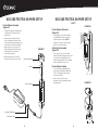
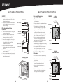
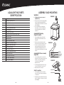
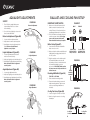
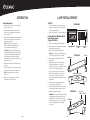
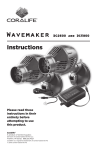
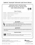
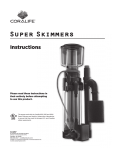
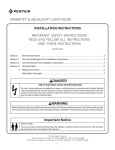
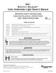
LIMITED WARRANTY
Oceanic warrants that this product shall be free from defective electrical components and leaks or cracks
due to defects in materials or workmanship for a period of twelve months from the date of purchase.
If a defect is shown, Oceanic will, at Oceanic’s sole discretion, either repair or replace the product without
charge. No cash refunds will be made. This warranty is provided solely to the original consumer
purchaser of the product and may not be transferred or assigned.
This warranty does not apply to damage resulting from accident, misuse, abuse, lack of reasonable care,
failure to follow safety and installation instructions, use of the product with non-standard electrical
service, or any other defect not resulting from defects in the electrical components of the product or
defects in materials or workmanship. This warranty will not be effective unless and until the Oceanic
product is shown to have been used in accordance with the safety and installation instructions
accompanying the product, including the requirement that the product be placed on a flat, level surface
designed to support the product.
THIS CONSTITUTES OCEANIC’S ENTIRE WARRANTY AND OCEANIC MAKES NO OTHER
WARRANTIES, WHETHER EXPRESS OR IMPLIED, WITH RESPECT TO THE PRODUCT. OCEANIC
SPECIFICALLY DISCLAIMS ANY AND ALL IMPLIED WARRANTIES, INCLUDING, WITHOUT LIMITATION,
WARRANTIES OF MERCHANTABILITY AND FITNESS FOR A PARTICULAR PURPOSE.
IF OCEANIC CANNOT LAWFULLY DISCLAIM IMPLIED WARRANTIES UNDER THIS LIMITED
WARRANTY, ALL SUCH WARRANTIES, INCLUDING WARRANTIES OF MERCHANTABILITY
AND FITNESS FOR A PARTICULAR PURPOSE ARE LIMITED IN DURATION TO THE DURATION
OF THIS WARRANTY.
OCEANIC IS NOT RESPONSIBLE FOR DIRECT, SPECIAL, INCIDENTAL OR CONSEQUENTIAL DAMAGES
RESULTING FROM ANY BREACH OF WARRANTY OR CONDITION, OR UNDER ANY OTHER LEGAL
THEORY. OCEANIC EXPRESSLY DISCLAIMS ALL ALLEGED DAMAGES FOR LOSS OF AQUATIC LIFE,
PERSONAL INJURY, AND/OR PROPERTY DAMAGE.
Some states and provinces do not allow the exclusion or limitation of incidental or consequential
damages or exclusions or limitations on the duration of implied warranties or conditions, so the above
limitations or exclusions may not apply to you. This warranty gives you specific legal rights, and you may
also have other rights that vary by state or province.
Oceanic shall not have any obligations under this warranty unless the owner notifies Oceanic in writing
of any alleged defect(s) within 30 days of discovery of the defect(s). Any notice to Oceanic must be
delivered by United States or electronic mail to one of the following addresses:
U.S. Mail
Oceanic Systems
5401 W. Oakwood Park Drive
Franklin, Wisconsin 53132
Electronic Mail
[email protected]
Oceanic shall be allowed a reasonable period of time to investigate any warranty claim and to perform
any testing Oceanic deems necessary to determine the cause of the defect. This warranty shall be
interpreted under the laws of the state of Wisconsin.
For additional information regarding this limited warranty, please contact us at the addresses above,
or call us at 800-255-4527.
®
Owner’s Manual
PRODUCT SPECIFICATION
TABLE OF CONTENTS
Glass Aquarium: Size 29
Page 4
Important Safety Instructions
Net Volume: 26 Gallons
Page 6
Grounding
Dimension:
20"l x 20.75"w x 19.25"h
Page 7
BioCube HQI Assembly and Setup Instructions
Page 18
Aqualight HQI Assembly and Setup Instructions
Lighting:
150 Watt, 14,000K,
double-ended metal halide
Page 26
BioCube HQI Maintenance
Back Cover
Warranty and Contact Information
Cooling Fans: 38 mm,
4,000 RPM
Pump Flow Rate:
243 gph (920 L/H)
2
3
IMPORTANT
SAFETY INSTRUCTIONS
1. WARNING – To guard against injury, basic safety precautions should be observed, including the following:
READ AND FOLLOW ALL SAFETY INSTRUCTIONS.
2. DANGER – To avoid possible electric shock, special care should be taken since water is employed in the use
of aquarium equipment. For each of the following situations, do not attempt repairs by yourself; return the
appliance to an authorized service facility for service or discard the appliance:
A. If the appliance falls into the water, DO NOT reach for it! First unplug it and then retrieve it. If electrical
components of the appliance get wet, unplug the appliance immediately.
B. If the appliance shows any sign of abnormal water leakage, immediately unplug it from the power source.
C. Carefully examine the appliance after installation. It should not be plugged in if there is water on parts
not intended to be wet.
D. Do not operate any appliance if it has a damaged cord or plug, or if it is malfunctioning or has been
dropped or damaged in any manner.
E. To avoid the possibility of the appliance plug or receptacle getting wet, position aquarium stand and
tank to one side of a wall-mounted receptacle to prevent water from dripping onto the receptacle or
plug. A “drip loop,” shown in figure below, should be arranged by the user for each cord connecting an
aquarium appliance to a receptacle. The “drip loop” is that part of the cord below the level of the
receptacle, or the connector if an extension cord is used, to prevent water traveling along the cord and
coming in contact with the receptacle (Figure A1). If the plug or receptacle does get wet, DO NOT
unplug the cord. Disconnect the fuse or circuit breaker that supplies power to the appliance. Then,
unplug and examine for presence of water in the receptacle.
FIGURE A1
3. Close supervision is necessary when any
appliance is used by or near children.
Appliance
4. To avoid injury, do not contact moving parts or
hot parts such as heaters, reflectors, lamp bulbs,
and the like.
10. If an extension cord is necessary, a cord with a proper rating should be used. A cord rated for less amperes
or watts than the appliance rating may overheat. Care should be taken to arrange the cord so that it will not
be tripped over or pulled.
11. For added safety, the fixture must be plugged into a receptacle controlled by a GFI (ground fault interrupter)
circuit breaker. Device must be properly connected to a grounded three-prong receptacle.
12. Do not use this appliance in such a way that the vents are restricted or blocked. These vents are necessary
to avoid overheating and ensure safe operating temperature.
13. This appliance is intended FOR HOUSEHOLD USE ONLY.
14. THIS APPLIANCE IS FOR USE OVER COVERED AQUARIUMS ONLY.
SAVE THESE INSTRUCTIONS!
IMPORTANT SAFETY INFORMATION:
Please read the following precautions before use!
1. To reduce the risk of electric shock, always unplug the pump and power cords before performing any
maintenance.
2. Never allow small children to touch, climb-on, or play with the aquarium or its stand. Adult supervision
is required.
3. Never place an aquarium on the floor, it can cause injury or become damaged.
4. Never set an aquarium on an unsturdy or unsupported structure, such as those which are unable to support
the weight of a filled aquarium, are suspended, can rock or sway, can sag, or on wheels or allows the
aquarium to overhang. These could cause the aquarium to leak, crack, or even fall over if a top heavy
situation is created.
5. Aquarium supports that are less than 12" wide (front and back) should be fastened or tethered to a wall
to prevent a top heavy or unstable condition.
6. Do not allow water pump to operate dry at any time.
7. Always observe proper maintenance to ensure optimal operation.
HANDLE WITH CARE!
Always handle aquarium with care to avoid personal injury.
5. Always unplug an appliance from an outlet
when not in use, before putting on or taking off
parts, and before cleaning. Never yank cord to
pull plug from outlet. Grasp the plug and pull to
disconnect.
1. Never lift or attempt to move an aquarium that is not completely empty.
Aquarium
2. Never lift an aquarium with wet hands.
3. Never attempt to lift an aquarium by grasping the upper edges of the frame or from the canopy.
4. Always lift or carry an empty aquarium by supporting it from the bottom of the tank.
6. Do not use an appliance for other than intended
use. The use of attachments not recommended
or sold by the appliance manufacturer may
cause an unsafe condition.
AQUARIUM LOCATION
Power
Supply
Cord
7. Do not install or store the appliance where it will
be exposed to the weather or to temperatures
below freezing.
1. For best results, place an aquarium in a location best suited to support the total weight of the aquarium.
The filled weight of an aquarium is approximately 10-12 lbs. per gallon of water plus the weight of sand,
gravel, rocks or decorations.
2. Always place an aquarium on a flat and level area.
3. Avoid placing an aquarium where it will receive direct sunlight. Full or even partial sunlight can cause
algae growth.
8. Make sure an appliance mounted on a tank is
securely installed before operating it.
4. Keep aquarium in a well ventilated area away from a heating or cooling vent.
9. Read and observe all the important notices on
the appliance.
5. Do not place near electronic components and systems (i.e. TV, stereo systems, etc.).
Drip
Loop
4
5
GROUNDING
BioCube HQI
ASSEMBLY AND SETUP INSTRUCTIONS
Grounding Setup:
Grounding Installation:
This appliance should be grounded to minimize
the possibility of electric shock. This appliance
is equipped with an electric cord having
an equipment grounding conductor and
a grounding type plug. The plug must be
plugged into an outlet that is installed and
grounded in accordance with all appropriate
codes and ordinances.
The green-colored ground terminal (screw, and
the like) extending from the adapter must be
fastened to a permanent ground such as a
grounded outlet box.
1. Plug temporary adapter into two-pole
outlet (Figure A4).
FIGURE A4
Two-Pole Receptacle
This appliance is for use on a nominal 120-volt
circuit, and has a grounding plug that looks like
the plug illustrated in Figure A2.
Temporary Adapter
Screw
FIGURE A2
Grounded Outlet
Rigid Ear
(Grounding Means)
Grounded Plug
Grounded Outlet
Box Cover
2. Insert screw through rigid ear on temporary
adapter and into grounded outlet box
(Figure A5).
FIGURE A5
Grounding Pin
Grounded Plug
A temporary adaptor which looks like the
adaptor shown (Figure A3) may be used to
connect this plug to a two-pole receptacle as
shown in Figure A4, if a grounded outlet is not
available. The temporary adapter should be
used only until a grounded outlet can be
installed by a qualified electrician.
(Temporary adapter not included.)
Temporary
Adapter
Grounded Outlet
Box Cover
Power Strip Setup:
FIGURE A3
1. If using a power strip, the ground connector
must be plugged into a receptacle controlled by
a GFI (ground fault interrupter) circuit breaker.
Two-Pole
Receptacle
Temporary
Adapter
2. Make sure to place the power strip in a dry and
safe area away from the aquarium in order to
avoid moisture.
Rigid Ear
(Grounding
Means)
3. Place power strip in a secure and stable area so
that it cannot fall into the aquarium or sump.
4. Make sure all receptacles are protected from
water: splash, spilling and evaporation.
6
7
BIOCUBE HQI
PARTS IDENTIFICATION
BIOCUBE HQI PARTS DIAGRAM
Part #
1
1
2
3
4
5
6
7
8
9
10
11
12
13
2
3
4
5
6
7
11
Description
Item #
Left Filtration Cover
Right Filtration Cover
Glass Canopy
Filter Cartridge
82105
Overflow Tray
Output Elbow Attachment
Flexible Tubing
Water Pump
82007
Output Discharge Nozzle
BioCube Glass Aquarium
BioCube Protein Skimmer (see pages 10 and 11 for parts/identification) 82053
Refugium Strainer
Sponge Filter
12
8
13
9
10
8
9
PROTEIN SKIMMER DETAILED DIAGRAM
PROTEIN SKIMMER
PARTS IDENTIFICATION
Part #
1
2
3
4
5
6
7
8
9
10
1
2
3
4
5
Description
Collection Cup Lid
Collection Cup
Reaction Chamber Top
Suction Cup
Airstone
Reaction Chamber Assembly
Airline Tubing 7'
Air Pump
Inline Air Flow Valve
Check Valve
6
4
7
8
9
10
10
11
BIOCUBE PROTEIN SKIMMER SETUP
Protein Skimmer Assembly
(Figure C1)
(con't)
FIGURE C2
Protein Skimmer Placement
(Figure C2)
1. Insert airline tubing into air pump using
end that has just 6" before the inline
air flow valve.
1. Using hanging clip on reaction chamber
top, hang protein skimmer on the wall
between chambers 1 and 2. NOTE: if
skimmer is in correct position, the right
filtration cover will fit properly.
2. Remove reaction chamber top from
reaction chamber and insert the other
end of the airline tubing through the hole
at the bottom of the reaction chamber.
3. Attach the airstone to the end of the
airline tubing and pull it back through
until the airstone is at the bottom
of the reaction chamber.
4. Reassemble all parts of the protein
skimmer, except for the collection cup.
BIOCUBE PROTEIN SKIMMER SETUP
FIGURE C1
Reaction Chamber Top
Airstone
Collection Cup Assembly
(Figure C3)
1. Place collection cup on top of reaction
chamber. Pull airline tubing through the hole
on the back of the right filtration cover,
making certain that airflow is not restricted
when the right filtration cover is on.
Protein Skimmer Startup
1. Once water has been added (page 23),
plug in pump. Adjust airflow adjustment
nozzle so that bubbles stay just above
the reaction chamber.
Reaction Chamber
2. When collection cup fills, remove
and dispose of waste material by rinsing
with warm water.
FIGURE C3
6" Length of Airline Tubing
Inline Air Flow Valve
12
13
BIOCUBE FILTER SETUP
BIOCUBE FILTER STARTUP
SAFETY:
Filter Startup Operation
(Figures C5 and C6)
1. Turn off all switches and unplug all power
cords from outlet or power source before
performing maintenance.
FIGURE C4
2. Visually inspect the aquarium and all parts
prior to installation to make sure nothing
has been damaged.
2. Prepare saltwater for aquarium, making sure
water is at room temperature.
Overflow Tray
Protein Skimmer
2. Place protein skimmer in chamber 1 after
proper assembly and according to proper
placement instructions (pages 20-21).
CHAMBER
3
CHAMBER
2
3. Remove filter cartridge from the overflow
tray in chamber 2 and its packaging. Rinse
thoroughly with cool freshwater and
reinstall in the overflow tray.
CHAMBER
1
4. Plug water pump cord into an outlet or
power source. Pump will raise the water
level in the aquarium section while draining
into the filtration section (Figure C6).
Fill
Level
5. Observe and make sure that the water
circulation is flowing properly from the
aquarium section into the filtration section.
Aquarium
Section
6. Place glass top on aquarium.
Aquarium Divider
Output Discharge
Nozzle
4. Make sure that the overflow tray and
refugium strainer are properly placed inside
chamber 2.
Top Moulding
3. Slowly add water to the aquarium. Make
sure to fill aquarium to the lower edge of
the top moulding (Figure C5).
Refugium Strainer
Water Pump
Sponge Filter
1. Remove left and right filtration covers, glass
canopy and Aqualight HQI.
INITIAL
FILL LEVEL
1. Add substrate, rocks and décor
to the aquarium.
Filter Cartridge
Filter Assembly and Setup
(Figure C4)
FIGURE C5
Filtration
Section
7. Attach and plug in Aqualight HQI according
to instructions (page 10).
Surface Intake
Bottom Intake
8. Once aquarium and filtration have run for
two days, and everything is functioning
properly, add livestock to the aquarium.
5. Make sure that the sponge filter is correctly
placed in chamber 3.
FIGURE C6
FILL LEVEL
AFTER FILTER STARTUP
Precautions for Optimal Filter
Performance
6. Make sure that the water pump is properly
assembled and connected to the return
output discharge nozzle.
COMPLETED FILTER
ASSEMBLY
1. Do not block or obstruct output discharge
nozzle.
2. Do not block or obstruct surface or bottom
level intakes.
Original
Fill Line
3. Perform scheduled maintenance and
change filter cartridge as directed.
4. Observe scheduled maintenance on
water pump.
Plug
In
New
Fill Level
5. Make sure to perform scheduled water
changes and BioCube filter maintenance
according to instructions (page 26).
Aquarium
Section
Filtration
Section
14
15
REFUGIUM SETUP AND REFUGIUM
LIGHT INSTALLATION
SAFETY:
BIOCUBE FILTER OPERATION
FIGURE C8
BioCube Filtration Stages
(Figures C8–C10)
1. Turn off all switches and unplug all power
cords from outlet or power source before
performing maintenance.
1. Water flows from aquarium into the surface
and bottom intakes into chamber 1 where
some enters the protein skimmer
(Figure C8). The protein skimmer removes
many harmful organic materials from
the water.
Refugium Setup With Refugium
Light (not included)
1. Remove left and right filtration covers.
2. Remove overflow tray and filter cartrige
from center filter chamber.
3. Once the BioCube aquarium is fully set
up and ready to support livestock, add
substrate and macroalgae to the refugium
chamber. Replace overflow tray, filter
cartridge and left and right filtration covers.
FIGURE C7
FIGURE C9
Refugium Light Installation
(Figure C7)
2. From chamber 1, water flows over the top
of and through the filter cartridge into
the refugium in chamber 2 (Figure C9).
Live macroalgae and live rock in the
refugium remove excess nutrients and add
oxygen to the water while helping stabilize
the pH level.
1. Locate window on the back of the BioCube HQI.
2. Clean area around the illumination window
with a dry cloth to remove any dust,
salt or water.
3. Follow instructions included with the
refugium light to mount to BioCube HQI.
3. From the refugium, water flows into
chamber 3 through the sponge filter
and into the water pump (Figure C10).
The water pump then forces the water
through the flexible tubing and back into
the aquarium through the discharge nozzle.
16
FIGURE C10
17
Aqualight HQI
ASSEMBLY AND SETUP INSTRUCTIONS
AQUALIGHT HQI PARTS DIAGRAM
1
2
15
3
4
5
6
7
8
9
16
10
11
17
12
13
14
18
19
18
19
AQUALIGHT HQI PARTS
IDENTIFICATION
Part #
1
2
3
4
5
6
7
8
9
10
11
12
13
14
15
16
17
18
19
ASSEMBLY AND MOUNTING
WARNING:
FIGURE B1
1. This fixture is for use over covered
aquariums only.
Description
Aqualight Lighting Hood
Lamp Holder
Angle Adjustment Knob
Male (A) Connection Knob
Side End Panel
HQI Glass Lens Cover
Double-Ended HQI Metal Halide Lamp
Extension Arm
Ventilation Grill
Height Adjustment Knob
Female (B) Connection Knob
Hang-On Tank Mount Base
Tank Mount Bracket
Tank Mount Screws (3)
Extension Adjustment Knob
Ballast Connection
Cooling Fan Connection
HQI Metal Halide Ballast
Cooling Fan Adaptor
2. Always turn fixture off and unplug ballast
power cord before adjusting fixture or
replacing lamps. Let the fixture cool down
before handling.
3. Do not attach fixture to ballast until
all assembly connections, adjustments
and mounting setups are completely
performed.
Aqualight HQI Mounting
(Figures B1 and B2)
1. Place Aqualight tank mount bracket
between the two rear filtration covers
(Figure B1).
2. Hold the tank mount bracket in place
and remove the two rear filtration covers.
FIGURE B2
3. Continue to hold tank mount bracket
in place and fasten tank mount screws
(Figure B2). Hand tighten tank mount
screws until tank mount bracket is securely
in place.
Molding
Aqualight HQI Fixture Assembly
(Figure B3)
Tank Mount
Screws (3)
Glass
1. Connect lighting hood (Connection A),
with male connection knob to tank mount
bracket (Connection B), with female
connection knob using height
adjustment knob.
FIGURE B3
2. Screw height adjustment knob through
Connection B and into Connection A.
3. Adjust and secure connection.
Safety Precautions:
Connection A
1. Do not plug BioCube into an outlet or
power source until setup and installation
is completed.
Connection B
2. Visually inspect the aquarium and canopy
prior to installation to make sure it has not
been damaged.
20
21
AQUALIGHT ADJUSTMENTS
SAFETY:
FIGURE B4
1. Turn off switch, unplug ballast power
cord and allow fixture to cool down
before handling.
Extension Adjustment
2. Do not let the top lighting hood come into
direct contact with water.
BALLAST AND COOLING FAN SETUP
FIGURE B7
IMPORTANT SAFETY NOTES:
1. Make sure to follow the fixture and HQI
ballast connection instructions in their
entirety. Failure to follow these directions
may damage ballast and/or cause failure.
MALE
FEMALE
2. Turn off all switches and unplug all power
cords from power outlet(s). Do not plug
power cords into power outlets until
fixture installation and setup is complete.
Extension Adjustment (Figure B4)
1. Loosen extension adjustment knob.
2. Adjust extension arm to desired position.
Ballast Setup (Figure B7)
3. Hand tighten extension adjustment knob
firmly. Make sure that the fixture is
tightened securely in place.
1. Locate double-ended HQI metal halide
lamp connector on unit.
Height Adjustment (Figure B5)
FIGURE B5
1. Loosen height adjustment knob until
extension arm moves freely.
Height Adjustment
Double-ended
HQI Metal Halide
Lamp Connector
2. Make sure that the double-ended HQI metal
halide ballast is unplugged and switch is in
the "off" position.
3. Align the male pins on the double-ended
HQI metal halide lamp connector with
the female pin inlets on the double-ended
HQI metal halide ballast connector
and connect. IMPORTANT! Make sure that
the lamp connector is fully seated into the
ballast connector.
2. Adjust top lighting hood to desired position.
3. Hand tighten height adjustment knob firmly.
Make sure that the fixture is tightened
securely in place.
Angle Adjustment (Figure B6)
1. Loosen angle adjustment knobs.
FIGURE B8
Ballast
Mounting
Hardware
Mounting HQI Ballast (Figure B8)
2. Adjust top lighting hood to desired position.
3. Hand tighten angle adjustment knobs firmly.
Make sure that the fixture is tightened
securely in place.
Double-ended
HQI Metal Halide
Ballast Connector
THIS STEP IS OPTIONAL
1. Slide out ballast-mounting bracket.
FIGURE B6
Angle Adjustment
2. Place metal washer between screw and
ballast mounting bracket. Tighten screw
until secure (mounting hardware not
included).
FIGURE B9
Cooling Fan Setup (Figure B9)
1. Locate cooling fan connector on fixture.
2. Attach cooling fan connector to cooling
fan adaptor.
Cooling Fan
Connector
22
23
Cooling Fan
Adaptor
OPERATION
LAMP REPLACEMENT
Startup Operation
SAFETY:
1. Make sure all connections are completely
attached and secure.
1. Turn off all switches and unplug all power
cords from outlet or power source before
performing maintenance.
2. Make sure that all switches are in the off
position before plugging in power cords
to power source.
2. Make sure the unit is cool before handling.
Double-Ended HQI Metal Halide
Lamp Replacement
(Figures B10–B12)
3. Plug double-ended HQI metal halide ballast
power cord into an outlet or power source
and turn the switch on.
NOTE: It may take 5-10 minutes for
double-ended HQI metal halide lamp
to reach maximum light intensity.
1. Remove the fixture from the aquarium.
CAUTION: When the double-ended HQI
metal halide ballast is turned off, wait until
the double-ended HQI metal halide lamp
has completely cooled before turning
ballast back on. Lamp may not turn on if not
completely cooled.
3. Remove the side panel (Figure B10).
Aqualight Hood
2. Place fixture on a non-abrasive flat surface
with the bottom facing up.
NOTE: side end panel is located at the end
of the fixture, opposite the cooling fan.
4. Slide ventilation grill off of the fixture
(Figure B10).
Ventilation
Grid
FIGURE B11
Side End
Panel
LIFT UP
PRESS IN
5. Detach glass lens cover from the lamp
holder by pushing the cover into the
opposite end to free one side of the cover
from the cover clamps (Figure B11).
4. Verify that the lamp is lit and functioning
properly.
5. Plug cooling fan power cord into an outlet
or power source and turn the switch on.
FIGURE B10
6. Use a soft cloth to grab one end of the
lamp. Push the lamp into the opposite
end to free one side of the lamp from
the double-ended HQI metal halide socket
(Figure B12).
NOTE: Cooling fan must be on while
lamp is on.
6. Make sure cooling fans are on and are
blowing freely across the unit.
HQI Glass Lens Cover
7. Gently lift the lamp up at an angle and
remove the lamp (Figure B12).
Lamp Holder
8. Carefully install replacement double-ended
HQI metal halide lamp using a soft cloth.
FIGURE B12
9. Replace all light fixture parts.
WARNING: Do not touch double-ended HQI
metal halide lamp with fingers, as the oils
may damage the lamp. If contact is made
with the lamp, use a clean, soft, dry cloth to
remove any fingerprints from the lamp
before use.
Use Soft
Cloth LIFT UP
PRESS IN
Lamp Holder
24
25
BIOCUBE MAINTENANCE
WARNING!
BIOCUBE MAINTENANCE (con't)
Monthly Maintenance
(Figures C12–C14)
1. Make sure all switches are in the off position
and unplug power cords from power source
or outlet before performing maintenance.
FIGURE C12
2. Wash hands thoroughly with soap and
water before performing maintenance
to avoid contamination of the aquarium.
tilt up
1. Replace used filter cartridge by tilting the
filter back from one end of the overflow
tray, then pulling out. Discard. Rinse new
filter cartridge with freshwater before
installing (Figure C12).
Pul
l aw
ay
2. Remove sponge filter from water pump.
Rinse and clean sponge with cool
freshwater to remove accumulated organic
buildup (Figure C13).
Daily Maintenance (Figure C11)
1. Visually observe the BioCube lighting and
filtration to make sure that the system is
functioning properly.
3. Disconnect water pump from output elbow
attachment and flexible tubing. Disassemble
pump and impeller. Rinse and wipe down all
parts to dislodge debris. If calcium buildup
is present, soak in a vinegar solution with
one part vinegar to one part water for one
hour, then rinse thoroughly.
2. Check water level. Make sure to replace
evaporated water with freshwater to
replenish water supply. Do not let water
get below the minimum water level.
Weekly Maintenance
1. Keep BioCube surfaces clean from dust and
debris. Wipe exposed surfaces with a clean
and dampened soft terrycloth.
FIGURE C13
Filter Cartridge
Overflow Tray
Sponge Filter
4. Disassemble pump and impeller. Rinse
and wipe down all parts to dislodge debris
and particulate matter (Figure C14).
2. Remove glass top and wipe down with a
dampened soft terrycloth to remove salt
buildup.
FIGURE C11
3. Inspect filtration system for clogging and
excessive accumulation of debris. Clean and
remove debris from surface and bottom
intakes and overflow tray. Rinse parts in
freshwater if needed.
9–12 Month Maintenance
1. Replace Aqualight HQI metal halide bulb
every 9-12 months by following the lamp
replacement instructions on page 14.
For optimal performance, always use
Coralife brand 150 Watt Double-Ended
HQI replacement lamps.
FIGURE C14
Minimum
Water Level
Pump Housing
26
Pump Impeller
Ceramic Shaft
27
Impeller Cover