1
for variable-speed drives up to
90 kW
MICROMASTER
MICROMASTER Vector
MIDIMASTER Vector
CATALOG
Catalog DA 64
2002 / 2003
DA64
SIEMENS
> empty page<
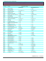
1.
MICROMASTER
MICROMASTER Vector
MIDIMASTER Vector
Product overview
Technical data
Conformance to International Standards
Quotation text
2.
Variable-Speed
Drives up to 90kW
Catalog DA 64 - 2002/03
Introduction
Technical Description
Power section
Closed-loop control
Brakes
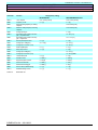
3.
Engineering information
Technical comparison table
Dimensions and weights
Degrees of protection
Control connections
EMC filter
Reactors
Information on how to select a motor
Braking resistors
Electronic braking module
4.
Communications / interfaces
Standard operator panel
Serial RS485 interface
Plain text operator panel (option)
RS232 interface
PROFIBUS module CB15 (option)
Open-loop control and commissioning using DRIVE-MONITOR
Diagnostic functions, error codes and parameter lists
5.
Drive inverter selection & ordering data
MICROMASTER / MICROMASTER Vector
MIDIMASTER Vector
6.
Options
Overview of the options
Ordering data for filters
Ordering data for reactors
Ordering data for braking resistors
Ordering data for braking modules
Fuses
> empty page <
INTRODUCTION
MICROMASTER
MICROMASTER Vector
MIDIMASTER Vector
1.
Introduction
1/1
1.1
Product overview
1/1
1.2
Technical data
1/2
1.3
Conformance to International Standards
1/3
1.4
Quotation text
1/5
SIEMENS DA 64 – 2002/2003
Version D
1/0
INTRODUCTION
MICROMASTER
MICROMASTER Vector
MIDIMASTER Vector
> empty page <
SIEMENS DA 64 – 2002/2003
1/1
Version D
INTRODUCTION
MICROMASTER
MICROMASTER Vector
MIDIMASTER Vector
1.
INTRODUCTION
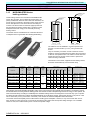
The MICROMASTER, MICROMASTER Vector and
MIDIMASTER Vector drive inverters use state-of-the-art
IGBT power semiconductors and represent the result of
years of experience in the area of drive inverter
development.
A complete series extending from 120 W to 75 kW or up to
90 kW for applications with square-law load characteristics is
available. They operate, as standard using the highperformance sensorless vector control. This offers the user
the benefits of high torque and dynamic performance across
a broad range of applications.
A parallel range of MICROMASTER drives from 120 W to 7.5
kW is especially suitable for driving basic machines.
COMBIMASTER (refer to Section 8) combines motor and
inverter in one compact unit and is one of our top-of-the-line
variable-speed drive products.
A high degree of user friendliness, an excellent
price/performance ratio, compact dimensions are just some
of the features of this product series. Furthermore, this series
fulfills the highest quality and reliability standards worldwide.
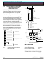
1.1
Product overview
MICROMASTER, MICROMASTER Vector and
MIDIMASTER Vector have been designed for use worldwide
and are suitable for a wide range of supply voltages:
1/3 phase
208 - 240 V AC ±10%
3 phase
380 - 500 V AC ±10%
3 phase
Vector)
525 - 575 V AC ±15% (only MIDIMASTER
Two operational characteristics are provided in these drive
series:
-
MICROMASTER Vector and MIDIMASTER Vector offer
high performance, sensorless vector control for a high
torque at low speeds as well as excellent dynamic
characteristics in operation. This is the reason that these
drives can even be used in sophisticated applications, for
example, elevators, cranes and industrial washing
machines.
-
MICROMASTER has, as standard, a V/Hz control and is
especially suitable for basic applications such as pumps
and fans.
-
Both of these drive types also profit from a PID controller
which is integrated as standard (PI for MICROMASTER)
for the closed-loop control.
-
Furthermore, all of the products have the same userfriendly standard interface with seven keys and an LED
display.
-
User-friendly screwless terminals are used to connect the
control wiring.
-
Up to 31 drives can be connected to a PLC or PC system
through a standard serial RS485 interface.
-
A drive can be enabled via the keyboard, a digital input or
the standard serial RS485 interface.
-
The setpoint for the motor speed can either be selected
via a digital setpoint, a motorized potentiometer, a fixed
frequency, an analog input or the serial link.
-
Mixed mode control is also available, allowing drive
control and setpoint inputs to be from different sources.
-
An integrated DC current brake allowing DC voltage to be
output, even when the motor is stationary.
-
The drives can be parameterized so that they
automatically restarted after a power failure or a fault.
-
The parameter sets of the various product types are
completely compatible, so that the training time is
reduced to a minimum.
-
All of the drives are certified in accordance with VDE, UL
and UL Canada and have been manufactured in
compliance with the ISO9001 Standard.
-
All of the drives conform to the requirements of the
European Low-Voltage Directive 73/23/EC and have the
CE Mark.
-
The drive inverters do not process any date-related
information and were therefore not influenced by the year
2000 issues.
Comment:
However, the following should be noted for this voltage data:
-
-
The drive inverter operating range is between the two
specified voltage values - from e.g. 208 - 240V
The specified ±10% is not an operating range, it
represents a range for brief voltage fluctuations.
SIEMENS DA 64 – 2002/2003
Version D
1/2
INTRODUCTION
MICROMASTER
MICROMASTER Vector
MIDIMASTER Vector
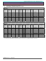
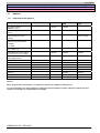
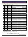
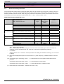
1.2
Technical data
Drive inverter
MICROMASTER
Line supply voltage
MICROMASTER
Vector
MIDIMASTER Vector
1-ph. 208 V – 240 V AC ±10%
3-ph. 208 V – 240 V AC ±10%
3-ph. 380 V - 500 V AC ±10%
1-ph. 230 V AC
3-ph. 230 V AC
3-ph. 400 V AC
3-ph. 575 V AC
3-ph. 208 V - 240 V AC ±10%
3-ph. 380 V - 500 V AC ±10%
3-ph. 525 V - 575 V AC ±15%
120 W – 3.0 kW
120 W – 4.0 kW
370 W – 7.5 kW
Degree of protection
5.5 (VT 7,5) kW - 45 (VT 45) kW
11 (VT 15) kW - 75 (VT 90) kW
2.2 (VT 4) kW - 37 (VT 45) kW
IP20/NEMA1
IP21/NEMA1 or IP56
Integrated filter
External filter
Integrated / external filter
xxx
xxx
Internal / external filter
Internal / external filter
xxx
External filter
External filter
External filter
xxx
xxx
External filter
External filter
xxx
0 – 50°C
0 – 40°C
In conformance with EN 55011,
Class A for
1-ph. 230 V AC
3-ph. 230 V AC
3-ph. 400 V AC
3-ph. 575 V AC
In conformance with EN 55011,
Class B for
1-ph. 230 V AC
3-ph. 230 V AC
3-ph. 400 V AC
3-ph. 575 V AC
Temperature range
Control technique
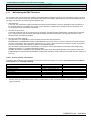
Overload capability 1)
Protective functions
V/Hz
Sensorless vector control, FCC, V/Hz
150% rated output
current
for 60 s
150% rated output current for 60 s
200% rated output current for 3 s
Undervoltage, overvoltage, overload, short-circuit, ground fault, motor failure, motor overtemperature, drive
inverter overtemperature
Max. motor cable length
Frequency range
Refer to Section 3
0 - 400 Hz
0 - 650 Hz
Setpoint resolution
Digital inputs
6, parameterizable (24 functions)
7
8
Ramp-up/ramp-down times
2
Relay outputs
1, parameterizable
110 V AC / 0.3 A
30 V DC / 1.0 A
Analog inputs
1
Analog outputs
-
2, parameterizable
240 V AC / 0.8 A
30 V DC / 2 A
2
1, parameterizable
Serial interfaces
Dynamic braking
Internal technology controller
0 - 650 Hz
0.05 Hz
3, parameterizable
(19 functions)
Fixed frequencies
Refer to Section 3
2, parameterizable
RS485
Compound braking
PI
Braking chopper
External braking module
PID
1
) The overload capability refers to the rated output currents of the MICROMASTER and MICROMASTER Vector drives as well as
the rated output currents for constant torque operation (CT) of the MIDIMASTER Vector. It is valid for a 5 minute load duty cycle.
This means that the drive units can have an overload condition of 50% for a total of 1 minute within a 5 minute period.
Table 1:
Technical data
SIEMENS DA 64 – 2002/2003
1/3
Version D
INTRODUCTION
MICROMASTER
MICROMASTER Vector
MIDIMASTER Vector
1.3
Conformity to International Standards
1.3.1
CE Mark:
The MICROMASTER, MICROMASTER Vector and MIDIMASTER Vector drive inverters fulfill the requirements of the Low-Voltage
Directive 73/23/EC and therefore have the CE Mark. A certificate of conformance can be issued when required. The drive units are
certified in compliance with the following Standards:
EN60204-1
Safety of Machinery, Electrical Equipment of Machines
EN60146-1-1
Semiconductor inverters; General requirements and line commutated inverters
1.3.2
Electromagnetic compatibility:
MICROMASTER, MICROMASTER Vector and MIDIMASTER Vector drive inverters, fulfill, when correctly installed and used in-line with
the specifications, the requirements of Directive 89/336/EC regarding electromagnetic compatibility. When all of the Guidelines to reduce
the effects of electromagnetic radiation are followed when installing the drive units, then all of the requirements for the CE certification of a
machine will be fulfilled.
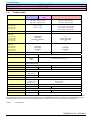
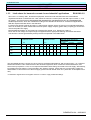
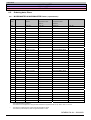
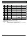
The following table lists the results (measured) with reference to emission and noise immunity of the MICROMASTER,
MICROMASTER Vector and MIDIMASTER Vector drive inverters. The drive inverters were installed corresponding to the
appropriate guidelines using shielded motor cables, shielded control cables and the line filters which are available as
accessory (with the exception of single-phase units):
Test
Measurement
Test value
HF noise EN55011 (VDE0875 Part 11) and
EN55022 (VDE 0878 Part 22)
Conducted through the line supply
cable and radiated through air
ESD immunity
EN61000-4-2 (VDE 0847 Part 4-2)
Immunity to electric fields
EN61000-4-3 (VDE 0847 Part 4-3)
Noise immunity to noise pulses (burst)
EN61000-4-4 (VDE 0847 Part 4-4)
ESD through air discharge
ESD through contact discharge
Electric field is applied to the unit
1/3 phase 230/400/460V AC with
integrated filter
>= Class A
1/3 phase with external filter >= Class B
(only cable-borne noise)
Level 4: 15 kV
Level 4: 8 kV
10 V/m
8 kV
4 kV
26-1000 MHz 10 V/m
Level 4: 4 kV
Level 4: 4 kV
4 kV
Level 4: 4 kV
Level 4: 4 kV
2 kV
2 kV
2 kV
2 kV
2 kV
4 kV non-symmetrical
2 kV symmetrical
4 kV non-symmetrical
2 kV symmetrical
Surge immunity
EN61000-4-5 (VDE 0847 Part 4-5)
Table 2:
Connected to all cable
connections:
Line supply cable
Motor cable
Control cables
Braking resistor/module cable
DC link cable
Connected to all line supply cables:
Limit value acc. to
EN50081/EN50082
Class A
Class B
EMC conformity
SIEMENS DA 64 – 2002/2003
Version D
1/4
INTRODUCTION
MICROMASTER
MICROMASTER Vector
MIDIMASTER Vector
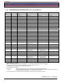
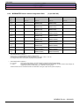
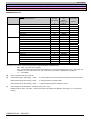
1.3.3
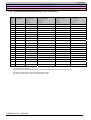
Limit values for harmonic currents in non-industrial² applications
EN 61000-3-2
st
Since the 1 of January 2001, all electrical equipment, which fall under the EMC Directive must fulfill the
regulations laid down in EN 61000-3-2 "Limit values for harmonic currents (drive units with input currents <= 16 A
per phase)". All of the Siemens MICROMASTER, MIDIMASTER, MICROMASTER Eco and COMBIMASTER
variable-speed drives, which are classified according to the Standard as devices for "Professional applications"
fulfill the requirements laid down in the Standard.
For drives with 250 W to 550 W and 230 V 1-phase power supplies, which are used in non-industrial applications,
then it is necessary to obtain authorization from the power supply company [power utility company] to connect the
units to the public line supply.
More detailed information on this subject is provided in EN 61000- 3-12, Sections 5.3 and 6.4.
Drive units in this voltage and output range are supplied with the appropriate warning information and labels:
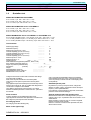
The harmonic currents generated by these products are specified in the table below:
Nominal value
250W / 230V /
1AC
370W / 230V /
1AC
550W / 230V /
1AC
Table 3:
Typical
harmonic current
Typical
harmonic current
Typical voltage distortion
Nominal values, distribution
transformer
10 kVA
100 kVA
1 MVA
THD (%)
THD (%)
THD (%)
0.77
0.077
0.008
(A)
3.
2.15
5.
1.44
7.
0.72
9.
0.26
11.
0.19
(%)
3.
5.
83 56
7.
28
9.
10
11.
7
2.96
2.02
1.05
0.38
0.24
83
56
28
10
7
1.1
0.11
0.011
4.04
2.70
1.36
0.48
0.36
83
56
28
10
7
1.5
0.15
0.015
EMC conformance in non-industrial applications
The permissible harmonic currents for “Drive units for professional applications” with an input power > of 1 kW have
still not been defined. This means that all of the electrical equipment, which contain the drives listed above, and
which have input powers >1 kW, do not require authorization before being connected to the line supply. Alternatively,
by installing the input reactors, recommended in the "Options" Section, means that it is not necessary to apply for
authorization to connect the unit to the line supply (drive units with 550 W 230V AC 1 phase are an exception to this
rule).
² Industrial line supplies are those supplies which are not used to supply residential buildings.
SIEMENS DA 64 – 2002/2003
1/5
Version D
INTRODUCTION
MICROMASTER
MICROMASTER Vector
MIDIMASTER Vector
1.4
Quotation text
6SE92 MICROMASTER IP20/NEMA1
0.12 to 3 kW, 1-ph. 208 - 240 V AC +/- 10%
0.12 to 4 kW, 3-ph. 208 - 240 V AC +/- 10%
0.37 to 7.5 kW, 3-ph. 380 to 500 V AC +/- 10%
6SE32 MICROMASTER Vector IP20/NEMA 1
0.12 to 3 kW, 1-ph. 208 - 240 V AC +/- 10%
0.12 to 4 kW, 3-ph. 208 - 240 V AC +/- 10%
0.37 to 7.5 kW, 3-ph. 380 to 500 V AC +/- 10%
6SE32 MIDIMASTER Vector IP21/NEMA1 or IP56/NEMA 4/12
5.5 to 45 kW (variable torque: 7.5 to 45 kW), 3-ph. 208 – 240 V AC +/- 10%
11 to 75 kW (variable torque: 11 to 90 kW), 3-ph. 380 to 500 V AC +/- 10%
2.2 to 37 kW (variable torque: 4 to 45 kW), 3-ph. 525 to 575 V AC +/- 15%
Technical data
Rated supply voltage
Rated line frequency
.................
.................
V
Hz
Rated output current at M = const.
.................
A
Overload capability (up to 50 % for 60 s)
.................
A
Overload capability (up to 100 % for 3 s)
.................
A
Rated output current at M~ n²
.................
A
Overload capability (up to 10 % for 60 s)
Rated output at M = const.
.................
kW
Rated output at M ~ n²
.................
kW
Output frequency
from.......... to.........
Hz
Radio interference suppression (EN55011, Class A or B)
.................
Max. ambient temperature (40/50 ºC)
.................
ºC
Degree of protection (IP20/IP21/IP56)
.................
Dimensions
(HxWxD)
........x........x...... mm
Weight
.................
kg
MICROMASTER, Order No.
.................................
MICROMASTER Vector, Order No.
.................................
MIDIMASTER Vector, Order No.
.................................
Voltage-source DC link inverters with constant DC link voltage
and pulse-width modulation.
State-of-the-art power transistors in the inverter (IGBT
technology) ensure optimum speed control of three-phase
motors.
Fully-digital microprocessor-based open and closed-loop control.
All of the drive units are UL and cUL-certified and designed and
constructed in compliance with VDE/EN.
They fulfill the requirements of the European Low-Voltage
Directive 73/23/EEC (EN 60204-1 and EN 60146-1-1) and have
the CE Mark.
V/Hz control with parameterizable voltage boost (6SE92).
Field-orientated closed-loop vector control where the output
current is precisely monitored and with a self-adapting motor
model (6SE32).
Power sections
Optional intelligent plain text operator panel
Incoming rectifier as uncontrolled diode bridge circuit.
High temperature-resistant DC link capacitors to smooth the DC
link voltage. Six-pulse output inverter with IGBTs.
Pre-charging device
Pre-charging circuit with switching relay.
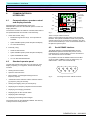
Standard operator panel
Keys/buttons to power-up and power-down, changes the
direction of rotation, jogging, increase and reduce the output
frequency and for parameterization.
Four-character 7-segment display for setpoints, actual values,
parameter values and fault messages.
Illuminated dot matrix LCD for multi-lingual menu-prompted
operator control. Up to 10 parameter sets can be saved in a nonvolatile fashion.
Master operation to network a max. of 31 drives. Integrated
interface converter RS232 / RS485.
Direct PC connection to read and write parameter sets, also
without a drive inverter.
Motor control (open-loop)
SIEMENS DA 64 – 2002/2003
Version D
1/6
INTRODUCTION
MICROMASTER
MICROMASTER Vector
MIDIMASTER Vector
Control terminal strip for external operator control
Output current limiting and monitoring
MICROMASTER 6SE92
3 parameterizable 24 V digital inputs with 18 selectable
functions. 1 parameterizable relay output (floating 30V DC /
1A, 110V AC / 0.3A) with 13 selectable functions. 1 analog
input for setpoint input or PI controller actual value
feedback 0/2 -10 V.
15 V/50 mA power supply for PID encoder and digital
inputs.
10 V/10 mA power supply for the setpoint potentiometer.
A PTC motor temperature sensor can be evaluated using a
digital input.
All of the inputs and outputs are short-circuit proof.
Integrated PID control (PI control for 6SE92) for e.g.
closed-loop pressure or temperature control. Serial RS485
interface for the USS protocol. Integrated programmable
sequence control to control an external brake. Restart-onthe-fly circuit to power-up the drive inverter to a motor
which is already spinning. Automatic restart after line failure
or fault. Flexible setpoint input using fixed frequencies,
motorized potentiometer, jogging setpoint, via analog input
or serial interface. Flexible control using keypad, digital
inputs or serial interface.
Integrated, adjustable DC current brake.
Combined braking to quickly shutdown without external
components. Additive setpoint input via an analog input
and fixed frequencies/digital setpoint input as well as
control via various sources.
Programmable ramp-function generator (0 - 650 s) with
rounding-off capability.
8 fixed frequencies, parameterizable (7 for 6SE92).
4 frequency ranges can be suppressed to avoid resonance
effects.
The drive units have an integrated EMC filter as standard
corresponding to EN55011 Class A for drive units with
single-phase line supply connection.
MICROMASTER Vector 6SE32
MIDIMASTER Vector 6SE32
6 parameterizable 24 V digital inputs with 23 selectable
functions. 2 parameterizable relay outputs (floating, 30V
DC / 2A, 240V AC / 0.8A) with 13 selectable functions.
1 analog input for 0/2 -10 V, +/- 10V,
0/4 - 20 mA setpoint input. 1 additional analog input for
setpoint input or PID controller actual value feedback 0/2 10 V, 0/4 – 20 mA. 1 parameterizable analog output with 6
selectable functions 0/4 - 20mA (MICROMASTER Vector).
2 parameterizable analog outputs, each with 6 selectable
functions (MIDIMASTER Vector).
1 connection for a PTC motor temperature sensor.
15 V/50 mA power supply for PID encoder and digital
inputs.
10 V/10 mA power supply for the setpoint potentiometer.
All of the connections are short-circuit proof.
Standard automation interface
Serial RS485 interface with USS protocol to connect a
max. 31 drives; max. data transfer rate is 19.2 kbit/s.
Optional automation interface
PROFIBUS DP module to connect a max. of 125 drives,
maximum data transfer rate is 12 Mbit/s.
CAN bus module, supports the CAN OPEN protocol
Standard functions for
MICROMASTER 6SE92
MICROMASTER Vector 6SE32
MIDIMASTER Vector 6SE32
V/Hz speed control for one or several asynchronous,
synchronous or reluctance motors
Output frequency for 6SE32: 0 - 650Hz (only in V/Hz or
FCC control in vector control only 325Hz is possible) and
0.01 Hz resolution of the output frequency
Output frequency for 6SE92: 0 - 400 Hz and 0.05Hz
resolution of the output frequency
Overload capability is 50 % referred to the rated output
current for a load duty cycle of 60 seconds within a 5 min
period.
Integrated motor protection functions
PTC input (MICROMASTER via digital input)
I²/t monitoring
Additional standard functions
MICROMASTER Vector 6SE32
MIDIMASTER Vector 6SE32
Sensorless vector control for dynamic operating
characteristics and high speed stability for three-phase
asynchronous motors.
Overload capability 100 % referred to the rated output
current for 3 seconds.
Integrated braking chopper with parameterizable load duty
cycle (MICROMASTER Vector).
Accessories
Sub-chassis radio interference suppression filter
(with the voltage series 208 - 240V & 380 – 480V)
for MICROMASTER and MICROMASTER Vector
corresponding to EN55011, Class A or Class B
External radio interference suppression filter
(with the voltage series 208 - 240V & 380 – 460V)
for MIDIMASTER Vector corresponding to EN55011
Class A or Class B
Line supply fuses (incl. semiconductor protection)
Line reactors
Braking resistors
(MICROMASTER Vector, MIDIMASTER Vector)
Braking modules
(MIDIMASTER Vector)
Output dv/dt filters.
Output reactors.
Multi-lingual plain text operator panel OPM2.
Software tool for commissioning and diagnostics
PROFIBUS DP module CB 15.
CAN bus module, supports the CAN OPEN protocol
SIEMENS DA 64 – 2002/2003
1/7
Version D
TECHNICAL DESCRIPTION
MICROMASTER
MICROMASTER Vector
MIDIMASTER Vector
2.
Technical Description
2/1
2.1
Power section
2/1
2.2
PID closed-loop control
2/6
2.3
Shutdown (stopping) a motor
2/6
2.4
EMERGENCY OFF / safe standstill
2/7
2.5
Diagram of COMPOUND BRAKINGTM,
DC and regenerative braking
2/8
SIEMENS DA 64 – 2002/2003
Version D
2/0
TECHNICAL DESCRIPTION
MICROMASTER
MICROMASTER Vector
MIDIMASTER Vector
> empty page <
SIEMENS DA 64 – 2002/2003
2/1
Version D
TECHNICAL DESCRIPTION
MICROMASTER
MICROMASTER Vector
MIDIMASTER Vector
2.
TECHNICAL DESCRIPTION
MICROMASTER, MICROMASTER Vector and MIDIMASTER Vector
are a series of drive inverters which are designed to be directly
connected to the line supply. They are self-contained drive units which
include all of the components required for their operation.
Depending on the line supply voltages, outputs and required
functions, this series comprises three versions: MICROMASTER,
MICROMASTER Vector and MIDIMASTER Vector. The
MICROMASTER is the most favorably priced drive unit for basic
applications.
MICROMASTER has three sizes with degree of protection IP20. The
MICROMASTER Vector is, from the mechanical dimensions, identical to
the MICROMASTER, however it has a higher degree of functionality and
the sensorless vector control makes it ideally suited for applications
requiring high dynamic response. It has additional I/O and larger,
intelligent power end stages for additional overload requirements. The
MIDIMASTER Vector has the same functionality as the MICROMASTER
Vector, however it has an extended output range up to 75 kW (90 kW for
variable torque). As standard, it has degree of protection IP21 but is also
available with degree of protection IP56 (NEMA 4).
2.1
Power section
All of the drive inverters have fully integrated power end stages
which are mounted on highly efficient heatsinks. The heatsinks are
cooled using a fan controlled by software. De-rating is not required
for ambient temperatures up to 50 °C (40 °C for MIDIMASTER
Vector). This is due to the heat dissipation.
All of the drive units have an uncontrolled incoming rectifier, a
capacitor-buffered DC link as well as a pulse width modulated
inverter with IGBT transistors.
If a drive unit is connected to the line supply, the DC link is pre-charged
through resistors and a pre-charging relay.
This limits the inrush current. The voltage in the DC link is converted
into a pulsed voltage with a variable frequency amplitude using the
latest generation of low-loss IGBTs in conjunction with optimized
pulse patterns. This offers the following advantages:
· Lower inverter and motor losses
· Motor frequency range: 0 to 650 Hz
· Motor voltage range: 0 V to the line supply voltage
· Almost sinusoidal motor currents
· High motor utilization
· Quiet motor operation using pulse frequencies up to 16 kHz
· The drive inverter is protected against short-circuits and ground
faults
An OFF command is not sufficient to electrically isolate the drive
units from the line supply voltage. A suitable switching element must
be used upstream from the drive inverters in order to ensure safe,
reliable separation from the line supply.
Slow-acting line fuses can also be used for protection.
All of the MICROMASTER and MICROMASTER Vector drive units
(this is not possible for MIDIMASTER) can also be directly
connected to a pure DC supply with suitably dimensioned voltage
using the DC link connections provided.
MICROMASTER (MM12/2 up to MM300/2), designed for operation
with 3-phase 230 V line supplies can also be operated with 1-phase
230 V line supplies. All of the 1- and 3-phase 230 V MICROMASTER
can also be operated on a 2-phase 208 V line supply. (CAUTION: A
1- or 3-phase 230 V drive inverter will be destroyed if it is connected to a
3-phase 400 V line supply.)
2.1.1
Thermal protection and automatic reduction
of the pulse frequency
When the pulse frequency increases, the losses inside the power section
also increase and result in higher heatsink temperatures. When the drive
inverter is operated above the recommended ambient temperature,
generally the drive inverter shuts down (trips) due to an overtemperature
fault. In order to prevent such undesirable trips, MICRO/MIDIMASTER
Vector automatically reduces its pulse frequency (e.g. from 16 kHz to 8
kHz). The heatsink temperature then decreases and operation can be
continued without any interruption. If the load or the ambient temperature
subsequently decreases, the drive inverter first checks whether the pulse
frequency can be safely increased so that it can appropriately respond.
2.1.2
Fast current limiting
The fast current limiting (Fast Current Limit; FCL) is a cyclic
hardware current limiting which is integrated in the drive inverter. Its
threshold value is slightly below the threshold value for a softwarerelated overcurrent trip (F002). Incorrect or undesirable trips are
avoided thanks to a significantly faster response if suddenly loads
are applied or fast acceleration is demanded.
2.1.3
Operation on non-grounded line supplies
A grounded (TN) line supply is always recommended for
MICROMASTER & MIDIMASTER drive inverters.
The MICROMASTER series can be directly connected to a nongrounded line supply. If one of the input phases is directly connected
to ground while the inverter is operational, it continues to run without
any consequential damage.
MICROMASTER/MICROMASTER Vector is shutdown with an
overcurrent alarm if one of the motor cables is short-circuited to
ground.
MIDIMASTER Vector can only be operated on IT line supplies if the
pulse frequency is reduced to 2kHz. The MIDIMASTER Vector (with
a 2 kHz pulse frequency) continues to operate if one of the motor
cables is short-circuited to ground. The drive inverter can be tripped
due to an overcurrent when operated at more than 40 Hz or is close
to being operated at full load. If two or more phases are shortcircuited to ground, the drive inverter always trips due to overcurrent.
2.1.4
Using residual-current protective devices
MICROMASTER and MICROMASTER Vector can be operated with
residual-current protective devices under the following conditions:
v 1-phase: A residual-current protective device with 300mA (type
A) is permissible
v 3-phase: A residual-current protective device with 300mA (type
B) must be used
v The neutral conductor of the line supply is grounded.
v Only one drive inverter is operated on one residual-current
protective device.
v The motor cables are no longer than 50m (shielded) or 100m
(non-shielded) (otherwise an output reactor is recommended).
v We do not recommend using residual-current protective devices
for supply voltages of 400-500V and pulse frequencies
exceeding 4 kHz.
SIEMENS DA 64 – 2002/2003
Version D
2/2
TECHNICAL DESCRIPTION
MICROMASTER
MICROMASTER Vector
MIDIMASTER Vector
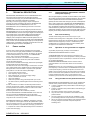
2.1.5
Vector control principles
What is vector control?
This is most easily explained by comparing with a DC motor.
In a DC motor, the magnetic field is
separately wound,
, so that the
armature current (torque)
) and field
current (flux) can be controlled
independently
of one another.
.
In an AC motor, the stator winding
currents define the flux and torque
so that it is extremely difficult to
separately control these parameters.
If the currents, which generate the
flux and torque, are separately
controlled, the output is optimized,
i.e. torque at zero speed, fast
response to load changes etc.
The current cannot be separately
controlled so that the magnitude
and phase – "the Vector" – of the
current must be controlled.
Supply
AC
drive inverter
Encoder
AC motor
Load
Position
feedback
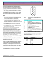
In order to control (closed-loop) the torque and flux in an AC motor, the magnitude
and phase of the stator winding current must be controlled, i.e. the vector quantity.
In order to control the phase, referred to the rotor, the rotor position must be
known. This means that for a complete vector control, an encoder must be used,
which signals the drive inverter the exact rotor position.
2.1.6
Sensorless vector control
However, for many applications, it is neither necessary to
use a pulse encoder nor is this justified for cost reasons.
If a drive inverter is to simulate the characteristics of a pulse
encoder, the software algorithm must precisely calculate the
rotor position and motor velocity. This is realized by
mathematically modeling the fundamental properties of the
motor.
To do this, the inverter must:
·
·
·
·
·
·
Monitor the output voltage and output current extremely
accurately.
Calculate the motor parameters (rotor, stator resistance,
leakage inductance, etc.)
Precisely simulate the thermal motor properties.
Adapt the motor parameters, taking into account the
particular operating conditions.
Carry-out mathematical calculations extremely quickly.
This has been realized using an ASIC which Siemens
developed:
The so-called Flash Floating Point Processor (F²P²; Fast
Floating Point Processor).
above, which can execute the millions of computations per
second in order to achieve the consistent high performance.
Thanks to this technology, a torque rise to 150% or more for
0.5 Hz and to over 200% for 2.5 Hz is obtained. A
consistently high performance is guaranteed over the
complete temperature range by using a model to adapt the
motor temperature.
The complete MICRO/MIDIMASTER Vector series has an
overload capability of 200% for 3 seconds. This means that
this drive inverter is especially suited for difficult applications,
for example cranes and lifts.
It is not necessary to compute the motor constants, as this is
realized automatically so that the user only has to set a gain
factor to adjust the drive inverter to a specific system inertia;
however, in many cases it isn't even necessary to change the
standard values entered in the factory.
2.1.7
Flash Floating Point Processor
The sensorless vector control is an extremely sophisticated
real-time control (closed-loop), which generally uses DSP or
RISC processors or multiple processors. The Siemens
solution relieves the microprocessor of time-consuming
routine tasks and the floating-point functions are
implemented in an customized ASIC. Control algorithms are
precisely implemented thanks to the floating-point function
without requiring ongoing re-scaling. Arithmetic overflows are
thus avoided, guaranteeing a consistent high accuracy. The
overall result is a reliable product with repeatable, dynamic
performance. The floating-point processor is implemented
using entirely combinatorial logic and achieves a
performance equivalent to 3 Mflops. The algorithm, used in
the MICRO/MIDIMASTER Vector is practically the same as
the algorithm that is used in the widely accepted
MASTERDRIVE series.
2.1.8
Benefits of sensorless vector control
·
Excellent speed control with integrated slip
compensation.
·
High torque at low speeds without any excessive boost
(breakaway torque).
·
Lower losses, higher efficiency.
·
Higher dynamic performance – improved response to
loads of different magnitudes.
·
Stable operation for large motors.
·
Improved performance at the current limit with improved
slip compensation.
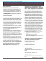
2.1.9
Vector operating range
Siemens, who pioneered this technology, has, for the first
time, integrated an almost closed-loop vector control without
pulse encoder in a standard product. This has been achieved
by using the Flash Floating Point Processor, explained
SIEMENS DA 64 – 2002/2003
2/3
Version D
TECHNICAL DESCRIPTION
MICROMASTER
MICROMASTER Vector
MIDIMASTER Vector
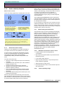
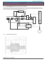
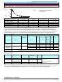
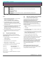
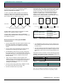
2.5
200
5
Frequency (Hz)
Constant current range
Constant current + orientation range
Fully-orientated Vector control
The above diagram illustrates the operating ranges of the
MICRO/MIDIMASTER Vector sensorless vector control.
Whereby the frequency range of the vector control lies
between 5Hz and 200Hz; V/Hz control is automatically
selected for values outside this range.
Constant current range
In this range, the drive inverter behaves just like a current
source and outputs the current value, programmed in parameter
P083, independent of the particular load.
For instance, for a 750 W motor, if P083 is set to 3.4 A then
the motor current remains independent of the motor load (full
or no load) at 3.4 A.
Constant torque (P078) and breakaway torque (P079) lie in
this range and offer a torque capability of up to 250 %.
This range is below approx. 5 Hz (while the output frequency
ramps-up from zero) and below 2.5 Hz (while the output
frequency ramps-down from a frequency above 5 Hz). The
2.5 Hz hysteresis bandwidth prevents oscillation between the
two operating modes. The specified 2.5 Hz and 5 Hz values
approximately correspond to 5 % or 10 % of the value,
programmed in P081 – the nominal rating plate frequency of
the motor.
Constant current and orientation range
When using the sensorless vector control (SVC, Sensorless
Vector Control), the data stamped on the rating plate of the
squirrel-cage induction motor must be precisely entered
(parameters P080 to P085). These parameters are set in the
factory to the data of a four-pole Siemens 1LA5 motor. This data
must be appropriately changed when using another motor. After
the SVC mode has been activated (P077=3), when the drive
inverter is powered-up the next time, the CAL message is
displayed for several seconds. During this time, the drive
inverter optimizes itself and computes the properties and
characteristics of the motor model, for example, the stator
resistance, leakage inductance, thermal time constant of the
rotor and stator.
The calibration routine (CALibration) must be
performed with the motor in a cold state. This is
because the drive inverter automatically compensates
for motor temperature changes.
SVC can only be used for induction motors and for single
motor drives or multi-motor drives with a mechanically
coupled load.
SVC cannot be used for:
·
Synchronous or reluctance motors
·
Multi-motor drives, group drives (where several motors
are connected in parallel at the output of the drive
inverter)
·
Motors with rated outputs less than half the rated drive
inverter output
·
Motors with a higher current demand than the drive
inverter can supply, i.e. IMotor > P083 max.
In cases such as these, a V/Hz characteristic must be
parameterized;
·
P077 = 0 for applications with linear torque
characteristics
·
P077 = 2 for applications with pump or fan
characteristics (square-law torque characteristics,
variable torque, VT).
The "Flying start" feature in both MICROMASTER Vector and
MIDIMASTER Vector depend on the vector algorithm and
therefore are subject to the same principles as for SVC
operation.
When operating in this range, and the output frequency is
being ramped-up, the back EMF of the motor establishes
itself. The system searches and locks onto the rotor speed
using this information. Once locked, it will remain locked until
the output frequency is reduced to below 2.5 Hz. The slip
compensation is also active in this range.
The restrictions, mentioned above, also apply to drive
inverters, which are configured for operation in the FCC
mode (Flux Current Control) (P077=1). This function was
kept in the vector range in order to guarantee downwards
compatibility with earlier MICRO and MIDIMASTER
generations.
Fully-orientated vector control
For MIDIMASTER, when a load with square-law torque
characteristic is connected, a significantly higher motor
current is permissible whereby, in almost all cases, the rated
output is achieved using the next larger motor (the motor
current can also be increased using parameter P083).
In this range, the drive inverter has determined the operating
state of the motor and maintains the frequency setpoint
within the operating range of the drive inverter. Deviations in
the ambient temperature, the stator resistance, motor slip
etc. are fully compensated over the complete load range and
beyond.
The sensorless vector control is a real, closed-loop control which
is highly dependent on the correctness of the data stamped on
the motor rating plate as well as the accuracy of the inverter's
current monitoring.
For a specific output, fan and pump drives can use a lowerrating drive inverter.
SIEMENS DA 64 – 2002/2003
Version D
2/4
TECHNICAL DESCRIPTION
MICROMASTER
MICROMASTER Vector
MIDIMASTER Vector
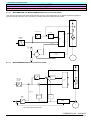
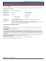
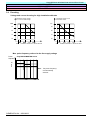
2.1.10
MICROMASTER and MICRO/MIDIMASTER Vector (in the V/Hz mode)
V/Hz control for single and multi-motor drives with asynchronous motors where there are no special requirements placed on
dynamic response. This is the case, for example, for pumps and fans and basic drives for slides.
Drive inverter
Vd
V/Hz characteristic
Vd- correction
V
V st
V*
f
Ramp-up/
ramp-down
generator
Gating
unit
f
n*
Open/close
H/W
current
trip
Inom (P083)
Current
sensing
I
M
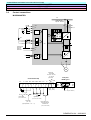
2.1.11
MICRO/MIDIMASTER Vector (in the FCC mode)
Vd
V/Hz characteristic
V
Vm
Ramp-up/
ramp-down
generator
n*
V*
_
f
Vd correction
V st
+
Gating
unit
+
+
-
f
+
Effective for
f > fs
Current
limiting
control
Slip
compensation
+
FCC
Current
sensing
_
I
Effective for f < sf
Iist
M
V/Hz control without speed sensing
SIEMENS DA 64 – 2002/2003
2/5
Version D
TECHNICAL DESCRIPTION
MICROMASTER
MICROMASTER Vector
MIDIMASTER Vector
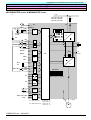
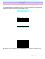
2.1.12
MICRO/MIDIMASTER Vector (sensorless vector control)
This control type is preferably used for single drives with asynchronous motors where the requirements placed on the dynamic
response range from low to high, and for speed control ranges up to 1:10. It is suitable for most industrial applications, for example,
extruders, packaging machines, industrial washing machines, lifts and cranes.
Drive inverter
EMF computer
for pre-control
¦
Iµ controller
I Start*
Ramp-up/
ramp-down
generator
n*
M
Acc.
dn*/dt
·
+
+
-
+
n controller
°··
·
Iµ*
+
+
M*
·
M*
¯
IW *
IW *
+
+
Coord
transformer
V*
V d-
V St
correction
gating
unit
α
Gating
unit
IW controller
f< fs
f
+
f>fs
+
Effective for f > fs
Iwist
I m ist
+
+
·
Load
control
Motor model
with vector
transformation
·
f
V
I
f slip
n calculated
M
2.1.13
Torque and speed response
SIEMENS DA 64 – 2002/2003
Version D
2/6
TECHNICAL DESCRIPTION
MICROMASTER
MICROMASTER Vector
MIDIMASTER Vector
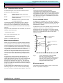
2.1.13.1 Features of different control techniques
Mode
V/Hz
Digital setpoint resolution
0.01
Analog setpoint resolution
10 bit
Internal frequency resolution
0.01
Speed accuracy
- constant torque
- field weakening range
Torque rise time
Torque ripple
SVC
>2 %
<2 % 1)
<5 % 1)
£1 %
fmax/fn ´ fslip/10 2)
» 50 ms
<25 ms
<10 ms
<2 %
<2 %
<2 %
1
) With slip compensation
2
) The slip values of standard motors are typically:
6 % at 1 kW, 3 % at 10 kW, 2 % at 30 kW, 1 % at 100 kW
2.2
FCC
Closed-loop PID control
All of the MICROMASTER Vector and MIDIMASTER Vector drive units have, as standard an integrated PID control, which uses the
second analog input as actual value signal input (0 - 10 V or 0 - 20 mA). This therefore provides an accuracy of 10 bit.
MICROMASTER has a closed-loop PI control which uses the digital input for the setpoint and the analog input for the actual value
signal. This function allows closed-loop control of quantities which only change slowly, for instance, temperature or pressure,
without requiring any additional circuitry or software. This means that closed-loop speed control is also possible for slow processes.
The reference value or setpoint is entered directly as a percentage of the controlled variable (0 - 100 %). This means that the
system is insensitive to measured quantities which are received from transducers. Examples of these transducers are, for example,
pressure and flow velocity. The signal, received from the transducer, is transferred to one of the analog inputs where it is compared
with the setpoint. The motor speed is then controlled so that the deviation between the setpoint and actual value is minimized.
Additional features of the PID control:
·
Any display scaling can be selected (P010, P001)
·
P, I and D factors can be separately defined
·
Selectable sampling interval and filtering
·
Can be flexibly adapted to the transducer signal
·
The motor can be shutdown below a minimum frequency – this can be parameterized (P220)
·
A message can be output at the minimum and maximum motor frequency – this can be selected using parameters (relay
output, P061 and P062).
Parameters P201 to P220 are assigned to the PID function.
SIEMENS DA 64 – 2002/2003
2/7
Version D
TECHNICAL DESCRIPTION
MICROMASTER
MICROMASTER Vector
MIDIMASTER Vector
2.3
causes the motor to be quickly braked and in a
controlled fashion. The energy fed back into the DC link
is converted into thermal energy by the motor using the
integrated braking chopper (P070 / P075) and an
external braking resistor for MICROMASTER Vector or
using the external brake module (EBU) and external
braking resistor options for MIDIMASTER Vector.
Shutting down (stopping) a motor
A drive can be shutdown in several ways:
·
·
·
Selecting OFF 1
(P051 to P055 or P356 = 1 or 2), this means that when
the ON command is reset, the drive inverter is
shutdown with the ramp-down time selected in P003.
Selecting OFF 2
(P051 to P055 or P356 = 4) means that the inverter is
inhibited and the motor coasts down.
Selecting OFF 3
(P051 to P055 or P356 = 5) means that the motor is
quickly braked. The motor is braked as quickly as
possible along the drive inverter current limit.
In addition to the three OFF commands, there are four
additional braking versions available.
·
Selecting an external brake
via the control relay outputs (P061 / P062 = 4)
·
Selecting DC current braking
means that the drive is quickly braked to standstill.
The DC current braking is activated using P073 with a
value greater than 0 and up to 200% (referred to P083).
This corresponds to approx. 30 - 40 % of the
regenerative braking. DC current braking is selected
using OFF 1 or externally via DIN 1 - DIN 6 (P051 P055 and P356 = 15). However, there is no defined
motor stop, as the brake is effective for the time,
parameterized in P003 and at a level, parameterized in
P073. Correspondingly, if the DC current brake is
activated using DIN1 - DIN6, it is activated as long as
there is a (HIGH) signal. The energy generated while
braking is discharged through the motor.
·
·
Selecting COMPOUND BRAKING™
is an effective method of stopping the motor in a
controlled fashion without the need for an external
braking resistor. The inverter controls this by impressing
a controlled amount of DC current into the motor
windings during ramp-down using a new software
modulation technique. COMPOUND BRAKING™ is
most effective at lower outputs where motor efficiencies
are their lowest. The compound brake is activated by
the magnitude of the braking current in P066 (greater 0
to 250%; referred to P083), and corresponds
approximately to 50 - 60 % of the effect of regenerative
braking. The energy generated is also discharged
through the motor. Compound braking is always
selected with the down ramp, i.e. as soon as a higher
setpoint change is made with respect to f = 0 or with
OFF 2 and OFF 3.
Comments:
It is not possible to combine the various braking
versions.
If OFF 2 or OFF 3 is selected, the ON command (OFF
1) must be reset, as otherwise the drive inverter would
go into the power-on inhibit condition if it was to be
powered-up again.
If compound braking is frequently used, this results in
a high motor temperature.
2.4
Emergency Off
General information
The following stop function categories are defined in
accordance with VDE 0113:
Category 0
Uncontrolled shutdown by immediately
disconnecting the power feed (the motor
coasts down).
Category 1
Controlled shutdown, whereby the power
remains connected in order to shutdown
the drive. The power feed is only
disconnected when the drive has come to a
standstill.
Category 2
Controlled shutdown, whereby the power
remains connected even after the drive has
come to a standstill.
For MICROMASTER, MICROMASTER Vector and
MIDIMASTER Vector, only Category 0 can be achieved
without using any external measures.
2.4.1
Safe standstill
This function has not been implemented in the
MICROMASTER, MICROMASTER Vector and
MIDIMASTER Vector.
The regenerative braking
SIEMENS DA 64 – 2002/2003
Version D
2/8
TECHNICAL DESCRIPTION
MICROMASTER
MICROMASTER Vector
MIDIMASTER Vector
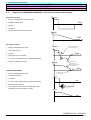
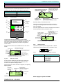
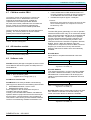
2.5
Diagrams of COMPOUND BRAKINGTM, DC current and regenerative braking
Regenerative braking
·
Energy is dissipated in an external resistor
·
Excellent braking torque
·
Smooth
·
Controlled
·
Speed is reduced linearly and smoothly
Torque
Time
Speed
Time
DC injection braking
·
Energy is dissipated in the motor
·
Poor braking torque
·
Smooth
·
Ramp-down is not controlled
·
30 - 40 % of the effectiveness of regenerative braking
·
There is no defined motor stop
Torque
Time until the motor flux
currents have decayed
Time
Speed
Rapid speed
decrease due to
peak braking torque at
low frequencies
Time
COMPOUND BRAKING™
·
Energy is dissipated in the motor
·
Good braking torque
·
Controlled
·
50 - 60 % of the effectiveness of regenerative braking
·
Speed is linearly reduced
·
Low speed fluctuations due to the oscillating torque –
depending on the load moment of inertia
The motor direction of rotation
can be reversed
Torque
Time
Speed
Time
SIEMENS DA 64 – 2002/2003
2/9
Version D
ENGINEERING INFORMATION AND INSTRUCTIONS
MICROMASTER
MICROMASTER Vector
MIDIMASTER Vector
3.
Engineering information and instructions
3.1
Technical comparison table
3/1
3.2
Dimensions and weights
3/2
3.3
Degrees of protection
3/5
3.4
Design guidelines
3/6
3.5
Line supply
3/7
3.6
Control connections
3/8
3.7
Recommended cable cross-sections
3/11
3.8
Maximum motor cable lengths
3/13
3.9
De-rating
3/15
3.10
Selection help for motors
3/17
3.11
Maintaining the EMC Directives
3/20
3.12
Line supply and output filters
3/22
3.13
Line harmonics and line impedance
3/34
3.14
Technical data for the line and output reactors
3/36
3.15
MICROMASTER braking resistors
3/47
3.16
Electronic braking module for MIDIMASTER
3/48
SIEMENS DA 64 – 2002/2003
Version D
3/0
ENGINEERING INFORMATION AND INSTRUCTIONS
MICROMASTER
MICROMASTER Vector
MIDIMASTER Vector
> empty page <
SIEMENS DA 64 – 2002/2003
3/1
Version D
ENGINEERING INFORMATION AND INSTRUCTIONS
MICROMASTER
MICROMASTER Vector
MIDIMASTER Vector
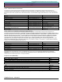
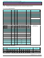
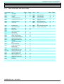
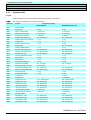
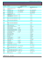
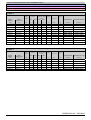
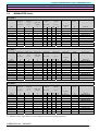
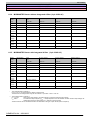
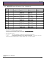
3.1 Technical comparison table
Power range
Voltage range
MICROMASTER 6SE92
MICROMASTER Vector 6SE32
MIDIMASTER Vector 6SE32
120 W - 3 kW, 230 V, 1 AC
120 W - 4 kW, 230 V, 3 AC
370 W – 7.5 kW, 400 V, 3 AC
208 - 240 V +/-10 %
380 - 500 V +/-10 %
120 W - 3 kW, 230 V, 1 AC
120 W - 4 kW, 230 V, 3 AC
370 W – 7.5 kW, 400 V, 3 AC
208 - 240 V +/-10 %
380 - 500 V +/-10 %
5.5 kW - 45 kW, 230 V, 3 AC
11 kW - 75 kW, 400 V, 3 AC
2.2 kW - 37 kW, 575 V, 3 AC
208 - 240 V +/-10 %
380 - 500 V +/-10 %
525 - 575 V +/-15 %
47-63Hz
cos F ³ 0.98, total l ³ 0.7
Max. 100.000 (guaranteed)
(5-sec. interval)
No higher than the nominal input
current
97 %
0 - 40 °C (50 °C without cover)
-40 to +70 °C
95 %, moisture condensation is not
permissible
IP20 / IP21 housing sizes A - 6
Clearance is not required
Housing size 7 = 100mm
IP56
= 150 mm
IP20 / IP21
= 100mm
IP56
= 150mm
IP20 / IP21
= 100mm
IP56
= 150mm
IP21/NEMA 1
(optional IP56/NEMA 4, also available)
Line supply frequency
Power factor
Power on/power off cycles
47-63Hz
cos F ³ 0.98, total l ³ 0.7
Max. 100.000 (guaranteed)
(5-sec. interval)
Inrush current
No higher than the nominal input
current
Inverter efficiency
97 %
Operating temperature
0 - 50 °C
Storage temperature
-40 to +70 °C
95 %, moisture condensation is not
Relative air humidity
permissible
Minimum lateral clearances No clearance is required
47-63Hz
cos F ³ 0.98, total l ³ 0.7
Max. 100.000 (guaranteed)
(5-sec. interval)
No higher than the nominal input
current
97 %
0 - 50 °C
-40 to +70 °C
95 %, moisture condensation is not
permissible
No clearance is required
Minimum clearances to the
top
100mm
100mm
Minimum clearances to the
bottom
100mm
100mm
Degree of protection
IP20/NEMA 1
(optional cable gland plate to meet
NEMA1 for Size A drive units)
Software-controlled fan cooling
0 - 400 Hz
0.05 Hz
IP20/NEMA 1
(optional cable gland plate to meet
NEMA1 for Size A drive units)
Software-controlled fan cooling
0 - 650 Hz
0.05 Hz
150% of the rated output current
for max. 60 s within 5min
150% of the rated output current for max. 60 s within 5min
200% rated output current for 3 s
SVC, FCC, V/Hz
SVC,FCC,V/Hz
6 (> 7.5 V = high, 33 V max.)
6 (> 7.5 V = high, 33 V max.)
0(2) - 10 V, 0/4 - 20 mA
0(2) - 10 V, 0/4-20 mA
-10 V/+10 V bipolar
-10 V/+10 V bipolar
10-bit resolution, differential input
10-bit resolution, differential input
0(2) - 10 V, 0(4) - 20 mA
0(2) - 10 V, 0/4) - 20 mA
PID input, 10-bit resolution
PID input, 10-bit resolution
0/4 - 20 mA
0/4 - 20 mA
with 500 W max. load
500 W max. load
10-bit resolution
10-bit resolution
Not available
0/4 - 20 mA
500W max. Last
30 V DC, 2 A; 240 V AC, 0.8 A
30 V DC, 2 A; 240 V AC, 0.8 A
changeover contact
changeover contact
30 V DC, 2 A; 240 V AC, 0.8 A
30 V DC, 2 A; 240 V AC, 0.8 A
NO contact
NO contact
Type D/terminal strip
Type D/terminal strip
Integrated
Optional, external module
Yes
Yes
Yes
Yes
Integrated PID control
Integrated PID control
Special PTC input
Special PTC input
I²t (UL certified)
I²t (UL certified)
Short-circuit protection, cable/ground
Short-circuit protection, cable/ground
Short-circuit protection, cable/cable
Short-circuit protection, cable/cable
Overtemperature protection
Overtemperature protection
Overvoltage protection
Overvoltage protection
Overcurrent protection
Overcurrent protection
Cooling
Output frequency
Output frequency
resolution
Overload capability
Control technique
Digital inputs
Analog input 1
V/Hz
3 (> 7.5 V = high, 33 V max.)
0 - 10 V/PI input
10-bit resolution, differential input
Analog input 2
Not available
Analog output 1
Not available
Analog output 2
Not available
Relay output 1
30 V DC, 1A; 110 V AC, 0.3 A,
NO contact
Not available
Relay output 2
RS485 interface
Braking chopper
Compound braking
Fast current limiting
Closed-loop PID control
Motor protection - external
Motor protection - internal
Drive inverter protection
Type D
Not available
Yes
Yes
Integrated PI control
PTC input at the digital input
I²t
Short-circuit protection, cable/ground
Short-circuit protection, cable/cable
Overtemperature protection
Overvoltage protection
Overcurrent protection
Fan cooling
0 - 650 Hz
0.05 Hz
SIEMENS DA 64 – 2002/2003
Version D
3/2
ENGINEERING INFORMATION AND INSTRUCTIONS
MICROMASTER
MICROMASTER Vector
MIDIMASTER Vector
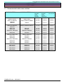
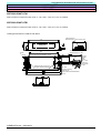
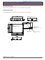
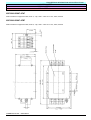
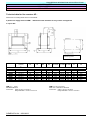
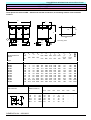
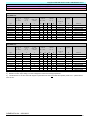
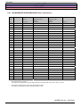
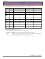
3.2 Dimensions and weights
B
MICROMASTER und MICROMASTER
Vector inverters must be mounted to a
suitable, flat surface using bolts, washers
and nuts.
F
DIN rail
H1
H
A
H1
H
Æ
Depth D
Two bolts are required for Size A drive
units. (M4)
Æ = 4.5 mm
T
B
Four bolts are required for Size B drive
units. (M4)
2 bolts M4
2 nuts M4
2 washers M4
Size A
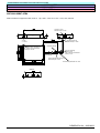
Four bolts are required for Size C drive
units. (M5)
B1
B
Æ
H1
H
B
H
Depth D
H1
Æ = 4.8 mm (B)
B
Size B:
4 bolts M4
4 nuts M4
4 washers M4
Size B
T
B1
B
H
C
H1
H1
Æ
H
Depth D
Æ = 5.6 mm (C)
B
Size C:
4 bolts M5
4 nuts M5
4 washers M5
T
Size C
Type
MM12
MM25
MM37
MM55
MM75
MM110
MM150
MM220
MM300
MM400
MM550
MM750
Table 1:
MMxxx
1-ph. 230 V
AC,
with filter,
Class A
MMxxx/2
1/3-ph. 230 V
AC,
without filter
MMxxx/3
3-ph. 400 - 500 V
AC, without filter
A
A
A
A
A
B
B
C
C
-
A
A
A
A
A
B
B
C
C
C
-
A
A
A
A
A
B
B
C
C
C
Housing dimensions (mm)
Size
Weight
H
W
D
H1
W1
F
(kg/lb)
A
175
x
73
X
141
160
-
55
0.8 / 1.8
B
184
x
149
X
172
174
138
-
2.6 / 5.7
C
215
x
185
X
195
204
174
-
5 / 11
MICROMASTER and MICROMASTER Vector sizes
SIEMENS DA 64 – 2002/2003
3/3
Version D
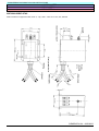
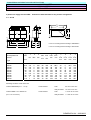
ENGINEERING INFORMATION AND INSTRUCTIONS
MICROMASTER
MICROMASTER Vector
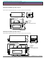
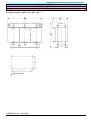
MIDIMASTER Vector
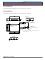
B
B1
H1
H
DepthD
H
Æ
Æ = 8,5mm
B
T
4 bolts M8
4 nuts M8
4 washers M8
Housingsizes4, 5and6
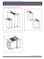
MIDIMASTER Vector – sizes 4, 5 and 6
Standard version:
IP21
Version with integrated filter:
IP20
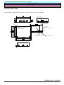
B
B1
H1
H
DepthD
H
Æ
Æ = 8,5mm
B
6 bolts M8
6 nuts M8
6 washers M8
Housingsize7
T
MIDIMASTER Vector - size 7
Standard version:
Version with integrated filter:
IP21
IP20
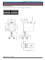
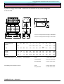
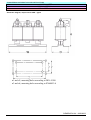
W1
H1
H
Depth D
Æ
Æ = 8.5 mm
W
Frame Sizes 4, 5 and 6
4 bolts M8
4 nuts M8
4 washers M8
(6 bolts M8 – size 7)
(6 nuts M8 – size 7)
(6 washers M8 – size 7)
MIDIMASTER Vector - sizes 4, 5, 6 and 7 in degree of protection IP56
SIEMENS DA 64 – 2002/2003
Version D
3/4
ENGINEERING INFORMATION AND INSTRUCTIONS
MICROMASTER
MICROMASTER Vector
MIDIMASTER Vector
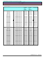
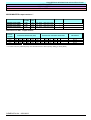
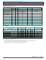
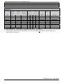
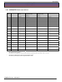
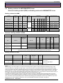
MIDIMASTER Vector
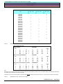
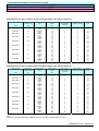
Table 2:
Size
Type
3-ph. 208 – 240 V
AC
3-ph. 400 – 500 V
AC
MDV220/4
MDV400/4
MDV550/2
MDV550/4
MDV750/2
MDV750/3
MDV750/4
MDV1100/2
MDV1100/3
MDV1100/4
MDV1500/2
MDV1500/3
MDV1500/4
MDV1850/2
MDV1850/3
MDV1850/4
MDV2200/2
MDV2200/3
MDV2200/4
MDV3000/2
MDV3000/3
MDV3000/4
MDV3700/2
MDV3700/3
MDV3700/4
MDV4500/2
MDV4500/3
MDV5500/3
MDV7500/3
4
5
5
6
6
6
7
7
7
-
4
4
5
5
6
6
6
7
7
7
3-ph. 525 – 575 V
AC
4
4
4
4
4
5
5
6
6
6
-
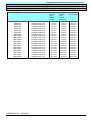
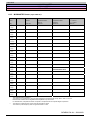
MIDIMASTER Vector - sizes
Drive unit dimensions (mm)
Standard version:
Size
H
W
X
275
x
450
4
x
275
x
550
5
x
275
x
650
6
x
420
x
850
7
Version with integrated EMC filter:
Size
H
W
4
700
x
275
X
5
800
x
275
x
6
920
x
275
x
7
1150
x
420
x
Version with increased degree of protection:
Size
H
W
4
675
x
360
X
5
775
x
360
x
875
x
360
x
6
7
1150
x
500
x
IP21/NEMA 1
D
H1
430
210
530
210
630
285
830
310
IP20/NEMA 1
W1
255
255
255
400
Weight
kg
11
15
27
56
D
H1
210
680
210
780
285
900
310
1130
IP56/NEMA 4/12
W1
255
255
255
400
Weight
kg
19
24
39
90
D
351
422
483
570
W1
313
313
313
553
Weight
kg
30
40
54
100
H1
655
755
855
1130
Note:
Dimension "D" for drive units with degree of protection IP21 and IP20 includes the operator panel. If an OPM2 operator panel with plain text display,
is installed, then an additional 30 mm will be required.
Dimension “D” for drive units with degree of protection IP56 does not includes the front panel access door - add 25 mm to include this extra depth.
Table 3:
MIDIMASTER Vector – dimensions and weights
SIEMENS DA 64 – 2002/2003
3/5
Version D
ENGINEERING INFORMATION AND INSTRUCTIONS
MICROMASTER
MICROMASTER Vector
MIDIMASTER Vector
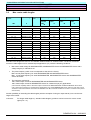
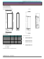
3.3 Degrees of protection
The IP number defines the
degree of protection against the
ingress of dirt, foreign bodies,
water etc. (Ingress Protection;
IP) for the associated drive
inverter.
First number
0 No specific protection
1 Protected against solid
0 No specific protection
1 Protected against water falling
MICROMASTER and
MICROMASTER Vector have
degree of protection IP20 (this
corresponds to the US NEMA 1
Class).
objects with a diameter of 50
mm
vertically
1 Protected
2 Protected against solid
2 Protected against vertically
falling spray water if the equipment
is tipped up to 15 degrees to the
vertical
against impact up
to 0.225 J
MIDIMASTER Vector models
with degree of protection IP21
(this corresponds to the US
NEMA 1 Class) or IP56 (this
corresponds to the US NEMA
4/12 Class).
3 Protected against solid
objects with a diameter larger
or equal to 2.5 mm
The significance of the
individual IP class numbers
referred to the protection
against the ingress of dirt etc. is
explained in Table 4:
Second number
IPXxx
objects with a diameter larger
or equal to 12 mm
IpxXx
3 Protected against vertically
Third number
(not specified)
IPxxX
0 No specific
protection
2 Protected
against impact up
to 0.375 J
3 Protected
4 Protected against solid
objects with a diameter larger
or equal to 1 mm
falling spray water if the equipment
is tipped up to 60 degrees to the
vertical
4 Protected against water sprayed
from all directions
5 Protected
5 Protected against dust
(limited ingress)
5 Protected against low-pressure
water jets from all directions
7 Protected
6 Protected against dust
6 Protected against low-pressure
(totally)
water jets from all directions
7 Protected against immersion
between 15 cm and 1 m
8 Protected against immersion
under pressure
against impact up
to 0.5 J
against impact up
to 2.0 J
against impact up
to 6.0 J
9 Protected
against impact up
to 20.0 J
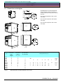
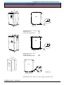
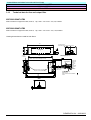
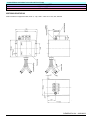
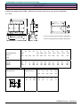
Rear cabinet panel
Fig. 2:
MIDIMASTER Vector with degree of protection IP56 – installed in a housing
MIDIMASTER Vector, with degree of protection IP56/NEMA 4/12, can be accommodated in a larger housing, whereby the heatsink
protrudes through the rear cover of the unit. This ensures that the heat from the drive inverter is dissipated to the ambient air
without the need for additional cooling fans. This guarantees the IP56 degree of protection. Only the minimum mounting clearance
of 150mm to the next drive unit must be observed.
SIEMENS DA 64 – 2002/2003
Version D
3/6
ENGINEERING INFORMATION AND INSTRUCTIONS
MICROMASTER
MICROMASTER Vector
MIDIMASTER Vector
Supply
Separate filter
Metal
mounting plate
Retain the motor and control
cables to the metal plate
using suitable clamps
.
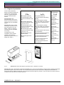
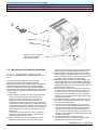
3.4 Mounting and installation guidelines
Fig. 3.11.3
Wiring guidelines to optimize the noise
immunity of MICROMASTER and MICROMASTER Vector,
Size C
The drive inverters are designed for use in industrial
environments with strong electromagnetic noise and
disturbances. Generally, safe, reliable and fault-free operation is
guaranteed if the drive units have been correctly installed.
However, if problems do occur, then the following guidelines
might possibly help. It can be especially effective to connect the
drive inverter ground potential, as subsequently described, to 0
V of the system.
(1) Ensure that all of the drive units are correctly grounded
using a short grounding cable with adequate crosssection, to a common neutral point or a busbar. It is
especially important that all of the control devices,
connected to the drive inverter (for example, a PLC) are
connected to the same grounding or neutral point through
a short grounding cable with adequate cross-section. Flat
conductors are preferred (for example, finely-stranded or
metal brackets), as they have a low impedance at high
frequencies.
If motors are fed from the drive inverter, the potential
bonding conductor should be directly connected to 0 V
(PE) of the particular drive inverter.
(2) Remove the paint from the mounting plate in order to
establish a good electrical connection between the
(3)
(4)
(5)
(6)
(7)
(8)
heatsink and the housing. Please use serrated washers
when mounting and installing MIDIMASTER Vector.
When possible, use shielded cables to connect-up the
control terminals. Assemble the cable ends correctly so
that non-shielded wires and conductors are kept as short
as possible. Where possible, use cable glands.
Separately route the control cable, as far as possible, away
from the supply cable. This can be realized, for example, by
using separate cable ducts. If control cables and line supply
cables (power cables) cross over, then arrange the cables so
that they cross at an angle of 90°.
Ensure that the contactors in the electrical cabinet are
provided with noise suppression devices. For AC coils,
use RC elements or for DC coils, use free-wheeling
diodes. Varistors are also effective. This is especially
important if the contactors are controlled using the drive
inverter relay connection.
Use shielded cables to connect-up the motors or route
the cables in a protective pipe and ground the shield at
both ends using cable glands.
If the drive inverters are installed in an environment
which is prone to electromagnetic disturbances, then a
noise suppression filter should be used to dampen the
cable-borne and radiated noise and disturbances. In
order to guarantee optimum operating conditions, there
should be a good electrical connection between the filter
and the mounting plate.
If a line-side EMC filter and line reactor are
simultaneously used, the EMC filter must be located
between the drive inverter and line reactor.
SIEMENS DA 64 – 2002/2003
3/7
Version D
ENGINEERING INFORMATION AND INSTRUCTIONS
MICROMASTER
MICROMASTER Vector
MIDIMASTER Vector
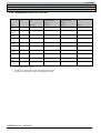
3.5 Line supply
The drive inverters are designed for limit values defined in the following standards. These standards describe the noise voltages
permissible at the line supply input.
IEC/EN 61000-4-4:
(VDE 0847 Part 4-4)
Brief voltage spikes/noise pulses:
4 kV
IEC/EN 61000-4-5:
(VDE 0847 Part 4-5)
Surge voltages:
4 kV common mode
2 kV differential mode
IEC/EN 61000-4-11:
(VDE 0847 Part 4-11)
Voltage dips:
30 % for 60 ms
10 % for 100 ms
Voltage interruptions:
>95 % for 5 s
Voltage fluctuations:
Vrated +/-10 %
IEC/EN 61000-2-4:
(VDE 0839 Part 2-4)
Level of compatibility for low-frequency, cable-borne noise in industrial systems and plants,
Class 3, 10 % distortion factor (THD)
EN 61000-3-2
Limit values for harmonic currents (drive unit incoming current <= 16 A per phase)
st
Since the 1 of January 2001, all electrical equipment, where the EMC Directive applies, must be in full
compliance with EN 61000-3-2. (refer to Section 1.3.3)
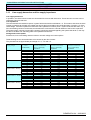
Line harmonics and line impedance
Line harmonics
When operational, drive inverters cause non-sinusoidal line currents with harmonics. The harmonic currents can be
reduced by additionally using line reactors.
Line impedance
The ratio between the rated drive power / line supply fault level should not fall below 1 %. This means, that when the
drive inverter is operating at full load, the voltage drop across the line impedance should be greater than or equal to
1% of the rated voltage. If the line impedance is below this value (rated drive inverter power / line supply fault level
less than 1%), a line-commutating reactor must be used, as otherwise this could result in a shorter lifetime of the DC
link capacitors.
The power supply company (power utility company) should be contacted regarding the line supply fault level. This may
also be able to be taken from the rating plate of the upstream transformer.
Voltage and current spikes
Furthermore, line-commutating reactors reduce or smooth voltage and current spikes.
(further details are provided in Section 3.14, Line reactors)
SIEMENS DA 64 – 2002/2003
Version D
3/8
ENGINEERING INFORMATION AND INSTRUCTIONS
MICROMASTER
MICROMASTER Vector
MIDIMASTER Vector
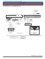
3.6
Control connections
MICROMASTER:
PE
1/3-ph. 230 V AC
3-ph. 380 - 500 V AC
³ 4,7 k W
V: 0 - 10 V
2 - 10 V or
AIN+
AIN-
L/L1, N/L2
or
L/L1, N/L2, L3
PE
+10 V
1
SI
0V
2
3
AD
4
~
Jog
P
–
24 V
+
RS485
DIN1
DIN2
5
DIN3
6
or
7
Power supply for
actual value
sensing or
another load
CPU
+15 V
8
0V
9
RL1
RL1B
10
RL1C
11
3
PE
~
U, V, W
M
Output relay
(NO contact)
max. 0.3 A/ 110 V AC,
1 A/ 30 V DC
(ohmic load)
Control terminal strip
P10+
0V
1
2
AEIN+ AEIN- DEIN1 DEIN2 DEIN3
3
4
5
6
7
P15+
0V
8
9
10
11
RL1B RL1C
(NO) (COM )
Front panel
RS485, type D
1
5
9
6
0V
B/P
A/N
Power supply
(+10 V, max. 10 mA )
Analog input
(0/2 - 10 V)
(input impedance = 70 k
5 V (max. 250 mA )
Digital inputs
(7.5 - 33 V, max. 5 mA)
W)
Power supply for PI
actual value sensing
or another load
(+15 V, max. 50 mA)
SIEMENS DA 64 – 2002/2003
3/9
Version D
ENGINEERING INFORMATION AND INSTRUCTIONS
MICROMASTER
MICROMASTER Vector
MIDIMASTER Vector
MICROMASTER Vector & MIDIMASTER Vector
8
PE
3-ph. 208 - 230 V AC
3-ph. 380 - 500 V AC
3-ph. 525 - 575 V AC
³4.7kW
V: (±) 0 - 10 V or
2 - 10 V
AIN1+
AIN1-
–
0V
2
3
AD
4
I: 0 - 20 mA or
4 - 20 mA
L1, L2, L3
PE
+10 V
1
SI
Jog
~
P
24 V
+
RS485
DIN1
DIN2
5
DIN3
DIN4
6
DC+
8
9
AIN2/PID+
EBE
7
10
DC-
+15 V
AD
BCPU
AIN2/PID-
Only for MMV
11
A1OFF+
AOFF-
12
DA
13
Motor
PTC
3~
14
DIN5
15
DIN6
16
DIP switch
17
RL1
18
1
19
2
3
4
5
6
(Note: Switch 6 is not assigned)
20
RL2
21
22
23*
N-
24
P+
25
26*
A2OFF+ (only for MD)
AOFF-
27
+5 V
RS485
PE
DA
13
*for MIDIMASTER:
Terminal 23 +5V
Terminal 26 PE
*for MICROMASTER:
Terminal 23 PE
Terminal 26 +5V
PE
U, V, W
M
SIEMENS DA 64 – 2002/2003
Version D
3/10
ENGINEERING INFORMATION AND INSTRUCTIONS
MICROMASTER
MICROMASTER Vector
MIDIMASTER Vector
MICROMASTER Vector & MIDIMASTER Vector
Output relay
max. 2,0 A/110 V AC
0.8 A/ 240 V AC( overvoltage Cat. 2 )
or 2 A/ 30 V DC
(ohmic load)
P10+
1
0 V AEIN+ AEIN- DEIN1 DEIN2 DEIN3 DEIN4 P15+PIDEIN+ PIDEIN-
2
3
4
5
6
7
8
9
10
11
AAUS+ AAUS- PTC
12
13
14
PTC DEIN5 DEIN6
15
16
17
18
19
21
20
22
RL1A RL1B RL1C RL2B RL2C
(NC) (NO) (COM) (NO) (COM)
Power supply
(+10 V, max. 10 mA)
Digital inputs
(7.5 - 33 V, max. 5 mA)
Analog input 1
-10 V to+10 V
0/2 Þ 10 V
(input impedance 70 k W)
or
0/4 Þ 20 mA
(resistance = 300 W)
23*
24
25
Analog input 2
0Þ10 V
or
0Þ20 mA
Power supply for
PID actual value sensing
or other loads
(+15 V, max. 50 mA)
Analog output
0/4 - 20 mA
(500 W load)
Digital inputs
(7.5 - 33 V, max.5mA)
Input for motor temp. protection
Note: For PTC motor temp.
protection, P087 = 1
1
5
9
26*
6
P+
0V
NPE
P+
N-
RS485
(for USS protocol)
5 V (max. 250 mA)
P5V+
Control terminals
Front panel
RS485, type D
Caution: Terminals 23 and 26 have different functions for MICROMASTER Vector and MIDIMASTER Vector.
*for MIDIMASTER Vector:
Terminal 23 +5V
Terminal 26 PE
*for MICROMASTER Vector: Terminal 23 PE
Terminal 26 +5V
SIEMENS DA 64 – 2002/2003
3/11
Version D
ENGINEERING INFORMATION AND INSTRUCTIONS
MICROMASTER
MICROMASTER Vector
MIDIMASTER Vector
3.7 Recommended cable cross-sections
MICROMASTER Vector
MICROMASTER Basic
MMV12; MMV25; MMV37
MMV55; MMV75
MMV110; MMV150;
MMV220
MMV300
MM12; MM25; MM37;
MM55; MM75
MM110; MM150; MM220
Recommended cable
crosssection,
line side
1.0 mm²
1.5 mm²
2.5 mm²
MM300
4.0 mm²
2.5 mm²
4.0 mm²
MMV12/2; MMV25/2;
MMV37/2 MMV55/2;
MMV75/2
MMV110/2
MMV150/2
MMV220/2; MMV300/2
MM12/2; MM25/2;
MM37/2; MM55/2; MM75/2
1.0 mm²
1.0 mm²
1.0 mm²
1.0 mm²
4.0 mm²
4.0 mm²
MM110/2;
MM150/2
MM220/2; MM300/2
1.5 mm²
2.5 mm²
2.5 mm²
1.5 mm²
1.5 mm²
2.5 mm²
4.0 mm²
4.0 mm²
4.0 mm²
MMV400/2
MM400/2
4.0 mm²
2.5 mm²
4.0 mm²
MMV37/3; MMV55/3;
MMV75/3; MMV110/3
MMV150/3
MMV220/3
MMV300/3; MMV400/3;
MM37/3; MM55/3;
MM75/3; MM110/3
MM150/3
MM220/3
MM300/3; MM400/3
1.0 mm²
1.0 mm²
1.5 mm²
1.5 mm²
2.5 mm²
1.0 mm²
1.0 mm²
1.0 mm²
1.5 mm²
1.5 mm²
4.0 mm²
4.0 mm²
4.0 mm²
4.0 mm²
4.0 mm²
MMV550/3
MMV750/3
MM550/3
MM750/3
2.5 mm²
4.0 mm²
2.5 mm²
2.5 mm²
4.0 mm²
4.0 mm²
MMV220/3F
MMV300/3F
MMV400/3F
MM220/3F
MM300/3F
MM400/3F
1.5 mm²
1.5 mm²
2.5 mm²
1.0 mm²
1.5 mm²
1.5 mm²
4.0 mm²
4.0 mm²
4.0 mm²
MMV550/3F
MMV750/3F
MM550/3F
MM750/3F
2.5 mm²
4.0 mm²
2.5 mm²
2.5 mm²
4.0 mm²
4.0 mm²
Recommend- Max. cable
ed cable
cross section
crosssection,
motor side
1.0 mm²
4.0 mm²
1.0 mm²
4.0 mm²
1.5 mm²
4.0 mm²
SIEMENS DA 64 – 2002/2003
Version D
3/12
ENGINEERING INFORMATION AND INSTRUCTIONS
MICROMASTER
MICROMASTER Vector
MIDIMASTER Vector
MIDIMASTER Vector
Torque application
MDV550/2
MDV550/2
MDV750/2
MDV750/2
MDV1100/2
MDV1100/2
MDV1500/2
MDV1500/2
MDV1850/2
MDV1850/2
MDV2200/2
MDV2200/2
MDV3000/2
MDV3000/2
MDV3700/2
MDV3700/2
MDV4500/2
MDV4500/2
Constant torque (CT)
Variable torque (VT)
Constant torque (CT)
Variable torque (VT)
Constant torque (CT)
Variable torque (VT)
Constant torque (CT)
Variable torque (VT)
Constant torque (CT)
Variable torque (VT)
Constant torque (CT)
Variable torque (VT)
Constant torque (CT)
Variable torque (VT)
Constant torque (CT)
Variable torque (VT)
Constant torque (CT)
Variable torque (VT)
Recommended cable
crosssection,
line side
6.0 mm²
6.0 mm²
10.0 mm²
10.0 mm²
16.0 mm²
----------25.0 mm²
25.0 mm²
35.0 mm²
35.0 mm²
35.0 mm²
35.0 mm²
70.0 mm²
70.0 mm²
95.0 mm²
95.0 mm²
95.0 mm²
-----------
MDV750/3
MDV750/3
MDV1100/3
MDV1100/3
MDV1500/3
MDV1500/3
MDV1850/3
MDV1850/3
MDV2200/3
MDV2200/3
MDV3000/3
MDV3000/3
MDV3700/3
MDV3700/3
MDV4500/3
MDV4500/3
MDV5500/3
MDV5500/3
MDV7500/3
MDV7500/3
Constant torque (CT)
Variable torque (VT)
Constant torque (CT)
Variable torque (VT)
Constant torque (CT)
Variable torque (VT)
Constant torque (CT)
Variable torque (VT)
Constant torque (CT)
Variable torque (VT)
Constant torque (CT)
Variable torque (VT)
Constant torque (CT)
Variable torque (VT)
Constant torque (CT)
Variable torque (VT)
Constant torque (CT)
Variable torque (VT)
Constant torque (CT)
Variable torque (VT)
6.0 mm²
6.0 mm²
6.0 mm²
6.0 mm²
10.0 mm²
10.0 mm²
16.0 mm²
16.0 mm²
25.0 mm²
25.0 mm²
35.0 mm²
35.0 mm²
35.0 mm²
35.0 mm²
50.0 mm²
50.0 mm²
70.0 mm²
70.0 mm²
95.0 mm²
95.0 mm²
Recommend- Max. cable
ed cable
cross section
crosssection,
motor side
4.0 mm²
16.0 mm²
6.0 mm²
16.0 mm²
6.0 mm²
35.0 mm²
6.0 mm²
35.0 mm²
10.0 mm²
35.0 mm²
--------------------16.0 mm²
35.0 mm²
16.0 mm²
35.0 mm²
16.0 mm²
35.0 mm²
16.0 mm²
35.0 mm²
25.0 mm²
35.0 mm²
35.0 mm²
35.0 mm²
50.0 mm²
95.0 mm²
70.0 mm²
95.0 mm²
70.0 mm²
95.0 mm²
95.0 mm²
95.0 mm²
95.0 mm²
95.0 mm²
--------------------4.0 mm²
4.0 mm²
4.0 mm²
6.0 mm²
6.0 mm²
6.0 mm²
10.0 mm²
10.0 mm²
10.0 mm²
16.0 mm²
16.0 mm²
25.0 mm²
25.0 mm²
25.0 mm²
50.0 mm²
50.0 mm²
70.0 mm²
70.0 mm²
95.0 mm²
95.0 mm²
16.0 mm²
16.0 mm²
16.0 mm²
16.0 mm²
35.0 mm²
35.0 mm²
35.0 mm²
35.0 mm²
35.0 mm²
35.0 mm²
35.0 mm²
35.0 mm²
35.0 mm²
35.0 mm²
95.0 mm²
95.0 mm²
95.0 mm²
95.0 mm²
95.0 mm²
95.0 mm²
SIEMENS DA 64 – 2002/2003
3/13
Version D
ENGINEERING INFORMATION AND INSTRUCTIONS
MICROMASTER
MICROMASTER Vector
MIDIMASTER Vector
MIDIMASTER Vector
Torque application
MDV220/4
MDV220/4
MDV400/4
MDV400/4
MDV550/4
MDV550/4
MDV750/4
MDV750/4
MDV1100/4
MDV1100/4
MDV1500/4
MDV1500/4
MDV1850/4
MDV1850/4
MDV2200/4
MDV2200/4
MDV3000/4
MDV3000/4
MDV3700/4
MDV3700/4
Constant torque (CT)
Variable torque (VT)
Constant torque (CT)
Variable torque (VT)
Constant torque (CT)
Variable torque (VT)
Constant torque (CT)
Variable torque (VT)
Constant torque (CT)
Variable torque (VT)
Constant torque (CT)
Variable torque (VT)
Constant torque (CT)
Variable torque (VT)
Constant torque (CT)
Variable torque (VT)
Constant torque (CT)
Variable torque (VT)
Constant torque (CT)
Variable torque (VT)
Recommended cable
crosssection,
line side
1.5 mm²
1.5 mm²
1.5 mm²
1.5 mm²
2.5 mm²
2.5 mm²
4.0 mm²
4.0 mm²
4.0 mm²
4.0 mm²
6.0 mm²
6.0 mm²
10.0 mm²
10.0 mm²
10.0 mm²
10.0 mm²
16.0 mm²
16.0 mm²
25.0 mm²
25.0 mm²
Recommend- Max. cable
ed cable
cross section
crosssection,
motor side
1.5 mm²
16.0 mm²
1.5 mm²
16.0 mm²
1.5 mm²
16.0 mm²
1.5 mm²
16.0 mm²
1.5 mm²
16.0 mm²
1.5 mm²
16.0 mm²
2.5 mm²
16.0 mm²
2.5 mm²
16.0 mm²
4.0 mm²
16.0 mm²
4.0 mm²
16.0 mm²
4.0 mm²
35.0 mm²
4.0 mm²
35.0 mm²
6.0 mm²
35.0 mm²
6.0 mm²
35.0 mm²
10.0 mm²
35.0 mm²
10.0 mm²
35.0 mm²
10.0 mm²
35.0 mm²
10.0 mm²
35.0 mm²
16.0 mm²
35.0 mm²
16.0 mm²
35.0 mm²
SIEMENS DA 64 – 2002/2003
Version D
3/14
ENGINEERING INFORMATION AND INSTRUCTIONS
MICROMASTER
MICROMASTER Vector
MIDIMASTER Vector
3.8
Max. motor cable lengths
Drive inverter
power
Rated voltage
KW
Housing
size
V
Without output reactor
With output reactor
Nonshielded
cable
M
Non-shielded
cable
M
Shielded
cable
m
Shielded
cable
m
MICROMASTER / MICROMASTER Vector
0.12 - 1.5
208-240 ±10%
A, B
200
200
250
225
2.2 – 4.0
208-240 ±10%
C
185
150
235
185
0.37 - 1.5
380-500 ± 10%
A
110
80
185
125
2.2 – 3.0
380-500 ± 10%
B
170
140
220
170
4.0 - 7.5
380-500 ± 10%
C
200
200
300
250
MIDIMASTER Vector
5.5
208-240 ±10%
4
200
50
250
80
7.5 - 11
208-240 ±10%
4, 5
300
200
350
225
15 - 22
208-240±10%
6
300
300
350
325
30 - 45
208-240±10%
7
300
300
350
325
7.5 - 18.5
380-500± 10%
4, 5
150
75
200
100
22 - 37
380-500± 10%
6
200
150
250
175
45 - 75
380-500 ± 10%
7
300
300
350
325
2.2 - 18.5
525-575 ± 10%
4,5
100
100
150
125
22 - 37
525-575 ± 10%
6
150
150
200
175
Standard cable lengths are 50m for non-shielded cables and 25m for shielded cables. The above mentioned
maximum cable lengths are for constant torque applications (CT) under the following conditions:
·
Max. 460 V rated voltage for MICROMASTER, MICROMASTER Vector and MIDIMASTER Vector with a
voltage range 3-ph. 380-500 V AC.
·
The pulse frequency which is set corresponds to that set in the factory:
Max. 16 kHz pulse frequency for 230V MICROMASTER and MICROMASTER Vector
Max. 4 kHz pulse frequency for 400V MICROMASTER, MICROMASTER Vector and all MIDIMASTER
Vector drive units
·
The maximum overload is:
150% rated output current for MICROMASTER and MICROMASTER Vector
150% rated output current for MIDIMASTER Vector for constant torque (CT) applications
(The overload capability refers to the rated output currents of the MICROMASTER and MICROMASTER Vector drive
units, rated output currents for constant torque applications (CT) of the MIDIMASTER Vector and for a load duty cycle of
5 minutes. This means that the drive units can withstand a of 50% overload condition for a total of 1 minute over a period
of 5 minutes.)
Another possibility of extending the cable lengths (with the exception of using an output reactor) is to use the next
larger drive inverter.
Comment:
For longer cable lengths (> standard cable lengths), problems can be incurred for vector control
types (P77 = 3).
SIEMENS DA 64 – 2002/2003
3/15
Version D
ENGINEERING INFORMATION AND INSTRUCTIONS
MICROMASTER
MICROMASTER Vector
MIDIMASTER Vector
3.9 De-rating
Voltage and current de-rating for high installation altitudes
Permissible supply voltage
as a % of the rated voltage
Permissible current as a %
of the rated current
100
100
90
90
80
80
70
70
60
60
1000
4000
2000
3000
500
Installation altitude in m above sea level
2000
3000
1000
4000
500
Installation altitude in m above sea level
Max. pulse frequency referred to the line supply voltage
Pulse
frequency
Only MICROMASTER Vector
16
8
4
2
Note: The pulse frequency
is automatically
reduced
0
480
540
SIEMENS DA 64 – 2002/2003
Version D
3/16
ENGINEERING INFORMATION AND INSTRUCTIONS
MICROMASTER
MICROMASTER Vector
MIDIMASTER Vector
Maximum output current referred to the pulse frequency
As a result of higher switching losses at increased switching frequencies, the maximum continuous current (100 %) of some drive inverters
can be reduced, if a pulse frequency other than the standard pulse frequency is selected.
Type
Note:
Perm. load as a % of the
max. continuous current
at 16 kHz
at 8 kHz
MMV75/3
80
100
MMV110/3
50
80
MMV150/3
50
80
MMV220/3
80
100
MMV300/3
50
80
MMV400/3
50
80
MMV550/3
50
80
MMV750/3
50
80
If the pulse frequency is either 2 or 4 kHz, the above mentioned drive inverters are not de-rated.
Type
Perm. load as a % of the
max. continuous current
at 16 kHz
at 8 kHz
MDV550/2
39
75
MDV750/2
64
90
MDV1100/2
55
75
MDV1500/2
38
68
MDV1850/2
43
79
MDV2200/2
38
68
MDV750/3
55
100
MDV1100/3
39
75
MDV1500/3
64
90
MDV1850/3
55
75
MDV2200/3
40
75
MDV3000/3
47
88
MDV3700/3
40
75
MDV550/4
75
100
MDV750/4
55
100
MDV1100/4
39
75
MDV1500/4
64
90
MDV1850/4
55
75
Note: For all other Size 6 drive inverters, 575 V and Size 7 MIDIMASTER Vector, the pulse frequency can either be 2 or 4 kHz.
SIEMENS DA 64 – 2002/2003
3/17
Version D
ENGINEERING INFORMATION AND INSTRUCTIONS
MICROMASTER
MICROMASTER Vector
MIDIMASTER Vector
3.10
Selection aid for motors
A detailed description of the motors and selection tables is
provided in the following Catalogs:
M 11:
Three-phase low-voltage squirrel-cage
induction motors
DA 47:
Reluctance motors: Synchronous motors for
variable-speed drives
DA 48:
SIEMOSYN motors: Synchronous motors
for variable-speed drives
The technical guidelines, specified here, refer to Siemens
1LA5, 1LA6 and 1LA7 low-voltage motors as well as the
Siemens 1LA5 force-ventilated motors. If third-party motors
are used, then their specific technical data must be carefully
observed.
All types of load characteristics are conceivable; only the most
important are discussed here:
- constant-torque drives
Hz.
The assignment tables indicate that Siemens
1LA5/1LA6/1LA7 low-voltage motors can be generally
operated with 100% rated torque if they are utilized according
to temperature rise Class F in a 1:2 control range. If they are
operated in accordance with temperature rise Class B, then,
for 1LA5/1LA6/1LA7 motors, the permissible torque must be
reduced by approx. 10%.
Force-ventilated motors:
In addition to non-ventilated 1LA5, 1LA6 and 1LA7 motors,
force-ventilated 1LA5/1LA7 motors can be used. According to
Fig. 1, the permissible S1 torque at the rated frequency can
be used down to standstill.
It makes sense to use force-ventilated motors if a high torque
utilization is required, even at the lowest speeds.
Standard motors with pole numbers > 4 should be operated
with speeds > approx. 2200 RPM (e.g. in the field-weakening
range). For non-ventilated motors, the fan noise can be
reduced in this way.
If M = const. ("Constant torque", CT)
- blower and pump drives
M/M
n
%
with M ~ n² ("Variable torque", VT).
Motor torque utilization:
Which motor is best suited for a specific application depends
on its permissible torque characteristic over the speed range.
Typical characteristics for the continuous permissible torque
of a non-ventilated motor with a rated frequency of 50 Hz are
shown in Fig. 1. The torque which can be used at low speeds
is significantly lower than that at 50 Hz due to the lower
cooling effect. The torque reduction factor is not the same for
all motors. The assignment tables below specify the torque
reduction as a function of the speed in the frequency range
f = 0 Hz to 50 Hz when utilized according to temperature rise
Class F.
For frequencies, which lie above the rated frequency fn, the
voltage remains the same if the maximum drive inverter
output voltage has been reached. The motor is operated with
field weakening in this range. The torque, which can be
thermally used, decreases with approx. fn/f. The stall torque
2
decreases as a function of (fn/f) which means that the safety
margin to the stall torque decreases and the load capability of
the drive decreases.
For MICROMASTER and MIDIMASTER drives with a fieldweakening range of f = 50 Hz to 100 Hz, the load capability
for 1LA5, 1LA6 and 1LA7 motors drops to approx. 10% at 100
Constant flux
range
Field-weakening
operation
For forced ventilation
100
Utilized acc. to temp. rise
Class F
90
Utilized acc. to temp. rise
Class B
80
70
60
10
Fig. 1:
20
30
40
50
60
70
80
f [Hz]
Typical characteristics of the permissible
torque for force-ventilated motors
(e.g. 1LA5/1LA6/1LA7) with a rated frequency
of 50 Hz. (precise data for 1LA5, 1LA6 and
1LA7 motors should be taken from the
assignment tables further below).
Maximum speeds:
The maximum mechanical speeds of 1LA5, 1LA6 and 1LA7
motors are specified in Catalog M11.
SIEMENS DA 64 – 2002/2003
Version D
3/18
ENGINEERING INFORMATION AND INSTRUCTIONS
MICROMASTER
MICROMASTER Vector
MIDIMASTER Vector
Motor protection:
MICROMASTER Vector and MIDIMASTER Vector:
The motors are protected using a PTC thermistor. This is
connected to the drive inverter control terminals. The motor
protection function is activated using the parameter P087 =
1; for a motor fault ("Low signal" at the control input), error
code F004 is displayed.
For MICROMASTER, this is realized using a digital input as
external trip signal in conjunction with a PTC thermistor and
an additional resistor. Please refer to the Operating
Instructions for further details.
Another possibility of thermally monitoring the motor is the
internal I²t calculation (parameter P074) of the drive
inverter. In this case, various de-rating characteristics can be
parameterized corresponding to the motor output, whereby
the motor current is limited as a function of the frequency and
an alarm (W005) or a fault message (F074) is initiated.
"Alarm" and "Fault signals" can be output via the digital
outputs, the last fault can be read-out using parameter P930
= and the last alarm using parameter P931, or displayed on
the OPM2 plain text operator panel.
Long cables between the drive inverter and motor:
25m shielded and 50m non-shielded cables are used as
standard cable lengths between the drive inverter and motor,
both for the MICROMASTER as well as for the
MIDIMASTER series.
Long cables (shielded > 50m, non-shielded > 100m) between
the motor and drive inverter or several cables routed in
parallel (group drives) result in re-charging currents due to
the cable capacitance and voltage spikes due to voltage
reflections. This means, that depending on the drive inverter
line voltage, the motor frame size and cable lengths between
the motor and drive inverter, output reactors and / or DV/dv
filters may be required.
The drive inverter must also cover these additional currents
which can mean that the current limiting of the drive inverter
is activated and / or the drive unit is tripped with an
"Overcurrent fault signal" (F002). It can also cause the vector
control (P077 = 3) to behave incorrectly. This can be
resolved by using the next largest drive inverter and / or a
higher cable cross-section. Generally, for MICROMASTER, it
is more favorable to select a drive inverter with a higher rated
output than using an output reactor or a DV/dt filter.
The ordering data for output reactors is specified in the
Section, Options. When using output reactors, the
maximum permissible output and pulse frequency must be
observed.
Information and instructions on using
motors with type of protection " EEx de or
EEx d " when connected to drive inverters:
Siemens 1MJ6 squirrel-cage induction motors can be
connected directly to the line supply voltage or can be fed
from a drive inverter as explosion-protected motors with
flameproof enclosure, type of protection "EEx de or EEx d".
The flameproof enclosure guarantees explosion protection
for drives, whereby the terminal boxes, with degree of
protection EEx e, are normally designed for a 690 V rated
voltage. When variable-speed drives are used in hazardous
zones, we recommend that 1MJ6 and 1MJ8 squirrel-cage
induction motors are used with flameproof enclosure.
Siemens has a general certificate of conformity for these
motors, also when they are fed from drive inverters. When
using drive inverters with EEx d motors from other
manufacturers, it is necessary to have this general certificate
of conformity confirmed by the particular motor manufacturer.
Up until now, the Physikalisch-Technische Bundesanstalt
(PTB – a German regulatory body) specified, that the peak
voltages, occurring when motors are fed from drive inverters,
do not exceed 1078V in the Eex e terminal boxes (this is
certified for line supply voltage up to 690V). Recent
investigations carried-out by the PTB regarding the air and
creepage distances, has resulted in the fact that also higher
voltage spikes are permissible in the terminal box when the
motors are fed from drive inverters. This means that now
voltage spikes up to 1952 V (690 x Ö2 x 2) are permissible
for these terminal boxes. Voltage spikes can occur at the
motor due to voltage reflections and because it is especially
critical that the permissible voltage spikes in the motor
terminal box are not exceeded in hazardous environments,
the following measures are required.
·
The pulse frequency must be limited to 4KHz
(P076)
·
Voltage reflections must be reduced
(these voltage reflections can be reduced using output
reactors and / or dv/dt filters.)
Supplementary measures for operating 1MJ6 and
1MJ8 motors in hazardous environments
Line supply voltages, 208 V to 240 V ± 10 %
No additional measures required
Line supply voltages, 380 V to 400 V ± 10 %
1MJ6 070 to 1MJ6 313
No additional measures required
1MJ6 070 to 1MJ6 166
No additional measures required
1MJ6 183 to 1MJ6 313
1MJ8 313 to 1MJ8 457
Insulated non-drive end bearings are required, option: L27
(Loher)
Line supply voltage
440 V to 460 V ± 10 % and 500 V ± 10 %
1MJ8 313 to 1MJ8 457
Insulated non-drive end bearings are required, option: L2
Notes:
SIEMENS DA 64 – 2002/2003
3/19
Version D
ENGINEERING INFORMATION AND INSTRUCTIONS
MICROMASTER
MICROMASTER Vector
MIDIMASTER Vector
When selecting the output reactors, the max. output
frequency and the max. pulse frequency should be taken into
account.
It is not possible to use sinusoidal or dv/dt filters from the
MASTERDRIVE 6SE70... series for applications with
MICROMASTER / MIDIMASTER. The reasons are technical
ones (the filters are matched to the pulse frequency and
modulation of the MASTERDRIVE series).
PTC thermistors and tripping units are specified for 1MJ
motors. More detailed information is provided in Catalog NS
2 under the Info "Operating explosion-protective motors with
AC drive inverters" ID: 4886577
Drive inverter & motor assignment
The selection parameters for 2, 4, 6 and 8-pole squirrel-cage
motors are essentially the voltage and current. However,
instead of the current, the rated motor power can be used.
For safety reasons, when engineering the drive, it should be
noted (especially for third-party motors), that the rated drive
inverter output current is dimensioned to be approx. 10%
higher than the rated motor current (Iinverter rated ³ 1.1 * Imotor
rated). Furthermore, it is assumed that the motors are used in
accordance with temperature rise Class F and continuous
duty S1.
The (motor) output PCatalog, specified in the Catalogs, refers
to the rated speed nn of the particular motor. The permissible
S1 torque in the associated speed range (for constant torque
applications) and at the associated speed operating point (for
blower and pump applications) can be determined as follows:
M permissible =
PCata log × 9550
nn
in Nm
PCatalog:
Shaft output in kW at nn
nn:
Motor rated speed in RPM
The last position of the motor Order No. listed in Catalog
M11 (shown as ".") signifies the type of construction.
The motor rated current is greater than the rated
drive inverter current
A "larger" motor (current, voltage, power) should never be
operated together with a smaller drive inverter. There may be
some exceptions:
If the drive inverter is to be connected to a larger motor than
that specified in the assignment table, e.g. the drive is only
operated in the partial load range, then the following limits
and restrictions should be carefully observed:
The maximum drive inverter current (short-time current P086
& P186) should be greater than or at least the same as the
rated motor current or, if applicable, the same as the sum of
the rated currents of the connected motors (for multi-motor
drives). Otherwise, peak currents which could occur, would
trip the drive (shutdown) due to an overcurrent condition.
This is because the leakage inductance and therefore the
current ripple are higher for larger motors. Under no
circumstances may the Vector control type be selected (the
V/Hz control type with the factory set motor parameters
should be selected). The pulse frequency should be set as
low as possible.
Blower and pump drives with 1LA5, 1LA6 and 1LA7
motors: ("Variable torque", VT)
Blower (fan) and pump drives with a load characteristic M ~
2
n (VT) only require the full torque at the rated speed.
Generally, increased starting torques are not expected due to
load surges. This is the reason that the drive inverter does
not require an overload capability.
For fan and pump drives, the motor and drive inverter should
be matched so that the max. motor current at full torque and
at the rated operating point corresponds to the drive inverter
continuous current.
The favorable pulse pattern permits, in almost all cases, the
same output at the rated operating point as for direct online
operation (where the motor is directly connected to the line
supply). Motors must be used so that they comply with
temperature rise Class F.
"Variable torque", VT
For fan and pump drives, for each1) specified motor output,
the next smaller MIDIMASTER Vector can be used. The
prerequisite is that the square-law V/Hz characteristic (P077
= 2) is selected and the lowest possible pulse frequency
(P076 = 6=2KHZ). With this setting, a significantly higher
continuous output current at the MIDIMASTER Vector is
possible, so that in most cases, the rated power for the next
larger motor is reached. However, the overload capability of
the drive inverter is max 110% as a result of this measure.
1) Except MDV4500/2; MDV110/2; MDV750/3
Motors in the partial load range
Motors for pump and fan applications (VT).
Motors in the partial load mode
Generally, we recommend that this operating mode is not
used!
SIEMENS DA 64 – 2002/2003
Version D
3/20
ENGINEERING INFORMATION AND INSTRUCTIONS
MICROMASTER
MICROMASTER Vector
MIDIMASTER Vector
3.11
Maintaining the EMC Directives
Since January 1996, all manufacturers/companies assembling electrical equipment which have an autonomous function and which
are offered to end users as a single unit, must fulfill the EMC Directive 89/336/EC. Manufacturers/companies assembling electrical
equipment can prove this conformance in three different ways:
1. Self-certification
In this case, the manufacturer makes a declaration that the European Standards, which are applicable for the intended use of
the electrical equipment, are fulfilled. In this case, only the Standards, published in the official journal of the European Union,
can be specified in the manufacturer's declaration.
2. Technical construction file
A technical construction file can be prepared for the equipment, describing its EMC characteristics. This file must be approved
by a ‘Competent Body’ appointed by the appropriate European government organization. This approach allows the use of
Standards which are still being prepared.
3. EC type-examination certificate
This approach is only applicable for equipment which operates with radio transmission.
MICROMASTER, MICROMASTER Vector and MIDIMASTER Vector drive units do not have an autonomous function until they
have been connected to other components and devices (e.g. a motor). This is the reason that the basic units are not permitted
to have a CE Mark which would indicate compliance with the EMC Directive.
All of the details regarding the EMC characteristics of the products, if these are installed corresponding to the design/ wiring
guidelines in Section 3.11, are listed in the following tables.
The EMC characteristic is classified into three separate classes which will be subsequently described. It is important to note that the
individual stages are only achieved if the standard (or a lower) pulse frequency is used as well as a motor cable which is a maximum of
25 m long.
Class 1: General industrial environments
Compliance with the EMC Product Standard for motor drive systems EN 61800-3 for use in the Second Environment (industrial
environment) and for restricted marketing.
EMC Phenomena
Emission:
Radiated emission
Cable-borne emission
Standard
Level
EN 55011 (VDE 0875 Part 11)
EN 61800-3 (VDE 0160 Part 100)
Level A1 *
*
Noise immunity:
Electrostatic discharge (ESD)
Burst interference
Radio frequency electromagnetic field
EN 61000-4-2 (VDE 0847 Part 4-2)
EN 61000-4-4 (VDE 0847 Part 4-4)
EN 61000-4-3 (VDE 0847 Part 4-3)
8 kV discharge into air
2 kV power cable, 1 kV control
26 - 1000 MHz, 10 V/m
·
Emission limits are not applicable within a plant or system where no other consumers/loads are connected to the same power
supply transformer.
SIEMENS DA 64 – 2002/2003
3/21
Version D
ENGINEERING INFORMATION AND INSTRUCTIONS
MICROMASTER
MICROMASTER Vector
MIDIMASTER Vector
Class 2: Filtered industrial environments
For this level, manufacturers/companies assembling electrical equipment can themselves certify that their equipment is in
conformance with the EMC Directive for industrial environments referred to the EMC characteristics of the motor drive system. In
this case, the limit values, specified in the Standards EN 50081-2 and EN 50082-2 apply (VDE 0839 Part 81-2 and VDE 0839 Part
82-2).
EMC Phenomena
Emission:
Radiated emission
Cable-borne emission
Standard
Level
EN 55011 (VDE 0875 Part 11)
EN 55011 (VDE 0875 Part 11)
Level A1
Level A1
Noise immunity:
Line supply voltage distortion
Voltage fluctuations, dips, unbalance, frequency deviations
Magnetic fields
Electrostatic discharge (ESD)
Burst interference
Radio frequency electromagnetic field, amplitude-modulated
EN 61000-2-4 (VDE 0839 Part 2-4)
IEC 1000-2-1
EN 61000-4-8 (VDE 0847 Part 4-8)
EN 61000-4-2 (VDE 0847 Part 4-2)
EN 61000-4-4 (VDE 0847 Part 4-4)
ENV 50 140 (VDE 0847 Part 3)
Radio frequency electromagnetic field,
pulse modulated
ENV 50 204 (VDE V 0847 Part 204)
50 Hz, 30 A/m
8 kV discharge into air
2 kV power cable, 2 kV control
80 - 1000 MHz, 10 V/m, 80 % AM, line
supply and signal cables
900 MHz, 10 V/m 50 % utilization, 200 Hz
repetition rate
Class 3: Filtered – for residential, commercial and light industry
For this level, manufacturers/companies assembling electrical equipment can themselves certify that their equipment is in
conformance with the EMC Directive for residential, commercial and light industrial operations referred to the EMC characteristics of
the motor drive system. In this case, the limit values, specified in Standards EN 50081-1 and EN 50082-1 (VDE 0839 Part 81-1 and
st
VDE 0839 Part 82-1) apply. Since the 1 of January 2001, all electrical equipment, which fall within the validity area of the EMC
Directive, must fulfill the requirements laid-down in EN 61000-3-2 "Limit values for harmonic currents (equipment input current <=
16 A per phase)". For drives with 250 W to 550 W and 230 V AC 1-phase line supplies, which are not used in industrial
applications, then authorization is required from the power supply company (public utility) to connect the equipment to the public
supply. More detailed information is provided in EN 61000- 3-12, Section 5.3 and 6.4 or in Section 1.3.3 Limit values for harmonic
currents in non-industrial applications EN 61000-3-2
EMC Phenomena
Emission:
Radiated emission
Cable-borne emission
Standard
Level
EN 55022 (VDE 0878 Part 22)
EN 55022 (VDE 0878 Part 22)
Level B1
Level B1
Noise immunity:
Electrostatic discharge (ESD)
Burst interference
EN 61000-4-2 (VDE 0847 Part 4-2)
EN 61000-4-4 (VDE 0847 Part 4-4)
8 kV discharge into air
1 kV power cable, 0.5 kV control
Note
MICROMASTER, MICROMASTER Vector and MIDIMASTER Vector have been exclusively designed for professional
applications. This means that they do not fall under the Standard EN 61000-3-2 (VDE 0838 Part 2, limit values for harmonic
currents for drive inverter input current = 16 A per conductor).
Compliance table (MM & MMV):
Type
MM12 - MM300, MMV12 - MMV300
MM12/2 - MM400/2, MMV12/2 - MMV400/2
MM12/2 - MM400/2, MMV12/2 - MMV400/2 with external filter (refer to Table) only 1 phase input
MM37/3 - MM750/3, MMV37/3 - MMV750/3
MM37/3 - MM750/3, MMV37/3 - MMV750/3 with external filter (refer to the selection table)
EMC Class
Class 2
Class 1
Class 2*
Class 1
Class 2*
Compliance table (MDV):
Type
MDV550/2 - MDV4500/2
MDV750/3 - MDV7500/3 with external Class A filter (refer to Table)
MDV750/3 - MDV3700/3 with external Class B filter (refer to Table)
MDV750/4 - MDV3700/4
EMC Class
Class 1
Class 2*
Class 3
Class 1
* When installed in a metal housing, the emitted radio frequency field is reduced and generally limit values, Class 3 are maintained.
SIEMENS DA 64 – 2002/2003
Version D
3/22
ENGINEERING INFORMATION AND INSTRUCTIONS
MICROMASTER
MICROMASTER Vector
MIDIMASTER Vector
3.12
Technical data for line and output filter
6SE3290-0BA87-0FB0
Radio interference suppression filter, Class B; 1-ph.; 208V – 240 V AC+/-10%; 3A; 50/60Hz
6SE3290-0BA87-0FB2
Radio interference suppression filter, Class B; 1-ph.; 208V – 240 V AC+/-10%; 10A; 50/60Hz
Housing dimensions are valid for both filters
174
2
Terminal 2.5mm
Nominal torque for the screws 0.7 Nm
Rating plate
± 0. 4
4 holes,
Æ 4.8mm
160
Grounding stud, M4
Nominal torque 1.5 Nm
Mounting for the cable entry plate corresponding to
Nema 1. M4 (max. thread depth = 5 mm)
green/yellow
Mounting holes f. the drive inv.
M4 (max. 5 mm thread depth)
± 0.5
187
AWG16 finely-stranded
wire 1015
Fork-type
cable lug,
length
3.5 mm,
inner
conductor
terminal
diameter,
3.4 mm
Fork-type cable lug,
length 3.5 mm
inner conductor terminal diameter
2.3mm
200
View A
SIEMENS DA 64 – 2002/2003
3/23
Version D
ENGINEERING INFORMATION AND INSTRUCTIONS
MICROMASTER
MICROMASTER Vector
MIDIMASTER Vector
6SE3290-0DA87-0FA1
Radio interference suppression filter, Class A; 3-ph.; 208V – 460V AC+/-10%; 6A; 50/60Hz
6SE3290-0DA87-0FB1
Radio interference suppression filter, Class B; 3-ph.; 208V – 460V AC+/-10%; 6A; 50/60Hz
Housing dimensions are valid for both filters
174
Terminal 2.5mm2
Nominal torque for the screws 0.7 Nm
Rating plate
± 0.4
160
4 holes
Æ 4.8 mm
green/yellow
Grounding stud, M4
Nominal torque 1.5 Nm
Mounting for the cable entry plate corresponding to
Nema 1. M4 (max. thread depth = 5 mm)
green/ yellow
Mounting holes f. the drive inv.
M4 (max. 5mm thread depth)
AWG16 finely-stranded
wire 1015
Fork-type
cable lug,
length
3.5 mm
inner conddoctor terminal diamete
3.4 mm
Fork-type cable lug,
length 3.5 mm
inner conductor terminal diameter
2.3 mm
View A
SIEMENS DA 64 – 2002/2003
Version D
3/24
ENGINEERING INFORMATION AND INSTRUCTIONS
MICROMASTER
MICROMASTER Vector
MIDIMASTER Vector
6SE3290-0BB87-0FB4
Radio interference suppression filter, Class B; 1-ph.; 208V – 240V AC+/-10% +/-10%; 22A; 50/60Hz
Terminal 4 mm 2
Nominal torque 1.5 Nm
Rating plate
Grounding stud, M4
Nominal torque 1.5 Nm
4 holes
Æ 4.8 mm
4 mounting holes f. the drive inv.
M4 ( max. 5 mm thread depth)
max. torque 1.5 Nm
Transition element
Fork-type cable lug,
length 3.5 mm
inner conductor terminal diameter, 3.4 mm
Cable gland
Flat hexagonal head nut Pg16
Nominal torque 7.0 Nm
AWG12 finely-stranded wire 1015
View A
SIEMENS DA 64 – 2002/2003
3/25
Version D
ENGINEERING INFORMATION AND INSTRUCTIONS
MICROMASTER
MICROMASTER Vector
MIDIMASTER Vector
6SE3290-0DB87-0FA3
Radio interference suppression filter, Class A; 3-ph.; 208V – 480V AC+/-10%; 12A; 50/60Hz
6SE3290-0DB87-0FB3
Radio interference suppression filter, Class B; 3-ph.; 208V – 480V AC+/-10%; 12A; 50/60Hz
Terminal 2.5mm²
Nominal torque of the screws 0.7 Nm
Rating plate
4 holes
Æ 4.8 mm
Grounding stud, M4
Nominal torque 1.5 Nm
Transition element
4 mounting holes f. the drive inv.
M4 ( max. 5mm thread depth)
max. torque 1.5 Nm
Fork-type cable lug,
length 3.5 mm
inner conductor terminal diameter
2.3 mm
Cable gland
Flat hexagonal head nut
Nominal torque 7.0 Nm
AWG12 finely-stranded wire 1015
View A
SIEMENS DA 64 – 2002/2003
Version D
3/26
ENGINEERING INFORMATION AND INSTRUCTIONS
MICROMASTER
MICROMASTER Vector
MIDIMASTER Vector
6SE3290-0BC87-0FB4
Radio interference suppression filter, Class B; 1-ph.; 208V – 240V AC+/-10%; 32A; 50/60Hz
Term.
4 mm²
Nominal torque 1.5 Nm
Rating plate
Grounding stud, M4
Nominal torque 1.5
N
4 holes
Æ 5.8 mm
4 mounting holes f. the drive inverter
(max. 5 mm therad depth)
max. torque, 1.5 Nm
Transition element
Fork-type cable lug,
length 3.5 mm
inner conductor terminal diameter
3.4 mm
Cable gland
Flat hexagonal head nut Pg16
Nominal torque 7.0 Nm
AWG12 finely-stranded wire
1015
View A
SIEMENS DA 64 – 2002/2003
3/27
Version D
ENGINEERING INFORMATION AND INSTRUCTIONS
MICROMASTER
MICROMASTER Vector
MIDIMASTER Vector
6SE3290-0DC87-0FA4
Radio interference suppression filter, Class A; 3-ph.; 208V – 480V AC+/-10%; 25A; 50/60Hz
6SE3290-0DC87-0FB4
Radio interference suppression filter, Class B; 3-ph.; 208V – 480V AC+/-10%; 25A; 50/60Hz
Terminal 4 mm²
Nominal torque of the screws 1.5 Nm
Rating plate
Grounding stud, M4
Nominal torque 1.5 Nm
4 holes
Æ 5.8 mm
Transition element
4 mounting holes f. the drive inverter
M5 (max. 5 mm thread depth)
torque 3.0 Nm
Fork-type cable lug,
length 3.5 mm
inner conductor terminal diameter
3.4 mm
Cable gland
Flat hexagonal head nut
Torque 7.0 Nm
AWG12 finely-stranded wire
1015
View A
SIEMENS DA 64 – 2002/2003
Version D
3/28
ENGINEERING INFORMATION AND INSTRUCTIONS
MICROMASTER
MICROMASTER Vector
MIDIMASTER Vector
6SE3290-0DG87-0FA5
Radio interference suppression filter, Class A; 3-ph.; 208V – 460V AC+/-10%; 34A; 50/60Hz
Finelystranded
wire
Finely-stranded wire
SIEMENS DA 64 – 2002/2003
3/29
Version D
ENGINEERING INFORMATION AND INSTRUCTIONS
MICROMASTER
MICROMASTER Vector
MIDIMASTER Vector
6SE3290-0DH87-0FA5
Radio interference suppression filter, Class A; 3-ph.; 208V – 460V AC+/-10%; 49A; 50/60Hz
Anschlussklemme
Anschlussbolzen M6
Beschriftung
Abschirmgeflecht
Litze
Terminals
M6 studs
Labeling
Shield braiding
Finely-stranded wire
SIEMENS DA 64 – 2002/2003
Version D
3/30
ENGINEERING INFORMATION AND INSTRUCTIONS
MICROMASTER
MICROMASTER Vector
MIDIMASTER Vector
6SE3290-0DJ87-0FA6
Radio interference suppression filter, Class A; 3-ph.; 208V – 460V AC+/-10%; 96A; 50/60Hz
SIEMENS DA 64 – 2002/2003
3/31
Version D
ENGINEERING INFORMATION AND INSTRUCTIONS
MICROMASTER
MICROMASTER Vector
MIDIMASTER Vector
6SE3290-0DK87-0FA7
Radio interference suppression filter, Class A; 3-ph.; 208V – 460V AC+/-10%; 180A; 50/60Hz
6SE3290-0DK87-0FB7
Radio interference suppression filter, Class B; 3-ph.; 208V – 460V AC+/-10%; 180A; 50/60Hz
SIEMENS DA 64 – 2002/2003
Version D
3/32
ENGINEERING INFORMATION AND INSTRUCTIONS
MICROMASTER
MICROMASTER Vector
MIDIMASTER Vector
6SE2100-1FC20 EMC input filter, Class B
Radio interference suppression filter, Class B; 3-ph.; 208V – 460V AC+/-10%; 38A; 50/60Hz
1
9
.
x
a
m
DA64-5005
M6 connecting bolts
max.125.8
max. 281
max. 231
115
Labeling
6.6
L1
L2
L3
PE
Supply
Load
2
0
4
1
L1
L2
L3
PE
6
5
1
.x
a
m
10mm
connecting terminals
6SE2100-1FC21 EMC input filter, Class B
max.141
Radio interference suppression filter, Class B; 3-ph.; 208V – 460V AC+/-10%; 75A; 50/60Hz
DA64-5004
M10 connecting bolts
max.141
max. 409
max. 331
82.5
82.5
6.6
Supply
Load
2
25mm
connecting terminals
L1
L2
L3
PE
155
max.171
L1
L2
L3
PE
Labeling
SIEMENS DA 64 – 2002/2003
3/33
Version D
ENGINEERING INFORMATION AND INSTRUCTIONS
MICROMASTER
MICROMASTER Vector
MIDIMASTER Vector
dV/dt output filter
(MASTER DRIVES series)
Sizes E
dV/dt output filter, Sizes B and C
D
c
c
1)
e
H
H
f
b
a 1)
W
D
a 1)
d
d
b
f
W
dV/dt output filter
Size
H [mm]
W [mm]
D [mm]
a [mm]
b [mm]
c [mm]
d [mm]
f [mm]
Weight, approx. [kg]
1)
B
425
135
350
67.5
16
100
250
425
20
C
600
180
350
90
16
100
250
600
27
2 lugs, left and right
E
1050
250
350
45 1)
10
350
400
1025
55
dV/dt output filter, Size:
B:
6SE7016-2FB87-1FD0
6SE7021-5FB87-1FD0
C:
6SE7022-2FC87-1FD0
6SE7023-4FC87-1FD0
6SE7024-7FC87-1FD0
E:
6SE7026-0HE87-1FD0
6SE7028-2HE87-1FD0
f max = 300 Hz
fpuls <= 4 kHz
Please refer to DA65.10 for additional details.
SIEMENS DA 64 – 2002/2003
Version D
3/34
ENGINEERING INFORMATION AND INSTRUCTIONS
MICROMASTER
MICROMASTER Vector
MIDIMASTER Vector
3.13
Line supply harmonics and line supply impedance
Line supply harmonics
In operation, the drive inverter causes non-sinusoidal line currents with harmonics. These harmonic currents can be
reduced by using line reactors.
Line impedance
The ratio between the rated drive power / system fault level should not fall below 1 %. This means, that when the drive
inverter is operating at full load, the voltage drop across the line impedance should be less than or equal to 1% of the
rated voltage. If the line impedance is below this value (rated drive inverter power / system fault level less than 1%), a
line-commutating reactor must be used, as otherwise this could result in a shorter lifetime of the DC link capacitors.
The power supply company (power utility company) should be contacted regarding the system fault level or, this may
be able to be taken from the rating plate of the upstream transformer.
Voltage and current spikes
Furthermore, line-commutating reactors reduce or smooth voltage and current spikes.
Table showing the non-sinusoidal harmonics caused by the drive inverter.
They are listed as an approximate percentage of 1 %, 2 % and 4 %.
Drive inverter
supply voltage
1-ph. 230 V AC
3-ph. 230 V AC
(drive inverter <= 22 kW)
3-ph. 230 V AC
(drive inverter > 22 kW)
3-ph. 400/500 V AC
(drive inverter <= 37 kW)
3-ph. 400/500 V AC
(drive inverter > 37 kW)
Harmonic No.
(1 = basic
fundamental)
1
3
5
7
9
11
13
1
5
7
11
13
1
5
7
11
13
1
5
7
11
13
1
5
7
11
13
Current harmonic referred to
the basic fundamental,
for a 1 % line supply
impedance
100
87.9
68.2
45.5
24.2
9.1
6.1
100
72.9
48.4
10.6
5.5
100
32
9.6
7.8
3.7
100
72.5
52.6
17.0
7.2
100
42.7
17.7
6.7
4.0
Current harmonic refer to
the basic fundamental,
for a 2 % line supply
impedance
100
83.1
56.9
29.2
10.8
7.7
6.2
100
56.3
31.3
6.6
6.6
100
29.2
7.9
7.0
3.6
100
62.0
36.7
7.4
6.2
100
37.8
13.2
7.1
3.5
Current harmonic refer to
the basic fundamental,
for a 4 % line supply
impedance
100
76.2
41.3
14.3
6.3
6.3
3.2
100
39.4
14.7
6.9
3.4
100
26.0
6.9
5.9
3.4
100
41.0
16.5
7.3
3.2
100
32.6
9.2
6.9
3.3
SIEMENS DA 64 – 2002/2003
3/35
Version D
ENGINEERING INFORMATION AND INSTRUCTIONS
MICROMASTER
MICROMASTER Vector
MIDIMASTER Vector
Calculating a line reactor using an example.
uK
=
short-circuit rating of the transformer as a %
Sn
=
rated apparent transformer rating
SK
=
system fault level
ui
=
ratio between the drive inverter rated power / system fault level (impedance)
PU
=
drive inverter power
[The apparent power of the drive inverter (Sdrive inverter = Ö3 * V * Idrive inverter) can be neglected for this calculation, refer to the
values in brackets]
Calculation example: SK = (100 / uK ) * Pn
ui = (100% / SK) * PU
Transformer 1 V = 400V; Sn = 100KVA; uK = 4%; drive inverter MDV 45000/3 =45KW (~ 58KVA)
SK = (100% / uK ) * Pn = (100% / 4%) * 100KVA = 2500KVA
ui = (100% / SK) * PU = (100% / 2500) * 45 = 1.8% (~ 2.3%) In this case, a line reactor is not required
Transformer 2 V = 400V; Sn = 500KVA; uK = 4%; drive inverter MDV 45000/3 =45KW (~ 58KVA)
SK = (100% / uK ) * Sn = (100% / 4%) * 500KVA = 12500KVA
ui = (100% / SK) * PU = (100% / 12500) * 45 = 0.36% (~ 0.4%) In this case, a line reactor is required
SIEMENS DA 64 – 2002/2003
Version D
3/36
ENGINEERING INFORMATION AND INSTRUCTIONS
MICROMASTER
MICROMASTER Vector
MIDIMASTER Vector
3.14
Technical data & dimensions for line reactors & output reactors
Line reactors, MICROMASTER
Order No. [MRPD]
Enclosure size
Current
Voltage
Weight
6SE6400-3CC00-4AB0
FSA
4A
1-ph. 200V - 240V AC+/-10%
0.5Kg
6SE6400-3CC01-0AB0
FSA
10A
1-ph. 200V - 240V AC+/-10%
0.6Kg
6SE6400-3CC00-3AC0
FSA
3A
3-ph. 200V - 240V AC+/-10%
0.6Kg
6SE6400-3CC00-2AD0
FSA
2A
3-ph. 200V - 240V AC+/-10%
0.6Kg
6SE6400-3CC00-5AC0
FSA
5A
3-ph. 200V - 240V AC+/-10%
0.6Kg
6SE6400-3CC00-4AD0
FSA
4A
3-ph. 380V - 480V AC+/-10%
0.8Kg
6SE6400-3CC00-6AD0
FSA
6A
3-ph. 380V - 480V AC+/-10%
0.6Kg
6SE6400-3CC00-8BC0
FSB
8A
3-ph. 200V - 240V AC+/-10%
1.0Kg
6SE6400-3CC01-4BD0
FSB
14A
3-ph. 200V - 240V AC+/-10%
1.3Kg
6SE6400-3CC02-6BB0
FSB
26A
3-ph. 200V - 240V AC+/-10%
1.2Kg
6SE6400-3CC01-0BD0
FSB
10A
3-ph. 380V - 480V AC+/-10%
1.2Kg
4EM4704-3CB
FSC
18A
1-ph. 200V - 240V AC+/-10%
0.7Kg
For more details,
4EM4807-8CB
FSC
25A
1-ph. 200V - 240V AC+/-10%
1.0Kg
please refer to
4EM4912-2CB
FSC
18A
1-ph. 200V - 240V AC+/-10%
1.8Kg
Catalog PD30 2001
4EM4912-5CB
FSC
25A
1-ph. 200V - 240V AC+/-10%
2.0Kg
4EP3400-1US
FSC
11.2A 3-ph. 200V - 240V AC+/-10%
0.7Kg
4EP3500-0US
FSC
16A
3-ph. 200V - 240V AC+/-10%
1.0Kg
4EP3600-4US
FSC
18A
3-ph. 200V - 240V AC+/-10%
1.8Kg
4EP3400-1US
FSC
11.2A 3-ph. 380V - 460V AC+/-10%
1.4Kg
4EP3500-0US
FSC
16A
3-ph. 380V - 460V AC+/-10%
1.9Kg
4EP3600-4US
FSC
18A
3-ph. 380V - 460V AC+/-10%
2.5Kg
4EM4807-6CB (3 x)
FSC
14A
3-ph. 380V - 460V AC+/-10%
1.1Kg
4EP3700-7US
FSC
18A
3-ph. 380V - 460V AC+/-10%
3.3Kg
4EP3801-0US
FSC
22.4A 3-ph. 380V - 460V AC+/-10%
3.8Kg
4EP3600-8US
FSC
12.5A
2.3Kg
4EP3600-2US
FSC
16A
4EP3800-8US
FSC
22.4A
3-ph. 460V - 500V AC+/10%
3-ph. 460V - 500V AC+/10%
3-ph. 460V - 500V AC+/10%
2.5Kg
5.0Kg
Dimensions for 6SE... line reactors
Enclosure size
FSA
FSB
FSC
Dimensions, mounting holes (mm)
Enclosure dimensions (mm)
A
200
213
-
B
75.5
150
-
C
50
50
-
D
200
213
-
E
73
150
-
F
-
G
138
-
H
160
174
-
I
187
120
-
J
56
200
-
K
-
L
-
Thread size
M4 (2)
M4 (4)
-
SIEMENS DA 64 – 2002/2003
3/37
Version D
ENGINEERING INFORMATION AND INSTRUCTIONS
MICROMASTER
MICROMASTER Vector
MIDIMASTER Vector
MICROMASTER output reactors **
Order No. [MRPD]
Enclosure size
Current
Voltage
Weight
6SE6400-3TC00-4AD0
FSA
4A
3-ph. 200V - 480V AC+/-10%
0.8Kg
6SE6400-3TC01-0BD0
FSB
10A
3-ph. 200V - 480V AC+/-10%
3.4Kg
6SE3200-3TC03-2CD0
FSC
32A
3-ph. 200V - 480V AC+/-10%
5.6Kg
Dimensions for 6SE... output reactors
Enclosure size
FSA
FSB
FSC
Dimensions, mounting holes (mm)
Enclosure dimensions (mm)
A
B
C
D
E
F
G
H
I
J
K
L
200
213
245
75.5
150
185
50
70
80
200
213
245
75.5
150
185
199
219
229
138
174
160
174
204
56
120
156
187
200
232
-
-
Thread size
M4 (2)
M4 (4)
M5 (6)
** For 230V units, the pulse frequency must be reduced from 16KHz (factory setting) to 4kHz (P076)
SIEMENS DA 64 – 2002/2003
Version D
3/38
ENGINEERING INFORMATION AND INSTRUCTIONS
MICROMASTER
MICROMASTER Vector
MIDIMASTER Vector
Schematic diagram of the 6SE... reactor enclosure
SIEMENS DA 64 – 2002/2003
3/39
Version D
ENGINEERING INFORMATION AND INSTRUCTIONS
MICROMASTER
MICROMASTER Vector
MIDIMASTER Vector
Technical data for line reactors 4E...
Please refer to Catalog PD30 2001 for more details
3-phase line supply reactors 4EM... dimensions with terminals for any reactor arrangement
ILn up to 40A
Mounting holes
Type
4EM46
4EM47
4EM48
4EM49
4EM50
4EM51
4EM52
4EM61
Rated AC
currents
ILn
To 40 A
To 40 A
To 40 A
To 40 A
To 40 A
To 40 A
To 40 A
To 40 A
b1
d1
All dimensions in mm
51
3.6
60
4.8
69
4.8
85
4.8
97
5.8
111
5.8
115
5.8
110
5.8
4EM (I Ln __20 A)
8WA9200 terminal
Cross-sect.: solid: 0.5 mm 2 to 6 mm 2
finely-stranded: 1.5 mm 2 to 4 mm 2
d2
d3
e1 max
7
9
9
9
11
11
11
11
M3
M4
M4
M4
M5
M5
M5
M5
53.0
54.0
56.5
65.0
66.0
73.0
70.5
73.5
h1 max l2 max
85.0
89.0
98.0
103.0
111.5
111.5
131.0
118.0
61
67
79
85
97
97
121
106
n1
n2
39
45
53
69
77
91
92
92
50.0
55.0
65.0
70.0
80.0
80.0
100.0
87.5
4EM (I Ln 22.4 A to 40 A)
RKW 110 or TRKSD 10 terminal
Cross-sect.: solid: 1 mm 2 to 16 mm 2
finely-stranded: 1 mm 2 to 10 mm 2
SIEMENS DA 64 – 2002/2003
Version D
3/40
ENGINEERING INFORMATION AND INSTRUCTIONS
MICROMASTER
MICROMASTER Vector
MIDIMASTER Vector
3-phase line supply reactors 4EP... dimensions with terminals for any reactor arrangement
ILn = 35.5 A
n4
n2
d1
n1
n3
d3
e
h
l1
d2
d1 1)
n2
n1
n4
l2
n3
b1
Three-phase line
reactor
Type
4EP32
4EP33
4EP34
4EP35
4EP36
4EP37
4EP38
4EP39
4EP40
b1
max
.
mm
57.5
64
73
68
78
73
88
99
119
d1
D2
mm
Mm
4.8
4.8
4.8
4.8
4.8
5.8
5.8
7
7
9
9
9
9
9
11
11
13
13
n3 and n4 mounting holes according to EN 60852-4
n1 and n2 mounting holes according to DIN 41308
h
e
max max
.
.
mm
mm mm
l1
l2
max. max.
mm mm
M4
M4
M4
M4
M4
M5
M5
M6
M6
78
96
96
120
120
150
150
182
182
d3
56
55
59
57
62
60
67
62
72
108
122
122
139
139
159
159
181
181
88.5
124
124
148
148
178
178
219
219
n1
n2
n3
±
±
±
n4
±
IT12
mm
IT12
mm
IT12
mm
IT12
mm
34
33
42
39
49
49
64
56
76
1)
1)
1)
90
90
113
113
136
136
42.5
44
53
48
58
53
68
69
89
79.5
112
112
136
136
166
166
201
201
Retaining slot at the center of the foot
Terminal 8WA9200 (for ILn £ 15 A)
Terminal RKW 110 or TRKSD 10
(for ILn 16 A to 35.5 A)
Cross-sections:
Cross-sections:
solid
0.5 mm² to 6.0 mm²
finely-stranded
1.5 mm² to 4.0 mm²
solid
1.0 mm² to 16.0 mm²
finely-stranded
1.0 mm² to 10.0 mm²
SIEMENS DA 64 – 2002/2003
3/41
Version D
ENGINEERING INFORMATION AND INSTRUCTIONS
MICROMASTER
MICROMASTER Vector
MIDIMASTER Vector
3-phase line supply reactors 4EP... dimensions with terminals for any reactor arrangement
ILn 36 A to 50 A
n4
n2
h
n1
n3
d3
e
l1
d1
d2
n2
n1
n3 and n4 mounting holes according to EN 60852-4
n4
n3
n1 and n2 mounting holes according to DIN 41308
l2
b1
Three-phase line
reactor
b1
d1
D2
d3
e
Type
max
.
mm
max.
mm
Mm
mm
mm
4EP38
4EP39
4EP40
88
99
119
5.8
7
7
11
13
13
M5
M6
M6
86
91.5
101.5
Terminal 8WA1304 (for ILn 40 A to 50 A)
Associated ground terminal, EK 16/35
Cross-sections:
h
l1
l2
n1
Max max. max.
±
.
IT12
mm mm mm mm
193
220
220
150
182
182
178
219
219
64
56
76
n2
n3
n4
±IT12
±IT12
±IT12
mm
mm
mm
113
136
136
68
69
89
166
201
201
solid
1.0 mm² to 16.0 mm²
multi-stranded
10.0 mm² to 25.0 mm²
finely-stranded
2.5 mm to 16.0 mm
solid
2.5 mm² to 16.0 mm²
finely-stranded
4.0 mm² to 16.0 mm²
2
2
SIEMENS DA 64 – 2002/2003
Version D
3/42
ENGINEERING INFORMATION AND INSTRUCTIONS
MICROMASTER
MICROMASTER Vector
MIDIMASTER Vector
3-phase line supply reactors 4EP... dimensions with flat connector for any reactor arrangement
ILn = 51 A
n4
n2
e
h
l1
d1
d3
n1 n3
d2
n2
n1
n3 and n4 mounting holes according to EN 60852-4
n4
n3
n1 and n2 mounting holes according to DIN 41308
l2
b1
Three-phase line
reactor
b1
d1
max
.
mm mm
d2
d3
H
l1
l2
N1
n2
Max max. max. ±IT12 ±IT12
.
Mm mm mm Mm
mm
n3
±IT12
n4
±IT12
mm
e
max
.
mm
Mm
mm
mm
88
99
119
11
13
13
M5
M6
M6
76
73
83
153
179
179
68
69
89
166
201
201
Type
4EP38
4EP39
4EP40
Flat connector
5.8
7
7
178
219
219
64
56
76
113
136
136
Rated current ILn
a1
a2
a3
a4
a5
A
mm
mm
mm
Mm
mm
30
35
20
25
3
5
10
12.5
9
11
51
81
to
to
80
200
a4
a1
a5
150
182
182
a2
a3
SIEMENS DA 64 – 2002/2003
3/43
Version D
ENGINEERING INFORMATION AND INSTRUCTIONS
MICROMASTER
MICROMASTER Vector
MIDIMASTER Vector
Three-phase line reactors 4EU... dimensions with flat connectors, for mounting reactors onto horizontal
surfaces
l4
e
d3
n4
h
l1
n2
M6
n2
n1
b1
l2
Three-phase line
reactor
Type
4EU24
4EU25
4EU27
4EU30
4EU36
4EU39
4EU43
4EU45
4EU47
4EU50
4EU52
Mounting holes
b1
max
.
mm
104
128
146
155
169
174
194
221
251
195
220
d1
D2
mm
Mm
l4
l2
l1
H
e
max Max max max max
.
.
.
.
.
mm
mm Mm mm mm mm
d3
7
13
M6
7
13
M6
10
18
M8
10
18
M8
10
18
M8
12
18 M10
15
22 M12
15
22 M12
15
22 M12
12.5 12.5 M10
12.5 12.5 M10
80
97
114
116
180
197
212
211
231
220
242
Rated current ILn
A
Flat connector
a1
45
81
201
316
801
to
to
to
to
to
80
200
315
800
1000
220
220
250
280
335
385
435
435
435
565
565
219
219
255
285
345
405
458
458
458
533
533
206
206
235
264
314
366
416
416
416
470
470
196
196
280
310
360
410
460
460
460
518
518
n1
+/IT12
mm
n2
+/IT12
mm
1
70
94
101
118
138
141
155
182
212
158
183
176
176
200
224
264
316
356
356
356
410
410
M6
M6
M6
M6
M6
M6
M6
M6
M6
M12
M12
2
a1
a2
a3
a4
a5
a6
a7
mm
mm
mm
mm
mm
mm
mm
30
35
40
50
50
20
25
30
40
40
3
5
6
6
8
10
12.5
15
20
20
9
11
14
14
14
-
-
a3
a2
a3
SIEMENS DA 64 – 2002/2003
Version D
3/44
ENGINEERING INFORMATION AND INSTRUCTIONS
MICROMASTER
MICROMASTER Vector
MIDIMASTER Vector
MIDIMASTER output reactors**
Order No. [MRPD]
Enclosure size
Current
Voltage
Weight
4EP3700-5DS
FS4
50A
3.3Kg
MDV550/2
6SE6400-3TC02-8DC0
FS4
28A
1.3Kg
MDV750/2
6SE6400-3TC05-4DD0
FS5
54A
6SE6400-3TC08-0ED0
FS6
80A
6SE6400-3TC15-4FD0
FS7
154A
6SE7022-2FS87-1FE0***
FS4
25.5A
6SE6400-3TC02-2DE0
FS5
22A
6SE6400-3TC02-7DE0
FS5
27A
6SE6400-3TC03-2DE0
FS6
32A
6SE6400-3TC05-2EE0
FS7
52A
3-ph. 200V - 480V AC +/10%
3-ph. 200V - 480V AC +/10%
3-ph. 200V - 480V AC +/10%
3-ph. 200V - 480V AC +/10%
3-ph. 200V - 480V AC +/10%
3-ph. 500V - 575V AC +/10%
3-ph. 500V - 600V AC +/10%
3-ph. 500V - 600V AC +/10%
3-ph. 500V - 600V AC +/10%
3-ph. 500V - 600V AC +/10%
10.7Kg
10.4Kg
11.2Kg
25.0Kg
1.2Kg
2.5Kg
16.0Kg
3.3Kg
Dimensions
Order No. [MRPD]
Reactor dimensions
(mm)
H
6SE6400-3TC02-8DC0
6SE6400-3TC05-4DD0
6SE6400-3TC08-0ED0
6SE6400-3TC15-4FD0
6SE7022-2FS87-1FE0***
6SE6400-3TC02-2DE0
6SE6400-3TC02-7DE0
6SE6400-3TC03-2DE0
6SE6400-3TC05-2EE0
*
122
210
210
210
220
122
139
210
159
B
(W)
124
225
225
225
207
124
148
225
178
T
(D)
73
150
150
150
128
73
78
179
73
Dimensions mounting
holes (mm)
N1
N2
N3
N4
42
76
76
76
***
42
49
76
49
*
176
176
176
53
-
112
-
*
90
176
113
53
58
53
112
136
166
Thread size
M4
M6
M6
M6
M6
M4
M4
M6
M5
Retaining slot at the center of the foot
** For 230V drive units, the pulse frequency must be reduced from 16KHz (factory setting) to 4kHz (P076)
For output reactors 4E... the maximum output frequency (fmax) is 120Hz
*** FMAX = 300HZ, FP = 3KHZ; for more detailed information, refer to DA65.10
SIEMENS DA 64 – 2002/2003
3/45
Version D
ENGINEERING INFORMATION AND INSTRUCTIONS
MICROMASTER
MICROMASTER Vector
MIDIMASTER Vector
Schematic diagram, output reactor 6SE... type 1
Mounting holes
SIEMENS DA 64 – 2002/2003
Version D
3/46
ENGINEERING INFORMATION AND INSTRUCTIONS
MICROMASTER
MICROMASTER Vector
MIDIMASTER Vector
Schematic diagram, output reactor 6SE... type 2
n1 and n2, mounting holes according to DIN 41308
n3 and n4, mounting holes according to EN60852-4
SIEMENS DA 64 – 2002/2003
3/47
Version D
ENGINEERING INFORMATION AND INSTRUCTIONS
MICROMASTER
MICROMASTER Vector
MIDIMASTER Vector
3.15
MICROMASTER Vector
braking resistors
1 m, 2 core shielded
cable with
6.3 mm Faston
connectors
1 m, 2 core shielded
cable with
6.3 mm Faston
connectors
These braking resistors are used with the MICROMASTER
Vector drive inverters. They enable high inertia loads to be
quickly decelerated. When the motor and load decelerate, the
excess energy is fed back to the drive inverter and is stored in
the DC link capacitors. This causes the DC link voltage to
increase. The drive inverter is shutdown (tripped) when this
DC link voltage exceeds a specific value. The drive inverter
dissipates the excess energy in the externally mounting
braking resistor.
L
T
Depth
L
T
Depth
L1
L1
The resistor case is manufactured out of extruded aluminum
to dissipate the heat generated when braking/decelerating.
B2
B1
B1
B
B
Mounting holes: 4 x 5.5 mm
Mounting holes: 2 x 5.5 mm
The resistors must be installed in a vertical position and
2
secured to a metal surface (> 0.5 m ) using two/four M5
screws.
They are cooled by convection so that a minimum 100 mm
clearance must be provided above and below the components
to allow an unimpeded air flow. The resistor must be mounted
at least 50 mm from the side of the inverter to prevent the
units from being overheated.
The thermal cut-out switch, supplied with the braking resistor,
should be mounted directly onto the resistor body.
Resistor
Continuous
rating
Peak
power
Resistance
(tol. ± 10%)
Peak
voltage
Order No.
W
(5% duty
cycle)
W
W
DC
V
6SE3290-0CA87-2RA0
40
800
200
6SE3290-0CB87-2RA0
80
1600
100
6SE3290-0CC87-2RA0
200
4000
40
6SE3290-0DA87-2RA0
80
1600
400
6SE3290-0DB87-2RA0
150
3000
200
6SE3290-0DC87-2RA0
400
7500
85
450
900
Dimensions
Weight
Inverter type
L
mm
L1
mm
W
mm
W1
mm
W2
mm
D
mm
kg
200
190
57
28
-
54
1.3
MMV12 - MMV75
MMV12/2 - MMV75/2
280
271
57
28
-
54
1.7
MMV110 - MMV150
MMV110/2 - MMV150/2
338
330
80
20
40
54
3.1
MMV220 - MMV300
MMV220/2 - MMV400/2
280
270
57
28
-
54
1.7
MMV37/3 -MMV150/3
280
271
83
23
40
54
2.5
MMV220/3 - MMV300/3
400
390
103
28
40
52
3.8
MMV400/3 - MMV750/3
When braking, the inverter dissipates the braking energy of the motor and load to the externally mounted resistor. The lower the value of
the external resistor, then the greater the braking power. The resistors are able to dissipate large amounts of energy for short periods, but
when used continuously, the rating is considerably less. Standard braking resistors are designed for a 5% load duty cycle. To protect
the resistor and the inverter from overload, the MICROMASTER Vector ‘Braking chopper’ (P070) limits the duty cycle (ratio of "Time
ON" to "Time OFF") to 5% (12 seconds in 4 minutes!). This reduces the maximum dissipation level of the resistor.
The resistor must be adequately rated to withstand the resulting power dissipation. However, it may not have less than 40W for
230V and 80W for 400V drive units. It must also be ensured that the resistor has the required voltage strength. If an unsuitable
resistor is used, this could be destroyed as a result of the pulsed voltage.
SIEMENS DA 64 – 2002/2003
Version D
3/48
ENGINEERING INFORMATION AND INSTRUCTIONS
MICROMASTER
MICROMASTER Vector
MIDIMASTER Vector
3.16
Electronic braking module (EBU)
and braking resistors for
MIDIMASTER Vector
The kinetic energy of the motor and load is fed back into the
drive inverter when using the optional electronic braking
module (EBU) and braking resistor. It is then converted into
heat in the external braking resistors which significantly
improves the braking effect. The DC link voltage increases
during regenerative operation, whereby the electronic braking
module and the braking resistor limit this increase.
A reference voltage is established from the line supply
voltage. This is compared with the DC link voltage, derived in
the inverter. If the DC link voltage is excessively high (which
occurs during regenerative braking), the circuit-breaker (of
the EBU) is tripped and the voltage is reduced by dissipating
some of the energy in the external resistors (energy from the
DC link). The continuous rated power of the braking resistors
is 10 % of the peak power. The minimum permissible
resistance value for a maximum power of the individual brake
modules is listed in the following tables. The switch-on
duration of the circuit-breaker (of the EBU) is limited to
approx. 10 % (typically 5 s ON, 45 s OFF!), in order to protect
the external resistors from excessive energy dissipation.
104
92
E
Depth: 146 mm
Mounting holes: 4 x 6.5 mm diameter
A
+
RES/
WID
RES/
WID
NC
NO
C
DCDC+
}
}
}
L1
Fig. 2 -
B
D
C
A
Terminal strip X1 (refer to Section 4.2)
B
Cable entries
C
Cables ties
D
Internal fuse, 38 mm
(100 mA, slow-acting)
E
ON/fault LED
RES/WID
+
EXTERNAL
RESISTORS
AND
THERMAL
SWITCH
RES/WID
To MIDIMASTER
To
MIDIMASTER
Vector
POWER TRANSISTOR CONTROL
REF.
VOLTAGE
AND
COMPARATOR
DUTY CYCLE
CONTROL
POWER
TRANSISTOR
DRIVER
Resistor connections
NO
AC
INPUT
L1
FAULT
MONITORING
POWER
SUPPLY
L2
Fault signaling relay connectio
NC
LED
COMMON
RELAY
Note: The ‘NO’ contact is closed when the
system is operating correctly; it is open when
the system is faulted.
Fig. 1: Block diagram of the electronic braking module
Fig. 3 – Block diagram of the electronic braking module
with external braking resistor
PE
L2
Weight: 2.2 kg
All measurements are in millimeters.
The electronic braking modules (EBU) should be mounted
directly next to the MIDIMASTER Vector and connected to
the DC link and the braking resistor using short, shielded
connecting cables.
-
250
197
}
Power supply
Terminal block diagram of the electronic
braking module (EBU)
EBU technical data
Ambient temperature:
0 to 40 °C
Storage/transport temperature:
-30 to +85 °C
Degree of protection of the EBU:
IP20
Degree of protection of the ext. braking resistors: IP20
Air humidity (moisture condensation is not permissible):
0 to 95 %
SIEMENS DA 64 – 2002/2003
3/49
Version D
ENGINEERING INFORMATION AND INSTRUCTIONS
MICROMASTER
MICROMASTER Vector
MIDIMASTER Vector
Permissible load
for
intermittent
duty
100%
Fig. 4 -
Cycle diagram for the electronic
braking module
50%
Permissible
load for
continuous duty
10%
5
10
15
20
Resistor type
Dimensions L x W x D (mm)
MIDIMASTER Vector
line supply voltage (V)
Resistance (W)
Surge power (kW)
Average power (kW)
Order No.
25
30
35
40
45
Time (s)
A
560 x 185 x 150
208 - 240
B
560 x 365 x 150
208 - 240
D
560 x 365 x 150
380 - 500
E
495 x 425 x 300
380 - 500
20
7.5
1.25
6SE3213-6SP87-0RA0
10
15
2.5
6SE3221-4SP87-0RA0
40
15
2.5
6SE3214-0TP87-0RA0
20
30
5
6SE3222-4TP87-0RA0
While braking, the electronic braking module discharges the energy of the motor and load into the external power resistors. The
lower the value of the external resistor, than the higher the braking power. The resistors can discharge a significant amount of
energy for a short period of time. However, if they are continually used, then the amount of energy which can be discharged is
significantly lower. In order to protect the resistors against overload, the EBU limits its own operating cycle (the ratio between the
ON time and the OFF time) to 10 %. This means that the maximum discharge power is reduced to the value shown in Fig. 3.
Drive inverter
EBU
Type
Associated resistances
Minimum total
resistance for
each EBU
W
Order No.
Resistance
Order No.
W
Brief peak rated Power for
value (5 s)
a switchon
kW
duration
=20 %
Continuous
rated
power
Peak voltage
DC
V
kW
kW
MD(V)550/2 to
6SE3190-0CX87-2DA0
10
6SE3190-0DX87-2DA0
20
MDV4500/2
MD(V)750/3 to
MDV7500/3
MDV220/4 to
MD(V)3700/4
6SE3213-6SP87-0RA0
20
7.5
5
1.25
380
6SE3221-4SP87-0RA0
10
15
10
2.5
380
6SE3214-0TP87-0RA0
40
15
10
2.5
950
6SE3222-4TP87-0RA0
20
30
20
5
950
Your local Siemens sales office can provide you with information
about the range of electronic braking modules which are available for this drive inverter.
Braking resistors
Resistor type
Order No.
Cont. rated power
Resistance
kW
Brief rated
peak power
kW
7.5
20
A
6SE3213-6SP87-0RA0
1.25
Notes
W
Only for line supply voltages
B
6SE3221-4SP87-0RA0
2.5
15
10
208 V - 240 V
D
6SE3214-0TP87-0RA0
2.5
15
40
Only for line supply voltages
E
6SE3222-4TP87-0RA0
5
30
20
380 V - 500 V
If the electronic braking modules are used for high load moments of inertia (or extremely short ramp-down times), then it may be
necessary to connect additional resistors in parallel or to connect several electronic braking modules in parallel.
SIEMENS DA 64 – 2002/2003
Version D
3/50
ENGINEERING INFORMATION AND INSTRUCTIONS
MICROMASTER
MICROMASTER Vector
MIDIMASTER Vector
Braking power for drive inverters with line supply voltages 3-ph. 208 V to 240 V AC
Drive inverter
Rated drive
inverter power
Type
MDV550/2
kW
5.5
MDV750/2
7.5
MDV1100/2
11
MDV1500/2
15
MDV1850/2
18.5
MDV2200/2
22
MDV3000/2
30
MDV3700/2
37
MDV4500/2
45
Braking power
(min.)
Peak braking
power
Medium
High
Medium
High
Medium
High
Low
Medium
High
Low
Medium
High
Low
Medium
High
Low
Medium
High
Low
Medium
High
Low
Medium
High
kW
7.5
15
7.5
15
7.5
15
7.5
15
30
7.5
15
30
7.5
15
30
15
15
30
15
30
45
15
30
60
Total number of
external EBUs
required
Total number of
resistors required
Resistor
type
1
1
1
1
1
1
1
1
2
1
1
2
1
1
2
1
1
2
1
2
3
1
2
4
1
1
1
1
1
1
1
1
2
1
1
2
1
1
2
1
1
2
1
2
3
1
2
4
A
B
A
B
A
B
A
B
B
A
B
B
A
B
B
B
B
B
B
B
B
B
B
B
Total number of
external EBUs
required
Total number of
resistors required
Resistor
type
1
1
1
1
1
1
1
1
1
1
1
1
1
1
2
1
1
2
1
1
2
1
2
3
1
2
4
1
1
1
1
1
1
1
1
1
1
1
1
1
1
2
1
1
2
1
1
2
1
2
3
1
2
4
D
D
D
D
D
D
D
D
E
D
D
E
D
D
E
D
E
E
D
E
E
D
E
E
E
E
E
Braking power for drive inverters with line supply voltages 3-ph. 380 V to 500 V AC
Drive inverter
Rated drive
inverter power
Type
MDV750/3
kW
11(VT)
MDV1100/3
11
MDV1500/3
15
MDV1850/3
18.5
MDV2200/3
22
MDV3000/3
30
MDV3700/3
37
MDV4500/3
45
MDV5500/3
55
MDV7500/3
75
Braking power
(min.)
Peak braking
power
Medium
High
Medium
High
Medium
High
Low
Medium
High
Low
Medium
High
Low
Medium
High
Low
Medium
High
Low
Medium
High
Low
Medium
High
Low
Medium
High
kW
15
15
15
15
15
15
15
15
30
15
15
30
15
30
60
15
30
60
15
30
60
15
60
90
30
60
120
Note:
Do not connect RES/WID output of EBUs connected in parallel if several EBUs are used.
SIEMENS DA 64 – 2002/2003
3/51
Version D
Communications / interfaces
MICROMASTER
MICROMASTER Vector
MIDIMASTER Vector
4.
Communications & interfaces
4/1
4.1
Communications, operator control and display elements
4/1
4.2
Standard operator panel
4/1
4.3
Serial RS485 interface
4/1
4.4
Control terminal strips
4/3
4.5
OPM2 plain text operator panel
4/3
4.6
CB15 PROFIBUS module
4/4
4.7
CB16 CAN bus module
4/7
4.8
AS-Interface module
4/7
4.9
DRIVE-MONITOR and DriveES commissioning tool
4/7
4.10
Diagnostic functions, alarm & fault codes
4/8
4.11
Alarm & fault codes
4/9
4.12
List of parameters
4/10
SIEMENS DA 64 – 2001/2002
Version C4
4/0
Communications / interfaces
MICROMASTER
MICROMASTER Vector
MIDIMASTER Vector
> empty page <
SIEMENS DA 64 – 2001/2002
4/1
Version C4
Communications / interfaces
MICROMASTER
MICROMASTER Vector
MIDIMASTER Vector
4.
LED
display
COMMUNICATIONS &
INTERFACES
JOG
key
Key, CLOCKW ISE/
COUNTER-CLOCKWISE
direction of rotation
ON
key
4.1
Communications, operator control
and display elements
MICROMASTER, MICROMASTER Vector and
MIDIMASTER Vector have the identical operator control and
display elements.
The AC drive inverters can either be controlled, data read-out
and parameterized at the unit itself or also externally:
1. At the drive inverter, using:
·
Membrane keypad with 7 keys - this is provided as
standard
·
Optional OPM2 operator panel with plain text display
·
Or control terminal strip
2. Externally, using:
·
Serial RS 485 interface
·
Optional OPM2 operator panel with plain text display
·
Optional PROFIBUS module
·
Or a PC with DRIVE-MONITOR
4.2
Standard operator panel
OFF
key
Starting the drive inverter
·
Operator control functions:
·
Motor ON/OFF, increasing/decreasing the motor
frequency setpoint;
·
"Clockwise/counter-clockwise rotation" selection and the
jog frequency using the JOG key
·
Starting and stopping with a pre-set frequency
·
Displaying motor frequency setpoints and actual values
·
Displaying and changing parameters
·
Displaying the AC drive inverter status
·
Displaying alarm messages
·
Displaying and resetting fault messages
DECREASE
frequency
P
RS485
interface
Param eterizing
key
Removable
cover
Fig. 1:
Standard operator panel
There is a 9-pin SUB-D connector
(X502) on the membrane keypad which forms the RS485
interface. The optional PROFIBUS module or the plain text
operator panel can be connected to this interface. The drive
can be connected directly to a PC via the RS232 interface on
the plain text operator panel.
4.3
Serial RS485 interface
The RS485 interface of the MICROMASTER and the
MIDIMASTER operates with the USS protocol, can be
networked with 31 nodes (stations) via a bus and allows a
max. data transfer rate of 19.2 kbit/s.
It is possible to access the RS485 interface via a SUB-D
connector (refer to Table 1 for the pin assignment) - for
6SE32 drives – via the control terminal strip.
The standard operator panel has 7 keys as well as an LED
display comprising 4 x 7 segments, and has the following
functions:
·
INCREASE
frequency
Jog
5
9
Fig. 2:
3
4
8
2
7
1
6
Pin assignment of the SUB-D connector
The function keys can be individually inhibited. The OFF key
is always active for safety reasons.
SIEMENS DA 64 – 2001/2002
4/2
Version C4
Communications / interfaces
MICROMASTER
MICROMASTER Vector
MIDIMASTER Vector
Pin
1
2
3
4
5
6
7
8
9
Function, information
Not assigned
Not assigned
RS485 send and receive data line, two-wire, positive differential input/output B/P
Not assigned
Reference potential, 0V
5V/250mA power supply
Not assigned
RS485 send and receive data line, two-wire, negative differential input/output A/N
Not assigned
Table 1:
Pin assignment of the SUB-D connector
Notes:
1. Refer to the following documentation: "Universal Serial
Interface Protocol Specifications":
Order No. E20125-D0001-S302-A1 (German)
Order No. E20125-D0001-S302-A1-7600 (English)
2. If the PROFIBUS module is connected to the SUB-D
connector at the equipment cover, then the internal
RS485 ports of the 6SE32 drive (terminals 23 and 24) do
not have to be used.
3. If the plain text operator panel is connected at the SUB-D
connector at the equipment cover, then it is not
permissible to connect the internal RS485 ports of the
6SE32 drive (terminals 23 and 24) to a PC, a PLC or any
other serial bus master.
4. It is not possible to simultaneously connect the PROFIBUS
module and the plain text operator panel to the drive
inverter.
4.4
4.5
Plain text operator panel (optional)
4.5.1
Using the plain text operator panel
The optional plain text operator panel is intended to
additionally enhance the user friendliness of the
MICROMASTER, MICROMASTER Vector and
MIDIMASTER Vector. Furthermore, it has been designed for
use with COMBIMASTER. This provides the operator with a
plain text basis for commissioning, parameterizing,
configuring and operating the drive inverter. The following
functions are provided:
·
Back lit LCD display with a high resolution and contrast
control.
·
7 languages
·
Up to 31 drive inverters can be centrally controlled, which
are networked via USS.
·
Up to 10 parameter sets can be saved in the non-volatile
memory for uploading and downloading data between the
plain text operator panel and drive.
·
Help texts for diagnostics (troubleshooting).
·
Insulated RS232 interface to connect to a PC.
Control terminal strips
All of the functions required to control and monitor the
MICROMASTER and the MIDIMASTER are accessible via
control terminal strips.
·
Control commands, e.g. on/off, clockwise/counterclockwise, jogging
·
Analog setpoint inputs
·
Digital setpoint inputs, e.g. fixed frequency
·
Digital outputs, e.g. operation, alarm
·
Analog outputs, e.g. frequency setpoint, output current
The response times of the inputs are as follows:
Digital input:
25 ms, depending on the debounce time (P056)
Analog input:
15 ms for stepping signals (> 0.5
V)
RS485 interface:
25 ms
The plain text operator panel fits perfectly into the front panel
of the drive (screws are not required) and can be easily
removed by lifting a bracket below the unit.
The plain text operator panel can be connected to the drive
using a cable which means that it can be used as mobile
terminal. It can also be mounted on a cabinet door thus
serving as a favorably priced "Man/machine" interface for
one or several drives in a cabinet.
Caution:
When using the plain text operator panel as interface
converter RS232/ RS485 or without drive inverter,
then an additional 6V DC power supply is always required.
The specifications are listed on Page 4/4.
Refer to Section 3.4 for additional information on using the
control terminals.
SIEMENS DA 64 – 2001/2002
4/3
Version C4
COMMUNICATIONS / INTERFACES
MICROMASTER
MICROMASTER Vector
MIDIMASTER Vector
The operator panel is automatically activated as soon as it is
connected to a drive inverter or the voltage is switched-on.
Dimensions H x W x D
Current drain at 5 V
Degree of protection
Max. cable length
Table 2:
130 mm x 73 mm x 40 mm
200 mA
IP 54
5m
Drives connected to the USS bus,
in this case 0, 7 and 16 can be
selected using the arrow keys
M
RUNNING
F=50.00Hz
Technical data
LCD
display
P000 RUNNING ®
RPM=1250
F=50.00Hz
I=1.5A M=125% P ×
JOG
key
ON/OFF
display
CLOCKWISE/COUNTER
CLOCKWISE
key
Increase frequency
ON
key
RUN
STOP
Jog
Decrease frequency
OFF
key
Menu
Drive status:
Stopped, running,
fault, alarm
Output frequency
Motor direction
(alternating with the setof rotation
point if the drive is stopped)
The status LED indicates whether the drive is presently
running. If the LED is green, the drive runs; if it is red, the
drive was stopped.
If the drive parameters are accessed, the help texts are linked
with the parameter and the parameter values.
P
MENU
key
Indicates that internally saved param.
quantities are being
acccessed
Parameter
number
Text which descr.
the selected param.
The keys have the same functions as on the standard
operator panel; the exception is the MENU key, with which the
main menu screen can always be selected. Information on
which key should be pressed is provided in the righthand
screen column.
All of the main functions are accessible from the main menu
screen.
Diagnosing
drive
faults
Parameteriz.
the drive
OPERATE
DIAG.
PARAMS
MODE
Reading the parameter groups
Parameter group:
All, general, motor rating plate,
ramps, PID, setpoint,
Parameter
frequency, I/O, comms., user
access
set-up, changing standard
settings
I PARAMS All
P051= 1
SELECT DIG I/P 1
run right
h
Indicates that higher or lower
parameter values are available
4.5.2
UPREAD
M
DOWNLOAD
LANGUAGE P
CONFIG.
RS232 interface
The plain text operator panel is equipped with an RS232
interface which allows the drive to be connected to a PC.
+6V
Reading the parameter groups
from the module into the drive
Language selection
Main menu screen
A help screen is displayed by simultaneously pressing the
menu and the Ú key. The help screen displays the main
functions of the plain text display module.
M
M
P
Text which describes the
selected value
from the drive into the module
Config. module functions:
Back lighting, contrast,
large numbers, cursor, help,
zero positions
Mode selected for the module:
Local, master, internal, RS232-RS485 conversion
Fig. 5.3:
P
Operating display in the MASTER mode
Parameterization
key
Operating display
Activates the data transfer
function to start or stop all
drives connected to the
bus
1
Fig. 4:
Pin
1
2
3
4
5
2
3
4
5
0V
Pin assignment of the RS232 connector
Function, information
Not assigned
External TxD
External RxD
External RTS
Insulated 0V
When powered-up, unless otherwise configured, the operating
display appears.
Drive status:
Stopped, running,
fault, alarm
Motor
current
Output frequency
Motor direction (alternating with the setpoint
of rotation
if the motor is stopped)
STOPPED
P000
S=50.00Hz
I=0.0A
RPM=0
V=0.0V
Operating display in the LOCAL mode
M Motor actual speed
P Motor voltage
Power supply to operate an OPM2
SIEMENS DA 64 – 2001/2002
Version C4
4/4
COMMUNICATIONS / INTERFACES
MICROMASTER
MICROMASTER Vector
MIDIMASTER Vector
The power supply specifications are as follows:
Voltage tolerance 6V ± 0.5V
Current drain for operation with a drive inverter: 50mA,
Current drain for operation without drive inverter: 250mA
The advantages of the automation of a system using
PROFIBUS-DP are listed in the following:
·
Only one single network for operator panels, drives,
sensors, actuators, PLCs.
·
Cost saving when it comes to the installation time and
wiring.
·
Simple commissioning using the SIMATIC S7 PLC system
and the STEP7 software.
·
High degree of flexibility so that the automation system
can be subsequently modified.
·
Can be easily integrated into more complex process
display systems, for example, PCS7.
·
Remote diagnostics reduce the downtime when faults
develop.
Connector:
- outer diameter:
3.5 mm
(=0V)
- inner diameter:
1.35 mm
(=+6V
Designation
Order No.
6SE3290-0XX87-8BF0
Multi-lingual plain-text operator
panel OPM2 with integrated
interface converter RS232/RS485
6SE3290-0XX87-8PK0
CABLE SET TO MOUNT THE
OPM 2 IN THE CABINET,
3M LONG
PC INTERFACE CABLE RS232
6SE3290-0XX87-8SK0
FOR OPM 2,
1M LONG
Table 3:
4.6
Ordering data for the OPM2 plain text operator
panel
Features of the CB15 PROFIBUS option:
·
Permits fast cyclic communications via a PROFIBUS link.
·
Supports all PROFIBUS baud rates up to 12Mbd.
·
Up to 125 drive inverters can be controlled using the
PROFIBUS-DP protocol (with bus amplifier).
·
Compliance with EN50170 guarantees open
communications on the serial bus system. It can be used
together with other PROFIBUS-DP/SINEC L2-DP
peripheral devices connected to the serial bus. The data
format corresponds to the VDI/VDE Directive 3689
“PROFIBUS profile for variable-speed drives”.
·
Non-cyclic communications channel to connect DRIVEMONITOR or other service tools.
·
Supports PROFIBUS control commands SYNC and
FREEZE.
·
Can be easily configured using the "S7 Manager" software
or any other original PROFIBUS commissioning tool.
·
Can be easily integrated into a SIMATIC S5 or S7 PLC
system using specifically developed function blocks (S5)
or software modules (S7).
·
It can be just as easily plugged into the operator panel as
the plain text operator panel.
·
No special power supply is required.
·
Digital and analog inputs can be read via the serial bus
and digital as well as analog outputs can be controlled via
the serial bus.
·
Response time when processing the data: 5 ms
PROFIBUS module CB15
Using this option, MICROMASTER, MICROMASTER Vector
or MIDIMASTER Vector can be controlled via a serial
PROFIBUS-DP bus (SINEC L2-DP).
PROFIBUS-DP is a serial high-speed communications system
which has been optimized for the actuator/sensor range,
where extremely short response times are important. It
operates as a decentralized I/O system. It replaces
conventional wiring to the sensors and actuators using a
serial RS485 bus system which connects the various stations
(nodes) with one another.
The suitability of this system for these types of applications
has been recently improved by increasing the bus transfer
rate up to 12Mbd. The protocol is defined in DIN19245 as well
as EN50170 which guarantees communications between the
PROFIBUS-DP stations, independent of the manufacturer.
Using this bus system, up to 125 stations can be networked
with one another. An extremely flexibly data structure allows
the system to be optimized so that it precisely corresponds to
the requirements of each device.
PROFIBUS-DP is the core of the new generation of SIMATIC
S7 automation systems from Siemens. All technical, display
and PLC operator functions can be integrated using this bus
system. In order to configure a SIMATIC-based automation
system, it is only necessary to run the appropriate STEP7
configuration tool on a PC. The bus is configured using drag
and drop in a PROFIBUS-DP network which is displayed
graphically.
The output frequency (and therefore the motor speed) can be
locally controlled at the drive or via the serial bus.
SIEMENS DA 64 – 2001/2002
4/5
Version C4
COMMUNICATIONS / INTERFACES
MICROMASTER
MICROMASTER Vector
MIDIMASTER Vector
5
Multi-mode operation is possible: Control data can be input
via the terminal strip (digital inputs) and setpoints via the
serial bus. Alternatively, the setpoint can be received from a
local source (analog input), whereby the drive is controlled via
the serial bus.
·
9
4
8
3
7
All of the drive parameters are accessible via the serial
connecting cable.
2
6
The PROFIBUS module fits perfectly onto the drive operator
panel and can be easily removed by lifting a bracket below
the unit.
1
Notes:
1. The PROFIBUS module may only be plugged onto the
drive inverter or withdrawn from it when the drive inverter
is in a no-voltage condition (i.e. powered-down).
2. If the PROFIBUS module is inserted in the SUB-D
connector of the operator panel, the internal RS 485
terminals of the 6SE32 drive inverter (terminals 23 and 24)
may not be used.
3. The PROFIBUS module may not be connected to the
drive inverter using a cable.
4. The PROFIBUS module cannot be simultaneously used
with the plain text operator panel.
Either a PPO, type 1 or PPO, type 3, according to the
specifications in VDI/VDE 3689 may be used for
communications via PROFIBUS-DP. In practice, this means
that process data (control words, setpoints in the transfer
telegram and status words, actual values in the receive
telegram) are always sent. However, parameter data transfer
can be inhibited it the bus bandwidth or the PLC memory
space is restricted. Generally, the data structure and thus the
PPO type are specified by the bus master. If a PPO type is
not specified (e.g. if a combined PROFIBUS DP/
PROFIBUS FMS bus master is used), the standard PPO type
= 1 (parameter data transfer).
Process data, from the serial link, always has a higher priority
than the parameter data. This means that a setpoint or drive
control change command is processed faster than a
parameter change command.
The parameter write access via the serial link can, when
required, be enabled or inhibited. The parameter read access
is always enabled so that drive data, diagnostic and fault
messages etc. can always be read-out. This permits a lowcost display system to be implemented.
The drive can be locally controlled using ON, OFF, JOG and
direction of rotation reversal at any time as if the module was
not installed.
Fig. 5:
Pin
1
2
3
Pin arrangement of the PROFIBUS SUB-D
connector
Function, information
Not assigned
Not assigned
RS485 send and receive data line, twowire, positive differential input/output B/P
Switch-on the send section ("request- tosend" RTS)
Reference potential, 0 V
Insulated power supply, 5V, for the
terminating resistors
Not assigned
RS485 send and receive data line, twowire, negative differential input/output A/N
Not assigned
4
5
6
7
8
9
Table 4:
Pin assignment of the SUB-D connector
The cable shield should be connected to the housing of the
SUB-D connector. The following cable lengths and data
transfer rates are possible:
Data transfer s
rate (kbit/s)
9.6
19.2
93.75
187.5
500
1500
12000
Table 5:
Max. cable length of a
segment (m)
1200
1200
1200
1000
400
200
100
Max. cable lengths and data transfer rates
The PROFIBUS cable is connected to the 9-pin SUB-D
connector on the PROFIBUS module.
SIEMENS DA 64 – 2001/2002
Version C4
4/6
COMMUNICATIONS / INTERFACES
MICROMASTER
MICROMASTER Vector
MIDIMASTER Vector
A segment can be extended by using RS485 amplifiers.
Recommended: SINEC L2 amplifier for RS 485
(Order No.: 6ES7972-0AA00-0XA0).
In order to guarantee reliable operation of the serial bus
system, the cable must be terminated at both ends using
terminating resistors. It is important to note that when the
drive inverter is in a no-voltage condition, when
Drive 1
Drive 2
(line supply OFF) it is not able to guarantee the power supply
of the bus module / terminating resistor. This means, under
certain circumstances, an active bus terminating device
should be used. (Order No.: 6ES7972-0DA00-0AA0). For
operation at 12Mbd, cables / connectors with integrated
damping network should be used as terminating device.
Furthermore, for 12Mbd operation, a drop cable (spur cable)
from the main bus cable is not permitted.
Drive 3
Bus cable
Drive 2
Drive 1
Drive 3
Bus cable
Permissible configuration at 12Mbd
Permissible configuration for 12Mbd
Suitable SINEC-L2 DP connectors and cables for reliable
operation up to 12Mbd are listed in Table 6:
Order No.
6ES7972-0BB10-0XA0
The floppy disk, supplied together with the PROFIBUS
module, includes the Manual and 2 data files to configure the
associated PLC system.
6ES7972-0BA10-0XA0
Description
Bus connector with
PG interface
Bus connector without
PG interface
Bus cable
6ES7901-4BD00-0XA0
Table 6:
Order numbers of the connectors and cables
Brief instructions for setting-up PROFIBUS
communications:
·
The bus cable between the master system and drive must
be correctly terminated. This includes the necessary
terminating resistors and (at 12Mbd) the terminating
network.
·
The bus cable must be shielded and the shield must be
connected to the housing of the cable connector.
·
The PROFIBUS master must be correctly configured so
that communications can be established with a DP slave
using either PPO type 1 or PPO type 3 (only PPO type 1 if
the PPO type has not been configured using remote
operator control).
·
When using the COM ET software together with a
SIMATIC S5, the correct descriptive file must be used so
that an IM 308B/C can be configured as bus master. If
the SIMATIC Manager is used for an S7, the object
manager must be loaded.
·
The bus must be ready (when using a SIMATIC module,
the operator panel switch must be set to ON).
·
The max. bus baud rate is only 12 Mbd.
·
The PROFIBUS module must be correctly inserted in the
drive inverter and the drive inverter must be connected to
a power source.
·
The slave address for the drive (parameter P918) must be
set so that it corresponds to the address configured in the
PROFIBUS master and it must be uniquely defined in the
bus.
PROFIBUS should be installed, carefully maintaining the EMC
guidelines and regulations (these are described in detail in the
Operating Instructions for the drive and the PLC).
Dimensions H x W x D
Degree of protection
Max. bus transfer rate
Table 7:
115 mm x 102 mm x 30 mm
IP 21
12 Mbd
Technical data
Designation
PROFIBUS module CB15
Table 8:
Order No.
6SE3290-0XX87-8PB0
PROFIBUS ordering data
Note: The mounting kit for IP56 drive inverters is provided
with each drive inverter and cannot be separately ordered.
SIEMENS DA 64 – 2001/2002
4/7
Version C4
COMMUNICATIONS / INTERFACES
MICROMASTER
MICROMASTER Vector
MIDIMASTER Vector
4.7 CAN bus module CB16
·
The CAN bus module was developed for operation with
MICROMASTER Vector / MIDIMASTER Vector and
·
supports the CAN Open protocol. It fulfills the
requirements of the CAN specification DS402.
All of the drive inverter parameters are accessible via
the bus. There are no restrictions regarding the
parameters harmonized in the DS402 specification.
The drive inverter I/O signals can be controlled via this
gateway. The "Device profile" for the I/O modules
(DS401) has not been implemented.
Designation
CAN bus module
Order No.
6SE3290-0XX87-8CB0
Table 9: CAN bus ordering data
4.8 AS-Interface module
Designation
AS-Interface module
Order No.
On request
Table 10: AS-Interface ordering data
4.9 Software tools
DVA-S5 software package to integrate the drive inverter
into a SIMATIC S5 control system via USS protocol or
PROFIBUS DP
Designation
Software package DVA-S5
Order No.
6DD1800-0SW0
Table 11: DVA-S5 ordering data
supplied as: 3.5" floppy disk (1 x)
DriveMonitor and DriveES
DriveMonitor is the freely-available commissioning
(start-up) tool for drives from the following drive families
· MICROMASTER Basic / Vector / ECO
· MIDIMASTER Vector / ECO
and is supplied on the documentation CD (this is
included in the scope of supply).
Contrary to the DriveES basic software, DriveMonitor
operates without a project structure and exclusively on
the file system. Communications is only possible via
USS, which is also contrary to Drive ES basic software.
The drive commissioning software DriveMonitor runs
Under MS Windows NT/MS Windows 2000: PG /
PC with a Pentium processor as well as a minimum
of 32 MB RAM. We recommend 64 MB of RAM.
DriveMonitor requires approx. 75 Mbytes.
Comment:
SIMOVIS has been replaced by DRIVE-MONITOR. Both
can be installed together on a computer but cannot be
simultaneously used.
Drive ES
The Drive ES (option) philosophy is to use an operator
interface as basis which many of our customers already
know, use and has been well proven as it operates with
SIMATIC (this has a No. 1 position in PLC systems)
and the associated software (STEP7 manager). By
using our drives, it is not necessary to learn a new
software environment. Drive ES is supplied in German,
English, French, Italian and Spanish. Drive ES
comprises four components, Drive ES Basic, Drive ES
Graphic (not for MM3 drive inverters) and Drive ES
SIMATIC and Drive ES PCS7 which are individually
available:
Drive ES Basic
Allows drives to be parameterized both online and
offline.
Designation
Drive ES Basic
Order No.
6SW1700-5JA00-1AA0
Table 12: DriveES Basic ordering data
supplied as: CD-ROM (1 x)
Drive ES SIMATIC
This requires that STEP 7 V5 SP 2 has been installed.
It provides a SIMATIC block library. This means that
PROFIBUS DP communications can be simply and
reliably programmed between the SIMATIC-CPU and
the drives.
Designation
Drive ES SIMATIC
Order No.
6SW1700-5JC00-1AA0
Table 13: DriveEs Simatic ordering data
supplied as: CD-ROM (1 x)
Drive ES PCS7 (option) means that a PCS7 must have
been installed. It includes a PCS7 block library. The
screen and control blocks for drives are available.
Designation
Drive ES PCS7
Order No.
6SW1700-5JD00-1AA0
Table 14: DriveEs PCS7 ordering data
supplied as: CD-ROM (1 x)
SIEMENS DA 64 – 2001/2002
Version C4
4/8
COMMUNICATIONS / INTERFACES
MICROMASTER
MICROMASTER Vector
MIDIMASTER Vector
4.10 Diagnostic functions, fault codes and parameter list
The MICROMASTER, MICROMASTER Vector and MIDIMASTER Vector drive inverters have two alarm function stages:
Warnings and Faults.
1.
Warnings
The first stage implies a warning which is output if a
drive inverter operating parameter reaches its limit
value. These parameters can include, for example,
current, voltage or temperature. When this warning is
output, the display flashes (and a bit is set in the
message which is returned via the serial interface);
however, the drive inverter is not shutdown (tripped).
The warning is automatically reset once the cause of the
warning has been removed (e.g. by reducing the load
which had caused the drive inverter to reach its current
limit).
The last warning number which was displayed is saved in
parameter P931. However, an output relay can be
parameterized using parameter P061 or P062 (not for
6SE92) so that it changes-over when a warning is output.
Alternatively, the relay can either be switched using a
warning before current limiting, voltage limiting, motor
overtemperature or slip limiting (only for 6SE32).
The warning messages can always be accessed via the
serial interface, by reading parameter P931. The warning
buffer memory can be deleted by writing 0 into it.
2. Faults
The second alarm stage is a "Fault". As soon as a fault
condition is detected, the drive inverter output is
shutdown and a flashing fault code is displayed (a bit is
set in the message which is returned via the serial
interface). The drive inverter can only be reset if the
cause of the fault has been removed. The fault can be
acknowledged by pressing the P key on the operator
panel twice, switching a digital input (if such an input was
parameterized) or via the serial interface.
The fault code, which last occurred, is saved in
parameter P930. It is possible to configure an output
relay using parameters P061 or P062 (not for 6SE92) so
that its state changes if a fault is output.
After a fault code has been acknowledged, the drive
inverter changes into a power-on inhibit status. The drive
inverter must then be actively powered-down (using the
keypad, digital input or serial interface, depending on
which control technique was configured) before it can be
powered-up again. This can be de-activated by setting
parameter P081; in this case, the drive inverter attempts
a restart as soon as the fault has been acknowledged.
The fault buffer memory can be deleted by writing 0 into
it. In the case of 6SE32, parameters P140, P141, P142
and P143 contain the last as well as the second from last,
third from last and fourth from last faults.
SIEMENS DA 64 – 2001/2002
4/9
Version C3
COMMUNICATIONS / INTERFACES
MICROMASTER
MICROMASTER Vector
MIDIMASTER Vector
4.11 Table of the fault and alarm codes
Fault message
Text
6SE32...
6SE92...
F001
Overvoltage
X
X
Alarm
Text
F002
Overcurrent
X
F003
Overload
X
F004
Overtemperature, motor
X
F005
Overtemperature, drive inverter
X
X
F008
USS protocol time out
X
X
F009
Undervoltage
X
6SE32... 6SE92...
X
W002
Current limit active
X
X
X
W003
Voltage limit active
X
X
W004
Slip limit exceeded
X
W005
Inverter overtemperature
(heatsink)
X
X
W006
Motor overtemperature
X
X
W010
15V power supply – current
limit
X
F010
Initialization fault
X
X
W018
Auto re-start after fault (P018)
X
F011
Fault, internal interface
X
X
W075
Overload, braking resistor
X
F012
External trip
X
X
F013
Program fault
X
X
F016
Vector control instable
X
F030
Fault, Profibus
X
X
F031
Fault, DP module
X
X
F033
DP bus configuration fault
X
X
F036
Profibus module Watchdog trip
X
X
F057
Delayed trip (refer to P057)
X
F074
Motor overtemperature by I²/t
calculation
X
X
F075
Overcurrent during ramping
down
X
X
F101
Internal interface fault
X
X
F105
Inverter overtemperature
(internal sensor)
X
X
F106
Parameter fault P006
X
X
F112
Parameter fault P012 / P013
X
X
F151 -156
Digital input parameter fault
X
X
F188
Automatic calibration failure
X
F201
P006 = 1 while P201 = 2
X
X
X
F212
Parameter fault P211 / P212
X
X
F231
Output current measurement
imbalance
X
X
F255
Watchdog trip
X
X
SIEMENS DA 64 – 2001/2002
Version C4
4/10
COMMUNICATIONS / INTERFACES
MICROMASTER
MICROMASTER Vector
MIDIMASTER Vector
4.12
Parameter list
Legend:
•
= These parameters can also be changed while the drive inverter is operational.
²²²
= The setting value depends on the drive inverter type.
Parameter
Function
Range [factory setting]
MICROMASTER
MICRO/MIDIMASTER Vector
P000
Operating display
-
-
P001 •
Display mode
0 - 8 [0]
0 - 9 [0]
P002 •
Ramp-up time (seconds)
0 – 650.0 [10.0]
0 – 650.0 [10.0]
P003 •
Ramp-down time (seconds)
0 – 650.0 [10.0]
0 – 650.0 [10.0]
P004 •
Smoothing time (seconds)
0 – 40.0 [0.0]
0 – 40.0 [0.0]
P005 •
Digital frequency setpoint (Hz)
0.00 – 400.00 [5.00]
0.00 – 650.00 [5.00]
P006
Frequency setpoint source selection
0 - 2 [0]
0 - 3 [0]
P007
Keypad control
0 - 1 [1]
0 - 1 [1]
P009 •
Parameter protection setting
0 - 3 [0]
0 - 3 [0]
P010
Display scaling
-
0.00 – 500.00 [1.00]
P011
Frequency setpoint memory
0 - 1 [0]
0 - 1 [0]
P012 •
Minimum motor frequency (Hz)
0.00 - 400.00 [0.00]
0.00 - 650.00 [0.00]
P013 •
Maximum motor frequency (Hz)
0.00 - 400.00 [50.00]
0.00 - 650.00 [50.00]
P014 •
Skip frequency 1 (Hz)
0.00 - 400.00 [0.00]
0.00 - 650.00 [0.00]
P015 •
Automatic restart after line failure
0 - 1 [0]
0 - 1 [0]
P016 •
Start on the fly
0 - 2 [0]
0 - 4 [0]
P017 •
Smoothing type
1 - 2 [1]
1 - 2 [1]
P018 •
Automatic restart after fault
0 - 1 [0]
0 - 1 [0]
P019 •
Skip frequency bandwidth
0.00 - 10.00 [2.00]
0.00 - 10.00 [2.00]
P020 •
Ramp time for start on the fly (s)
0.5 - 25.0 [2.00]
-
P021 •
Minimum analog frequency (Hz)
0.00 - 400.00 [0.00]
0.00 - 650.00 [50.00]
P022 •
Maximum analog frequency (Hz)
0.00 - 400.00 [50.00]
0.00 - 650.00 [50.00]
P023 •
Analog input 1 type
0 - 2 [0]
0 - 3 [0]
P024 •
Analog setpoint addition
0 - 2 [0]
0 - 2 [0]
P025 •
Analog output 1
-
0 - 105 [0]
P026 •
Analog output 2
-
0 - 105 [0] MIDI
P027 •
Skip frequency 2 (Hz)
0.00 - 400.00 [0.00]
0.00 - 650.00 [0.00]
P028 •
Skip frequency 3 (Hz)
0.00 - 400.00 [0.00]
0.00 - 650.00 [0.00]
P029 •
Skip frequency 4 (Hz)
0.00 - 400.00 [0.00]
0.00 - 650.00 [0.00]
P031 •
Jog frequency right (Hz)
0.00 - 400.00 [5.00]
0.00 - 650.00 [5.00]
P032 •
Jog frequency left (Hz)
0.00 - 400.00 [5.00]
0.00 - 650.00 [5.00]
P033 •
Jog ramp-up time (seconds)
0 - 650.0 [10.0]
0 - 650.0 [10.0]
P034 •
Jog ramp-down time (seconds)
0 - 650.0 [10.0]
0 - 650.0 [10.0]
P040
Positioning function
-
0.1 [0]
P041 •
Fixed frequency 1 (Hz)
0.00 - 400.00 [5.00]
0.00 - 650.00 [5.00]
P042 •
Fixed frequency 2 (Hz)
0.00 - 400.00 [10.00]
0.00 - 650.00 [10.00]
P043 •
Fixed frequency 3 (Hz)
0.00 - 400.00 [15.00]
0.00 - 650.00 [15.00]
P044 •
Fixed frequency 4 (Hz)
0.00 - 400.00 [20.00]
0.00 - 650.00 [20.00]
SIEMENS DA 64 – 2001/2002
4/11
Version C3
COMMUNICATIONS / INTERFACES
MICROMASTER
MICROMASTER Vector
MIDIMASTER Vector
Parameter
Function
Range [factory setting]
MICROMASTER
MICRO/MIDIMASTER Vector
P045
Inversion fixed setpoints for fixed
frequencies 1 - 4
0 - 7 [0]
0 - 7 [0]
P046
Fixed frequency 5 (Hz)
0.00 - 400.00 [25.00]
0.00 - 650.00 [25.00]
P047
Fixed frequency 6 (Hz)
0.00 - 400.00 [30.00]
0.00 - 650.00 [35.00]
P048
Fixed frequency 7 (Hz)
0.00 - 400.00 [35.00]
0.00 - 650.00 [40.00]
P049
Fixed frequency 8 (Hz)
-
0.00 - 650.00 [0.00]
P050
Inversion fixed setpoint for fixed
frequencies 5 - 8
0 - 7 [0]
0 - 7 [0]
P051
Selection control function, DIN1 (terminal 0 - 19 [1]
5), fixed frequency 5
0 - 24 [1]
P052
Selection control function, DIN2 (terminal 0 - 19 [2]
6)
0 - 24 [2]
P053
Selection control function, DIN3 (terminal 0 - 19 [6]
7)
0 - 24 [6]
P054
Selection control function, DIN4 (terminal 8)
0 - 24 [6]
P055
Selection control function, DIN5 (terminal 16)
0 - 24 [6]
P356
Selection control function, DIN5 (terminal 17) 1
0 - 24 [6]
P056
Digital input debounce time
0 - 2 [0]
0 - 2 [0]
P057
Digital input, Watchdog trip (seconds)
-
0 - 650.0 [1.0]
P061
Selection relay output 1
0 - 13 [6]
0 - 13 [6]
P062
Selection relay output 2
0 - 4 [8]
0 - 13 [8]
P063
External brake release delay (seconds)
0 - 20.0 [1.0]
0 - 20.0 [1.0]
P064
External brake stopping time (seconds)
0 - 20.0 [1.0]
0 - 20.0 [1.0]
P065
Current threshold for relay (A)
0 - 99.9 [1.0]
0 - 300.0 [1.0]
P066
Compound braking
0 - 1 [0]
0 - 250 [0]
P069
Ramp extension disabled
-
0 - 1 [1]
P070
Braking resistor duty cycle
-
0 - 4 [0] MMV
P071 •
Slip compensation (%)
-
0 - 200 [0]
P072 •
Slip limit (%)
-
0 - 500 [250]
P073 •
DC injection braking (%)
0 - 250 [0]
0 - 250 [0]
P074 •
I²/t motor protection
0 - 8 [0]
0 - 7 [0]
P075 •
Braking chopper enable
-
0 - 1 [0] (MMV)
P076 •
Pulse frequency
0 - 7 [0 or 4]
0 - 7 [0 or 4]
P077
Control mode
0 - 2 [1]
0 - 3 [1]
P078 •
Continuous boost (%)
0 - 250 [100]
0 - 250 [100]
P079 •
Starting boost (%)
0 - 250 [0]
0 - 250 [0]
P080
Nominal rating plate motor power factor
(cosf)
-
0.00 - 1.00 [²²²
P081
Nominal rating plate frequency for motor
(Hz)
0.00 - 400.00 [50.00]
0.00 - 650.00 [50]
P082
Nominal rating plate speed for motor
(RPM)
0 - 9999 [²²²]
0 - 9999 [²²²]
P083
Nominal rating plate current for motor (A) 0.1 - 99.9 [²²²]
0.1 - 99.9 [²²²]
P084
Nominal rating plate voltage for motor (V) 0 - 1000 [²²²]
0 - 1000 [²²²]
P085
Nominal rating plate power for motor
(kW)
0 - 75.0 [²²²]
0.12 - 75.0 [²²²]
P086 •
Motor current limit (%)
0 - 250 [150]
0 - 250 [150]
SIEMENS DA 64 – 2001/2002
Version C4
4/12
COMMUNICATIONS / INTERFACES
MICROMASTER
MICROMASTER Vector
MIDIMASTER Vector
Parameter
Function
P087 •
Motor PTC enable
Range [factory setting]
MICROMASTER
MICRO/MIDIMASTER Vector
-
0 - 1 [0]
P088
Automatic calibration
-
0 - 1 [1]
P089 •
Stator resistance (Ω)
0.01 - 100.00 [²²²]
0.01 - 199.00 [²²²]
P091 •
Serial link slave address
0 - 30 [0]
0 - 30 [0]
P092 •
Serial link baud rate
3 - 7 [6]
3 - 7 [6]
P093 •
Serial line time-out (seconds)
0 - 240 [0]
0 - 240 [0]
P094 •
Serial link nominal system setpoint (Hz)
0.00 - 400.00 [50.00]
0.00 - 650.00 [50.00]
P095 •
USS compatibility
0 - 2 [0]
0 - 2 [0]
P099 •
Option module type
0 - 2 [0]
0 - 2 [0]
P101 •
Operation for Europe or North America
0 - 1 [0]
0 - 1 [0]
P111
Inverter power rating (kW/hp)
0.0 - 75.0 [²²²]
0.0 - 75.0 [²²²]
P112 •
Inverter type
1 - 8 [²²²]
1 - 8 [²²²]
P113 •
Drive model
0 - 29 [²²²]
0 - 29 [²²²]
P121
Enable/disable RUN button
0 - 1 [1]
0 - 1 [1]
P122
Enable/disable FORWARD/REVERSE
button
0 - 1 [1]
0 - 1 [1]
P123
Enable/disable JOG button
0 - 1 [1]
0 - 1 [1]
P124
Enable/disable ñ and ò buttons
0 - 1 [1]
0 - 1 [1]
P125 •
Reverse direction inhibit
0 - 1 [1]
0 - 1 [1]
P128 •
Fan switch-off delay time (seconds)
0-600 [120]
0-600 [120] MMV
P131 •
Frequency setpoint (Hz)
0.00 - 400.00 [-]
0.00 - 650.00 [-]
P132 •
Motor current (A)
0.0 - 99.9 [-]
0.0 - 300.0 [-]
P133 •
Motor torque
(% nominal torque)
0 - 250 [-]
0 - 250 [-]
P134 •
DC link voltage (V)
0 - 1000 [-]
0 - 1000 [-]
P135 •
Motor RPM
0 - 9999 [-]
0 - 9999 [-]
P137 •
Output voltage (V)
0 - 1000 [-]
0 - 1000 [-]
P138
Instantaneous rotor/shaft frequency
(Vector mode only)
-
0.00 - 650.00 [-]
P139
Peak output current detect
0.0-99.9 [-]
-
P140
Most recent fault code
0 - 255 [-]
0 - 255 [-]
P141
Most recent fault code - 1
0 - 255 [-]
0 - 255 [-]
P142
Most recent fault code - 2
0 - 255 [-]
0 - 255 [-]
P143
Most recent fault code - 3
0 - 255 [-]
0 - 255 [-]
P186 •
Motor instantaneous current limit (%)
-
0 - 500 [200]
P201 •
PID closed-loop mode
0 - 2 [0]
0 - 1 [0]
P202 •
P gain
0.0 - 999.9 [1.0]
0.0 - 999.9 [1.0]
P203 •
I gain
0.00 - 99.9 [0.00]
0.00 - 99.9 [0.00]
P204 •
D gain
-
0.0 - 999.9 [0.0]
P205 •
Sample interval
1 - 2400 [1]
1 - 2400 [1]
P206 •
Transducer filtering
0 - 255 [0]
0 - 255 [0]
P207 •
Integral capture range (%)
0 - 100 [100]
0 - 100 [100]
P208
Transducer type
0 - 1 [0]
0 - 1 [0]
P210
Transducer reading (%)
0.00 - 100.00 [-]
0.00 - 100.00 [-]
P211 •
0 % setpoint
0.00 - 100.00 [0.00]
0.00 - 100.00 [0.00]
SIEMENS DA 64 – 2001/2002
4/13
Version C3
COMMUNICATIONS / INTERFACES
MICROMASTER
MICROMASTER Vector
MIDIMASTER Vector
Parameter
Function
Range [factory setting]
MICROMASTER
MICRO/MIDIMASTER Vector
P212 •
100 % setpoint
0.00 - 100.00 [100.00]
0.00 - 100.00 [100.00]
P220
Frequency cut-off
0 - 1 [0]
0 - 1 [0]
P321
Minimum analog frequency for analog
setpoint 2
-
0.00 - 650.00 [0.00]
P322 •
Maximum analog frequency for analog
setpoint 2
-
0.00 - 650.00 [0.00]
P323
Analog input 2 type
-
0 - 2 [0]
P386 •
Sensorless Vector speed control loop
gain – proportional term
-
0.0 - 20.0 [1.0]
P387
Sensorless Vector speed control loop
gain – integral term
-
0.01 - 10.0 [1.0]
P720 •
Direct input/output functions
0 - 1 [0]
0 - 7 [0]
P721
Analog input 1 voltage (V)
0.0 - 10.0 [-]
0.0 - 10.0 [-]
P722 •
Analog output 1 current 1 (mA)
-
0.0 - 20.0 [-]
P723
State of digital inputs
0 - 7 [-]
0 - 31 [-]
P724 •
Relay output control
0 - 1 [0]
0 - 3 [0]
P725
Analog input 2 voltage (V)
-
0.0 - 10.0 [-]
P726 •
Analog output 2 current 2 (mA)
-
0.0 - 20.0 [0] MIDI
P910 •
LOCAL/USS mode
0 - 4 [0]
0 - 4 [0]
P922
Software version
0 - 9999 [-]
0 - 9999 [-]
P923 •
Equipment system number
0 - 255 [0]
0 - 255 [0]
P930
Most recent fault code
0 - 9999 [-]
0 - 255 [-]
P931
Most recent warning type
0 - 9999 [-]
0 - 99 [-]
P944
Reset to factory default settings
0 - 1 [0]
0 - 1 [0]
P971 •
EEPROM storage control
0 - 1 [1]
0 - 1 [1]
Table 15:
Parameter list
SIEMENS DA 64 – 2001/2002
Version C4
4/14
COMMUNICATIONS / INTERFACES
MICROMASTER
MICROMASTER Vector
MIDIMASTER Vector
> empty page <
SIEMENS DA 64 – 2001/2002
4/15
Version C3
DRIVE INVERTER SELECTION & ORDERING DATA
MICROMASTER
MICROMASTER Vector
MIDIMASTER Vector
5
Drive inverter selection & ordering data
5.1
MICROMASTER/MICROMASTER Vector
5/1
5.2
MIDIMASTER Vector
5/3
SIEMENS DA 64 – 2002/2003
Version D
5/0
DRIVE INVERTER SELECTION & ORDERING DATA
MICROMASTER
MICROMASTER Vector
MIDIMASTER Vector
> empty page <
SIEMENS DA 64 – 2002/2003
5/1
Version D
DRIVE INVERTER SELECTION & ORDERING DATA
MICROMASTER
MICROMASTER Vector
MIDIMASTER Vector
5.1
MICROMASTER/MICROMASTER Vector
MICROMASTER / MICROMASTER Vector, 1-ph. 208V - 240V AC±10%, with integrated filter
IP20 (NEMA 1)
MICROMASTER
MICROMASTER
Vector
Rated motor
power
Rated output
current
Maximum
continuous
output
current
Input
current
Dimensions
Weight
MICROMASTER
(approx.)
MICROMASTER
Vector
HxW xD
Type
Type
kW
A
A
A
mm
kg
Order No.
Order No.
MM12
MMV12
0.12
0.75
0.9
1.8
147 x 73 x 141
0.95
6SE9210-7BA40
6SE3210-7BA40
MM25
MMV25
0.25
1.5
1.7
3.2
147 x 73 x 141
0.95
6SE9211-5BA40
6SE3211-5BA40
MM37
MMV37
0.37
2.1
2.3
4.6
147 x 73 x 141
0.95
6SE9212-1BA40
6SE3212-1BA40
MM55
MMV55
0.55
2.6
3.0
6.2
147 x 73 x 141
0.95
6SE9212-8BA40
6SE3212-8BA40
MM75
MMV75
0.75
3.5
3.9
8.2
147 x 73 x 141
0.95
6SE9213-6BA40
6SE3213-6BA40
MM110
MMV110
1.1
4.8
5.5
11
184 x 149 x 172
2.6
6SE9215-2BB40
6SE3215-2BB40
MM150
MMV150
1.5
6.6
7.4
14.4
184 x 149 x 172
2.6
6SE9216-8BB40
6SE3216-8BB40
MM220
MMV220
2.2
9.0
10.4
20.2
215 x 185 x 195
5.0
6SE9221-0BC40
6SE3221-0BC40
MM300 1)
MMV300 1)
3.0
11.8
13.6
28.3
215 x 185 x 195
5.0
6SE9221-3BC40
6SE3221-3BC40
MICROMASTER/MICROMASTER Vector, 1-ph. / 3-ph. 208V – 240V AC±10%, without filter
IP20 (NEMA 1)
MICROMASTER
Type
MICROMASTER
Vector
Rated motor
power
Type
kW
Rated output Maximum
current
continuous
output
current
A
Input
current
Dimensions
HxW xD
Weight
(approx.)
MICROMASTER
MICROMASTER
Vector
kg
Order No.
Order No.
1AC I 3AC
A
A
mm
MM12/2
MMV12/2
0.12
0.75
0.9
1.8
1.1
147x73x141
0.9
6SE9210-7CA40
6SE3210-7CA40
MM25/2
MMV25/2
0.25
1.5
1.7
3.2
1.9
147x73x141
0.9
6SE9211-5CA40
6SE3211-5CA40
MM37/2
MMV37/2
0.37
2.1
2.3
4.6
2.7
147x73x141
0.9
6SE9212-1CA40
6SE3212-1CA40
MM55/2
MMV55/2
0.55
2.6
3.0
6.2
3.6
147x73x141
0.9
6SE9212-8CA40
6SE3212-8CA40
MM75/2
MMV75/2
0.75
3.5
3.9
8.2
4.7
147x73x141
0.9
6SE9213-6CA40
6SE3213-6CA40
MM110/2
MMV110/2
1.1
4.8
5.5
11
6.4
184x149x172
2.4
6SE9215-2CB40
6SE3215-2CB40
MM150/2
MMV150/2
1.5
6.6
7.4
14.4
8.3
184x149x172
2.4
6SE9216-8CB40
6SE3216-8CB40
MM220/2
MMV220/2
2.2
9.0
10.4
20.2
11.7
215x185x195
4.8
6SE9221-0CC40
6SE3221-0CC40
MM300/2 1)
MMV300/2 1)
3.0
11.8
13.6
28.3
16.3
215x185x195
4.8
6SE9221-3CC40
6SE3221-3CC40
MM400/2
MMV400/2
4.0
15.9
17.5
-
21.1
215x185x195
4.8
6SE9221-8CC13
6SE3221-8CC40
1) For single-phase voltages, MMV300 and MMV300/2 require an external reactor (e.g. 4EM4807-8CB) and a 32 A line fuse
SIEMENS DA 64 – 2002/2003
Version D
5/2
DRIVE INVERTER SELECTION & ORDERING DATA
MICROMASTER
MICROMASTER Vector
MIDIMASTER Vector
MICROMASTER/MICROMASTER Vector, 3-ph. 380V - 500V AC±10%, without filter
IP20 (NEMA 1)
Drive inverter
MICROMASTER
Type
MICROMASTER Vector
Type
MM37/3
Rated
motor
power
Rated output
current
Maximum
Input
continuous output current
current
Dimensions
Weight
(approx.)
Drive inverter
HxW xD
400 V
500 V
400 V
500 V
MICROMASTER
MICROMASTER Vector
kW
A
A
A
A
A
mm
kg
Order No.
Order No.
MMV37/3
0.37
1.05
0.95
1.2
1.06
2.2
147x73x141
0.9
6SE9211-1DA40
6SE3211-1DA40
MM55/3
MMV55/3
0.55
1.5
1.3
1.6
1.45
MM75/3
MMV75/3
0.75
2.0
1.8
2.1
1.9
2.8
147x73x141
0.9
6SE9211-4DA40
6SE3211-4DA40
3.7
147x73x141
0.9
6SE9212-0DA40
MM110/3
MMV110/3
1.1
2.8
2.5
3.0
6SE3212-0DA40
2.7
4.9
147x73x141
0.9
6SE9212-7DA40
MM150/3
MMV150/3
1.5
3.7
3.3
6SE3212-7DA40
4.0
3.6
5.9
147x73x141
0.9
6SE9214-0DA40
MM220/3
MMV220/3
2.2
5.2
4.6
6SE3214-0DA40
5.9
5.3
8.8
184x149x172
2.4
6SE9215-8DB40
6SE3215-8DB40
MM300/3
MMV300/3
3.0
6.8
6.0
7.7
6.9
11.1
184x149x172
2.4
6SE9217-3DB40
6SE3217-3DB40
MM400/3
MMV400/3
4.0
9.2
8.1
10.2
9.1
13.6
215x185x195
4.8
6SE9221-0DC40
6SE3221-0DC40
MM550/3
MMV550/3
5.5
11.8
10.4
13.2
11.8
17.1
215x185x195
4.8
6SE9221-3DC40
6SE3221-3DC40
MM750/3
MMV750/3
7.5
15.80
13.9
17.0
15.2
22.1
215x185x195
4.8
6SE9221-5DC40
6SE3221-5DC40
MICROMASTER/MICROMASTER Vector, 3-ph. 380V - 480V AC±10%, with integrated filter, Class A,
IP20 (NEMA 1)
Drive inverter
MICROMASTER
Type
MICROMASTER Vector
Type
MM220/3F
MMV220/3F
Rated
motor
power
Rated output
current
Maximum
Input
continuous output current
current
Dimensions
Weight
(approx.)
Drive inverter
HxW xD
400 V
480V
400 V
480V
MICROMASTER
MICROMASTER Vector
kW
A
A
A
A
A
mm
kg
Order No.
Order No.
2.2
5.2
4.6
5.9
5.3
8.8
184x149x172
2.4
6SE9215-8DB50
6SE3215-8DB50
MM300/3F
MMV300/3F
3.0
6.8
6.0
7.7
6.9
11.1
184x149x172
2.4
6SE9217-3DB50
6SE3217-3DB50
MM400/3F
MMV400/3F
4.0
9.2
8.1
10.2
9.1
13.6
215x185x195
4.8
6SE9221-0DC50
6SE3221-0DC50
MM550/3F
MMV550/3F
5.5
11.8
10.4
13.2
11.8
17.1
215x185x195
4.8
6SE9221-3DC50
6SE3221-3DC50
MM750/3F
MMV750/3F
7.5
15.80
13.9
17.0
15.2
22.1
215x185x195
4.8
6SE9221-5DC50
6SE3221-5DC50
SIEMENS DA 64 – 2002/2003
5/3
Version D
DRIVE INVERTER SELECTION & ORDERING DATA
MICROMASTER
MICROMASTER Vector
MIDIMASTER Vector
5.2
MIDIMASTER Vector
MIDIMASTER Vector, 3-ph. 208 V -- 240 V AC±10%, without filter
IP21 (NEMA 1)
Drive inverter
Rated output
current at
1) 2)
M ~ n²
Input current
Type
A
A
A
kW
hp
kW
hp
mm
kg
Order No.
MDV550/2
22
28
32
5.5
7.5
7.5
10
450x275x210
11
6SE3222-3CG40
(max. cont.
current)
Rated motor
output at
Rated motor
output at
M = const.
M ~ n²
Dimensions
Weight
approx.
Drive inverter
Rated output
current at
2)
M = const.
HxW xD
MDV750/2
28
42
45
7.5
10
11
15
550x275x210
14.5
6SE3223-1CG40
MDV1100/2
42
-
61
11
15
-
-
550x275x210
15.5
6SE3224-2CH40
MDV1500/2
54
68
75
15
20
18.5
25
650x275x285
26.5
6SE3225-4CH40
MDV1850/2
68
80
87
18.5
25
22
30
650x275x285
27.0
6SE3226-8CJ40
MDV2200/2
80
95
100
22
30
30
40
650x275x285
27.5
6SE3227-5CJ40
MDV3000/2
104
130
143
30
40
37
50
850x420x310
55.0
6SE3231-0CK40
MDV3700/2
130
154
170
37
50
45
60
850x420x310
55.5
6SE3231-3CK40
MDV4500/2
154
-
170
45
60
-
-
850x420x310
56.5
6SE3231-5CK40
Dimensions
Weight
approx.
Drive inverter
MIDIMASTER Vector, 3-ph. 380 – 500V AC±10%, without filter
IP21 (NEMA 1)
Drive inverter
Rated output
current at
2)
M = const.
Rated output
current at
1) 2)
M ~ n²
Input current
at 400V
(max. cont.
current)
Rated motor
output at
Rated motor
output at
M = const.
M ~ n²
Type
A
A
A
kW
hp
kW
hp
mm
kg
Order No.
MDV750/3
19
23.5
30
7.5
10
11
15
450x275x210
11.5
6SE3221-7DG40
MDV1100/3
26
30
32
11
15
15
20
450x275x210
12.0
6SE3222-4DG40
MDV1500/3
32
37
41
15
20
18.5
25
550x275x210
16.0
6SE3223-0DH40
MDV1850/3
38
43.5
49
18.5
25
22
30
550x275x210
17.0
6SE3223-5DH40
MDV2200/3
45
58
64
22
30
30
40
650x275x285
27.5
6SE3224-2DJ40
MDV3000/3
58
71
79
30
40
37
50
650x275x285
28.0
6SE3225-5DJ40
MDV3700/3
72
84
96
37
50
45
60
650x275x285
28.5
6SE3226-8DJ40
MDV4500/3
84
102
113
45
60
55
75
850x420x310
57.0
6SE3228-4DK40
HxW xD
MDV5500/3
102
138
152
55
75
75
100
850x420x310
58.5
6SE3231-0DK40
MDV7500/3
138
168
185
75
100
90
120
850x420x310
60.0
6SE3231-4DK40
Dimensions
Weight
approx.
Drive inverter
kg
Order No.
MIDIMASTER Vector, 3-ph. 525 – 575V AC±15%, without filter
IP21 (NEMA 1)
Drive inverter
Rated output
current at
2)
M = const.
Rated output
current at
1) 2)
M ~ n²
Input current
Type
A
A
A
kW
hp
MDV220/4
3.9
6.1
7
2.2
3
4
5
450x275x210
11.0
6SE3213-8FG40
MDV400/4
6.1
9
10
4
5
5.5
7.5
450x275x210
11.5
6SE3216-1FG40
MDV550/4
9
11
12
5.5
7.5
7.5
10
450x275x210
11.5
6SE3218-0FG40
MDV750/4
11
17
18
7.5
10
11
15
450x275x210
11.5
6SE3221-1FG40
MDV1100/4
17
22
24
11
15
15
20
450x275x210
12.0
6SE3221-7FG40
MDV1500/4
22
27
29
15
20
18.5
25
550x275x210
16.0
6SE3222-2FH40
MDV1850/4
27
32
34
18.5
25
22
30
550x275x210
17.0
6SE3222-7FH40
MDV2200/4
32
41
45
22
30
30
40
650x275x285
27.5
6SE3223-2FJ40
MDV3000/4
41
52
55
30
40
37
50
650x275x285
28.5
6SE3224-1FJ40
MDV3700/4
52
62
65
37
50
45
60
650x275x285
28.5
6SE3225-2FJ40
(max. cont.
current)
Rated motor
output at
Rated motor
output at
M = const.
M ~ n²
kW
HxW xD
hp
mm
1)
Overload capability, 10% for 60s
2)
Based on a 400V input voltage, for other voltages the current is inversely proportional.
SIEMENS DA 64 – 2002/2003
Version D
5/4
DRIVE INVERTER SELECTION & ORDERING DATA
MICROMASTER
MICROMASTER Vector
MIDIMASTER Vector
MIDIMASTER Vector, 3-ph. 208 V - 240 V AC±10%, with integrated filter, Class A,
IP20 (NEMA 1)
Drive inverter
Rated output
current at
1) 2)
M ~ n²
Input current
Type
A
A
A
kW
hp
kW
hp
mm
kg
Order No.
MDV550/2
22
28
32
5.5
7.5
7.5
10
700x275x210
18
6SE3222-3CG50
(max. cont.
current)
Rated motor
output at
Rated motor
output at
M = const.
M ~ n²
Dimensions
Weight
approx.
Drive inverter
Rated output
current at
2)
M = const.
HxW xD
MDV750/2
28
42
45
7.5
10
11
15
800x275x210
22
6SE3223-1CG50
MDV1100/2
42
-
61
11
15
-
-
800x275x210
23
6SE3224-2CH50
MDV1500/2
54
68
75
15
20
18.5
25
920x275x285
37
6SE3225-4CH50
MDV1850/2
68
80
87
18.5
25
22
30
920x275x285
38
6SE3226-8CJ50
MDV2200/2
80
95
100
22
30
30
40
920x275x285
38
6SE3227-5CJ50
MDV3000/2
104
130
143
30
40
37
50
1150x420x310
85
6SE3231-0CK50
MDV3700/2
130
154
170
37
50
45
60
1150x420x310
86
6SE3231-3CK50
MDV4500/2
154
-
170
45
60
-
-
1150x420x310
87
6SE3231-5CK50
Dimensions
Weight
approx.
Drive inverter
kg
Order No.
MIDIMASTER Vector, 3-ph. 380 – 460V AC±10%, with integrated filter, Class A,
IP20 (NEMA 1)
Drive inverter
Rated output
current at
2)
M = const.
Rated output
current at
1) 2)
M ~ n²
Input current
at 400V
(max. cont.
current)
Rated motor
output at
Rated motor
output at
M = const.
M ~ n²
Type
A
A
A
kW
hp
kW
hp
HxW xD
mm
MDV750/3
19
23.5
30
7.5
10
11
15
700x275x210
19
6SE3221-7DG50
MDV1100/3
26
30
32
11
15
15
20
700x275x210
19
6SE3222-4DG50
MDV1500/3
32
37
41
15
20
18.5
25
800x275x210
23
6SE3223-0DH50
MDV1850/3
38
43.5
49
18.5
25
22
30
800x275x210
24
6SE3223-5DH50
MDV2200/3
45
58
64
22
30
30
40
920x275x285
38
6SE3224-2DJ50
MDV3000/3
58
71
79
30
40
37
50
920x275x285
39
6SE3225-5DJ50
MDV3700/3
72
84
96
37
50
45
60
920x275x285
39
6SE3226-8DJ50
MDV4500/3
84
102
113
45
60
55
75
1150x420x310
87
6SE3228-4DK50
MDV5500/3
102
138
152
55
75
75
100
1150x420x310
88
6SE3231-0DK50
MDV7500/3
138
168
185
75
100
90
120
1150x420x310
90
6SE3231-4DK50
1)
Overload capability, 10% for 60s
2)
Based on a 400V input voltage, for other voltages the current is inversely proportional.
SIEMENS DA 64 – 2002/2003
5/5
Version D
DRIVE INVERTER SELECTION & ORDERING DATA
MICROMASTER
MICROMASTER Vector
MIDIMASTER Vector
MIDIMASTER Vector, 3-ph. 208 – 240V AC±10%, without filter
IP56 (NEMA 4/12)
Drive inverter
Rated output
current at
2)
M = const.
Rated output
current at
1) 2)
M ~ n²
Input current
Type
A
A
A
kW
hp
kW
hp
mm
kg
Order No.
MDV550/2
22
28
32
5.5
7.5
7.5
10
675x360x351
30
6SE3222-3CS45
(max. cont.
current)
Rated motor
output at
Rated motor
output at
M = const.
M ~ n²
Dimensions
3)
Weight
approx.
Drive inverter
HxW xD
MDV750/2
28
42
45
7.5
10
11
15
775x360x422
39
6SE3223-1CS45
MDV1100/2
42
-
61
11
15
-
-
775x360x422
40
6SE3224-2CS45
MDV1500/2
54
68
75
15
20
18.5
25
875x360x483
50
6SE3225-4CS45
MDV1850/2
68
80
87
18.5
25
22
30
875x360x483
52
6SE3226-8CS45
MDV2200/2
80
95
100
22
30
30
40
875x360x483
54
6SE3227-5CS45
MDV3000/2
104
130
143
30
40
37
50
1150x500x570
95
6SE3231-0CS45
MDV3700/2
130
154
170
37
50
45
60
1150x500x570
96
6SE3231-3CS45
MDV4500/2
154
-
170
45
60
-
-
1150x500x570
97
6SE3231-5CS45
Dimensions
Weight
approx.
Drive inverter
MIDIMASTER Vector, 3-ph. 380 – 500V AC±10%, without filter
IP56 (NEMA 4/12)
Drive inverter
Rated output
current at
2)
M = const.
Rated output
current at
1) 2)
M ~ n²
Input current
at 400V
(max. cont.
current)
Rated motor
output at
Rated motor
output at
M = const.
M ~ n²
Type
A
A
A
kW
hp
kW
hp
mm
kg
Order No.
MDV750/3
19
23.5
30
-
-
11
15
675x360x351
29
6SE3221-7DS45
MDV1100/3
26
30
32
11
15
15
20
675x360x351
30
6SE3222-4DS45
MDV1500/3
32
37
41
15
20
18.5
25
775x360x422
39
6SE3223-0DS45
MDV1850/3
38
43.5
49
18.5
25
22
30
775x360x422
40
6SE3223-5DS45
MDV2200/3
45
58
64
22
30
30
40
875x360x483
50
6SE3224-2DS45
MDV3000/3
58
71
79
30
40
37
50
875x360x483
52
6SE3225-5DS45
MDV3700/3
72
84
96
37
50
45
60
875x360x483
54
6SE3226-8DS45
MDV4500/3
84
102
113
45
60
55
75
1150x500x570
97
6SE3228-4DS45
MDV5500/3
102
138
152
55
75
75
100
1150x500x570
99
6SE3231-0DS45
MDV7500/3
138
168
185
75
100
90
120
1150x500x570
100
6SE3231-4DS45
3)
HxW xD
1) Overload capability, 10% for 60s
2)
Based on a 400V input voltage, for other voltages the current is inversely proportional.
3) The dimension “D” for drive units with degree of protection IP56 does not include the operator panel cover – please add an
extra 25 mm.
SIEMENS DA 64 – 2002/2003
Version D
5/6
DRIVE INVERTER SELECTION & ORDERING DATA
MICROMASTER
MICROMASTER Vector
MIDIMASTER Vector
MIDIMASTER Vector, 3-ph. 525 – 575V AC±15%, without filter
IP56 (NEMA 4/12)
Drive inverter
Rated output
current at
2)
M = const.
Rated output
current at
1) 2)
M ~ n²
Input current
Type
A
A
A
kW
hp
kW
hp
mm
kg
Order No.
MDV220/4
3.9
6.1
7
2.2
3
4
5
675x360x351
28
6SE3213-8FS45
MDV400/4
6.1
9
10
4
5
5.5
7.5
675x360x351
29
6SE3216-1FS45
MDV550/4
9
11
12
5.5
7.5
7.5
10
675x360x351
29
6SE3218-0FS45
MDV750/4
11
17
18
7.5
10
11
15
675x360x351
29
6SE3221-1FS45
MDV1100/4
17
22
24
11
15
15
20
675x360x351
30
6SE3221-7FS45
MDV1500/4
22
27
29
15
20
18.5
25
775x360x422
39
6SE3222-2FS45
MDV1850/4
27
32
34
18.5
25
22
30
775x360x422
40
6SE3222-7FS45
MDV2200/4
32
41
45
22
30
30
40
875x360x483
50
6SE3223-2FS45
MDV3000/4
41
52
55
30
40
37
50
875x360x483
52
6SE3224-1FS45
MDV3700/4
52
62
65
37
50
45
60
875x360x483
54
6SE3225-2FS45
(max. cont.
current)
Rated motor
output at
Rated motor
output at
M = const.
M ~ n²
Dimensions
Weight
approx.
Drive inverter
3)
HxW xD
1) Overload capability, 10% for 60s
2)
Based on a 400V input voltage, for other voltages the current is inversely proportional.
3) The dimension “D” for drive units with degree of protection IP56 does not include the operator panel cover –
please add an extra 25 mm.
SIEMENS DA 64 – 2002/2003
5/7
Version D
OPTIONS
MICROMASTER
MICROMASTER Vector
MIDIMASTER Vector
6
Options
6.1
Overview of the options
6/1
6.2
Ordering data, filters
6/2
6.3
Ordering data, reactors
6/8
6.4
Ordering data, brake resistors
6/15
6.5
Ordering data, braking modules
6/15
6.6
Recommended fusing/protection
6/16
SIEMENS DA 64 – 2002/2003
Version D
6/0
OPTIONS
MICROMASTER
MICROMASTER Vector
MIDIMASTER Vector
> empty page <
SIEMENS DA 64 – 2002/2003
6/1
Version D
OPTIONEN
MICROMASTER
MICROMASTER Vector
MIDIMASTER Vector
6.
Options
6.1
Overview of the options
Options
Order No.
MICROMASTER MICROMASTER
Vector
MIDIMASTER
Vector
Grounding strap for
MM/MMV, Size A
6SE3290-0XX87-8FK0
Available
Available
-
NEMA cable gland plate for
Size A
6SE3290-0XX 87-8NA0
Available
Available
-
Multi-lingual
plain text operator panel
(OPM2)
6SE3290-0XX 87-8BF0
Available
Available
Included in the
scope of supply
CABLE KIT TO MOUNT THE
OPM2 IN THE ELECTRICAL
CABINET,
3m LONG
6SE3290-0XX87-8PK0
Available
Available
Available
Connecting cable RS232,
PC – OPM2, 1m
6SE3290-0XX87-8SK0
Available
Available
Available
PROFIBUS DP module CB 15
for baud rates up to 12 Mbit/s
6SE3290-0XX 87-8PB0
Available
Available
Available
CAN bus module, supports the
CAN OPEN protocol
6SE3290-0XX87-8CB0
-
Available
Available
DriveMonitor
Refer to Section 4.8
Available
Available
Available
Drive ES Basic
6SW1700-5JA00-1AA0
Available
Available
Available
Drive ES SIMATIC
6SW1700-5JC00-1AA0
Available
Available
Available
Drive ES PCS7
6SW1700-5JD00-1AA0
Available
Available
Available
Filter
Refer to 6.2
Available
Available
Available
Reactors
Refer to 6.3
-
Available
Available
Braking resistor
Refer to 6.4
-
Available
Available
Braking module
Refer to 6.5
-
-
Available
Caution:
When using the filters and reactors, it is important to observe the voltages and frequencies!
It is not permissible to use radio interference suppression filters and filters to reduce cable-borne faults if the drive
inverter is connected to an ungrounded (IT) line supply.
SIEMENS DA 64 – 2002/2003
Version D
6/2
OPTIONS
MICROMASTER
MICROMASTER Vector
MIDIMASTER Vector
6.2.
Ordering data, filters
MICROMASTER & MICROMASTER Vector (1-ph 230V AC)*
6.2.1
Rated
power
Designation
Drive inverter
IP20/21
0.12
MM12
0.12
MM12/2
[KW]
Order No.
radio interference
suppression filter
Class A*
Order No.
radio interference
suppression filter
Class B*
Order No.
Output filter dV/dt
6SE9210-7BA40
Integrated
-
-
6SE9210-7CA40
-
6SE3290-0BA87-0FB0
-
Order No.
0.12
MMV12
6SE3210-7BA40
Integrated
-
-
0.12
MMV12/2
6SE3210-7CA40
-
6SE3290-0BA87-0FB0
-
0.25
MM25
6SE9211-5BA40
Integrated
-
-
0.25
MM25/2
6SE9211-5CA40
-
6SE3290-0BA87-0FB0
-
0.25
MMV25
6SE3211-5BA40
Integrated
-
-
0.25
MMV25/2
6SE3211-5CA40
-
6SE3290-0BA87-0FB0
-
0.37
MM37
6SE9212-1BA40
Integrated
-
-
0.37
MM37/2
6SE9212-1CA40
-
6SE3290-0BA87-0FB2
-
0.37
MMV37
6SE3212-1BA40
Integrated
-
-
0.37
MMV37/2
6SE3212-1CA40
-
6SE3290-0BA87-0FB2
-
0.55
MM55
6SE9212-8BA40
Integrated
-
-
0.55
MM55/2
6SE9212-8CA40
-
6SE3290-0BA87-0FB2
-
0.55
MMV55
6SE3212-8BA40
Integrated
-
-
0.55
MMV55/2
6SE3212-8CA40
-
6SE3290-0BA87-0FB2
-
0.75
MM75
6SE9213-6BA40
Integrated
-
-
0.75
MM75/2
6SE9213-6CA40
-
6SE3290-0BA87-0FB2
-
0.75
MMV75
6SE3213-6BA40
Integrated
-
-
0.75
MMV75/2
6SE3213-6CA40
-
6SE3290-0BA87-0FB2
-
1.1
MM110
6SE9215-2BB40
Integrated
-
-
1.1
MM110/2
6SE9215-2CB40
-
6SE3290-0BB87-0FB4
-
1.1
MMV110
6SE3215-2BB40
Integrated
-
-
1.1
MMV110/2
6SE3215-2CB40
-
6SE3290-0BB87-0FB4
-
1.5
MM150
6SE9216-8BB40
Integrated
-
-
1.5
MM150/2
6SE9216-8CB40
-
6SE3290-0BB87-0FB4
-
1.5
MMV150
6SE3216-8BB40
Integrated
-
-
1.5
MMV150/2
6SE3216-8CB40
-
6SE3290-0BB87-0FB4
-
2.2
MM220
6SE9221-0BC40
Integrated
-
-
2.2
MM220/2
6SE9221-0CC40
-
6SE3290-0BC87-0FB4
-
2.2
MMV220
6SE3221-0BC40
Integrated
-
-
2.2
MMV220/2
6SE3221-0CC40
-
6SE3290-0BC87-0FB4
-
3.0
MM300
6SE9221-3BC40
Integrated
-
-
3.0
MM300/2
6SE9221-3CC40
-
6SE3290-0BC87-0FB4
-
3.0
MMV300
6SE3221-3BC40
Integrated
-
-
3.0
MMV300/2
6SE3221-3CC40
-
6SE3290-0BC87-0FB4
-
*
Technical data refer to Chapter 3
The maximum line voltage when using the radio interference suppression filter is 1-ph 208V - 240V +/-10% AC
**
The maximum output frequency when using the dv/dt filter is 300Hz
The maximum pulse frequency when using the dv/dt filter is 4 kHz
SIEMENS DA 64 – 2002/2003
6/3
Version D
OPTIONEN
MICROMASTER
MICROMASTER Vector
MIDIMASTER Vector
6.2.2 MICROMASTER & MICROMASTER Vector (3-ph 230V AC)*
Drive inverter
IP20/21
Order No.
radio interference
suppression filter
Class A*
Order No.
radio interference
suppression filter
Class B*
Order No.
MM12/2
6SE9210-7CA40
6SE3290-0DA87-0FA1
6SE3290-0DA87-0FB1
-
MMV12/2
6SE3210-7CA40
6SE3290-0DA87-0FA1
6SE3290-0DA87-0FB1
-
0.25
MM25/2
6SE9211-5CA40
6SE3290-0DA87-0FA1
6SE3290-0DA87-0FB1
-
0.25
MMV25/2
6SE3211-5CA40
6SE3290-0DA87-0FA1
6SE3290-0DA87-0FB1
-
0.37
MM37/2
6SE9212-1CA40
6SE3290-0DA87-0FA1
6SE3290-0DA87-0FB1
-
0.37
MMV37/2
6SE3212-1CA40
6SE3290-0DA87-0FA1
6SE3290-0DA87-0FB1
-
0.55
MM55/2
6SE9212-8CA40
6SE3290-0DA87-0FA1
6SE3290-0DA87-0FB1
-
0.55
MMV55/2
6SE3212-8CA40
6SE3290-0DA87-0FA1
6SE3290-0DA87-0FB1
-
0.75
MM75/2
6SE9213-6CA40
6SE3290-0DA87-0FA1
6SE3290-0DA87-0FB1
-
0.75
MMV75/2
6SE3213-6CA40
6SE3290-0DA87-0FA1
6SE3290-0DA87-0FB1
-
1.1
MM110/2
6SE9215-2CB40
6SE3290-0DB87-0FA3
6SE3290-0DB87-0FB3
-
1.1
MMV110/2
6SE3215-2CB40
6SE3290-0DB87-0FA3
6SE3290-0DB87-0FB3
-
1.5
MM150/2
6SE9216-8CB40
6SE3290-0DB87-0FA3
6SE3290-0DB87-0FB3
-
1.5
MMV150/2
6SE3216-8CB40
6SE3290-0DB87-0FA3
6SE3290-0DB87-0FB3
-
2.2
MM220/2
6SE9221-0CC40
6SE3290-0DC87-0FA4
6SE3290-0DC87-0FB4
-
2.2
MMV220/2
6SE3221-0CC40
6SE3290-0DC87-0FA4
6SE3290-0DC87-0FB4
-
3.0
MM300/2
6SE9221-3CC40
6SE3290-0DC87-0FA4
6SE3290-0DC87-0FB4
-
3.0
MMV300/2
6SE3221-3CC40
6SE3290-0DC87-0FA4
6SE3290-0DC87-0FB4
-
4.0
MM400/2
6SE9221-8CC13
6SE3290-0DC87-0FA4
6SE3290-0DC87-0FB4
-
4.0
MMV400/2
6SE3221-8CC40
6SE3290-0DC87-0FA4
6SE3290-0DC87-0FB4
-
Rated
power
[KW]
Designation
0.12
0.12
Output filter dV/dt**
fmax = 300 Hz
f puls <= 4 kHz
Order No.
*
Technical data refer to Chapter 3
The maximum line voltage when using the radio interference suppression filter is 1-ph 208V - 240V +/-10% AC
**
The maximum output frequency when using the dv/dt filter is 300Hz
The maximum pulse frequency when using the dv/dt filter is 4 kHz
SIEMENS DA 64 – 2002/2003
Version D
6/4
OPTIONS
MICROMASTER
MICROMASTER Vector
MIDIMASTER Vector
6.2.3 MICROMASTER & MICROMASTER Vector (3-ph 400V AC)*
Rated
power
Designation
Drive inverter
IP20/21
radio interference
suppression filter
Class B*
Order No.
Output filter dV/dt**
Order No.
radio interference
suppression filter
Class A*
Order No.
0.37
MM37/3
6SE9211-1DA40
6SE3290-0DA87-0FA1
6SE3290-0DA87-0FB1
6SE7016-2FB87-1FD0
0.37
0.55
MMV37/3
6SE3211-1DA40
6SE3290-0DA87-0FA1
6SE3290-0DA87-0FB1
6SE7016-2FB87-1FD0
MM55/3
6SE9211-4DA40
6SE3290-0DA87-0FA1
6SE3290-0DA87-0FB1
6SE7016-2FB87-1FD0
0.55
MMV55/3
6SE3211-4DA40
6SE3290-0DA87-0FA1
6SE3290-0DA87-0FB1
6SE7016-2FB87-1FD0
0.75
MM75/3
6SE9213-6DA40
6SE3290-0DA87-0FA1
6SE3290-0DA87-0FB1
6SE7016-2FB87-1FD0
0.75
MMV75/3
6SE3213-6DA40
6SE3290-0DA87-0FA1
6SE3290-0DA87-0FB1
6SE7016-2FB87-1FD0
1.1
MM110/3
6SE9212-7DA40
6SE3290-0DA87-0FA1
6SE3290-0DA87-0FB1
6SE7016-2FB87-1FD0
1.1
MMV110/3
6SE3212-2DA40
6SE3290-0DA87-0FA1
6SE3290-0DA87-0FB1
6SE7016-2FB87-1FD0
1.5
MM150/3
6SE9214-0DA40
6SE3290-0DA87-0FA1
6SE3290-0DA87-0FB1
6SE7016-2FB87-1FD0
1.5
MMV150/3
6SE3214-0DA40
6SE3290-0DA87-0FA1
6SE3290-0DA87-0FB1
6SE7016-2FB87-1FD0
2.2
MM220/3
6SE9215-8DB40
6SE3290-0DB87-0FA3
6SE3290-0DB87-0FB3
2.2
MM220/3F
6SE9215-8DB50
Integrated
2.2
MMV220/3
6SE3215-8DB40
6SE3290-0DB87-0FA3
2.2
MMV220/3F
6SE3215-8DB50
Integrated
3.0
MM300/3
6SE9217-3DB40
6SE3290-0DB87-0FA3
3.0
MM300/3F
6SE9217-3DB50
Integrated
3.0
MMV300/3
6SE3217-3DB40
6SE3290-0DB87-0FA3
[KW]
3.0
MMV300/3F
6SE3217-3DB50
Integrated
4.0
MM400/3
6SE9221-0DC40
6SE3290-0DC87-0FA4
4.0
MM400/3F
6SE9221-0DC50
Integrated
4.0
MMV400/3
6SE3221-0DC40
6SE3290-0DC87-0FA4
4.0
MMV400/3F
6SE3221-0DC50
Integrated
5.5
MM550/3
6SE9221-3DC40
6SE3290-0DC87-0FA4
5.5
MM550/3F
6SE9221-3DC50
Integrated
5.5
MMV550/3
6SE3221-3DC40
6SE3290-0DC87-0FA4
5.5
MMV550/3F
6SE3221-3DC50
Integrated
7.5
MM750/3
6SE9221-5DC40
6SE3290-0DC87-0FA4
7.5
MM750/3F
6SE9221-5DC50
Integrated
7.5
MMV750/3
6SE3221-5DC40
6SE3290-0DC87-0FA4
7.5
MMV750/3F
6SE3221-5DC50
Integrated
6SE3290-0DB87-0FB3
6SE3290-0DB87-0FB3
6SE3290-0DB87-0FB3
6SE3290-0DC87-0FB4
6SE3290-0DC87-0FB4
6SE3290-0DC87-0FB4
6SE3290-0DC87-0FB4
6SE3290-0DC87-0FB4
6SE3290-0DC87-0FB4
-
Order No.
6SE7016-2FB87-1FD0
6SE7016-2FB87-1FD0
6SE7016-2FB87-1FD0
6SE7016-2FB87-1FD0
6SE7021-5FB87-1FD0
6SE7021-5FB87-1FD0
6SE7021-5FB87-1FD0
6SE7021-5FB87-1FD0
6SE7021-5FB87-1FD0
6SE7021-5FB87-1FD0
6SE7021-5FB87-1FD0
6SE7021-5FB87-1FD0
6SE7021-5FB87-1FD0
6SE7021-5FB87-1FD0
6SE7021-5FB87-1FD0
6SE7021-5FB87-1FD0
6SE7021-5FB87-1FD0
6SE7021-5FB87-1FD0
6SE7021-5FB87-1FD0
6SE7021-5FB87-1FD0
*
Technical data refer to Chapter 3
The maximum line voltage when using the radio interference suppression filter is 3-ph 380V - 460V +/-10% AC
**
The maximum output frequency when using the dv/dt filter is 300Hz
The maximum pulse frequency when using the dv/dt filter is 4 kHz
SIEMENS DA 64 – 2002/2003
6/5
Version D
OPTIONEN
MICROMASTER
MICROMASTER Vector
MIDIMASTER Vector
6.2.4 MIDIMASTER Vector (3-ph 230V AC)*
Rated
power
Designation
[KW]
Drive inverter
IP20/21
Order No.
radio interference
suppression filter
Class A*
Order No.
radio interference
suppression filter
Class B*
Order No.
6SE3222-3CG40
6SE3290-0DG87-0FA5
6SE2100-1FC20
5.5 (CT)
MDV550/2
5.5 (CT)
MDV550/2F
6SE3222-3CG50
Integrated
-
7.5 (CT)
MDV750/2
6SE3223-1CG40
6SE3290-0DH87-0FA5
6SE2100-1FC20
7.5 (CT)
MDV750/2F
6SE3223-1CG50
Integrated
-
11 (CT)
MDV1100/2
6SE3224-2CH40
6SE3290-0DJ87-0FA6
6SE2100-1FC21
11 (CT)
MDV1100/2F
6SE3224-2CH50
Integrated
-
15 (CT)
18.5 (VT)
MDV1500/2
6SE3225-4CH40
6SE3290-0DJ87-0FA6
6SE2100-1FC21
15 (CT)
18.5 (VT)
MDV1500/2F
6SE3225-4CH50
Integrated
-
18.5 (CT)
22 (VT)
MDV1850/2
6SE3226-8CJ40
6SE3290-0DJ87-0FA6
6SE2100-1FC21
18.5 (CT)
22 (VT)
MDV1850/2F
6SE3226-8CJ50
Integrated
-
22 (CT)
30 (VT)
MDV2200/2
6SE3227-5CJ40
6SE3290-0DJ87-0FA6
6SE3290-0DK87-0FB7
22
30
30
37
30
37
MDV2200/2F
6SE3227-5CJ50
Integrated
-
MDV3000/2
6SE3231-0CK40
6SE3290-0DK87-0FA7
6SE3290-0DK87-0FB7
MDV3000/2F
6SE3231-0CK50
Integrated
-
37 (CT)
45 (VT)
MDV3700/2
6SE3231-3CK40
6SE3290-0DK87-0FA7
6SE3290-0DK87-0FB7
37 (CT)
45 (VT)
MDV3700/2
6SE3231-3CK50
Integrated
-
45 (CT)
MDV4500/2
6SE3231-5CK40
6SE3290-0DK87-0FA7
6SE3290-0DK87-0FB7
(CT)
(VT)
(CT)
(VT)
(CT)
(VT)
Output filter dV/dt**
Order No.
*
Technical data refer to Chapter 3
The maximum line voltage when using the radio interference suppression filter is 3-ph 208V - 240V +/-10% AC
**
The maximum output frequency when using the dv/dt filter is 300Hz
The maximum pulse frequency when using the dv/dt filter is 4 kHz
SIEMENS DA 64 – 2002/2003
Version D
6/6
OPTIONS
MICROMASTER
MICROMASTER Vector
MIDIMASTER Vector
6.2.5 MIDIMASTER Vector (3-ph 400V AC)*
Rated
power
Designation
Drive inverter
IP20/21
Order No.
radio interference
suppression filter
Class A*
Order No.
radio interference
suppression filter
Class B*
Order No.
Output filter dV/dt**
fmax = 300 Hz
f puls <= 4 kHz
Order No.
7.5 (CT)
11 (VT)
MDV750/3
6SE3221-7DG40
6SE3290-0DG87-0FA5
6SE2100-1FC20
6SE7021-5FB87-1FD0
7.5 (CT)
11 (VT)
MDV750/3F
6SE3221-7DG50
Integrated
-
6SE7021-5FB87-1FD0
11 (CT)
15 (VT)
MDV1100/3
6SE3222-4DG40
6SE3290-0DG87-0FA5
6SE2100-1FC20
6SE7022-2FC87-1FD0
11 (CT)
15 (VT)
MDV1100/3F
6SE3222-4DG50
Integrated
-
6SE7022-2FC87-1FD0
15 (CT)
18.5 (VT)
MDV1500/3
6SE3223-0DH40
6SE3290-0DH87-0FA5
6SE2100-1FC20
6SE7023-4FC87-1FD0
15 (CT)
18.5 (VT)
MDV1500/3F
6SE3223-0DH40
Integrated
-
6SE7023-4FC87-1FD0
18.5 (CT)
22 (VT)
MDV1850/3
6SE3223-5DH40
6SE3290-0DH87-0FA5
6SE2100-1FC20
6SE7024-7FC87-1FD0
18.5 (CT)
22 (VT)
MDV1850/3F
6SE3223-5DH50
Integrated
-
6SE7024-7FC87-1FD0
22 (CT)
30 (VT)
MDV2200/3
6SE3224-2DJ40
6SE3290-0DJ87-0FA6
6SE2100-1FC21
6SE7024-7FC87-1FD0
22 (CT)
30 (VT)
MDV2200/3F
6SE3224-2DJ50
Integrated
-
6SE7024-7FC87-1FD0
30 (CT)
37 (VT)
MDV3000/3
6SE3225-5DJ40
6SE3290-0DJ87-0FA6
6SE2100-1FC21
6SE7026-0HE87-1FD0
30 (CT)
37 (VT)
MDV3000/3F
6SE3225-5DJ50
Integrated
-
6SE7026-0HE87-1FD0
37 (CT)
45 (VT)
MDV3700/3
6SE3226-8DJ40
6SE3290-0DJ87-0FA6
6SE2100-1FC21
6SE3290-0DK87-0FB7
6SE7028-0HE87-1FD0
37 (CT)
45 (VT)
MDV3700/3F
6SE3226-8DJ50
Integrated
-
6SE7028-0HE87-1FD0
45 (CT)
55 (VT)
MDV4500/3
6SE3228-4DK40
6SE3290-0DK87-0FA7
6SE3290-0DK87-0FB7
6SE7031-7HS87-1FD0
45 (CT)
55 (VT)
MDV4500/3F
6SE3228-4DK50
Integrated
-
6SE7031-7HS87-1FD0
55 (CT)
75 (VT)
MDV5500/3
6SE3231-0DK40
6SE3290-0DK87-0FA7
6SE3290-0DK87-0FB7
6SE7031-7HS87-1FD0
55 (CT)
75 (VT)
MDV5500/3F
6SE3231-0DK50
Integrated
-
6SE7031-7HS87-1FD0
75 (CT)
90 (VT)
MDV7500/3
6SE3231-4DK40
6SE3290-0DK87-0FA7
6SE3290-0DK87-0FB7
6SE7032-3HS87-1FD0
75 (CT)
90 (VT)
MDV7500/3F
6SE3231-4DK50
Integrated
-
6SE7032-3HS87-1FD0
[KW]
*
Technical data refer to Chapter 3
The maximum line voltage when using the radio interference suppression filter is 3-ph 380V - 460V +/-10% AC
External Class A filters can be integrated into IP56 (NEMA 4/12) / drive units.
For Class B filters, a separate enclosure is required in compliance with the required degree of protection
**
The maximum output frequency when using the dv/dt filter is 300Hz
The maximum pulse frequency when using the dv/dt filter is 4 kHz
SIEMENS DA 64 – 2002/2003
6/7
Version D
OPTIONEN
MICROMASTER
MICROMASTER Vector
MIDIMASTER Vector
6.2.6 MIDIMASTER Vector (3-ph. 575V AC)
Rated power
Designation
[KW]
Drive inverter
IP21
Order No.
Radio interference
suppression filter
Class A*
Order No.
Radio interference
suppression filter
Class B*
Order No.
Output filter dV/dt**
Order No.
2.2 (CT)
4 (VT)
MDV220/4
6SE3213-8FG40
-
-
6SE7021-5FB87-1FD0
4 (CT)
5.5 (VT)
MDV400/4
6SE3216-1FG40
-
-
6SE7021-5FB87-1FD0
5.5 (CT)
7.5 (VT)
MDV550/4
6SE3218-0FG40
-
-
6SE7021-5FB87-1FD0
7.5 (CT)
11 (VT)
MDV750/4
6SE3221-1FG40
-
-
6SE7021-5FB87-1FD0
11 (CT)
15 (VT)
MDV1100/4
6SE3221-7FG40
-
-
6SE7022-2FC87-1FD0
15 (CT)
18.5 (VT)
MDV1500/4
6SE3222-2FH40
-
-
6SE7023-4FC87-1FD0
18.5 (CT)
22 (VT)
MDV1850/4
6SE3222-7FH40
-
-
6SE7023-4FC87-1FD0
22 (CT)
30 (VT)
MDV2200/4
6SE3223-2FJ40
-
-
6SE7023-4FC87-1FD0
30 (CT)
37 (VT)
MDV3000/4
6SE3224-1FJ40
-
-
6SE7024-7FC87-1FD0
37 (CT)
45 (VT)
MDV3700/4
6SE3225-2FJ40
-
-
6SE7024-7FC87-1FD0
*
Technical data refer to Chapter 3
**
The maximum output frequency when using the dv/dt filter is 300Hz
The maximum pulse frequency when using the dv/dt filter is 4 kHz
SIEMENS DA 64 – 2002/2003
Version D
6/8
OPTIONS
MICROMASTER
MICROMASTER Vector
MIDIMASTER Vector
6.3.
Ordering data, reactors
6.3.1 MICROMASTER & MICROMASTER Vector (1-ph 230V AC)*
*
Rated
power
[KW]
Designation
Drive inverter
IP20/21
Order No.
line reactor 2%*
line reactor 4%
Output reactor**
Order No.
Order No.
Order No.
0.12
MM12
6SE9210-7BA40
6SE6400-3CC00-4AB0
-
6SE6400-3TC00-4AD0
0.12
MM12/2
6SE9210-7CA40
6SE6400-3CC00-4AB0
-
6SE6400-3TC00-4AD0
0.12
MMV12
6SE3210-7BA40
6SE6400-3CC00-4AB0
-
6SE6400-3TC00-4AD0
0.12
MMV12/2
6SE3210-7CA40
6SE6400-3CC00-4AB0
-
6SE6400-3TC00-4AD0
0.25
MM25
6SE9211-5BA40
6SE6400-3CC00-4AB0
-
6SE6400-3TC00-4AD0
0.25
MM25/2
6SE9211-5CA40
6SE6400-3CC00-4AB0
-
6SE6400-3TC00-4AD0
0.25
MMV25
6SE3211-5BA40
6SE6400-3CC00-4AB0
-
6SE6400-3TC00-4AD0
0.25
MMV25/2
6SE3211-5CA40
6SE6400-3CC00-4AB0
-
6SE6400-3TC00-4AD0
0.37
MM37
6SE9212-1BA40
6SE6400-3CC01-0AB0
-
6SE6400-3TC00-4AD0
0.37
MM37/2
6SE9212-1CA40
6SE6400-3CC01-0AB0
-
6SE6400-3TC00-4AD0
0.37
MMV37
6SE3212-1BA40
6SE6400-3CC01-0AB0
-
6SE6400-3TC00-4AD0
0.37
MMV37/2
6SE3212-1CA40
6SE6400-3CC01-0AB0
-
6SE6400-3TC00-4AD0
0.55
MM55
6SE9212-8BA40
6SE6400-3CC01-0AB0
-
6SE6400-3TC00-4AD0
0.55
MM55/2
6SE9212-8CA40
6SE6400-3CC01-0AB0
-
6SE6400-3TC00-4AD0
0.55
MMV55
6SE3212-8BA40
6SE6400-3CC01-0AB0
-
6SE6400-3TC00-4AD0
0.55
MMV55/2
6SE3212-8CA40
6SE6400-3CC01-0AB0
-
6SE6400-3TC00-4AD0
0.75
MM75
6SE9213-6BA40
6SE6400-3CC01-0AB0
-
6SE6400-3TC00-4AD0
0.75
MM75/2
6SE9213-6CA40
6SE6400-3CC01-0AB0
-
6SE6400-3TC00-4AD0
0.75
MMV75
6SE3213-6BA40
6SE6400-3CC01-0AB0
-
6SE6400-3TC00-4AD0
0.75
MMV75/2
6SE3213-6CA40
6SE6400-3CC01-0AB0
-
6SE6400-3TC00-4AD0
1.1
MM110
6SE9215-2BB40
6SE6400-3CC02-6BB0
-
6SE6400-3TC01-0BD0
1.1
MM110/2
6SE9215-2CB40
6SE6400-3CC02-6BB0
-
6SE6400-3TC01-0BD0
1.1
MMV110
6SE3215-2BB40
6SE6400-3CC02-6BB0
-
6SE6400-3TC01-0BD0
1.1
MMV110/2
6SE3215-2CB40
6SE6400-3CC02-6BB0
-
6SE6400-3TC01-0BD0
1.5
MM150
6SE9216-8BB40
6SE6400-3CC02-6BB0
-
6SE6400-3TC01-0BD0
1.5
MM150/2
6SE9216-8CB40
6SE6400-3CC02-6BB0
-
6SE6400-3TC01-0BD0
1.5
MMV150
6SE3216-8BB40
6SE6400-3CC02-6BB0
-
6SE6400-3TC01-0BD0
1.5
MMV150/2
6SE3216-8CB40
6SE6400-3CC02-6BB0
-
6SE6400-3TC01-0BD0
2.2
MM220
6SE9221-0BC40
4EM4704-3CB
4EM4912-2CB
6SE3200-3TC03-2CD0
2.2
MM220/2
6SE9221-0CC40
4EM4704-3CB
4EM4912-2CB
6SE3200-3TC03-2CD0
2.2
MMV220
6SE3221-0BC40
4EM4807-3CB
4EM4912-2CB
6SE3200-3TC03-2CD0
2.2
MMV220/2
6SE3221-0CC40
4EM4807-3CB
4EM4912-2CB
6SE3200-3TC03-2CD0
3.0
MM300
6SE9221-3BC40
4EM4807-8CB
4EM4912-5CB
6SE3200-3TC03-2CD0
3.0
MM300/2
6SE9221-3CC40
4EM4807-8CB
4EM4912-5CB
6SE3200-3TC03-2CD0
3.0
MMV300
6SE3221-3BC40
4EM4807-8CB
4EM4912-5CB
6SE3200-3TC03-2CD0
3.0
MMV300/2
6SE3221-3CC40
4EM4807-8CB
4EM4912-5CB
6SE3200-3TC03-2CD0
Technical data refer to Chapter 3
6SE64... line reactors can be used for line impedances of ³ 1% and above and are comparable with 2% reactors.
The maximum line voltage when using the line reactors is 3-ph 208V - 240V +/-10% AC
** Technical data refer to Chapter 3
When using output reactors, the pulse frequency should be reduced to 4kHz (P076).
fpuls <= 4 kHz
fmax 120Hz
The maximum output frequency (fmax ~ 120Hz) depends on the ratio between the drive inverter output voltage, the
voltage drop across the output reactor (VK ) and the motor being used.
The drive inverter can be over-dimensioned as an alternative to using an output reactor (refer to Chapter 3)
SIEMENS DA 64 – 2002/2003
6/9
Version D
OPTIONEN
MICROMASTER
MICROMASTER Vector
MIDIMASTER Vector
6.3.2 MICROMASTER & MICROMASTER Vector (3-ph 230V AC)*
*
Rated
power
[KW]
Designation
Drive inverter
IP20/21
Order No.
line reactor*
line reactor 4%
Output reactor**
Order No.
Order No.
Order No.
0.12
MM12/2
6SE9210-7CA40
6SE6400-3CC00-3AC0
-
6SE6400-3TC00-4AD0
0.12
MMV12/2
6SE3210-7CA40
6SE6400-3CC00-3AC0
-
6SE6400-3TC00-4AD0
0.25
MM25/2
6SE9211-5CA40
6SE6400-3CC00-3AC0
-
6SE6400-3TC00-4AD0
0.25
MMV25/2
6SE3211-5CA40
6SE6400-3CC00-3AC0
-
6SE6400-3TC00-4AD0
0.37
MM37/2
6SE9212-1CA40
6SE6400-3CC00-5AC0
-
6SE6400-3TC00-4AD0
0.37
MMV37/2
6SE3212-1CA40
6SE6400-3CC00-5AC0
-
6SE6400-3TC00-4AD0
0.55
MM55/2
6SE9212-8CA40
6SE6400-3CC00-5AC0
-
6SE6400-3TC00-4AD0
0.55
MMV55/2
6SE3212-8CA40
6SE6400-3CC00-5AC0
-
6SE6400-3TC00-4AD0
0.75
MM75/2
6SE9213-6CA40
6SE6400-3CC00-5AC0
-
6SE6400-3TC00-4AD0
0.75
MMV75/2
6SE3213-6CA40
6SE6400-3CC00-5AC0
-
6SE6400-3TC00-4AD0
1.1
MM110/2
6SE9215-2CB40
6SE6400-3CC00-8BC0
-
6SE6400-3TC01-0BD0
1.1
MMV110/2
6SE3215-2CB40
6SE6400-3CC00-8BC0
-
6SE6400-3TC01-0BD0
1.5
MM150/2
6SE9216-8CB40
6SE6400-3CC01-4BD0
-
6SE6400-3TC01-0BD0
1.5
MMV150/2
6SE3216-8CB40
6SE6400-3CC01-4BD0
-
6SE6400-3TC01-0BD0
2.2
MM220/2
6SE9221-0CC40
-
4EP3400-1US
6SE3200-3TC03-2CD0
2.2
MMV220/2
6SE3221-0CC40
-
4EP3400-1US
6SE3200-3TC03-2CD0
3.0
MM300/2
6SE9221-3CC40
-
4EP3500-0US
6SE3200-3TC03-2CD0
3.0
MMV300/2
6SE3221-3CC40
-
4EP3500-0US
6SE3200-3TC03-2CD0
4.0
MM400/2
6SE9221-8CC13
-
4EP3600-4US
6SE3200-3TC03-2CD0
4.0
MMV400/2
6SE3221-8CC40
4EP3600-4US
6SE3200-3TC03-2CD0
Technical data refer to Chapter 3
6SE64... line reactors can be used for line impedances of ³ 1% and above and are comparable with 2% reactors.
The maximum line voltage when using the line reactors is 3-ph 208V - 240V +/-10% AC
** Technical data refer to Chapter 3
When using output reactors, the pulse frequency should be reduced to 4kHz (P076).
fpuls <= 4 kHz
fmax 120Hz
The maximum output frequency (fmax ~ 120Hz) depends on the ratio between the drive inverter output voltage, the
voltage drop across the output reactor (VK ) and the motor being used.
The drive inverter can be over-dimensioned as an alternative to using an output reactor (refer to Chapter 3)
SIEMENS DA 64 – 2002/2003
Version D
6/10
OPTIONS
MICROMASTER
MICROMASTER Vector
MIDIMASTER Vector
6.3.3 MICROMASTER & MICROMASTER Vector (3-ph. 400V AC)+
Rated power
[KW]
Designation
Drive inverter
IP20/21
Order No.
2% line reactor*
4% line reactor*
Order No.
Order No.
0.37
MM37/3
6SE9211-1DA40
6SE6400-3CC00-2AD0
-
6SE6400-3TC00-4AD0
0.37
MMV37/3
6SE3211-1DA40
6SE6400-3CC00-2AD0
-
6SE6400-3TC00-4AD0
0.55
MM55/3
6SE9211-4DA40
6SE6400-3CC00-2AD0
-
6SE6400-3TC00-4AD0
0.55
MMV55/3
6SE3211-4DA40
6SE6400-3CC00-2AD0
-
6SE6400-3TC00-4AD0
0.75
MM75/3
6SE9213-6DA40
6SE6400-3CC00-4AD0
-
6SE6400-3TC00-4AD0
0.75
MMV75/3
6SE3213-6DA40
6SE6400-3CC00-4AD0
-
6SE6400-3TC00-4AD0
1.1
MM110/3
6SE9212-7DA40
6SE6400-3CC00-4AD0
-
6SE6400-3TC00-4AD0
1.1
MMV110/3
6SE3212-2DA40
6SE6400-3CC00-4AD0
-
6SE6400-3TC00-4AD0
1.5
MM150/3
6SE9214-0DA40
6SE6400-3CC00-6AD0
-
6SE6400-3TC00-4AD0
1.5
MMV150/3
6SE3214-0DA40
6SE6400-3CC00-6AD0
-
6SE6400-3TC00-4AD0
2.2
MM220/3
6SE9215-8DB40
6SE6400-3CC01-0BD0
-
6SE6400-3TC01-0BD0
2.2
MM220/3F
6SE9215-8DB50
6SE6400-3CC01-0BD0
-
6SE6400-3TC01-0BD0
2.2
MMV220/3
6SE3215-8DB40
6SE6400-3CC01-0BD0
-
6SE6400-3TC01-0BD0
2.2
MMV220/3F
6SE3215-8DB50
6SE6400-3CC01-0BD0
-
6SE6400-3TC01-0BD0
3.0
MM300/3
6SE9217-3DB40
6SE6400-3CC01-0BD0
-
6SE6400-3TC01-0BD0
3.0
MM300/3F
6SE9217-3DB50
6SE6400-3CC01-0BD0
-
6SE6400-3TC01-0BD0
3.0
MMV300/3
6SE3217-3DB40
6SE6400-3CC01-0BD0
-
6SE6400-3TC01-0BD0
3.0
MMV300/3F
6SE3217-3DB50
6SE6400-3CC01-0BD0
-
6SE6400-3TC01-0BD0
4.0
MM400/3
6SE9221-0DC40
4EP3400-1US
(4EP3400-3US)
3x4EM4807-6CB
6SE3200-3TC03-2CD0
4.0
MM400/3F
6SE9221-0DC50
4.0
MMV400/3
6SE3221-0DC40
4.0
MMV400/3F
6SE3221-0DC50
5.5
MM550/3
6SE9221-3DC40
5.5
MM550/3F
6SE9221-3DC50
-- "--
-- "--
6SE3200-3TC03-2CD0
5.5
MMV550/3
6SE3221-3DC40
-- "--
-- "--
6SE3200-3TC03-2CD0
-- "--
6SE3200-3TC03-2CD0
-- "--
Output reactor**
Order No.
-- "--
6SE3200-3TC03-2CD0
-- "--
-- "--
6SE3200-3TC03-2CD0
-- "--
-- "--
6SE3200-3TC03-2CD0
4EP3500-0US
(4EP3600-8US)
6SE3200-3TC03-2CD0
5.5
MMV550/3F
6SE3221-3DC50
7.5
MM750/3
6SE9221-5DC40
7.5
MM750/3F
6SE9221-5DC50
-- "--
-- "--
6SE3200-3TC03-2CD0
7.5
MMV750/3
6SE3221-5DC40
-- "--
-- "--
6SE3200-3TC03-2CD0
7.5
MMV750/3F
6SE3221-5DC50
-- "--
-- "--
6SE3200-3TC03-2CD0
*
-- "--
4EP3700-7US
(4EP3800-8US)
4EP3600-4US
(4EP3600-2US)
4EP3801-0US
(4EP3800-8US)
6SE3200-3TC03-2CD0
Technical data refer to Chapter 3
6SE64... line reactors can be used for line impedances of ³ 1% and above and are comparable with 2% reactors.
The maximum line voltage when using the line reactors is 3-ph 380V - 480V +/-10% AC
For voltages above 480 V, the reactors in brackets should be used.
** Technical data refer to Chapter 3
When using output reactors, the pulse frequency should be reduced to 4kHz (P076).
fpuls <= 4 kHz
The maximum output frequency (fmax ~ 120Hz) depends on the ratio between the drive inverter output voltage, the
fmax 120Hz
voltage drop across the output reactor (VK ) and the motor being used.
The drive inverter can be over-dimensioned as an alternative to using an output reactor (refer to Chapter 3)
SIEMENS DA 64 – 2002/2003
6/11
Version D
OPTIONEN
MICROMASTER
MICROMASTER Vector
MIDIMASTER Vector
6.3.4 MIDIMASTER Vector without integrated A filter (3-ph. 230V AC)
Rated
power
[KW]
Designation
IP20
IP21
Order No.
2% line reactor*
Order No.
Order No.
5.5 (CT)
MDV550/2
6SE3222-3CG40
-
4EP3600-5US
4EP3700-5DS
7.5 (CT)
MDV750/2
6SE3223-1CG40
-
4EP3700-2US
6SE6400-3TC02-8DC0
Order No.
4% line reactor*
Output reactor**
11 (CT)
MDV1100/2
6SE3224-2CH40
-
4EP3800-2US
6SE6400-3TC05-4DD0
15 (CT)
18.5 (VT)
MDV1500/2
6SE3225-4CH40
-
4EP3800-7US
6SE6400-3TC05-4DD0
18.5 (CT)
22 (VT)
MDV1850/2
6SE3226-8CJ40
-
4EP3900-2US
6SE6400-3TC08-0ED0
22
30
30
37
(CT)
(VT)
(CT)
(VT)
MDV2200/2
6SE3227-5CJ40
-
4EP3900-2US
6SE6400-3TC08-0ED0
MDV3000/2
6SE3231-0CK40
-
4EP4000-2US
6SE6400-3TC15-4FD0
37 (CT)
45 (VT)
MDV3700/2
6SE3231-3CK40
-
4EU2451-2UA00
6SE6400-3TC15-4FD0
45 (CT)
MDV4500/2
6SE3231-5CK40
-
4EU2551-4UA00
6SE6400-3TC15-4FD0
6.3.5 MIDIMASTER Vector with integrated A filter (3-ph. 230V AC)
Rated
power
[KW]
Designation
IP20
IP21
Order No.
2% line reactor
Order No.
Order No.
5.5 (CT)
MDV550/2F
6SE3222-3CG50
-
4EP3600-5US
4EP3700-5DS
7.5 (CT)
MDV750/2F
6SE3223-1CG50
-
4EP3700-2US
6SE6400-3TC02-8DC0
Order No.
4% line reactor
Output reactor*
11 (CT)
MDV1100/2F
6SE3224-2CH50
-
4EP3800-2US
6SE6400-3TC05-4DD0
15 (CT)
18.5 (VT)
MDV1500/2F
6SE3225-4CH50
-
4EP3800-7US
6SE6400-3TC05-4DD0
18.5 (CT)
22 (VT)
MDV1850/2F
6SE3226-8CJ50
-
4EP3900-2US
6SE6400-3TC08-0ED0
22
30
30
37
(CT)
(VT)
(CT)
(VT)
MDV2200/2F
6SE3227-5CJ50
-
4EP3900-2US
6SE6400-3TC08-0ED0
MDV3000/2F
6SE3231-0CK50
-
4EP4000-2US
6SE6400-3TC15-4FD0
37 (CT)
45 (VT)
MDV3700/2F
6SE3231-3CK50
-
4EU2451-2UA00
6SE6400-3TC15-4FD0
45 (CT)
MDV4500/2F
6SE3231-5CK50
-
4EU2551-4UA00
6SE6400-3TC15-4FD0
*
Technical data refer to Chapter 3
For (VT / M~n²), the next largest line reactor should be used.
The maximum line voltage when using the line reactors is 3-ph 208V - 240V +/-10% AC
** Technical data refer to Chapter 3
fpuls <= 4 kHz
When using output reactors, the pulse frequency should be reduced to 4kHz (P076).
The maximum output frequency (fmax ~ 120Hz) depends on the ratio between the drive inverter output voltage, the
fmax 120Hz
voltage drop across the output reactor (VK ) and the motor being used.
The drive inverter can be over-dimensioned as an alternative to using an output reactor (refer to Chapter 3)
SIEMENS DA 64 – 2002/2003
Version D
6/12
OPTIONS
MICROMASTER
MICROMASTER Vector
MIDIMASTER Vector
6.3.6 MIDIMASTER Vector without integrated A filter
Rated
power
[kW]
Designation
7.5 (CT)
11 (VT)
MDV750/3
11 (CT)
15 (VT)
(3-ph. 400V AC)
IP21
2% Line reactor*
4% Line reactor*
Output reactor**
Order No.
Order No.
Order No.
Order No.
6SE3221-7DG40
4EP3600-5US
(4EP3600-3US)
4EP3900-5US
(4EP4001-0US)
4EP3700-5DS
MDV1100/3
6SE3222-4DG40
4EP3700-2US
(4EP3700-6US)
4EP3900-5US
(4EP4001-0US)
4EP3700-5DS
15 (CT)
18.5 (VT)
MDV1500/3
6SE3223-0DH40
4EP3700-5US
(4EP3700-1US)
4EP4001-1US
(4EP4001-2US)
6SE6400-3TC05-4DD0
18.5 (CT)
22 (VT)
MDV1850/3
6SE3223-5DH40
4EP3800-2US
(4EP3801-2US)
4EU2451-4UA00
(4EU2451-5UA00)
6SE6400-3TC03-8DD0
22 (CT)
30 (VT)
MDV2200/3
6SE3224-2DJ40
4EP3800-7US
(4EP3900-1US)
4EU2451-4UA00
(4EU2551-1UB00)
6SE6400-3TC08-0ED0
30 (CT)
37 (VT)
MDV3000/3
6SE3225-5DJ40
4EP3900-2US
(4EP4000-1US)
4EU2551-2UB00
(4EU2551-3UB00)
6SE6400-3TC07-5ED0
37 (CT)
45 (VT)
MDV3700/3
6SE3226-8DJ40
4EP4000-2US
(4EP4000-8US)
4EU2751-1UB00
(4EU2551-3UB00)
6SE6400-3TC07-5ED0
45 (CT)
55 (VT)
MDV4500/3
6SE3228-4DK40
4EP4000-6US
(4EP4000-8US)
4EU2751-1UB00
(4EU2751-3UB00)
6SE6400-3TC15-4FD0
55 (CT)
75 (VT)
MDV5500/3
6SE3231-0DK40
4EU2451-2UA00
(4EU2551-2UA00)
4EU2751-1UB00
(4EU2751-6UB00)
6SE6400-3TC14-5FD0
75 (CT)
90 (VT)
MDV7500/3
6SE3231-4DK40
4EU2551-4UA00
(4EU2551-6UA00)
4EU2751-2UB00
(4EU3052-0UB000A)
6SE6400-3TC14-5FD0
*
Technical data refer to Chapter 3
For (VT / M~n²), the next largest line reactor should be used.
The maximum line voltage when using the line reactors is 3-ph 380V - 480V +/-10% AC
For voltages above 480 V, the reactors in brackets should be used.
** Technical data refer to Chapter 3
fpuls <= 4 kHz
When using output reactors, the pulse frequency should be reduced to 4kHz (P076).
The maximum output frequency (fmax ~ 120Hz) depends on the ratio between the drive inverter output voltage, the
fmax 120Hz
voltage drop across the output reactor (VK ) and the motor being used.
The drive inverter can be over-dimensioned as an alternative to using an output reactor (refer to Chapter 3)
SIEMENS DA 64 – 2002/2003
6/13
Version D
OPTIONEN
MICROMASTER
MICROMASTER Vector
MIDIMASTER Vector
6.3.7 MIDIMASTER Vector with integrated A filter (3-ph. 400V AC)
Rated
power
[kW]
Designation
IP21
2% Line reactor*
4% Line reactor*
Output reactor*
Order No.
Order No.
Order No.
Order No.
7.5 (CT)
11 (VT)
MDV750/3F
6SE3221-7DG50
4EP3600-5US
(4EP3600-3US)
4EP3900-5US
(4EP4001-0US)
4EP3700-5DS
11 (CT)
15 (VT)
MDV1100/3F
6SE3222-4DG50
4EP3700-2US
(4EP3700-6US)
4EP3900-5US
(4EP4001-0US)
4EP3700-5DS
15 (CT)
18.5 (VT)
MDV1500/3F
6SE3223-0DH50
4EP3700-5US
(4EP3700-1US)
4EP4001-1US
(4EP4001-2US)
6SE6400-3TC05-4DD0
18.5 (CT)
22 (VT)
MDV1850/3F
6SE3223-5DH50
4EP3800-2US
(4EP3801-2US)
4EU2451-4UA00
(4EU2451-5UA00)
6SE6400-3TC03-8DD0
22 (CT)
30 (VT)
MDV2200/3F
6SE3224-2DJ50
4EP3800-7US
(4EP3900-1US)
4EU2451-4UA00
(4EU2551-1UB00)
6SE6400-3TC08-0ED0
30 (CT)
37 (VT)
MDV3000/3F
6SE3225-5DJ50
4EP3900-2US
(4EP4000-1US)
4EU2551-2UB00
(4EU2551-3UB00)
6SE6400-3TC07-5ED0
37 (CT)
45 (VT)
MDV3700/3F
6SE3226-8DJ50
4EP4000-2US
(4EP4000-8US)
4EU2751-1UB00
(4EU2551-3UB00)
6SE6400-3TC07-5ED0
45 (CT)
55 (VT)
MDV4500/3F
6SE3228-4DK50
4EP4000-6US
(4EP4000-8US)
4EU2751-1UB00
(4EU2751-3UB00)
6SE6400-3TC15-4FD0
55 (CT)
75 (VT)
MDV5500/3F
6SE3231-0DK50
4EU2451-2UA00
(4EU2551-2UA00)
4EU2751-1UB00
(4EU2751-6UB00)
6SE6400-3TC14-5FD0
75 (CT)
90 (VT)
MDV7500/3F
6SE3231-4DK50
4EU2551-4UA00
(4EU2551-6UA00)
4EU2751-2UB00
(4EU3051-0UB00)
6SE6400-3TC14-5FD0
*
Technical data refer to Chapter 3
For (VT / M~n²), the next largest line reactor should be used.
The maximum line voltage when using the inverter with line reactors is 3-ph 380V - 460V +/-10% AC!
For voltages above 460 V, the reactors in brackets should be used.
** Technical data refer to Chapter 3
When using output reactors, the pulse frequency should be reduced to 4kHz (P076).
fpuls <= 4 kHz
The maximum output frequency (fmax ~ 120Hz) depends on the ratio between the drive inverter output voltage,
fmax 120Hz
the voltage drop across the output reactor (VK ) and the motor being used.
The drive inverter can be over-dimensioned as an alternative to using an output reactor (refer to Chapter 3)
SIEMENS DA 64 – 2002/2003
Version D
6/14
OPTIONS
MICROMASTER
MICROMASTER Vector
MIDIMASTER Vector
6.3.8 MIDIMASTER Vector without integrated A filter
(3-ph. 575V AC)
Rated
power
[kW]
Designation
Drive inverter
IP21
Order No.
2% Line reactor*
4% Line reactor*
Output reactor**
Order No.
Order No.
Order No.
2.2 (CT)
4 (VT)
MDV220/4
6SE3213-8FG40
4EP3400-3US
3 x 4EM4807-1CB
6SE7022-2FS87-1FE0
4 (CT)
5.5 (VT)
MDV400/4
6SE3216-1FG40
4EP3600-8US
3 x 4EM4911-7CB
6SE7022-2FS87-1FE0
5.5 (CT)
7.5 (VT)
MDV550/4
6SE3218-0FG40
4EP3600-2US
4EP3800-8US
6SE7022-2FS87-1FE0
7.5 (CT)
11 (VT)
MDV750/4
6SE3221-1FG40
4EP3600-3US
4EU3800-8US
6SE7022-2FS87-1FE0
11 (CT)
15 (VT)
MDV1100/4
6SE3221-7FG40
4EP3700-6US
4EP4001-0US
6SE7023-4FS87-1FE0
15 (CT)
18.5 (VT)
MDV1500/4
6SE3222-2FH40
4EP3700-1US
4EP4001-0US
6SE6400-3TC02-2DE0
18.5 (CT)
22 (VT)
MDV1850/4
6SE3222-7FH40
4EP3801-2US
4EP4001-2US
6SE6400-3TC02-7DE0
22 (CT)
30 (VT)
MDV2200/4
6SE3223-2FJ40
4EP3800-1US
4EP4001-2US
6SE6400-3TC03-2DE0
30 (CT)
37 (VT)
MDV3000/4
6SE3224-1FJ40
4EP3900-1US
4EU2551-1UB00
6SE6400-3TC05-2EE0
37 (CT)
45 (VT)
MDV3700/4
6SE3225-2FJ40
4EP4000-7US
4EU2551-1UB00
6SE6400-3TC05-2EE0
*
Technical data refer to Chapter 3
For (VT / M~n²), the next largest line reactor should be used.
The maximum line voltage when using the line reactors is 3-ph 525V - 575V +/-10% AC
** Technical data refer to Chapter 3
When using output reactors, the pulse frequency should be reduced to 4kHz (P076).
fpuls <= 4 kHz
fmax 120Hz
The maximum output frequency (fmax ~ 120Hz) depends on the ratio between the drive inverter output voltage, the
voltage drop across the output reactor (VK ) and the motor being used.
The drive inverter can be over-dimensioned as an alternative to using an output reactor (refer to Chapter 3)
SIEMENS DA 64 – 2002/2003
6/15
Version D
OPTIONEN
MICROMASTER
MICROMASTER Vector
MIDIMASTER Vector
6.5 Braking resistors for MICROMASTER Vector
Electronic braking module (EBU) and braking resistors for MIDIMASTER Vector
Braking resistors for MMV
Resistor
Continuous
rated
power
Peak
power
Resistance
(tol.±10%)
Peak
voltage
Order No.
W
(5% on
time)
W
W
DC
V
6SE3290-0CA87-2RA0
40
800
200
6SE3290-0CB87-2RA0
80
1600
100
6SE3290-0CC87-2RA0
200
4000
6SE3290-0DA87-2RA0
80
6SE3290-0DB87-2RA0
6SE3290-0DC87-2RA0
Dimensions
Weight
Drive inverter type
L
mm
L1
mm
W
mm
W1
mm
W2
mm
D
mm
kg
200
190
57
28
-
54
1.3
MMV12 - MMV75
MMV12/2 - MMV75/2
280
271
57
28
-
54
1.7
MMV110 - MMV150
MMV110/2 - MMV150/2
40
338
330
80
20
40
54
3.1
MMV220 - MMV300
MMV220/2 - MMV400/2
1600
400
280
270
57
28
-
54
1.7
MMV37/3 -MMV150/3
150
3000
200
400
7500
85
450
900
280
271
83
23
40
54
2.5
MMV220/3 - MMV300/3
400
390
103
28
40
52
3.8
MMV400/3 - MMV750/3
Electronic braking modules for MDV
Drive inverter
Type
MD(V)550/2 to
EBU
Associated resistors
Minimum total
resistance for
each EBU
W
Order No.
6SE3190-0CX87-2DA0
10
MDV4500/2
MD(V)750/3 to
6SE3190-0DX87-2DA0
20
MDV7500/3
MDV220/4 to
MD(V)3700/4
Resistance
W
Order No.
Brief peak rated Power for
value (5 s)
on time
=20 %
kW
kW
Continuous
rated
power
Peak voltage
DC
V
kW
6SE3213-6SP87-0RA0
20
7.5
5
1.25
380
6SE3221-4SP87-0RA0
10
15
10
2.5
380
6SE3214-0TP87-0RA0
40
15
10
2.5
950
6SE3222-4TP87-0RA0
20
30
20
5
950
Your local Siemens sales office can provide you with information about
the range of electronic braking modules which can be supplied for these drive inverters.
Braking resistors for EBU
Resistance type
Order No.
Continuous rated
power
Brief peak
rated value
kW
Resistance
W
A
6SE3213-6SP87-0RA0
1.25
7.5
20
Only for line supply voltages
B
6SE3221-4SP87-0RA0
2.5
15
10
208 V - 240 V
D
6SE3214-0TP87-0RA0
2.5
15
40
Only for line supply voltages
E
6SE3222-4TP87-0RA0
5
30
20
380 V - 500 V
kW
Notes
Notes:
When braking, the inverter (MMV) or the electronic braking module (option for MDV) dissipates the braking energy of the
motor and load to the externally mounted resistor. The lower the value of the external resistor, then the greater the braking
power. The resistors are able to dissipate large amounts of energy for short periods, but when used continuously, the rating is
considerably less. In order to protect the resistors against overload, the drive inverter / ‘braking chopper’ (P070), or the EBU
limits its own duty cycle (the ratio between the ON time and the OFF time) to 5% (= 12 seconds in 4 minutes! drive inverter) or
10 % (EBU). This reduces the maximum dissipation level to the values shown in Fig. 3.
If the electronic braking module is used for high load moments of inertia (or extremely short ramp-down times), it may be
necessary to connect additional resistors in parallel or connect several electronic braking modules (EBUs) in parallel. In this
case, the resistor must be adequately rated to withstand the resulting power dissipation. However, the resistance may not be
less than 40W for 230V and 80W for 400V drive units. (more detailed information is provided in Chapter 3)
SIEMENS DA 64 – 2002/2003
Version D
6/16
OPTIONS
MICROMASTER
MICROMASTER Vector
MIDIMASTER Vector
6.6
Recommended protection
We recommend slow-acting line fuses to protect the feeder cable. The rule of thumb "input current (max. continuous current) of
the drive inverter + ~30%" can be used to determine the rated fuse current for fuses, circuit-breakers, motor protection circuitbreakers, bimetallic protective elements. When using motor protection circuit-breakers it must be ensured that the devices used
are certified for drive inverter operation. We recommend 3RU.... or 3RV.... devices or 3NA... fuses.
MICROMASTER, MICROMASTER Vector
Recommended rated fuse
currents
A
Recommended
fuse
utilization category
gG/gL
Order No.
Recommended circuitbreaker
MM12, MMV12, MM25, MMV25, MM37, MMV37
10
3NA3803
5SX2 110 -6
MM55, MMV55, MM75, MMV75
16
3NA3805
5SX2 116 -6
MM110, MMV110, MM150, MMV150,
20
3NA3807
5SX2 120 -6
MM220, MMV220
20
3NA3810
5SX2 125 -6
MM300, MMV300 (a)
32
3NA3812
5SX2 132 -6
MM12/2, MMV12/2, MM25/2, MMV25/2, MM37/2,
MMV37/2, MM55/2, MMV55/2, MM75/2, MMV75/2
10
3NA3803
5SX2 310 -6
MM110/2, MMV110/2, MM150/2, MMV150/2
16
3NA3805
5SX2 316 -6
MM220/2, MMV220/2
20
3NA3807
5SX2 320 -6
MM300/2, MMV300/2 (a)
25
3NA3810
5SX2 325 -6
Only 3-ph. 230V AC
MM400/2, MMV400/2
32
3NA3812
5SX2 332 -6
3-ph. 380 V - 500 V
AC
(c)
MM37/3, MMV37/3, MM55/3, MMV55/3, MM75/3,
MMV75/3, MM110/3, MMV110/3, MM150/3, MMV150/3,
10
3NA3803
5SX2 310 -6
MM220/3, MMV220/3, MM300/3, MMV300/3
16
3NA3805
5SX2 316 -6
MM400/3, MMV400/3, MM550/3, MMV550/3
20
3NA3807
5SX2 320 -6
MM750/3, MMV750/3
25
3NA3810
5SX2 325 -6
Line supply voltage
1-ph. 230 V AC
1-ph. 230 V AC,
3-ph. 230 V AC
Version
MM = MICROMASTER
MMV = MICROMASTER Vector
Order No. (b)
Information on the tables: "Recommended fusing for MICROMASTER & MIDIMASTER"
-
3NA... fuses are not UL certified,
5SX... circuit-breakers with characteristic type B from 6A to 50A & characteristic type C from 0.5A to 50A, are
certified for UL 1077 and CSA 22.2 No. 235 - M 89 and can be used as "supplementary protectors"
not available
-
additional data on 3NA... und 5SX2... fuses are provided in the Catalog for Installation Technology I 2.1 or in the NS
K Catalog
(a)
MM(V)300 and MM(V)300/2 require an external reactor for 1-phase voltages (e.g. 4EM4807-8CB) and a 32A line
fuse.
(b)
Characteristic type A (fast acting) = 5SX2 ... -5 > cable protection for control systems, limited semiconductor
protection
Characteristic type B (slow-acting) = 5SX2 ... -6 > cable protection for socket outlets
Characteristic type C (slow-acting) = 5SX2 ... -7 > general cable protection, suitable for motors
(c)
Rated voltage for circuit-breakers = 230/400V (max. 440V +10%)
SIEMENS DA 64 – 2002/2003
6/17
Version D
OPTIONEN
MICROMASTER
MICROMASTER Vector
MIDIMASTER Vector
MIDIMASTER Vector
Line supply voltage
Recommended
circuit-breaker
A
Recommended
fuse
utilization
category gG/gL
Order No.
MDV550/2
50
3NA3820
5SX2 350 -6 (d)
MDV750/2, MDV1110/2
63
3NA3822
5SX7 363 -6 (d)
MDV1500/2
80
3NA3824
5SX7 380 -7 (d)
MDV1850/2,
100
3NA3830
5SX7 491 -7 (d)
MDV2200/2
125
3NA3132
5SX2 492 -7 (d)
MDV3000/2
160
3NA3036
-
MDV3700/2, MDV4500/2
200
3NA3140
-
3 AC 380 V - 500 V
MDV750/3
35
3NA3814
5SX2 340 -6
(e)
MDV1100/3
40
3NA3017
5SX2 340 -6
MDV1500/3, MDV1850/3
50
3NA3820
5SX2 350 -6
MDV2200/3, MDV3000/3
80
3NA3824
5SX7 380 -7
MDV3700/3
100
3NA3830
5SX7 491 -7
MDV4500/3
125
3NA3032
5SX2 492 -7
MDV5500/3
160
3NA3036
-
MDV7500/3
200
3NA3140
-
MDV220/4, MDV400/4
10
3NA3803-6
-
MDV550/4
16
3NA3805-6
-
MDV750/4
25
3NA3810-6
-
MDV1100/4, MDV1500/4
35
3NA3814-6
-
MDV1850/4, MDV2200/4
50
3NA3820-6
-
MDV3000/4
63
3NA3822-6
-
MDV3700/4
80
3NA3824-6
-
3 AC 230 V
3 AC 525 V - 575 V
Version
MDV = MIDIMASTER Vector
Recommended rated
fuse currents
Order No.
Information on the tables: "Recommended fusing for MICROMASTER & MIDIMASTER"
3NA... 3NA... fuses are not UL certified,
5SX... circuit-breakers with characteristic type B from 6A to 50A & characteristic type C from 0.5A to 50A, are
certified for UL 1077 and CSA 22.2 No. 235 - M 89 and can be used as "supplementary protectors"
"-" = not available
(d)
Only for operation with 3-ph. 230V AC.
(e)
Characteristic type A (fast acting) = 5SX2 ... -5 > cable protection for control systems, limited semiconductor protection
Characteristic type B (slow-acting) = 5SX2 ... -6 > cable protection for socket outlets
Characteristic type C (slow-acting) = 5SX2 ... -7 > general cable protection, suitable for motors
(f)
Rated voltage for circuit-breakers = 230/400V (max. 440V +10%)
Additional data on 3NA... und 5SX2... fuses are provided in the Catalog for Installation Technology I 2.1 or in the NS K
Catalog
SIEMENS DA 64 – 2002/2003
Version D
6/18
OPTIONS
MICROMASTER
MICROMASTER Vector
MIDIMASTER Vector
> empty page <
SIEMENS DA 64 – 2002/2003
6/19
Version D
Appendix
MICROMASTER
MICROMASTER Vector
MIDIMASTER Vector
Information on COMBIMASTER,
please refer to Catalogs DA64.8 and M11.
Published by
Automation and Drives Group A&D
Standard Drives Business Division
Postfach 32 69, D-91050 Erlangen
Germany
Internet: http://www.siemens.de/micromaster
We reserve the right to make changes
SIEMENS DA 64 – 2001/2002
Version C4
7/0