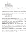
1
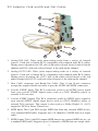
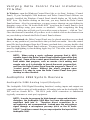
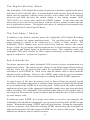
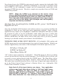
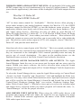
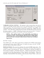
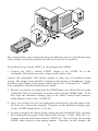
Table of Contents
Introduction . . . . . . . . . . . . . . . . . . . . . . . . . . . . . . . . . . . . . . . . . . . . . . . .2
What’s in the Box? . . . . . . . . . . . . . . . . . . . . . . . . . . . . . . . . . . . . . . . . . . .2
Product Features & Specifications . . . . . . . . . . . . . . . . . . . . . . . . . . . . . . . .3
Minimum System Requirements . . . . . . . . . . . . . . . . . . . . . . . . . . . . . . . . .3
PCI Adapter Card and Break-Out Cable: . . . . . . . . . . . . . . . . . . . . . . . . . . .4
Quick Guide to Getting Started . . . . . . . . . . . . . . . . . . . . . . . . . . . . . . . . . .5
Hardware Installation . . . . . . . . . . . . . . . . . . . . . . . . . . . . . . . . . . . . . . . . .5
Audiophile 2496 Driver & Software Installation . . . . . . . . . . . . . . . . . . . . .6
Windows 98 Installation . . . . . . . . . . . . . . . . . . . . . . . . . . . . . . . . . . . .6
Windows 95 Installation . . . . . . . . . . . . . . . . . . . . . . . . . . . . . . . . . . . .7
Windows NT Installation . . . . . . . . . . . . . . . . . . . . . . . . . . . . . . . . . . .8
Macintosh Installation . . . . . . . . . . . . . . . . . . . . . . . . . . . . . . . . . . . . .8
Verifying Windows Driver Installation . . . . . . . . . . . . . . . . . . . . . . . . . . .10
Verifying Delta Control Panel Installation, PC & Mac . . . . . . . . . . . . . . . .11
Audiophile 2496 System Overview . . . . . . . . . . . . . . . . . . . . . . . . . . . . . .11
Audiophile 2496 Analog Input/Outputs . . . . . . . . . . . . . . . . . . . . . . . .11
The Digital Monitor Mixer . . . . . . . . . . . . . . . . . . . . . . . . . . . . . . . . .12
The Patchbay / Router . . . . . . . . . . . . . . . . . . . . . . . . . . . . . . . . . . . .12
Synchronization . . . . . . . . . . . . . . . . . . . . . . . . . . . . . . . . . . . . . . . . .12
Using the Audiophile 2496 with your Software Application . . . . . . . . . . .13
Audiophile 2496 Control Panel Software . . . . . . . . . . . . . . . . . . . . . . . . . .16
Monitor Mixer Page . . . . . . . . . . . . . . . . . . . . . . . . . . . . . . . . . . . . . .17
Patchbay/Router Page . . . . . . . . . . . . . . . . . . . . . . . . . . . . . . . . . . . . .19
Hardware Settings Page . . . . . . . . . . . . . . . . . . . . . . . . . . . . . . . . . . .21
S/PDIF Page . . . . . . . . . . . . . . . . . . . . . . . . . . . . . . . . . . . . . . . . . . . .24
About Page . . . . . . . . . . . . . . . . . . . . . . . . . . . . . . . . . . . . . . . . . . . .26
Save, Delete, Load Buttons; H/W Installed . . . . . . . . . . . . . . . . . . . . .26
Audiophile 2496 Recording Tutorial . . . . . . . . . . . . . . . . . . . . . . . . . . . . .27
Typical Setup . . . . . . . . . . . . . . . . . . . . . . . . . . . . . . . . . . . . . . . . . . . . . .27
Transferring from DAT to Audiophile 2496 . . . . . . . . . . . . . . . . . . . .28
Transferring from Audiophile 2496 to DAT, monitoring with DAT . . .29
Audiophile 2496 MIDI Setup . . . . . . . . . . . . . . . . . . . . . . . . . . . . . . . . . .30
Troubleshooting Tips for Frequently Asked Questions . . . . . . . . . . . . . . . .31
Appendix A - Technical Specs . . . . . . . . . . . . . . . . . . . . . . . . . . . . . . . . . .33
Limited Lifetime Warranty . . . . . . . . . . . . . . . . . . . . . . . . . . . . . . . . . . . .34
Introduction
Congratulations on your purchase of the Audiophile 2496. The Audiophile 2496 is
a part of the “Delta” series of digital recording systems and interfaces, designed and
manufactured by M Audio, and therefore benefits from the same solid hardware and
software driver technology as the other members of the Delta series.
Even if you are experienced in digital recording, please take the time to read this
manual. It will give you valuable information on installing your new card and the
supporting software, plus help you to fully understand the function and usability of
the Audiophile 2496. Once you’re up and running, you will quickly discover the
power and brilliance, both in sound and design, of your new Audiophile 2496.
What’s in the Box?
Your Audiophile 2496 box contains:
•
•
•
•
This instruction manual.
One Audiophile 2496 PCI adapter card.
One Audiophile 2496 break-out cable for S/PDIF and MIDI connections.
CD or diskette containing software drivers and Delta Control Panel
software for Windows 98/95/NT and Macintosh OS 8.5.1 or higher.
• M Audio Warranty Registration card.
About the Audiophile 2496 Digital Recording Interface
with MIDI
The Audiophile 2496 gives you stereo (or dual mono) analog inputs and outputs,
plus coaxial S/PDIF digital inputs and outputs for a total of 4 ins/ 4 outs of high
quality audio I/O. All audio channels support 24-bit data width and any sampling
rate from 8kHz to 96kHz. The Audiophile is compatible with all major software
programs running on PC and Macintosh computers. The coaxial digital outputs are
Dolby Digital 5.1 surround sound capable, making the Audiophile the perfect “highend” sound card for digital recording, analog or digital transfers, mixing and
mastering, as well as DVD and home theatre applications.
Connect a line-level signal from your instrument, mixer or pre-amp, or use the
record outputs of your stereo receiver into the Audiophile’s analog RCA jacks
located on the PCI card. Record a digital audio signal from your DAT, MiniDisc,
CD, or external A/D converter via the Audiophile’s coaxial S/PDIF input located on
the break-out cable. Control all routing and hardware settings with the Audiophile’s
comprehensive Delta Control Panel software.
2
The Audiophile 2496’s break-out cable also includes MIDI I/O connectors.
Provided are one input and one output for use with external MIDI equipment, such
as sound modules and drum machines. The MIDI I/O may also be used to
synchronize your computer to external devices via MIDI time code.
Within the Audiophile’s PCI chip is a hardware digital mixer. Controlled by the
included Delta Control Panel software, it may handle all of your routing needs, give
you extra control of all left, right and stereo levels, in addition to control of pans,
solos and mutes. The Delta Control Panel also lets you manipulate copy protection
and other status bits in the S/PDIF output signal. In addition it allows you to
configure the Audiophile’s internal clock as a master, or slave it to an incoming
S/PDIF sample rate.
Product Features & Specifications
•
•
•
•
•
•
•
•
•
4x4, 24-bit/96khz, full-duplex recording interface with MIDI I/O.
Configured as a PCI adapter card with external break-out cable.
2x2 analog I/O accepts common unbalanced audio on RCA jacks.
Break-out cable supports coaxial S/PDIF digital I/O and 1x1 (16
channel) MIDI operation.
High analog dynamic range: D/A 104dB, A/D 100.4 dB (both Aweighted).
All data paths support up to 24bit/96kHz performance, no upgrades
necessary.
Comprehensive digital mixing, routing, and monitoring capabilities
with included Delta Control Panel software.
Hardware sample-accurate sync will allow linking of multiple
Audiophile and “Delta” series products.
Windows 95/98 multi-card drivers with ASIO1 and ASIO2 multi-card,
GSIF and EASI drivers included; Windows NT multi-card and Mac OS
drivers with ASIO 1&2 also included.
Minimum System Requirements
• Windows 95, 98, NT, 2000 or ME. Mac OS 8.5.1 or higher.
• Pentium II 266MHz for 96kHz operation. Pentium 200 MMX for 48kHz
or less.
• 128 MB of PC100 RAM for 96kHz operation. 64MB SDRAM for 48kHz
or less.
• Mac G3 or G3 accelerator with 64 MB of RAM, 128 recommended. Some
faster Power PCs will perform adequately.
• UDMA EIDE or fast SCSI HDD recommended.
3
PCI Adapter Card and Break-Out Cable:
1
2
3
7
5
4
6
1. Analog INS 1&2: These jacks input analog audio from a variety of external
sources. Each jack is female RCA, compatible with common male RCA cables.
During stereo operation, the IN1 jack (with white-colored insert) is the left audio
channel and IN2 (with red-colored insert) is the right audio channel.
2. Analog OUTS 1&2: These jacks output analog audio to a variety of external
sources. Each jack is female RCA, compatible with common male RCA cables.
During stereo operation, the OUT1 jack (with white-colored insert) is the left
audio channel and OUT2 (with red-colored insert) is the right audio channel.
3. Host Cable connector and Break-Out Cable: This 15-pin D-sub connector
accepts the supplied break-out cable to provide S/PDIF and MIDI connectors.
4. Coaxial S/PDIF Input: This RCA connector receives an S/PDIF stereo signal
from your coaxial S/PDIF digital source such as a DAT, MiniDisc player or
external A/D converter.
5. Coaxial S/PDIF Output: This RCA connector sends an S/PDIF stereo signal to
your coaxial S/PDIF digital target device such as a DAT, MiniDisc player or
external D/A converter. This output is also used as a Dolby Digital 5.1 (AC3)
output for DVD or Home Theatre use.
6. MIDI Input: This 5-pin DIN accepts MIDI data from any external MIDI device,
via a standard MIDI cable. Supports up to 16-channels of MIDI data on a single
cable.
7. MIDI Output: This 5-pin DIN outputs MIDI data to any external MIDI device, via
a standard MIDI cable. Supports up to 16-channels of MIDI data on a single cable.
4
Quick Guide to Getting Started
Here is what is required to get your Audiophile 2496 up and running:
1. Physically install the Audiophile 2496 card in your computer and connect the
provided break-out cable (see ‘Hardware Installation’).
2. Start Windows and allow Windows’ Plug-and-Play to prompt you for the
Audiophile 2496 drivers via the Add New Hardware wizard. Install drivers and
support software (see ‘Windows Software Installation’).
3. On the Mac, drag the Delta extension to the Extensions folder, and the
appropriate ASIO driver to your application’s ASIO folder. Restart. If not using
ASIO, set the Sound Manager to Delta (see Mac Installation).
4. Configure your digital recording software to use the Audiophile 2496 as its
active audio device (see ‘Using the Audiophile 2496 with your Software
Application’ and also your software application’s manual).
5. Hook up your digital and analog audio gear (see ‘Audiophile 2496 Recording
Tutorials’). Configure your Delta Control Panel software for proper monitoring
and playback.
Hardware Installation
To mechanically install the Audiophile 2496, do the following:
1. Turn off your computer.
2. Remove the computer’s cover and position the computer so that you may easily
access its PCI slots.
3. Select the PCI slot where you will install your Audiophile 2496 PCI host card.
Make sure the slot is a PCI slot. If you don’t know what “PCI slot” means, check
the owner’s manual for your computer. PCI slots are distinguishable from ISA
slots by being shorter and set back farther from the outside of the computer,
however some newer computers have only PCI slots.
4. Before removing the Audiophile 2496 PCI host card from its protective antistatic bag, touch the metal power supply case of the computer in order to
dissipate any static electricity your body may have accumulated. You might
want to pick up a grounding wrist strap (available from electronics stores like
Radio Shack) if you want to be doubly sure you aren’t carrying a static charge
that could damage the card.
5. Remove the metal bracket that covers the access hole on the back of the
computer. This bracket is usually fastened to the computer with a single screw.
5
6. Position the Audiophile 2496 PCI host card over the target PCI slot and fit the
card loosely over it with the card in the upright position. Press the card gently
but firmly downward into the slot until the card is completely and squarely seated
in the slot. If the card seems difficult to seat, a slight rocking motion may help.
7. Fasten the Audiophile 2496 PCI host card’s metal bracket down into the screw
hole on the back of your computer using the screw you removed in step 5 above.
8. Place the cover back on your computer.
Now it is time to connect the Audiophile 2496 break-out cable to the PCI card that
you have just installed. Never attach the break-out cable with the computer turned
on. Doing so could damage the PCI card and/or computer, and void your warranty.
Attach the break-out cable to the PCI host card, and secure with the screws that are
molded into the break-out cable.
Audiophile 2496 Driver & Software Installation
The Audiophile 2496 system includes a “Software Drivers CD” (or diskette) for
Windows 98/95/NT and Macintosh, containing all Windows drivers, Macintosh
drivers (including all ASIO drivers), and Delta Control Panel software. Some
Audiophiles may come with drivers on floppy disk instead. If so, when following the
driver installation procedures outlined below, substitute your computer’s floppy drive
letter for the CD’s drive letter. To install on your system, please follow these steps:
Windows 98 Installation
1. After installing the Audiophile 2496 hardware, boot your system and start
Windows. During the Windows boot procedure, the new hardware will be
automatically detected by the ‘Add New Hardware Wizard’, as shown here.
Click ‘Next>’.
6
2. The ‘Add New Hardware Wizard’ will now ask how to locate the driver.
“Search for the best driver for your device” is already selected. Click ‘Next>’.
3. Windows will give you a selection of locations to search. Make sure that only
“Choose a Path” is checked, or click on the check box to do so. Insert the Drivers
CD into your CD ROM drive. Type in the drive letter of your CD drive (we will
assume here that it is D:\) and the path to the Delta drivers, which will be
D:\DeltaSeries\Delta9X. Click ‘Next>’.
4. The ‘Wizard’ reports that its Windows driver file search has found the M Audio
Audiophile 2496. Click ‘Next>’.
5. Windows is now ready to install the driver files from the specified location.
Click ‘Next>’. Windows will start to copy the files and show you a progress
report screen.
6. The Wizard reports that Windows has finished installing the software. Click
‘Finish’. Your Audiophile 2496 is ready for action.
After completion of the driver installation, Windows may require you to restart
Windows. If it does request a restart, remove the Drivers CD from the CD drive and
respond by clicking “Yes”. The system will restart and your Audiophile 2496 is
ready for play.
Windows 95 Installation
1. After installation of the Audiophile 2496 hardware, boot your system and start
Windows. During the Windows boot procedure, new hardware will be
automatically detected.
2. Choose the Install of “driver from disk provided by hardware manufacturer,”
then click OK.
3. An ‘Install From Disk’ dialog will prompt you to copy files from the A:\ drive.
Insert the Driver software CD into your CD ROM drive. Type in the drive letter
of your CD drive (we will assume here that it is D:\) and the path to the Delta
drivers, which will be D:\DeltaSeries\Delta9X. Click ‘Next>’.
4. Windows will start to copy files, with a progress indicator on the screen. Once
this process completes itself, your Audiophile 2496 will be ready for action.
After completion of the driver installation, Windows may require you to restart
Windows. If it does request a restart, remove the Drivers CD from the CD drive and
respond by clicking “Yes”. The system will restart and your Audiophile 2496 is
ready for play.
7
Windows NT Installation
1. Power up your computer after physically installing the Audiophile 2496 card.
2. Go to Start | Settings | Control Panel and double click on ‘Multimedia.’ Click the
‘Devices’ tab, then click the ‘Add’ button.
3. “Unlisted or Updated Driver” will be highlighted at the top of the list. Click OK.
4. The ‘Install Driver’ box will prompt you to insert the driver disk, and the A:
prompt will appear as the path. Insert the Drivers CD into your CD ROM drive.
Type in the drive letter of your CD drive (we will assume here that it is D:\) and
the path to the Delta drivers, which will be D:\DeltaSeries\Delta_NT. Click OK.
5. The “M Audio Delta Interface Card” driver will appear in the Add Unlisted or
Updated Driver dialog box. Click OK.
6. Windows NT will require you to restart your computer for the changes to take effect.
Choose “Restart Now.” Upon restart, your Audiophile 2496 will be ready for use.
Macintosh Installation
1. Open the System folder on your Macintosh hard drive. In the System folder,
locate the Extensions folder.
2. On you Drivers CD disk, open the Delta Products folder, then the Audiophile
2496 folder. Place the extension file “Audiophile 2496 Driver” in your
Extensions folder by clicking on it and dragging it to the Extensions folder.
3. If you are using a music program that uses ASIO drivers, it will also have an
ASIO folder within the application’s folder. In your Mac Delta Drivers folder
you will find three Audiophile 2496 ASIO drivers. For Cubase versions 4.x, use
the “ASIO2 Delta Audiophile” driver. For Metro, or earlier versions of Cubase,
use the “ASIO Delta Audiophile v3” driver. For any music program that is not
ASIO2 capable, use the “ASIO Delta Audiophile” driver instead (check your
program’s documentation). Place the file “ASIO Delta Audiophile” in your
program’s ASIO folder by clicking on it and dragging it to the ASIO folder.
4. Drag the “DeltaPanel PPC” file onto your Macintosh hard drive. You can run the
Delta Control Panel from any place that’s convenient, though music software
applications that use ASIO will allow you to launch the Delta panel from within
the program. If not, we suggest creating an alias to the control panel by
highlighting it and pressing Command (Apple key)+M. Then, drag the alias to
the desktop.
5. With the Audiophile 2496 PCI card installed, restarting the computer will load
the Audiophile 2496 extension. You will be able to visually see the Delta
extension icon pass by as your system loads extensions.
8
6. Go to the Apple menu |Control Panel | Sound. You should see the “built-in”
sound icon, plus the Delta icon if your Audiophile 2496 is properly installed. If
your music program does use ASIO, leave the Sound Manager driver set to
“built-in” for both Sound In and Sound Out. If your program does not use ASIO
(check your software’s documentation) and you will be using the Sound Manager
to communicate with your Audiophile 2496, set Sound In and Sound Out to
“Delta.” See the section “Hardware Settings Page” in the Audiophile 2496
“Control Panel Software” section for information on selecting Sound Manger
inputs and outputs. Your Audiophile 2496 is now ready for use.
To configure the Audiophile 2496 for MIDI, you will need to have Opcode’s OMS
(Open Music System) installed first. OMS is provided on the CD that came with the
unit, or it can be downloaded from the Midiman website’s MIDISPORT drivers
page. Opening the OMS 2.3.7 folder and double-clicking on the “Install OMS 2.3.7”
program will install OMS in your system. To install the Delta MIDI driver once
OMS is properly installed:
1. Open the “Delta Products” folder on the driver CD, then the Delta Audiophile Mac
folder. Locate the “Delta Audiophile OMS Driver.”
2. On your Macintosh hard drive, in your System folder, you will find an “OMS
Folder.” Drag the Delta Audiophile OMS Driver into the OMS Folder.
3. Restart your computer.
To Configure your Audiophile 2496 MIDI in OMS, go to the Control Panel or Chooser
under the Apple Menu, and make sure AppleTalk is turned off (this is recommended,
although OMS will sense that it is on and prompt you to turn it off). If you are
configuring OMS for the first time, follow these instructions to configure OMS.
1. In the Opcode folder, which you will find on your hard drive, locate the OMS
Applications folder, “then OMS Setup.” Double click on OMS Setup.
2. OMS will inform you that it has not yet been configured. Click OK.
3. The Create A New Studio Setup dialog box now appears. Click OK.
4. The “OMS Driver Search” box asks you to choose the port on which you’ve
attached the Delta MIDI (either Modem or Printer). DO NOT choose a port, just
click “Search.” OMS begins Searching.
5. “OMS Driver Setup” shows the “Delta” MIDI in a list when OMS successfully
finds the driver. Click OK. OMS will now define (shows “Identifying”) the
Delta output port. The “OMS MIDI Device Setup” dialog box will appear
showing the Delta’s output port with a check box to the left of the port, indicating
that the port is enabled. Now click on OK.
6. Next, the “My Studio Setup” appears with a ‘file save’ dialog box over it. You
will now need to save your new Studio Setup before you can assign an
instrument to the Delta’s MIDI output and input. Assign your instrument and
you are done. You may now exit OMS Setup by quitting the application.
9
Verifying Windows Driver Installation
Windows displays the Audiophile 2496 driver status in the Device Manager page of
the System Properties dialog box. The Device Manager page is opened via the
Windows Start button: select Start | Settings | Control Panel | System | Device
Manager. With the Device Manager displayed, click on the ‘+’ next to “Sound,
video and game controllers” to open a list of devices, the Audiophile 2496 being a
device of that nature. Below is an example view of the Device Manager.
This example shows the M Audio Audiophile 2496 and Midiman Midisport 8x8/S
(another product shown here only as an example) entries in the Windows Device
Manager device list. The Audiophile 2496 is properly installed with no conflicts, as
is the Midisport 8x8/S. If you do not see your M Audio Audiophile 2496 in your
Device Manager in this fashion, please jump ahead to the “Troubleshooting” section
of this manual.
10
Verifying Delta Control Panel Installation,
PC & Mac
In Windows, open the Windows Control Panel (do so via Start | Settings | Control
Panel). If your Audiophile 2496 hardware and Delta Control Panel software are
properly installed, the Windows Control Panel should display an “M Audio Delta
H/W” icon. By double-clicking on that icon, you may launch the Delta Control
Panel software. Also for convenience, you may create a shortcut on your desktop by
dragging a copy of the “M Audio Delta H/W” icon from the Control Panel to your
Windows desktop using your mouse or trackball. After completing the drag
operation, a dialog box will ask you if you wish to create a shortcut — click on ‘Yes’.
Once the shortcut is installed, all you have to do is double-click on the shortcut icon
on your desktop to launch the Delta Control Panel software.
On the Macintosh, the Delta Control Panel may be placed anywhere on your hard
drive, or any partition of your hard drive that you find convenient. Once the control
panel file has been dragged from the CD onto your hard drive, you may double click
it to launch the Delta Control Panel software. You may create an alias to the control
panel by highlighting it, then holding Apple key+M. This alias can then be placed
on your desktop.
NOTE: When using a music software program that is ASIO
capable, launch the Delta Control Panel software from within that
program. Some of the control panel functions will be controlled
from within that program, such as master clock setting and
sample rate, so it is desirable to launch the music program first,
and then the Delta Control Panel from the program’s “launch” or
“control panel” button. Without the music program open
however, it is okay to open the Delta Control Panel from your
desktop or other location.
Audiophile 2496 System Overview
Audiophile 2496 Analog Input/Outputs
The Audiophile 2496 Digital Recording Interface’s analog inputs and outputs are
compatible with a variety of audio products. All analog jacks on the Audiophile 2496
PCI card are female RCA. The RCA jacks allow connection to unbalanced
(typically consumer or semi-pro) equipment.
NOTE: In order to preserve its high dynamic range and minimize
distortion, the Audiophile 2496 does not have microphone preamplifiers built into it. Therefore direct connection to a
microphone is not recommended. Instead pass the microphone
signal through a microphone pre-amp (such as the M Audio
DMP2™) and then connect the pre-amp output to the input of the
Audiophile 2496.
11
The Digital Monitor Mixer
The Audiophile 2496 Digital Recording System has a hardware digital audio mixer
built into its PCI controller chip. It accepts digital audio streams from all hardware
inputs and all outgoing software audio devices, mixes them with 36-bit internal
precision and then provides the mixed output to the analog outputs (H/W
OUT1/OUT2 as a stereo pair) and/or the S/PDIF outputs. At the same time the
mixer may be used for stereo mix-down, with the mixer’s output recorded into the
user’s application software. The digital audio mixer is configured and controlled by
the included Delta Control Panel Software.
The Patchbay / Router
In addition to the built-in monitor mixer, the Audiophile 2496 Digital Recording
Interface includes an output patchbay/router. The patchbay/router allows each
output (analog or digital) to be connected to a variety of input sources. The
Audiophile 2496’s outputs may accept audio from software sources (the output
devices visible in your audio software applications) or from hardware sources such
as the analog and digital inputs or the monitor mixer. This capability makes the
Audiophile 2496 quite flexible for WAV output, monitoring, or directly connecting
inputs to outputs for “system test” purposes.
Synchronization
For proper operation, the entire Audiophile 2496 system is always synchronized to a
single master clock. The master clock is chosen via the Delta Control Panel software
and this clock may be derived from either the Audiophile 2496’s internal crystal
oscillators or from S/PDIF In. Most of the time the master clock is taken from the
internal crystal oscillators. However, the S/PDIF option must be used in situations
where the Audiophile 2496 is monitoring or recording from the S/PDIF input port.
As stated, most of the time the master clock is derived from the internal crystal
oscillators. Operation in this mode is similar to that of a generic sound card and should
be used whenever the S/PDIF In is not being used. In this mode, the audio software
application selects one of the supported Audiophile sample rates and starts playback
and/or recording. The Audiophile 2496 hardware then achieves this sample rate by
activating one of its internal crystal oscillators and dividing the rate of that oscillator
by some integer value.
In situations where S/PDIF In is being used (either to record or just monitor), the
Audiophile 2496 should be configured to get its master clock from the S/PDIF In data
stream. Without this setting, S/PDIF input will not function. Setting the Audiophile
to derive its master clock from the incoming S/PDIF stream keeps the Audiophile in
tight synchronization with that external S/PDIF device, and no drift occurs. Digital
transfers are therefore precise and bit-accurate.
12
For advanced users, the S/PDIF In option may be used to operate the Audiophile 2496
at non-standard sample rates. When the Audiophile is set to derive its master clock
from S/PDIF In, the Audiophile’s sample rate will automatically match that of the
incoming S/PDIF data stream. Therefore, sample rates anywhere between 22kHz and
100kHz are possible.
NOTE: When the S/PDIF In is selected as the master clock
source, the Delta Audiophile 2496 mixer’s frequency response will
be affected by whatever sample rates you inject at the S/PDIF In.
This is because (1) the digital mixer operates at the same sample
rate as the rest of the board, and (2) sample rate and frequency
response are directly correlated.
Using the Audiophile 2496 with your Software
Application
Once the Audiophile 2496 hardware and software drivers are properly installed, the
Audiophile is ready for use with your music application software. Some software
applications may require you to highlight or enable the Audiophile 2496 drivers within
the program in order to use the Audiophile, while others may have a utility that
analyzes or profiles the audio cards in your system and enables the drivers. Your
software should have an audio device driver setup page and if you have problems
locating it you should consult your software’s documentation.
WINDOWS MME AUDIO INPUT DEVICES: All Audiophile 2496 analog and
S/PDIF inputs may be used simultaneously for a total of 4 input channels. Within your
software application(s), the names of the Audiophile 2496 audio input devices are:
PCM In 1/2 Delta-AP
S/PDIF In Delta-AP
Mon.Mixer Delta-AP
“AP” in these names stands for “Audiophile.” The PCM In device allows recording
a stereo stream directly from the analog input pair. The S/PDIF In device allows you
to record a stereo stream directly from the S/PDIF input. The Mon.Mixer device
allows stereo recording from the digital “monitor” mixer built-into the Audiophile.
The audio data recorded from this device is the mix of input and output streams set
up in the Delta Control Panel software’s Monitor Mixer (see ‘Audiophile 2496
Control Panel Software’ section).
Note that all of the input devices are stereo. Your application
software may break these down further to “left” and “right” mono
devices. Therefore you may see them as “Left PCM In 1/2
Delta-AP, Right PCM In 1/2 Delta-AP”, “Left S/PDIF In Delta-AP,
Right S/PDIF In Delta-AP”, or “Left Mon. Mixer Delta-AP, Right
Mon. Mixer Delta-AP,” etc. from within your recording software.
13
WINDOWS MME AUDIO OUTPUT DEVICES: All Audiophile 2496 analog and
S/PDIF outputs may be used simultaneously for a total of 4 output channels. Within
your software application(s), the names of the Audiophile 2496 audio output devices
are:
WavOut 1/2 Delta-AP
WavOut S/PDIF Delta-AP
“AP” in these names stands for “Audiophile.” WavOut devices allow playing a
stereo audio stream to the analog hardware outputs (for WavOut 1/2), the S/PDIF
hardware output (for WavOut S/PDIF), or into the hardware router or mixer. Your
application software may break each of these stereo devices down further to “left”
and “right” mono devices. Therefore you may see them as “Left WavOut 1/2
Delta-AP, Right WavOut 1/2 Delta-AP”, or “Left WavOut S/PDIF Delta-AP, Right
WavOut S/PDIF Delta-AP”, from within your music software. Most software will
handle the outputs as stereo pairs but allow you to pan audio left or right within the
pair. Therefore to send a mono output to OUT1 (for example), choose “WavOut 1/2
Delta-AP” and pan that track hard left.
Note that each device name begins with “WavOut.” This is to remind you that these
are software devices, and not always connected directly to output hardware. Instead
they are connected to the Audiophile 2496’s internal patchbay/router and may be
sent to one of several destinations. For more on the patchbay/router, see the
Patchbay/Router section of the Delta Control Panel software discussion.
MACINTOSH SOUND MANAGER INPUTS AND OUTPUTS: The Apple
Sound Manager limits the user to one stereo pair for input and one stereo pair for
output. Within your music software, the device selection when using the Sound
Manager drivers for input and output will be “Sound Manager” both for input source
and for output port.
To select the Sound Manager driver, open the Apple Menu and go to Control Panel
| Sound. For both “Sound In” and “Sound Out,” click and highlight the Delta icon,
then exit. You may select which Delta hardware stereo input pair and stereo output
pair will be used for the Sound Manager’s Sound In and Sound Out in the Delta
Control Panel “Hardware Settings Page” (see section, “Hardware Settings Page”
under “Delta Control Panel”). Whichever stereo pair you select, the software input
and output device selection within your music program will remain the same, i.e.,
“Sound Manager” will be the proper selection.
ASIO DRIVER INPUT DEVICES: When using the ASIO audio drivers with
programs that support ASIO-style audio, the input devices are displayed as mono
devices. Within ASIO software applications, the names of the Delta Audiophile
2496 audio input devices are:
14
Delta-AP1
Delta-AP2
Delta-AP S/PDIF L
Delta-AP S/PDIF R
Delta-AP Mon.Mixer L
Delta-AP Mon.Mixer R
Notice the S/PDIF In and Monitor Mixer names include “L” and “R” characters.
“L” indicates the left channel of the stereo stream, while “R” indicates right channel.
ASIO DRIVER OUTPUT DEVICES: The Audiophile 2496’s ASIO output
devices appear in stereo pairs. Because each device is stereo, you may see “left” and
“right” references within your software application. This allows the application to
pan audio left and right under software control. To send a signal to a Delta ASIO
output 1 (for example) as a mono output send, one would choose “Analog 1/2 DeltaAudiophile 2496” for that track’s output port, and then pan that output hard left. The
ASIO outputs are named as follows:
WavOut 1/2 Delta-AP
S/PDIF L/R Delta-AP
WINDOWS MULTIMEDIA SETTINGS: Windows may be set up to use the
Audiophile as its default audio device, allowing system sounds to be played through
the Audiophile. This also enables you to use the Audiophile with the sound applets
included with Windows. To set this up, go to Control Panel | Multimedia. In the
Audio Properties page, set the Playback and Recording devices to the
Audiophile 2496 input and output devices of your choice.
MIDI DRIVERS: The Audiophile 2496 MIDI drivers, once enabled in your
software’s MIDI Setup, will appear as a MIDI source and a MIDI port within that
program’s track configuration windows. The MIDI input driver is named “MIDI In
Delta-AP”, and the MIDI output driver is named “MIDI Out Delta-AP”. Some
software applications allow you to redefine/rename these devices per supplied or
manually entered instrument definitions.
Windows may also use the Audiophile 2496 as its default MIDI device. This allows
the Audiophile 2496 to be used with the MIDI applications included with Windows.
To set this up, go to Control Panel | Multimedia | MIDI. Set the Audiophile MIDI
driver as the default Windows MIDI driver by clicking on the “MIDI Out Delta-AP”
entry in the driver list, then selecting “OK” or “Apply”.
15
Audiophile 2496 Control Panel Software
ON THE PC: Once the Audiophile 2496 is properly installed, an “M Audio Delta
H/W” icon will be displayed in your Windows Control Panel. By double-clicking
on that icon, you will launch the Delta Control Panel software. You may also launch
the Delta Control Panel software from the desktop if you have previously created a
shortcut there (see “Verifying Delta Control Panel Software Installation” section for
instructions on how to do this). Once the Delta Control Panel software has been
opened, you will see the main panel and its several tabs. To display a desired page,
click on its tab. Below are functional descriptions of each page.
ON THE MAC: The Delta Control Panel must be placed on the hard drive by
dragging the application from the Drivers CD. Once this is done, an alias may be
created by highlighting the Delta Control Panel on the hard drive and pressing the
Apple key+M. Then, this alias may be dragged to the desktop. Double clicking
either will launch the control panel. Once the Delta Control Panel software has been
opened, you will see the main panel and its several tabs. To display a desired page,
click on its tab. Below are functional descriptions of each page. Though most of the
descriptions are Windows based, the functions are identical unless otherwise
indicated. Within each section you will find the necessary name changes for using
the Delta Control Panel “ON THE MAC.”
NOTE: When using a music software program that is ASIO
capable, launch the Delta Control Panel software from within that
program. There will be a button in the ASIO or Audio setup page
that will allow you to do so. Some of the control panel functions
will be controlled from within that program, such as master clock
setting and sample rate, so it is desirable to launch the music
program first, and then the Delta Control Panel from the
program’s “launch” or “control panel” button. Without the music
program open however, it is okay to open the Delta Control Panel
from your desktop or other location.
16
Monitor Mixer Page
The Monitor Mixer is the first page that appears when the Delta Control Panel is
opened, and controls the digital mixer built into the Audiophile 2496’s PCI controller
chip. As described in previous sections, the output of this mixer may be assigned to
the OUT1/OUT2 analog outputs and/or the S/PDIF Out digital output. At the same
time, the mixer outputs may be recorded in stereo by software.
The Monitor Mixer Page is essentially a collection of volume level faders, audio
level (or ‘peak’) meters, and solo/mute controls. For each mixer output and input
channel there is one of each: a volume fader, a peak meter, a solo control, and a mute
control.
LEVEL FADERS: Each volume fader may be controlled by dragging its fader
‘handle’ vertically with the mouse, or by clicking on the ‘handle’ to make it active
and then adjusting it with the up/down cursor keys of your computer keyboard.
Because the mixer has no gain, these faders only attenuate (reduce) the signal levels.
The highest setting is 0dB, or ‘Unity Gain.’ The default fader setting is the quietest
setting, –144dB, which essentially mutes the audio. A pair of level faders may be
“ganged” so that both channels may be adjusted together as a stereo pair.
Also, at the top of each fader and meter is a fader level “fine adjustment” control.
Clicking on the small “up” and “down” arrows will adjust the corresponding fader
setting in 0.5dB increments. Next to each fine adjustment control is a numerical
fader readout that is always current and active.
17
PEAK METERS: Each peak meter indicates an audio signal level in “dB relative
to full-scale.” This means that a full-scale signal is referred to as “0 dB” and a signal
that is 12dB ‘quieter’ than full-scale is referred to as “-12dB.” The meters are
vertically color-coded into three sections: green, yellow and red. The green section
represents a safe zone, ranging from approximately -48dB to -12dB. Most audio
signals should appropriately fill this section of the meter. The yellow section ranges
from -12dB to -3dB as the signal approaches a ‘hotter’ level. For best capture
resolution, recording in this area is both safe and advised. The red section of the
meter ranges from -3dB to 0dB. On the input level meters, a 0dB condition indicates
overload and audio clipping may occur. Therefore be careful to adjust the incoming
audio levels so that they do not peak in the red section too long (you might use the
monitoring capability of the Audiophile 2496 to let your ears be the judge). Please
note that the S/PDIF inputs are actually digital data and can not clip or distort the
Audiophile S/PDIF input in any manner – in other words, the “red zone” of the peak
meter is perfectly safe for digital inputs.
On all output level meters, 0dB indicates full-scale output. Unlike the inputs,
hardware clipping is impossible on the outputs because of the 36-bit resolution built
into the mixer hardware. However, please note that it is possible to mix multiple
tracks within your software application and cause clipping to occur in the output
stream before it reaches the Audiophile output hardware or monitor mixer.
MASTER VOLUME: At the left side of the Monitor Mixer page, you will see the
‘Master Volume’ faders and peak meters. These faders have the longest ‘throw’ and
highest meter resolution of any level controls in the mixer page. They control the
overall stereo level of the mixer output. The peak meters indicate the output signal
levels with respect to full-scale and are directly affected by the settings of the master
volume faders.
MIXER INPUTS: The ‘Mixer Inputs’ are inputs to the monitor mixer. These inputs
accept hardware audio streams (directly from the Audiophile’s analog and digital
input ports) and software audio streams (digital audio generated in software to be
output). This combination of streams makes the monitor mixer extremely flexible.
Each mixer input channel has its own level fader and may be panned anywhere in
the left/right stereo field. Each input also has its own peak meter. The peak meters
indicate the incoming “pre-fader” levels of the incoming audio and are therefore not
affected by the fader settings. However, the input faders do affect the levels of the
signals exiting the mixer and you will see the effect of the input faders on the output
“Master Volume” peak meters.
From left to right, the inputs to the mixer are labeled “WavOut 1/2”, “WavOut
S/PDIF”, “H/W In S/PDIF” and “H/W In 1/2”. The first two inputs accept the digital
audio streams being sent from your software application (or Windows) to the driver
devices with those same names. Each name begins with “WavOut” to remind you
that these are software streams and may not necessarily be routed to any physical
outputs (see Patchbay/Router Page). The rightmost two channels are audio streams
18
from the physical Audiophile 2496 hardware inputs, hence the “H/W” at the front of
each name. On the Mac, these inputs are labeled “SM/ASIO”, as these software
streams will be receiving their digital audio either from the Sound Manager or the
ASIO driver, depending on your selection.
PAN: Each mixer input may be individually panned anywhere in the stereo output
mix. A pan control is positioned directly under each input channel peak meter and
has the appearance of a small vertical pointer. To make a coarse adjustment, click
on the pan control with your mouse and drag it to the desired position. For finer
adjustment (in 1% increments), you may click on the pan control to make it active,
and then use the left/right or up/down cursor keys on your computer keyboard.
Either way, while the pan setting is being adjusted, its value will appear numerically
in the Master Volume’s status box (below the Master Volume Stereo Gang control)
as a percentage from left pan to right pan: -100% represents far left, +100%
represents far right, and 0% represents the center.
SOLO: Each mixer input channel has a “Solo” checkbox associated with it.
Clicking on and activating a Solo box will solo the selected channel by essentially
muting all other signals. When more than one channel has Solo selected, all solo
channels will be summed to the solo ‘buss’ (path), which is what one might consider
an ‘in place’ solo as opposed to a PFL, or pre-fader listen (levels and pans still
apply). Deactivating all solo boxes will return all input channels to their previous
mute/unmute states.
MUTE: Every mixer input channel has a “Mute” checkbox associated with it.
Clicking on and activating the Mute box will remove that signal from the stereo
buss. Deactivating the Mute box will add the signal back into the stereo buss.
STEREO GANG: All input channel pairs have a “Stereo Gang” capability.
Clicking on and activating the Stereo Gang checkbox will link (or “gang”) the
left/right faders so that both channels may be adjusted together as a stereo pair.
Patchbay/Router Page
The Patchbay/Router page allows you to connect each of the Audiophile’s hardware
outputs (a pair of analog outputs and a pair of digital output channels) to specific
audio sources within the Audiophile 2496 board. To display this page, click the
“Patchbay/Router” tab of the Delta Control Panel.
ON THE MAC: Please substitute the name “SM/ASIO” where references are made
to “WavOut.” SM/ASIO are the software outputs on the Mac, while WavOut are the
software outputs on the PC. Substitute “Windows multimedia applet” with “Sound
Manager Applet.”
The leftmost vertical column of Patchbay/Router page, “H/W Out 1/2,” connects this
19
hardware analog stereo pair to one of five stereo sources:
1. The default setting, “WavOut 1/2”, connects ports OUT1 and OUT2 to your
music software or Windows multimedia applet. In other words, when music
software plays audio to the device named “WavOut 1/2 Delta-AP” it will be
routed directly to the Audiophile hardware analog output jacks.
2. The second option, “Monitor Mixer,” connects ports OUT1 and OUT2 to the
outputs of the Audiophile 2496 monitor mixer. For more information of the
capabilities of the monitor mixer, please see the section “Monitor Mixer Page.”
3. The third option, “S/PDIF In,” connects ports OUT1 and OUT2 directly to the
hardware S/PDIF input of the Audiophile card. The left channel of the S/PDIF
In is routed to OUT1 and the right channel of the S/PDIF In is routed to OUT2.
4. The fourth option, “S/PDIF In (L/R Rev.),” functions identically to the third
option, except that the left and right channels are swapped. Therefore in this
mode, the left channel of the S/PDIF In is routed to OUT2 and the right channel
of the S/PDIF In is routed to OUT1. Note that this option is solely for
monitoring/mixing purposes — the S/PDIF In will not record in reverse when
this option is checked.
5. Selection five connects the Audiophile hardware analog inputs 1 & 2 directly to
the Audiophile’s hardware analog outputs 1 & 2. For example, if “H/W In 1/2”
were selected, any signal present at the IN1 port will be copied to OUT1, and any
signal present at the IN2 port will be copied to OUT2.
20
The next vertical column of Patchbay/Router page, “H/W Out S/PDIF,” connects the
Audiophile’s hardware S/PDIF output to one of five stereo sources:
1. The default setting, “WavOut S/PDIF,” connects the S/PDIF Out port to your
music software or Windows multimedia applet. In other words, when music
software plays audio to the device named “WavOut S/PDIF Delta-AP” it will be
routed directly to the hardware S/PDIF output port on your Audiophile card.
2. The second option, “Monitor Mixer,” connects the S/PDIF Out port to the output
of the Audiophile 2496 monitor mixer. For more information on the capabilities
of the monitor mixer, please see the section “Monitor Mixer Page.”
3. The third option, “S/PDIF In,” connects the S/PDIF Out port directly to the
S/PDIF In port of the Audiophile card. The left channel of the S/PDIF In is
routed to the left channel of S/PDIF Out and the right channel of the S/PDIF In
is routed to the right channel of S/PDIF Out.
4. The fourth option, “S/PDIF In (L/R Rev.),” functions identically to the third
option, except that the left and right channels are swapped. Therefore in this
mode, the left channel of the S/PDIF In is routed to the right channel of S/PDIF
Out and the right channel of the S/PDIF In is routed to the left channel of S/PDIF
Out. Note that this option is solely for monitoring/mixing purposes — the
S/PDIF In will not record in reverse when this option is checked.
5. Selection five connects the hardware analog inputs 1 & 2 directly to the
Audiophile’s S/PDIF Out port. Any signal present at the IN1 port will be sent to
the left channel of the S/PDIF Out, and any signal present at the IN2 port will be
sent to the right channel of the S/PDIF Out.
At this point, you may begin to realize the versatility of the Monitor Mixer and the
Patchbay/Router, and the relationship between the two. You may want to re-read this
section and make some practice adjustments within the Delta Control Panel software
to become proficient in routing and mixing. If somewhere in the process you
become confused, you may always restore the default settings to use the Audiophile
as a standard 4-in 4-out sound card — just choose the topmost option in each of the
Patchbay/Router columns.
Hardware Settings Page
The Hardware Settings page of the Delta Control Panel gives you control over
miscellaneous features of the Audiophile 2496. To display this page, click the
“Hardware Settings” tab of the Delta Control Panel.
MASTER CLOCK: This section allows you to select the source of the board’s master
clock: Internal Xtal (‘Xtal’ is an abbreviation for ‘crystal’) or S/PDIF In. Master clock
operation is outlined in the Synchronization section of this manual. Internal Xtal is the
default setting. Be sure to select “S/PDIF In” if you will be recording or monitoring an
21
S/PDIF In stream.
NOTE: If “S/PDIF In” is selected as the master clock source, be
sure to supply a valid S/PDIF signal to the board’s active S/PDIF
input. Otherwise, erratic timing and/or improper sample rates
will be experienced.
Once a master clock source has been selected, its synchronization status is
continually monitored and displayed below the master clock radio buttons. If
internal crystal is selected, the status display will always say “Locked.” On the other
hand, if S/PDIF In is selected as the master clock source, the control panel will
display “Locked” only when a valid S/PDIF signal is detected. It will display
“Unlocked” when there is no signal at the S/PDIF input, or when the signal is corrupt
or invalid for any reason.
CODEC SAMPLE RATE: This section indicates the Audiophile’s current sample
rate. The digital mixer, converters and digital ports are all locked to this sample rate.
If the Audiophile is currently in use by some software application, then this indicated
sample rate was set by the software application. Otherwise, this is the “idle” sample
rate that the Audiophile is using when not in use by software applications. The idle
sample rate is controlled by the “Reset Rate When Idle” checkbox on the Delta
Panel. When “Reset Rate When Idle” is not checked, the Audiophile simply retains
the last sample rate set by an application when the application discontinues use of
the Audiophile. When it is checked, the Audiophile will switch (if necessary) to the
selected sample rate whenever the Audiophile is not in use by an application.
NOTE: Because the digital monitor mixer runs at the sample rate
of the rest of the board, and because sample rate directly affects
frequency response, it may sometimes be desirable to keep the
sample rate at or above 44.1 kHz while using the monitor mixer.
This is accomplished by enabling “Reset Rate When Idle” and
selecting a sample rate of 44.1 kHz or greater.
The Delta Panel also allows you to lock the Audiophile sample rate to some specific
value, and only that value. This is accomplished by checking the “Rate Locked”
checkbox. When you lock the Audiophile sample rate, this will disallow any
application from setting the sample rate differently. If an application attempts to do
so, you will most likely see an error message. The default setting is to leave “Rate
Locked” unchecked.
S/PDIF SAMPLE RATE: When using S/PDIF In as your master clock, this section
tells the driver what the expected S/PDIF input sample rate is. The section is only
displayed when the board is set to use S/PDIF In as the master clock source. From
the list, select the sample rate closest to that of the S/PDIF input data. The sample
rate selected here will be the only sample rate available to the software applications.
Therefore, you must set your audio software application to this same sample rate or
else the application will display an error message.
22
NOTE: When S/PDIF In is the master clock source, the digital
monitor mixer will run at the sample rate received at the S/PDIF
In. Since frequency response and sample rate are directly
related, the mixer frequency response will be directly related to
the sample rate of the S/PDIF input data.
MULTITRACK DRIVER DEVICES: The Audiophile 2496 drivers may
intelligently synchronize the beginning of recording and playback across all audio
devices on the board. When using application software that is capable of using
multiple channels simultaneously, select “Single and In-Sync” to ensure that all audio
channels will begin playback and/or recording at the same time. Otherwise select
“Independent” to allow the audio channels to play independently — this setting may
be desirable if more than one application needs to access the Audiophile 2496
simultaneously. A third option appears when more than one Delta series card is
installed in the machine. The “Multiple Card Sync” selection may be made when you
want all channels across all installed Delta cards to begin playback and/or recording at
the same time.
DMA BUFFER SIZES: This section specifies the amount of system memory
dedicated to digital audio buffering. Setting a buffer size that is too small may result
in clicks or pops in the audio stream as some data may be lost. Larger buffers cause
slightly more latency but prevent the pops and clicks that might occur with smaller
buffer sizes — the default settings are recommended but you may desire to tweak these
default settings to suit your tastes.
ON THE MAC: The Hardware Settings Page in the Macintosh version of the Delta
Control Panel also contains software switches that allow you to select which Delta
input and output stereo pair will be used by the Sound Manager, if and when you
choose the Delta as the Sound Manager input and output device. If you go to the Apple
menu | Control Panel | Sound and highlight the Delta icon for Sound In and Sound Out,
then your Apple system sounds will be routed to the Audiophile hardware output that
you have selected here, and Alert Sounds, if you choose to record, will receive their
input from the Audiophile hardware input that you select here.
You will want to choose the Audiophile for input and output in the Sound control panel
if your music program does not use ASIO and the Delta ASIO drivers. If you are using
the ASIO drivers (see Mac Software Installation), then leave the Sound control panel
selection to “built-in.” With the Sound control panel set to built-in, these Sound
Manager settings in the Delta Control Panel will have no effect.
The Sound Manager driver limits you to using only one of the Audiophile 2496 stereo
input pairs for audio input and only one of the stereo output pairs for output. These do
not need to be matched pairs- you can use inputs 1&2 for Sound In and S/PDIF for
Sound Out, for example, or any combination that you choose. The following screen
shot shows the Hardware Settings page on the Mac with the Sound Manager I/O set to
“Analog 1&2” for Input and “Analog 1&2” for Output. Once you have made a
23
selection, go to the File menu and “Save as Preferences.”
VARIABLE SIGNAL LEVELS: The options in this section allow the user to
match the Audiophile analog output levels to the operating signal levels of external
audio equipment. Two level selections are available: ‘Consumer’ and -10dBV. The
‘Consumer’ setting is the least sensitive of the two settings, and ‘-10dBV’ the most
sensitive. The ‘Consumer’ setting therefore has the most headroom and can accept
the hottest signals. ‘-10dBV’ should be chosen if you feel (or hear) ‘Consumer’
levels clipping or distorting your externally connected equipment.
NOTE: The analog inputs of the Audiophile are fixed to
‘Consumer’ levels. If you want to maintain equal analog signal
levels in and out of the Audiophile (also known as “unity gain”),
you should select consumer output levels to match the consumer
input levels.
S/PDIF Page
The S/PDIF page of the Delta Control Panel configures the S/PDIF output format
and displays the status of the S/PDIF input. To display this page, click the “S/PDIF”
tab of the Delta Control Panel software.
DIGITAL INPUT: This group box displays the current S/PDIF input status. The
Audiophile’s S/PDIF receiver is capable of recognizing a valid input signal versus an
invalid, corrupt or non-present one. When a valid signal is detected at S/PDIF In,
this group box displays “Valid Input Detected.” When an invalid signal is detected
or no signal is present, the group box displays “Invalid or Not Present.” Below this
message are two ‘grayed-out’ buttons: “Coax (RCA)” and “Optical.” These are
functions of the Delta DiO 2496, another product in the M Audio “Delta” series, one
24
with both optical and coaxial S/PDIF inputs. These controls do not apply to the
Audiophile 2496.
DIGITAL OUTPUT FORMAT: Within the “Digital Output Format” group, you
choose the digital audio format of the S/PDIF output.
The default setting,
“Consumer,” is a true S/PDIF format and is recognized by all consumer devices.
The alternate “Professional” setting is an AES/EBU type data stream, but electrically
is S/PDIF. This can be used as an AES/EBU work-around that is recognized by
some but not all AES/EBU devices.
For both consumer and professional output formats, the “Advanced” checkbox will
allow you to force a few particular status bits in the outgoing S/PDIF signal. The
advanced option is for expert users only; however, if you find yourself in
configuration trouble, you can always select the “Restore Defaults” button to restore
the outgoing status bits to their factory settings. When “Consumer” and “Advanced”
are both selected, the group “Consumer Format Advanced Settings” will appear.
When “Professional” and “Advanced” are both selected, the group “Professional
Format Advanced Settings” will appear. These groups are described below:
Consumer Format Advanced Settings (Copy Mode): Copy protection, also known as
Serial Copy Management System (SCMS), is written into the S/PDIF status block, a
reserved part of the S/PDIF digital stream that is independent of the actual audio data
being transmitted. It can be used to inhibit the amount of copies that can be made, or
allow for unlimited copying. Three SCMS modes are available. “Original (Copy
Permitted)” indicates that the source material may be copied by a receiving device.
“1st Generation” indicates that the source material is a first generation or later copy.
Most devices that are capable of recording will reject material with this SCMS mode
set. The final option is “No SCMS” which may be used to override the other two
modes and allow a recording device to successfully record the audio data. Different
manufacturers’ products may interpret these codes differently and require you to set
these bits by “trial-and-error” until proper operation is achieved.
Consumer Format Advanced Settings (Emphasis): This status bit is used to indicate if
pre-emphasis has been applied to the outgoing digital audio signal. The default is
“None” and rarely will any user want to set the value to “50/15uSec” unless the
transmitted audio has been encoded with 50/15uSec pre-emphasis.
Consumer Format Advanced Settings (Data Type): The user may assign the outgoing
data as audio or non-audio data. The default is “Audio.” When sending AC-3 (“Dolby
Digital” 5.1 surround sound) via the Audiophile S/PDIF OUT port to an external
decoder, you should set the Data Type to “Non-Audio.” Most AC-3 surround sound
decoders expect this setting and will reject the information if the Data Type is set to
“Audio.”
Professional Format Advanced Settings (Data Type): The user may assign the outgoing
data as audio or non-audio data. The default is “Audio.” It is possible to send AC-3
type signals out in the professional mode, although it is not usually done this way. If
25
you for some reason must send AC-3 in professional mode, be sure to set the Data Type
to “Non-Audio” for the same reasons outlined in the above paragraph.
Professional Format Advanced Settings (Emphasis): The user may choose to
indicate or not indicate if pre-emphasis has been applied to the outgoing digital
audio signal. The default is “None” and rarely will any user want to set the value to
“CCITT” or “50/15uSec” unless the transmitted audio has been encoded with one of
those types of pre-emphasis.
About Page
The “About” page, while displaying the handsome M Audio logo and applicable
copyright information, also reports the driver version and control panel software
version. If you have Internet browsing capabilities and are currently connected to
the Internet, clicking on the Midiman copyright will link you to the M Audio /
Midiman web site (PC only).
Save, Delete, Load Buttons; H/W Installed
ON THE PC, at the rightmost side of the Delta Control Panel are the Save, Load and
Delete buttons as well as an “installed hardware” set of radio buttons. These controls
appear regardless of what Delta Control Panel page is being displayed.
SAVE, DELETE, LOAD: The Delta Control Panel always retains the last settings
entered. However the Save, Delete, and Load functions expand this capability to store
different sets of control panel settings using different configuration names. These
configurations are then available for recall at a later date and time.
Clicking the ‘Save’ button brings up a dialog box prompting you to name the current
configuration. Once you have done this, click ‘OK’, and your current configuration has
been saved to disk. If you decide that you no longer need a particular configuration, click
the ‘Delete’ button. Highlight the name of the configuration file that you wish to delete,
and click the ‘OK’ button. To recall or reload a saved configuration, click the ‘Load’
button. Highlight the name of the configuration that you wish to recall, and click ‘OK’.
Those settings will now appear in the Delta Control Panel and the driver will
automatically update the hardware.
H/W INSTALLED: Up to four Delta series cards may be installed in a PC system
simultaneously (Note: On the Drivers CD, see the “Multi-card Installation” readme file).
This section displays all installed Delta cards including the Audiophile, and allows you to
select which particular card is under the control of the control panel software. To select a
card for configuration, click the radio button to the left of that particular card in the “H/W
Installed” list. Because of a space restriction, the Audiophile appears abbreviated as “AP”
in this list.
ON THE MAC: To save your Delta Control Panel settings, go to the File menu and select
26
“Save,”or “Save as.” A dialog box will appear, prompting you to name the current
configuration. Once you have done so, click the Save button. To save the current settings
as your default, go to the File menu and choose “Save as Preferences.”
In the upper right-hand corner of the control panel is a “H/W Installed” drop-down
list. At the time of this writing, the Delta Mac ASIO drivers will support only a single
Delta device, and of course the Sound Manager will support only one stereo pair
regardless of how many audio cards are installed in your system. The H/W Installed
list will display “Audiophile 2496 is the active device in the control panel.”
Audiophile 2496 Recording Tutorial
In this section we will explore a sample setup for recording and playback using the
Audiophile 2496 Digital Recording Interface. This is by no means an exhaustive
tutorial but its intent is to help you understand most of the Audiophile’s feature set.
Before beginning, you should open your music software and profile the
Audiophile 2496, enable its drivers, or otherwise setup the software for operation
with the Audiophile 2496.
NOTE: All of these examples refer to the Windows MME driver
names. If you’re using ASIO or Apple Sound Manager drivers,
you’ll need to substitute the appropriate driver names when
referring to software inputs or outputs. On the Macintosh,
substitute “SM/ASIO” for Delta Control Panel references to
“WavOut.”
Typical Setup
Let’s look at a setup that involves a typical transfer of information from DAT to
computer and back to DAT. Here, we’ll be using the Audiophile’s S/PDIF I/O along
with the analog output stereo pair.
NOTE: Because improper connections can potentially make very
loud noises, it’s a good idea to have monitor levels down while
hooking up audio equipment — you may even choose to turn your
computer off before making the connections.
In this example, we will connect a DAT to the Audiophile 2496 break-out cable’s
S/PDIF connectors using coaxial S/PDIF cables (75-ohm impedance RCA-to-RCA).
We’ll also connect the Audiophile’s analog outputs to a sound system for monitoring
purposes. A setup like this might be used to transfer a number of mixes from a DAT
into an audio editing program, performing the appropriate edits, and then
transferring the edited material back to DAT.
27
The example below may at first look long and laborious, but you will find that most
of the settings are factory defaults and will rarely need to be modified.
Transferring from DAT to Audiophile 2496
1. Connect the DAT’s coaxial S/PDIF output to the S/PDIF In of the
Audiophile 2496 break-out cable, using a good quality cable.
Connect the Audiophile 2496 analog outputs to some type of amplified sound
system. The sound system should be equipped with speakers or headphones. From
the Delta Control Panel, set the proper output signal levels “Consumer” or “-10dBV”
to be compatible with that sound system’s inputs.
3. Because you will be recording from the S/PDIF input, you will need to set up the
Audiophile 2496 to synchronize its master clock with the S/PDIF input. To do
this, open the Hardware Settings page of the Delta Control Panel software.
Under Master Clock, select “S/PDIF In.”
4. Next, you will need to tell your application software the expected sample rate.
We’ll use 44.1 kHz in this example. Therefore, on the Hardware Settings page,
set the “S/PDIF Sample Rate” to 44,100.
5. In order to monitor the digital signal coming into the Audiophile 2496, switch to
the Patchbay/Router page of the Delta Panel software. In the “H/W Out 1/2”
column, select the radio button labeled “S/PDIF In.” This will copy all incoming
S/PDIF audio directly to the analog outputs. Therefore, in this example, the
28
monitor mixer will be completely bypassed. Once this assignment is made, you
may play the DAT material at any time and verify that it is making it into the
Audiophile 2496 successfully, by listening to the sound system. This can be
done regardless of whether or not your recording software is open.
Within your recording software, select “S/PDIF In Delta-AP,” as the audio input
device. The Delta input appears as a stereo pair.
7. Start your software recording and then start your DAT material playing. You
should be able to hear the DAT material through your sound system.
Transferring from Audiophile 2496 to DAT, monitoring
with DAT
1. Connect the Audiophile’s S/PDIF Out to the DAT’s coaxial S/PDIF Input using
a good quality cable.
2. Connect the DAT analog outputs to some type of amplified sound system. The
sound system should be equipped with speakers or headphones.
3. Because you will be playing back at the recorded sample rate, you will want to
set the Audiophile’s master clock to use the Audiophile’s internal crystal. Do this
by opening the Hardware Settings page of the Delta Control Panel software and
under Master Clock, selecting “Internal Xtal.” Also, under the Codec Sample
Rate section you should uncheck “Rate Locked” if it is previously checked. This
allows for more flexible sample rate playback.
4. In order to verify proper S/PDIF Output routing, open the Patchbay/Router page
of the control panel software. In the “H/W Out S/PDIF” column, select the radio
button named “WavOut S/PDIF.” Now everything that is sent by your software
to the “WavOut S/PDIF” device will be routed to the hardware S/PDIF output,
and consequently to the DAT.
5. Next let’s make sure the S/PDIF output format is correct. Open the S/PDIF page
of the control panel software. Under Digital Output Format, choose
“Consumer.” Uncheck “Advanced” if it is checked previously. Now click on the
“Restore Defaults” button to set the default S/PDIF outgoing status bits. This
will disable copy protection and also set the emphasis to “none,” allowing the
DAT to accept and record the audio properly.
6. Within your recording software, select “WavOut S/PDIF Delta-AP” as the audio
output device.
7. Start your DAT recording and then start your software playing. You should be
able to hear the DAT material through your sound system. This verifies that the
digital audio is making it into the DAT correctly.
29
Au
dio
24 ph
96 ile
Au
d
in L
in R
ou
tL
o
MI
ut
DI
/S R
/PD
IF
io
L
io
t
Ou
R
d
Au
t
t
u
u
o
o
in
in
I
ID
D
A
T
S
/P
D
IF
M
Audiophile 2496 MIDI Setup
The Audiophile’s MIDI input and output ports may be connected to external MIDI
devices. The diagram below shows connection to a MIDI controller keyboard, which
is also being used as a sound module. The MIDI output of the Audiophile 2496 may
be used with just a sound module, while the MIDI input may alternately be used to
receive MIDI timecode for synchronization purposes.
1. Connect the MIDI out port of your controller keyboard to the MIDI In of the
Audiophile breakout cable using a standard MIDI cable.
2. Connect the MIDI Out port of the Audiophile breakout cable to the MIDI in of
your controller keyboard, also using a standard MIDI cable.
3. Connect the audio outputs of the keyboard to either a mixer, sound system, or the
audio inputs of the Audiophile 2496 card.
30
Troubleshooting Tips for Frequently Asked
Questions
Problem: No Sound.
Possible Cause 1: The Audiophile 2496 hardware or software device drivers are
not properly installed. See the installation sections of this manual for further information.
Possible Cause 2: There is a resource conflict between the Audiophile 2496
and another device in your computer. Check the Audiophile 2496 configuration
(Address, IRQ) against those of the other installed devices. If necessary, change the
settings for the one or more of the devices.
Possible Cause 3: Your application software has not been properly
configured to use the Audiophile 2496 as its audio output device.
Possible Cause 4: Misrouted outputs in the Delta Control Panel. Check the
Delta Control Panel’s Patchbay/Router page to verify output routing assignments.
Also, make sure that if the output is routed from the digital mixer, that the mixer’s
faders, solo and mute controls are set up properly.
Possible Cause 5: Improper connections of the audio accessories. Verify
that the Audiophile 2496 analog audio outputs are properly connected to a digital
mix deck or external mixer/amplifier, or the S/PDIF Out is connected to an external
digital audio device capable of receiving S/PDIF.
Problem: No visual activity on Audio Input volume (VU) meters of user
software.
Possible Cause 1:: The Audiophile 2496 input devices are not properly
selected in the user’s application software.
Possible Cause 2:: If the software is recording from the Audiophile’s
monitor mixer device, be sure that the mixer’s faders, solo and mute controls are set
up properly.
Possible Cause 3:: Improper connections to audio accessories.
Problem: Repetitious Sound.
Possible Cause: An IRQ resource conflict. Often this will result in a small
segment of sound (0.5 to 1 second) repeating itself over and over, sometimes
completely locking up the computer. See the general troubleshooting suggestions at
the beginning of this section.
Problem: I’m getting some pops and clicks in my audio recording.
Possible Cause 1:: Input levels are too “hot,” causing clipping or input
distortion. Make sure you have the proper signal levels coming from your source
audio device, and lower the output if necessary. The incoming levels may be easily
viewed from the Delta Control Panel peak meters.
Possible Cause 2:: Your application software may not have the proper audio
buffer sizes set. Each software application handles this differently, but typically
there is somewhere in the software’s setup to set the size of the playback and
recording buffers used by the application. Some applications also require you to run
31
a card calibration (sometimes called “profiling”) the first time you use the software
with a new audio card.
Possible Cause 3: Some accelerated graphics cards use excessive amounts
of system bandwidth, preventing the recording buffer of an audio card from keeping
up with demand. This can cause clicks in the recording. Reducing or turning off the
graphics card’s graphics acceleration feature often resolves this problem. In
Windows, the level of graphics acceleration is accessed from Start | Settings
| Control Panel | System | Performance | Graphics.
Problem: The sound from the monitor mixer is muffled. It sounds as if it were
running through a mixer with the treble control turned all the way down!
Possible Cause: The current Audiophile 2496 sample rate is too low. The
monitor mixer is a digital device that runs at the current sample rate of the
Audiophile 2496 board. The frequency response of the mixer is roughly one-half of
the sample rate. There is no way to prevent this lost frequency response while
playing back or recording at a low sample rate. However, it may be prevented when
the system is idle. See the “CODEC SAMPLE RATE” paragraph of the section
‘Hardware Settings Page’ for more information.
Problem: My software application keeps telling me “sample rate not supported”
or some similar message.
Possible Cause: You have “Rate Locked” set in the Delta Control Panel.
This makes only the sample rate specified in the panel available to Windows and
software applications. Either uncheck “Rate Locked” or set your application to that
locked sample rate.
Problem: Clicking sounds occur at the beginning of and immediately after each
sound.
Possible Cause: Sample rate changes often cause clicks and pops to occur in
the audio. These sample rate changes can happen at the start and end of audio
playback. If “Reset Rate When Idle” is checked under the Hardware page of the
Delta Control Panel software, the Audiophile is changing its sample rate back to a
specified rate each time a sound ends. Then if a sound starts again at a different
sample rate, the Audiophile clock is changed again to meet that new sample rate. To
eliminate this, uncheck the “Reset Rate When Idle” checkbox.
Problem: I am playing AC-3 or surround sound data from a software application
on my computer, sending the data from Audiophile S/PDIF Out to my home theatre’s
AC-3 decoder. However, the decoder does not recognize the signal and therefore
refuses to put out any audio.
Possible Cause: There is a bit within the S/PDIF digital audio stream that
defines the S/PDIF content as audio or non-audio. Most AC-3 surround sound
decoders expect this setting to be non-audio and will otherwise reject the
information. Go to the S/PDIF page of the Delta Control Panel, select Consumer and
Advanced Settings, and then select “Non-Audio” as the data type.
32
Appendix A - Technical Specs
Analog Audio
Peak Analog Input Signal:
Peak Analog Output Signal:
Max Converter Data Width:
Dynamic Range:
Outputs:
Inputs:
THD (at 0dBFS):
Frequency Response:
Input Impedance:
Connectors:
Digital Audio
Maximum Word Width:
Digital Input Format:
Digital Input Sample Rate:
Digital Output Format:
+2dBV.
+2dBV (Consumer setting),
-4dBV (-10dBV setting).
24 bits.
104dB (a-weighted).
100.4dB (a-weighted).
less than 0.002%,
22Hz - 22kHz, -0.4,-0.4dB.
10k ohms minimum.
Gold-plated RCA female, on PCI card.
Digital Output Sample Rate:
Connectors:
24 bits.
S/PDIF coaxial, 0.5V to 5V peak-to-peak.
8kHz to 96kHz.
S/PDIF coaxial, 0.5V peak-to-peak;
AES/EBU data stream over S/PDIF coaxial.
8kHz to 96kHz.
Gold-plated RCA, female, on break-out cable.
MIDI
I/O Configuration:
Connectors:
1-in, 1-out; 16 MIDI channels in and out.
Standard MIDI 5-pin DIN on break-out cable.
Adapter Resource Requirements (PC only)
IRQ:
One required
I/O Addresses:
Four blocks: 32, 16, 16, and 64 bytes
DMA Channels:
None required
33
Limited Lifetime Warranty
MIDIMAN warrants that this product is free of defects in materials and
workmanship under normal use so long as the product is: owned by the original
purchaser; the original purchaser has proof of purchase from an authorized
MIDIMAN dealer; and the purchaser has registered his/her ownership of the
product by sending in the completed warranty card.
This warranty explicitly excludes power supplies and included cables which
may become defective as a result of normal wear and tear.
In the event that MIDIMAN receives written notice of defects in materials or
workmanship from such an original purchaser, MIDIMAN will either replace
the product, repair the product, or refund the purchase price at its option. In the
event any repair is required, shipment to and from MIDIMAN and a nominal
handling charge shall be born by the purchaser. In the event that repair is
required, a Return Authorization number must be obtained from MIDIMAN.
After this number is obtained, the unit should be shipped back to MIDIMAN in
a protective package with a description of the problem and the Return
Authorization clearly written on the package.
In the event that MIDIMAN determines that the product requires repair because
of user misuse or regular wear, it will assess a fair repair or replacement fee.
The customer will have the option to pay this fee and have the unit repaired and
returned, or not pay this fee and have the unit returned unrepaired.
The remedy for breach of this limited warranty shall not include any other
damages. MIDIMAN will not be liable for consequential, special, indirect, or
similar damages or claims including loss of profit or any other commercial
damage, even if its agents have been advised of the possibility of such damages,
and in no event will MIDIMAN’s liability for any damages to the purchaser or
any other person exceed the price paid for the product, regardless of any form
of the claim. MIDIMAN specifically disclaims all other warranties, expressed
or implied. Specifically, MIDIMAN makes no warranty that the product is fit
for any particular purpose.
This warranty shall be construed, interpreted, and governed by the laws of the
state of California. If any provision of this warranty is found void, invalid or
unenforceable, it will not affect the validity of the balance of the warranty,
which shall remain valid and enforceable according to its terms. In the event
any remedy hereunder is determined to have failed of its essential purpose, all
limitations of liability and exclusion of damages set forth herein shall remain in
full force and effect.
34