1
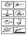
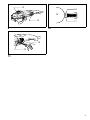
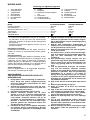
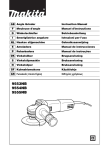
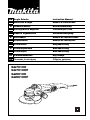
GB Angle Grinder
Instruction Manual
F
Meuleuse d’angle
Manuel d’instructions
D
Winkelschleifer
Betriebsanleitung
I
Smerigliatrice angolare
Istruzioni per l’uso
NL Haakse slijpmachine
Gebruiksaanwijzing
E
Amoladora
Manual de instrucciones
P
Rebarbadora
Manual de instruções
DK Vinkelsliber
Brugsanvisning
S
Vinkelslipmaskin
Bruksanvisning
N
Vinkelsliper
Bruksanvisning
SF Kulmahiomakone
Käyttöohje
GR Γωνιακς Λειαντήρας
Οδηγίες χρήσεως
GA7010C
GA7010CF
GA9010C
GA9010CF
1
2
3
1
2
5
6
4
7
8
3
4
9
7
10
11
5
6
12
A
B
15˚
1
7
2
8
13
16
15
14
9
17
10
18
19
11
3
Symbols
The followings show the symbols used for the tool. Be sure that you understand their meaning before use.
Symboles
Nous donnons ci-dessous les symboles utilisés pour l’outil. Assurez-vous que vous en avez bien compris la signification avant d’utiliser l’outil.
Symbole
Die folgenden Symbole werden für die Maschine verwendet. Machen Sie sich vor der Benutzung unbedingt mit ihrer
Bedeutung vertraut.
Simboli
Per questo utensile vengono usati i simboli seguenti. Bisogna capire il loro significato prima di usare l’utensile.
Symbolen
Voor dit gereedschap worden de volgende symbolen gebruikt. Zorg ervoor dat u de betekenis van deze symbolen
begrijpt alvorens het gereedschap te gebruiken.
Símbolos
A continuación se muestran los símbolos utilizados con esta herramienta. Asegúrese de que entiende su significado
antes de usarla.
Símbolos
O seguinte mostra os símbolos utilizados para a ferramenta. Certifique-se de que compreende o seu significado antes
da utilização.
Symboler
Nedenstående symboler er anvendt i forbindelse med denne maskine. Vær sikker på, at De har forstået symbolernes
betydning, før maskinen anvendes.
Symboler
Det följande visar de symboler som används för den här maskinen. Se noga till att du förstår deras innebörd innan
maskinen används.
Symbolene
Følgende viser de symblene som brukes for maskinen. Det er viktig å forstå betydningen av disse før maskinen tas i
bruk.
Symbolit
Alla on esitetty koneessa käytetyt symbolit. Opettele näiden merkitys, ennen kuin käytät konetta.
Σύµβολα
Τα ακλουθα δείχνουν τα σύµβολα που χρησιµοποιούνται για το µηχάνηµα. Βεβαιωθείτε τι καταλαβαίνετε
τη σηµασία τους πριν απ τη χρήση.
4
❏ Read instruction manual.
❏ Lire le mode d’emploi.
❏ Bitte Betriebsanleitung lesen.
❏ Leggete il manuale di istruzioni.
❏ Lees de gebruiksaanwijzing.
❏ Lea el manual de instrucciones.
❏ Leia o manual de instruções.
❏ Læs brugsanvisningen.
❏ Läs bruksanvisningen.
❏ Les bruksanvisingen.
❏ Katso käyttöohjeita.
❏ ∆ιαβάστε τις οδηγίες χρήσης.
❏ DOUBLE INSULATION
❏ DOUBLE ISOLATION
❏ DOPPELT SCHUTZISOLIERT
❏ DOPPIO ISOLAMENTO
❏ DUBBELE ISOLATIE
❏ DOBLE AISLAMIENTO
❏ DUPLO ISOLAMENTO
❏ DOBBELT ISOLERET
❏ DUBBEL ISOLERING
❏ DOBBEL ISOLERING
❏ KAKSINKERTAINEN ERISTYS
❏ ∆ΙΠΛΗ ΜΟΝΩΣΗ
❏ Wear safety glasses.
❏ Porter des lunettes de protection.
❏ Schutzbrille tragen.
❏ Indossare occhiali di protezione.
❏ Draag een veiligheidsbril.
❏ Póngase gafas de seguridad.
❏ Utilize óculos de segurança.
❏ Bær sikkerhedsbriller.
❏ Bär skyddsglasögon.
❏ Bruk vernebriller.
❏ Käytä suojalaseja.
❏ Φορέστε γυαλιά ασφαλείας.
ENGLISH
Explanation of general view
1
2
3
4
5
6
7
Shaft lock
Switch trigger
Lock lever
Side grip
Wheel guard
Bearing box
Screw
8 Lever
9 Lock nut
10 Depressed center wheel/Multi
disc
11 Inner flange
12 Lock nut wrench
13 Exhaust vent
14
15
16
17
18
19
Inhalation vent
Commutator
Insulating tip
Carbon brush
Screwdriver
Brush holder cap
SPECIFICATIONS
Model
GA7010C/GA7010CF
Depressed center wheel diameter ...............................................180 mm
Spindle thread .............................................................................M14
No load speed (min-1) ..................................................................8,400
Overall length ..............................................................................453 mm
Net weight ....................................................................................3.4 kg
Safety class ..................................................................................
/II
• Due to our continuing program of research and development, the specifications herein are subject to change
without notice.
• Note: Specifications may differ from country to country.
9.
Intended use
The tool is intended for grinding, sanding and cutting of
metal and stone materials without the use of water.
10.
Power supply
The tool should be connected only to a power supply of
the same voltage as indicated on the nameplate, and can
only be operated on single-phase AC supply. They are
double-insulated in accordance with European Standard
and can, therefore, also be used from sockets without
earth wire.
Safety hints
For your own safety, please refer to the enclosed safety
instructions.
ENB031-6
2.
3.
4.
5.
6.
7.
8.
12.
13.
14.
15.
16.
ADDITIONAL SAFETY RULES
1.
11.
Always use eye and ear protection. Other personal protective equipment such as dust mask,
gloves, helmet and apron should be worn.
Always be sure that the tool is switched off and
unplugged before carrying out any work on the
tool.
Keep guards in place.
Use only wheels with correct size and wheels
having a maximum operating speed at least as
high as the highest No Load Speed marked on
the tool’s nameplate. When using depressed
center wheels, be sure to use only fiberglassreinforced wheels.
Check the wheel carefully for cracks or damage
before operation. Replace cracked or damaged
wheel immediately.
Observe the instructions of the manufacturer for
correct mounting and use of wheels. Handle and
store wheels with care.
Do not use separate reducing bushings or adaptors to adapt large hole abrasive wheels.
Use only flanges specified for this tool.
17.
18.
19.
20.
21.
22.
23.
24.
25.
26.
GA9010C/GA9010CF
230 mm
M14
6,000
453 mm
3.4 kg
/II
Do not damage the spindle, the flange (especially the installing surface) or the lock nut. Damage to these parts could result in wheel
breakage.
For tools intended to be fitted with threaded hole
wheel, ensure that the thread in the wheel is long
enough to accept the spindle length.
Before using the tool on an actual workpiece,
test run the tool at the highest no load speed for
at least 30 seconds in a safe position. Stop
immediately if there is any vibration or wobbling
that could indicate poor installation or a poorly
balanced wheel. Check the tool to determine the
cause.
Check that the workpiece is properly supported.
Hold the tool firmly.
Keep hands away from rotating parts.
Make sure the wheel is not contacting the workpiece before the switch is turned on.
Use the specified surface of the wheel to perform the grinding.
Do not use cutting off wheel for side grinding.
Watch out for flying sparks. Hold the tool so that
sparks fly away from you and other persons or
flammable materials.
Pay attention that the wheel continues to rotate
after the tool is switched off.
Do not touch the workpiece immediately after
operation; it may be extremely hot and could
burn your skin.
Position the tool so that the power cord always
stays behind the tool during operation.
If working place is extremely hot and humid, or
badly polluted by conductive dust, use a shortcircuit breaker (30 mA) to assure operator safety.
Do not use the tool on any materials containing
asbestos.
Do not use water or grinding lubricant.
Ensure that ventilation openings are kept clear
when working in dusty conditions. If it should
become necessary to clear dust, first disconnect
the tool from the main supply (use non metallic
objects) and avoid damaging internal parts.
When use cut-off wheel, always work with the
dust collecting wheel guard required by domestic regulation.
5
27. Cutting discs must not be subjected to any lateral pressure.
ASSEMBLY
SAVE THESE INSTRUCTIONS.
CAUTION:
Always be sure that the tool is switched off and
unplugged before carrying out any work on the tool.
FUNCTIONAL DESCRIPTION
Installing side grip (handle) (Fig. 3)
CAUTION:
Always be sure that the tool is switched off and
unplugged before adjusting or checking function on the
tool.
CAUTION:
Always be sure that the side grip is installed securely
before operation.
Shaft lock (Fig. 1)
CAUTION:
Never actuate the shaft lock when the spindle is moving.
The tool may be damaged.
Press the shaft lock to prevent spindle rotation when
installing or removing accessories.
Switch action (Fig. 2)
CAUTION:
Before plugging in the tool, always check to see that the
switch trigger actuates properly and returns to the “OFF”
position when released.
For tool with the lock-on switch
To start the tool, simply pull the switch trigger. Release
the switch trigger to stop. For continuous operation, pull
the switch trigger and then push in the lock lever. To stop
the tool from the locked position, pull the switch trigger
fully, then release it.
For tool with the lock-off switch
To prevent the switch trigger from being accidentally
pulled, a lock lever is provided. To start the tool, push in
the lock lever and then pull the switch trigger. Release
the switch trigger to stop.
For tool with the lock on and lock-off switch
To prevent the switch trigger from being accidentally
pulled, a lock lever is provided. To start the tool, push in
the lock lever and then pull the switch trigger. Release
the switch trigger to stop.
For continuous operation, push in the lock lever, pull the
switch trigger and then push the lock lever further in.
To stop the tool from the locked position, pull the switch
trigger fully, then release it.
Screw the side grip securely on the position of the tool as
shown in the figure.
Installing or removing wheel guard (Fig. 4 & 5)
CAUTION:
The wheel guard must be fitted on the tool so that the
closed side of the guard always points toward the operator.
Loosen the lever on the wheel guard. Mount the wheel
guard with the protrusion on the wheel guard band
aligned with the notch on the bearing box. Then rotate
the wheel guard around to the position shown in the figure. Tighten the lever to fasten the wheel guard. If the
lever is too tight or too loosen to fasten the wheel guard,
loosen or tighten the screw to adjust the tightening of the
wheel guard band.
To remove wheel guard, follow the installation procedure
in reverse.
Installing or removing depressed center grinding
wheel/Multi-disc (accessory)
Mount the inner flange onto the spindle. Fit the wheel/
disc on the inner flange and screw the lock nut onto the
spindle. (Fig. 6)
To tighten the lock nut, press the shaft lock firmly so that
the spindle cannot revolve, then use the lock nut wrench
and securely tighten clockwise.
To remove the wheel, follow the installation procedure in
reverse. (Fig. 7)
Super flange
Models GA7010CF and GA9010CF are standardequipped with a super flange. Only 1/3 of efforts needed
to undo lock nut, compared with conventional type.
Electronic function
OPERATION
The tools equipped with electronic function are easy to
operate because of the following features.
WARNING:
• It should never be necessary to force the tool. The
weight of the tool applies adequate pressure. Forcing
and excessive pressure could cause dangerous wheel
breakage.
• ALWAYS replace wheel if tool is dropped while grinding.
• NEVER bang or hit grinding disc or wheel onto work.
• Avoid bouncing and snagging the wheel, especially
when working corners, sharp edges etc. This can
cause loss of control and kickback.
• NEVER use tool with wood cutting blades and other
sawblades. Such blades when used on a grinder frequently kick and cause loss of control leading to personal injury.
Constant speed control
Possible to get fine finish, because the rotating speed is
kept constant even under loaded condition.
Additionally, when the load on the tool exceeds admissible levels, power to the motor is reduced to protect the
motor from overheating. When the load returns to admissible levels, the tool will operate as normal.
Soft start feature
Soft start because of suppressed starting shock.
6
CAUTION:
• Never switch on the tool when it is in contact with the
workpiece, it may cause an injury to operator.
• Always wear safety goggles or a face shield during
operation.
• After operation, always switch off the tool and wait until
the wheel has come to a complete stop before putting
the tool down.
ALWAYS hold the tool firmly with one hand on rear handle and the other on the side handle. Turn the tool on and
then apply the wheel or disc to the workpiece.
In general, keep the edge of the wheel or disc at an angle
of about 15 degrees to the workpiece surface.
During the break-in period with a new wheel, do not work
the grinder in the B direction or it will cut into the workpiece. Once the edge of the wheel has been rounded off
by use, the wheel may be worked in both A and B direction. (Fig. 8)
MAINTENANCE
CAUTION:
Always be sure that the tool is switched off and
unplugged before attempting to perform inspection or
maintenance.
ACCESSORIES
CAUTION:
These accessories or attachments are recommended for
use with your Makita tool specified in this manual. The
use of any other accessories or attachments might
present a risk of injury to persons. Only use accessory or
attachment for its stated purpose.
If you need any assistance for more details regarding
these accessories, ask your local Makita service center.
•
•
•
•
•
•
•
•
•
•
•
•
•
•
•
Wheel guard (Wheel cover)
Inner flange
Depressed center wheels
Lock nut (For depressed center wheel)
Rubber pad
Abrasive discs
Lock nut (For abrasive disc)
Lock nut wrench
Cut-off wheels
Inner flange (For cut-off wheel)
Outer flange (For cut-off wheel)
Wire cup brush
Side grip
Dust collecting wheel guard
Dust cover attachment
The tool and its air vents have to be kept clean. Regularly
clean the tool’s air vents or whenever the vents start to
become obstructed. (Fig. 9)
Replacing carbon brushes (Fig. 10 & 11)
When the resin insulating tip inside the carbon brush is
exposed to contact the commutator, it will automatically
shut off the motor. When this occurs, both carbon
brushes should be replaced. Keep the carbon brushes
clean and free to slip in the holders. Both carbon brushes
should be replaced at the same time. Use only identical
carbon brushes.
Use a screwdriver to remove the brush holder caps. Take
out the worn carbon brushes, insert the new ones and
secure the brush holder caps.
To maintain product SAFETY and RELIABILITY, repairs,
any other maintenance or adjustment should be performed by Makita Authorized Service Centers, always
using Makita replacement parts.
7
NEDERLANDS
Verklaring van algemene gegevens
1
2
3
4
5
6
7
Asvergrendeling
Trekschakelaar
Veiligheidspal
Zijhandgreep
Beschermkap
Kussenblokkast
Schroef
8 Hendel
9 Borgmoer
10 Verzonken-centerschijf/Multidisc
11 Binnenflens
12 Borgmoersleutel
13 Luchtuitlaatopening
14
15
16
17
18
19
Luchtinlaatopening
Collector
Isolerend uiteinde
Koolborstel
Schroevendraaier
Koolborsteldop
TECHNISCHE GEGEVENS
Model
GA7010C/GA7010CF
Diameter slijpschijf ....................................................................... 180 mm
Asschroefdraad ........................................................................... M14
Toerental onbelast/min. (min-1) .................................................... 8 400
Totale lengte ................................................................................ 453 mm
Netto gewicht ............................................................................... 3,4 kg
Veiligheidsklasse ..........................................................................
/II
• In verband met ononderbroken research en ontwikkeling behouden wij ons het recht voor bovenstaande
technische gegevens te wijzigen zonder voorafgaande
kennisgeving.
• Opmerking: De technische gegevens kunnen van land
tot land verschillen.
Doeleinden van gebruik
Dit gereedschap is bedoeld voor het slijpen, schuren en
snijden van metaal- en steenmaterialen zonder gebruik
van water.
Stroomvoorziening
Dit gereedschap mag alleen worden aangesloten op een
stroombron van hetzelfde voltage als aangegeven op de
naamplaat, en kan alleen op enkel-fase wisselstroom
worden gebruikt. Dit gereedschap is dubbel-geïsoleerd
volgens de Europese standaard en kan derhalve ook op
een niet-geaard stopcontact worden aangesloten.
Veiligheidswenken
Voor uw veiligheid dient u de bijgevoegde Veiligheidsvoorschriften nauwkeurig op te volgen.
6.
7.
8.
9.
10.
11.
AANVULLENDE
VEILIGHEIDSVOORSCHRIFTEN VOOR HET
GEREEDSCHAP
1.
2.
3.
4.
5.
Draag tijdens het werk altijd oog- en oorbescherming. Draag ook andere veiligheidsuitrusting
zoals een stofmasker, handschoenen een helm
en een voorschoot.
Schakel het gereedschap uit en haal zijn netsnoer uit het stopcontact alvorens enig werk aan
het gereedschap uit te voeren.
Houd de beschermkappen op hun plaats.
Gebruik uitsluitend schijven van de juiste
grootte en met een maximaal bedrijfstoerental
dat minstens even hoog is als het hoogste “No
Load Speed” (toerental onbelast) dat op de
naamplaat van het gereedschap is opgegeven.
Wanneer u schijven met een verzonken asgat
gebruikt, gebruik dan uitsluitend schijven die
met glasvezel zijn versterkt.
Controleer de schijf vóór elk gebruik zorgvuldig
op scheuren, barsten of beschadiging. Vervang
een gescheurd, gebarsten of beschadigd schijf
onmiddellijk.
12.
13.
14.
15.
16.
17.
18.
19.
GA9010C/GA9010CF
230 mm
M14
6 000
453 mm
3,4 kg
/II
Volg de instructies van de fabrikant voor het juist
monteren en gebruiken van de schijven zorgvuldig op. Behandel de schijven voorzichtig en berg
deze met zorg op.
Gebruik geen afzonderlijke verloopmoffen of
adapters om schuurschijven met een groot asgat
aan dit gereedschap aan te passen.
Gebruik uitsluitend flenzen die voor dit gereedschap zijn bestemd.
Pas op dat u de as, de flens (vooral het montagevlak) of de klembout niet beschadigt. Beschadiging van deze onderdelen kan leiden tot
schijfbreuk.
Voor gereedschap waarop schijven met een
geschroefd asgat dienen gemonteerd te worden,
moet u ervoor zorgen dat de schroefdraad in de
schijf lang genoeg zodat de as helemaal erin
gaat.
Laat het gereedschap tenminste 30 seconden
lang met het maximale onbelaste toerental
draaien op een veilige plaats alvorens het op een
werkstuk te gebruiken. Stop het gereedschap
onmiddellijk als er sprake is van trilling of
beving die het gevolg kunnen zijn van onjuiste
installatie of een slecht uitgebalanceerde schijf.
Controleer het gereedschap om de oorzaak van
het probleem te bepalen.
Zorg ervoor dat het werkstuk goed ondersteund
is.
Houd het gereedschap stevig vast.
Houd uw handen uit de buurt van draaiende
onderdelen.
Zorg ervoor dat schuurschijf het werkstuk niet
raakt voordat het gereedschap is ingeschakeld.
Voor slijpwerkzaamheden moet u het schijfoppervlak gebruiken dat daarvoor bestemd is.
Gebruik de doorslijpschijf niet voor zijdelings
slijpen.
Pas op voor rondvliegende vonken. Houd het
gereedschap zodanig vast dat er geen vonken
op uzelf, andere personen of ontvlambaar materiaal terecht kunnen komen.
Houd er rekening mee dat de schijf nog een tijdje
blijft draaien nadat het gereedschap is uitgeschakeld.
17
20. Raak het werkstuk niet aan onmiddellijk na het
werk; het werkstuk kan gloeiend heet zijn en
brandwonden veroorzaken.
21. Plaats het gereedschap zodanig dat zijn netsnoer tijdens het gebruik altijd achter het gereedschap blijft.
22. Indien de werkplaats uiterst warm en vochtig is,
of erg verontreinigd is door geleidend stof,
gebruik dan een stroomonderbreker (30 mA) om
de veiligheid van de gebruiker te verzekeren.
23. Gebruik het gereedschap niet op materialen die
asbest bevatten.
24. Gebruik geen water of slijpolie.
25. Zorg dat de ventilatieopeningen niet geblokkeerd zijn wanneer u in stoffige omgevingen
werkt. Indien stof verwijderd moet worden, trek
dan eerst de stekker uit het stopcontact (gebruik
niet-metalen voorwerpen) en let op dat u geen
interne onderdelen van het gereedschap beschadigt.
26. Wanneer u een afkortschijf gebruikt, moet u
altijd de stofvangkap gebruiken die door de
plaatselijke voorschriften wordt vereist.
27. Snijschijven mogen niet aan laterale druk worden blootgesteld.
BEWAAR DEZE VOORSCHRIFTEN.
BESCHRIJVING VAN DE FUNCTIES
LET OP:
Zorg altijd dat het gereedschap is uitgeschakeld en de
stekker uit het stopcontact is verwijderd alvorens functies
op het gereedschap af te stellen of te controleren.
Asvergrendeling (Fig. 1)
LET OP:
Druk de asvergrendeling nooit in terwijl de as nog draait.
Hierdoor kan het gereedschap beschadigd raken.
Wanneer u accessoires installeert of verwijdert, moet u
de asvergrendeling indrukken om te voorkomen dat de
as kan draaien.
Trekschakelaar (Fig. 2)
Voor gereedschap met een vergrendel- en
ontgrendelschakelaar
Een veiligheidspal is voorzien om te voorkomen dat de
trekschakelaar per toeval wordt ingedrukt. Om het
gereedschap te starten, eerst de veiligheidspal indrukken
en daarna de trekschakelaar indrukken. Om het gereedschap te stoppen, de trekschakelaar loslaten. Voor continu gebruik, eerst de veiligheidspal indrukken, daarna de
trekschakelaar indrukken en daarna de veiligheidspal
verder indrukken.
Om het gereedschap vanuit deze vergrendelde stand te
stoppen, de trekschakelaar volledig indrukken en deze
dan loslaten.
Elektronische functie
Gereedschappen die voorzien zijn van de elektronische
functie, zijn gemakkelijk te bedienen omwille van de volgende kenmerken.
Constante snelheidsregeling
Aangezien de draaisnelheid ook bij belaste werking constant wordt gehouden, kunt u een nauwkeurige afwerking
krijgen.
Wanneer de toelaatbare belasting van het gereedschap
wordt overschreden, wordt de stroomtoevoer naar de
motor verminderd om oververhitting van de motor te
voorkomen. Het gereedschap zal weer werken zoals normaal wanneer de belasting tot het toelaatbare niveau is
gedaald.
Functie voor zacht starten
De schok bij het starten wordt onderdrukt zodat het
gereedschap zacht start.
INEENZETTEN
LET OP:
Zorg altijd dat het gereedschap is uitgeschakeld en de
aansluiting op het stopcontact is verbroken alvorens enig
werk aan het gereedschap uit te voeren.
Installeren van de zijhandgreep (handvat) (Fig. 3)
LET OP:
Zorg altijd dat de zijhandgreep stevig gemonteerd is alvorens het gereedschap te gebruiken.
LET OP:
Alvorens het gereedschap op het stopkontakt aan te sluiten, dient u altijd te kontroleren of de trekschakelaar
behoorlijk werkt en bij loslaten onmiddelijk naar de “OFF”
positie terugkeert.
Schroef de zijhandgreep stevig vast op het gereedschap,
zoals afgebeeld.
Voor gereedschap met een vergrendelschakelaar
Om het gereedschap te starten, gewoon de trekschakelaar indruken. Om het gereedschap te stoppen, de trekschakelaar loslaten. Voor continu gebruik, de
trekschakelaar indrukken en dan de veiligheidspal
indrukken. Om het gereedschap vanuit deze vergrendelde stand te stoppen, de trekschakelaar volledig
indrukken en deze dan loslaten.
LET OP:
Monteer de beschermkap op het gereedschap zodat de
gesloten zijde van de kap altijd naar de gebruiker is
gericht.
Voor gereedschap met een ontgrendelschakelaar
Een veiligheidspal is voorzien om te voorkomen dat de
trekschakelaar per toeval wordt ingedrukt. Om het
gereedschap te starten, eerst de veiligheidspal indrukken
en daarna de trekschakelaar indrukken. Om het gereedschap te stoppen, de trekschakelaar loslaten.
18
Installeren of verwijderen van de beschermkap
(Fig. 4 en 5)
Draai de hendel op de beschermkap los. Monteer de
beschermkap met het uitsteeksel op de beschermkapband tegenover de inkeping in de kussenblokkast. Draai
daarna de beschermkap naar de afgebeelde positie.
Draai de hendel vast om de beschermkap vast te zetten.
Als de hendel te vast of te los zit, zodat u de beschermkap niet goed kunt vastzetten, draai dan de schroef losser of vaster om de spanning van de beschermkapband
aan te passen.
Om de beschermkap te verwijderen, voert u de procedure voor het monteren in de omgekeerde volgorde uit.
Installeren of verwijderen van de verzonkencenterschijf/Multi-disc (accessoire)
Monteer de binnenflens op de as. Plaats de schijf/disc
over de binnenflens en draai de borgmoer op de as.
(Fig. 6)
Druk de asvergrendeling stevig in om te voorkomen dat
de as kan draaien, en draai dan de borgmoer stevig naar
rechts vast met de borgmoersleutel.
Om de schijf te verwijderen dient u in omgekeerde volgorde van installatie te werk te gaan. (Fig. 7)
Speciale flens
De modellen GA7010CF en GA9010CF zijn standaarduitgerust met een speciale flens.
De sluitmoter kan worden losgedraaid met slechts 1/3
van de kracht die nodig is voor het conventionele type.
BEDIENING
WAARSCHUWING:
• Forceer het gereedschap nooit. Het eigen gewicht van
het gereedschap levert voldoende druk op. Forceren of
overmatige druk kan gevaarlijke schijfbreuk tot gevolg
hebben.
• Vervang de schijf ALTIJD indien u het gereedschap tijdens het slijpen hebt laten vallen.
• Stoot of bots de slijpschijf/disc NOOIT op of tegen het
werkstuk.
• Vermijd stuiten en haperen van de schijf vooral wanneer u bij hoeken of scherpe randen e.d. werkt. Dit kan
namelijk controleverlies en terugslag veroorzaken.
• Gebruik het gereedschap NOOIT met houtzaagbladen
of andere zaagbladen. Het gebruik van dergelijke bladen op een slijpmachine leidt vaak tot terugslag en
controleverlies met verwondingen als gevolg.
LET OP:
• Zet het gereedschap nooit aan terwijl de schijf het
werkstuk raakt. Dit kan namelijk verwonding van de
gebruiker tot gevolg hebben.
• Draag tijdens het werk altijd een veiligheidsbril of
gezichtsbescherming.
• Schakel het gereedschap na het gebruik altijd uit en
wacht totdat de schijf volledig tot stilstand is gekomen
alvorens het gereedschap neer te leggen.
Houd het gereedschap ALTIJD stevig vast met de ene
hand op de achterhandgreep en de andere hand op de
zijhandgreep. Schakel het gereedschap in en zet daarna
de schijf of disc op het werkstuk.
Doorgaans dient u de rand van de schijf of disc bij een
hoek van ongeveer 15 graden ten opzichte van het werkstukoppervlak te houden.
Gedurende de wenperiode met een nieuwe schijf mag u
het gereedschap niet in de richting B gebruiken, omdat
de schijf anders in het werkstuk zal snijden. Eens dat de
snede van de schijf afgerond is door het gebruik, kunt u
de schijf in zowel richting A als richting B gebruiken.
(Fig. 8)
ONDERHOUD
LET OP:
Zorg altijd dat het gereedschap is uitgeschakeld en de
stekker uit het stopcontact is verwijderd alvorens te
beginnen met inspectie of onderhoud.
Houd het gereedschap en zijn luchtopeningen altijd
schoon. Reinig de luchtopeningen regelmatig of telkens
wanneer ze verstopt raken. (Fig. 9)
Vervangen van de koolborstels (Fig. 10 en 11)
Wanneer een koolborstel zo ver is afgesleten dat zijn isolerend harspunt in contact komt met de collector, zal het
gereedschap automatisch worden uitgeschakeld. Als dit
gebeurt, moet u beide koolborstels vervangen. Houd de
koolborstels schoon en zorg dat ze soepel in de houders
glijden. Beide koolborstels dienen tegelijkertijd te worden
vervangen. Gebruik enkel identieke koolborstels.
Gebruik een schroevendraaier om de doppen van de
koolborstelhouders te verwijderen. Haal de versleten borstels eruit, steek de nieuwe erin, en zet de doppen weer
goed vast.
Om de VEILIGHEID en BETROUWBAARHEID van het
gereedschap te handhaven, dienen alle reparaties,
onderhoud of afstellingen te worden uitgevoerd door een
erkend Makita servicecentrum, en dit uitsluitend met
gebruikmaking van originele Makita vervangingsonderdelen.
ACCESSOIRES
LET OP:
Deze accessoires of hulpstukken worden aanbevolen
voor gebruik met het Makita gereedschap dat in deze
gebruiksaanwijzing is beschreven. Bij gebruik van
andere accessoires of hulpstukken bestaat er gevaar
voor persoonlijke verwonding. Gebruik de accessoires of
hulpstukken uitsluitend voor hun bestemd doel.
Wenst u meer bijzonderheden over deze accessoires,
neem dan contact op met het plaatselijke Makita servicecentrum.
•
•
•
•
•
•
•
•
•
•
•
•
•
•
•
Beschermkap (Schijfkap)
Binnenflens
Verzonken-centerschijven
Borgmoer (Voor verzonken-centerschijf)
Rubberkussen
Schuurschijven
Borgmoer (Voor schuurschijf)
Borgmoersleutel
Afkortschijven
Binnenflens (Voor afkortschijf)
Buitenflens (Voor afkortschijf)
Draadborstel
Zijhandgreep
Stofverzamelkap
Stofkapbevestiging
19
ENH001-1
ENGLISH
PORTUGUÊS
EC-DECLARATION OF CONFORMITY
DECLARAÇÃO DE CONFORMIDADE DA CE
We declare under our sole responsibility that this product is in compliance with the following standards of standardized documents,
HD400, EN50144, EN55014, EN61000
in accordance with Council Directives, 73/23/EEC, 89/336/EEC
and 98/37/EC.
Declaramos sob inteira responsabilidade que este produto obedece às seguintes normas de documentos normalizados,
HD400, EN50144, EN55014, EN61000
de acordo com as directivas 73/23/CEE, 89/336/CEE e 98/37/CE
do Conselho.
FRANÇAISE
DANSK
DÉCLARATION DE CONFORMITÉ CE
EU-DEKLARATION OM KONFORMITET
Nous déclarons sous notre entière responsabilité que ce produit
est conforme aux normes des documents standardisés suivants,
HD400, EN50144, EN55014, EN61000
conformément aux Directives du Conseil, 73/23/CEE, 89/336/CEE
et 98/37/EG.
Vi erklærer hermed på eget ansvar, at dette produkt er i overensstemmelse med de følgende standarder i de normsættende dokumenter,
HD400, EN50144, EN55014, EN61000
i overensstemmelse med Rådets Direktiver 73/23/EEC,
89/336/EEC og 98/37/EC.
DEUTSCH
SVENSKA
CE-KONFORMITÄTSERKLÄRUNG
Hiermit erklärt wir unter unserer alleinigen Verantwortung, daß
dieses Produkt gemäß den Ratsdirektiven 73/23/EWG, 89/336/EWG
und 98/37/EG mit den folgenden Normen von Normendokumenten
übereinstimmen:
HD400, EN50144, EN55014, EN61000.
EG-DEKLARATION OM ÖVERENSSTÄMMELSE
Under eget ansvar deklarerar vi härmed att denna produkt överensstämmer med följande standardiseringar för standardiserade
dokument,
HD400, EN50144, EN55014, EN61000
i enlighet med EG-direktiven 73/23/EEC, 89/336/EEC och 98/37/EC.
ITALIANO
NORSK
DICHIARAZIONE DI CONFORMITÀ
CON LE NORME DELLA COMUNITÀ EUROPEA
EUs SAMSVARS-ERKLÆRING
Dichiariamo sotto la nostra sola responsabilità che questo prodotto
è conforme agli standard di documenti standardizzati seguenti:
HD400, EN50144, EN55014, EN61000
secondo le direttive del Consiglio 73/23/CEE, 89/336/CEE e 98/37/CE.
Vi erklærer på eget ansvar at dette produktet er i overensstemmelse med følgende standard i de standardiserte dokumenter:
HD400, EN50144, EN55014, EN61000,
i samsvar med Råds-direktivene, 73/23/EEC, 89/336/EEC og
98/37/EC.
NEDERLANDS
SUOMI
EG-VERKLARING VAN CONFORMITEIT
VAKUUTUS EC-VASTAAVUUDESTA
Wij verklaren hierbij uitsluitend op eigen verantwoordelijkheid dat
dit produkt voldoet aan de volgende normen van genormaliseerde
documenten,
HD400, EN50144, EN55014, EN61000
in overeenstemming met de richtlijnen van de Raad 73/23/EEC,
89/336/EEC en 98/37/EC.
Yksinomaisesti vastuullisina ilmoitamme, että tämä tuote on
seuraavien standardoitujen dokumenttien standardien mukainen,
HD400, EN50144, EN55014, EN61000
neuvoston direktiivien 73/23/EEC, 89/336/EEC ja 98/37/EC mukaisesti.
ESPAÑOL
ΕΛΛΗΝΙΚΑ
DECLARACIÓN DE CONFORMIDAD DE LA CE
∆ΗΛΩΣΗ ΣΥΜΜΟΡΦΩΣΗΣ ΕΚ
Declaramos bajo nuestra sola responsabilidad que este producto
cumple con las siguientes normas de documentos normalizados,
HD400, EN50144, EN55014, EN61000
de acuerdo con las directivas comunitarias, 73/23/EEC,
89/336/EEC y 98/37/CE.
∆ηλώνουµε υπ την µοναδική µας ευθύνη τι αυτ το προιν
βρίσκεται σε Συµφωνία µε τα ακλουθα πρτυπα
τυποποιηµένων εγγράφων,
HD400, EN50144, EN55014, EN61000
σύµφωνα µε τις Οδηγίες του Συµβουλίου, 73/23/EEC,
89/336/EEC και 98/37/ΚE.
Yasuhiko Kanzaki
Director
Directeur
Direktor
Amministratore
Directeur
Director
CE 2004
Director
Direktør
Direktör
Direktor
Johtaja
∆ιευθυντής
MAKITA INTERNATIONAL EUROPE LTD.
Michigan Drive, Tongwell, Milton Keynes,
Bucks MK15 8JD, ENGLAND
42
ENG005-1
ENGLISH
PORTUGUÊS
Noise and Vibration of Model GA7010C/GA7010CF
Ruído e vibração do Modelo GA7010C/GA7010CF
The typical A-weighted noise levels are
sound pressure level: 90 dB (A)
sound power level:
103 dB (A)
– Wear ear protection. –
The typical weighted root mean square acceleration value is
not more than 2.5 m/s2.
FRANÇAISE
Os níveis normais de ruído A são
nível de pressão de som:
90 dB (A)
nível do sum:
103 dB (A)
– Utilize protectores para os ouvidos –
O valor médio da aceleração é inferior a 2,5 m/s2.
DANSK
Lyd og vibration fra model GA7010C/GA7010CF
Bruit et vibrations du modèle GA7010C/GA7010CF
Les niveaux de bruit ponderes types A sont:
niveau de pression sonore: 90 dB (A)
niveau de puissance du son: 103 dB (A)
– Porter des protecteurs anti-bruit. –
L’accélération pondérée ne dépasse pas 2,5 m/s2.
DEUTSCH
Geräusch- und Vibrationsentwicklung des
Modells GA7010C/GA7010CF
Die typischen A-bewerteten Geräuschpegel betragen:
Schalldruckpegel:
90 dB (A)
Schalleistungspegel:
103 dB (A)
– Gehörschutz tragen. –
Der gewichtete Effektivwert der Beschleunigung beträgt nicht
mehr als 2,5m/s2.
De typiske A-vægtede lydniveauer er
lydtryksniveau:
90 dB (A)
lydeffektniveau:
103 dB (A)
– Bær høreværn. –
Den vægtede effektive accelerationsværdi overstiger ikke
2,5 m/s2.
SVENSKA
Buller och vibration hos modell GA7010C/GA7010CF
De typiska A-vägda bullernivåerna är
ljudtrycksnivå
90 dB (A)
ljudeffektnivå:
103 dB (A)
– Använd hörselskydd –
Det typiskt vägda effektivvärdet för acceleration överstiger
inte 2,5 m/s2.
NORSK
ITALIANO
Støy og vibrasjon fra modell GA7010C/GA7010CF
Rumore e vibrazione del modello
GA7010C/GA7010CF
I livelli del rumore pesati secondo la curva A sono:
Livello pressione sonora:
90 dB (A)
Livello potenza sonora:
103 dB (A)
– Indossare i paraorecchi. –
Il valore quadratico medio di accellerazione non supera i
2,5m/s2.
NEDERLANDS
Geluidsniveau en trilling van het model
GA7010C/GA7010CF
De typische A-gewogen geluidsniveau’s zijn
geluidsdrukniveau:
90 dB (A)
geluidsenergie-niveau: 103 dB (A)
– Draag oorbeschermers. –
De typische gewogen effectieve versnellingswaarde is niet
meer dan 2,5m/s2.
ESPAÑOL
Ruido y vibración del modelo GA7010C/GA7010CF
Los niveles típicos de ruido ponderados A son
presión sonora:
90 dB (A)
nivel de potencia sonora:
103 dB (A)
– Póngase protectores en los oídos. –
El valor ponderado de la aceleración no sobrepasa los
2,5m/s2.
De vanlige A-belastede støynivå er
lydtrykksnivå:
90 dB (A)
lydstyrkenivå:
103 dB (A)
– Benytt hørselvern. –
Den vanlig belastede effektiv-verdi for akselerasjon overskrider ikke 2,5 m/s2.
SUOMI
Mallin GA7010C/GA7010CF melutaso ja tärinä
Tyypilliset A-painotetut melutasot ovat
äänenpainetaso: 90 dB (A)
äänen tehotaso:
103 dB (A)
– Käytä kuulosuojaimia. –
Tyypillinen kiihtyvyyden painotettu tehollisarvo
2,5 m/s2.
ei
ylitä
ΕΛΛΗΝΙΚΑ
Θρυβος και κραδασµς του µοντέλου
GA7010C/GA7010CF
Οι τυπικές A-µετρούµενες εντάσεις ήχου είναι
πίεση ήχου
90 dB (A)
δύναµη του ήχου:
103 dB (A)
– Φοράτε ωτοασπίδες. –
Η τυπική αξία της µετρούµενης ρίζας του µέσου
τετραγώνου της επιτάχυνσης δεν ξεπερνά τα
2,5 m/s2.
43
ENG006-1
ENGLISH
PORTUGUÊS
Noise and Vibration of Model GA9010C/GA9010CF
The typical A-weighted noise levels are
sound pressure level: 91 dB (A)
sound power level: 104 dB (A)
– Wear ear protection. –
The typical weighted root mean square acceleration
2
value is 3 m/s .
Ruído e vibração do modelo GA9010C/GA9010CF
Os níveis normais de ruído A são
nível de pressão de som: 91 dB (A)
nível do sum: 104 dB (A)
– Utilize protectores para os ouvidos –
O valor médio da aceleração é 3 m/s2.
DANSK
FRANÇAISE
Bruit et vibrations du modèle GA9010C/GA9010CF
Les niveaux de bruit ponderes types A sont:
niveau de pression sonore: 91 dB (A)
niveau de puissance du son: 104 dB (A)
– Porter des protecteurs anti-bruit. –
L’accélération pondérée est de 3 m/s2.
Lyd og vibration fra model GA9010C/GA9010CF
De typiske A-vægtede lydniveauer er
lydtryksniveau: 91 dB (A)
lydeffektniveau: 104 dB (A)
– Bær høreværn. –
Den vægtede effektive accelerationsværdi er 3 m/s2.
SVENSKA
DEUTSCH
Geräusch- und Vibrationsentwicklung
des Modells GA9010C/GA9010CF
Die typischen A-bewerteten Geräuschpegel betragen:
Schalldruckpegel: 91 dB (A)
Schalleistungspegel: 104 dB (A)
– Gehörschutz tragen. –
Der gewichtete Effektivwert der Beschleunigung beträgt
2
3 m/s .
ITALIANO
Rumore e vibrazione del modello
GA9010C/GA9010CF
I livelli del rumore pesati secondo la curva A sono:
Livello pressione sonora: 91 dB (A)
Livello potenza sonora: 104 dB (A)
– Indossare i paraorecchi. –
Il valore quadratico medio di accellerazione è di 3 m/s2.
NEDERLANDS
Geluidsniveau en trilling van het model
GA9010C/GA9010CF
De typische A-gewogen geluidsniveau’s zijn
geluidsdrukniveau: 91 dB (A)
geluidsenergie-niveau: 104 dB (A)
– Draag oorbeschermers. –
De typische gewogen effectieve versnellingswaarde is
2
3 m/s .
ESPAÑOL
Ruido y vibración del modelo GA9010C/GA9010CF
Los niveles típicos de ruido ponderados A son
presión sonora: 91 dB (A)
nivel de potencia sonora: 104 dB (A)
– Póngase protectores en los oídos. –
El valor ponderado de la aceleración es de 3 m/s2.
Buller och vibration hos modell GA9010C/GA9010CF
De typiska A-vägda bullernivåerna är
ljudtrycksnivå: 91 dB (A)
ljudeffektnivå: 104 dB (A)
– Använd hörselskydd –
Det typiskt vägda effektivvärdet för acceleration är
2
3 m/s .
NORSK
Støy og vibrasjon fra modell GA9010C/GA9010CF
De vanlige A-belastede støynivå er
lydtrykksnivå: 91 dB (A)
lydstyrkenivå: 104 dB (A)
– Benytt hørselvern. –
Den vanlig belastede effektiv-verdi for akselerasjon er
2
3 m/s .
SUOMI
Mallin GA9010C/GA9010CF melutaso ja tärinä
Tyypilliset A-painotetut melutasot ovat
äänenpainetaso: 91 dB (A)
äänen tehotaso: 104 dB (A)
– Käytä kuulosuojaimia. –
Tyypillinen kiihtyvyyden painotettu tehollisarvo on
2
3 m/s .
ΕΛΛΗΝΙΚΑ
Θρυβος και κραδασµς του µοντέλου
GA9010C/GA9010CF
Οι τυπικές A-µετρούµενες εντάσεις ήχου είναι
πίεση ήχου: 91 dB (A)
δύναµη του ήχου: 104 dB (A)
– Φοράτε ωτοασπίδες. –
Η τυπική αξία της µετρούµενης ρίζας του µέσου
τετραγώνου της επιτάχυνσης είναι 3 m/s2.
Makita Corporation
884532A990