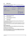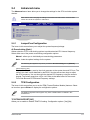
1
Motherboard
ITX-220
E4855
Second Edition V2
June 2009
Copyright © 2009 ASUSTeK Computer Inc. All Rights Reserved.
No part of this manual, including the products and software described in it, may be reproduced,
transmitted, transcribed, stored in a retrieval system, or translated into any language in any form or by any
means, except documentation kept by the purchaser for backup purposes, without the express written
permission of ASUSTeK Computer Inc. (“ASUS”).
Product warranty or service will not be extended if: (1) the product is repaired, modified or altered, unless
such repair, modification of alteration is authorized in writing by ASUS; or (2) the serial number of the
product is defaced or missing.
ASUS PROVIDES THIS MANUAL “AS IS” WITHOUT WARRANTY OF ANY KIND, EITHER EXPRESS
OR IMPLIED, INCLUDING BUT NOT LIMITED TO THE IMPLIED WARRANTIES OR CONDITIONS OF
MERCHANTABILITY OR FITNESS FOR A PARTICULAR PURPOSE. IN NO EVENT SHALL ASUS, ITS
DIRECTORS, OFFICERS, EMPLOYEES OR AGENTS BE LIABLE FOR ANY INDIRECT, SPECIAL,
INCIDENTAL, OR CONSEQUENTIAL DAMAGES (INCLUDING DAMAGES FOR LOSS OF PROFITS,
LOSS OF BUSINESS, LOSS OF USE OR DATA, INTERRUPTION OF BUSINESS AND THE LIKE),
EVEN IF ASUS HAS BEEN ADVISED OF THE POSSIBILITY OF SUCH DAMAGES ARISING FROM ANY
DEFECT OR ERROR IN THIS MANUAL OR PRODUCT.
SPECIFICATIONS AND INFORMATION CONTAINED IN THIS MANUAL ARE FURNISHED FOR
INFORMATIONAL USE ONLY, AND ARE SUBJECT TO CHANGE AT ANY TIME WITHOUT NOTICE,
AND SHOULD NOT BE CONSTRUED AS A COMMITMENT BY ASUS. ASUS ASSUMES NO
RESPONSIBILITY OR LIABILITY FOR ANY ERRORS OR INACCURACIES THAT MAY APPEAR IN THIS
MANUAL, INCLUDING THE PRODUCTS AND SOFTWARE DESCRIBED IN IT.
Products and corporate names appearing in this manual may or may not be registered trademarks or
copyrights of their respective companies, and are used only for identification or explanation and to the
owners’ benefit, without intent to infringe.
ii
Contents
Notices........................................................................................................... v
Safety information....................................................................................... vi
About this guide......................................................................................... vii
ITX-220 specifications summary.............................................................. viii
Chapter 1:
1.1
1.2
1.3
1.4
1.5
Motherboard overview.................................................................. 1-2
1.2.1
1.2.2
1.7
1.8
1.4.1
1.4.2
Memory configurations..................................................... 1-4
1.5.1
Installing an expansion card............................................ 1-6
1.5.3
PCI slot............................................................................ 1-6
Configuring an expansion card........................................ 1-6
Jumpers......................................................................................... 1-7
Connectors.................................................................................... 1-8
1.7.1
1.7.2
Rear panel connectors..................................................... 1-8
Internal connectors.......................................................... 1-9
Software support......................................................................... 1-14
1.8.1
Installing an operating system....................................... 1-14
Support DVD information............................................... 1-14
BIOS information
Managing and updating your BIOS............................................. 2-1
2.1.1
ASUS Update utility......................................................... 2-1
2.1.3
ASUS CrashFree BIOS 3 utility....................................... 2-3
2.1.2
2.3
Overview.......................................................................... 1-4
Expansion slot............................................................................... 1-6
Chapter 2:
2.2
Layout contents................................................................ 1-2
System memory............................................................................ 1-4
1.8.2
2.1
Motherboard layout.......................................................... 1-2
Central Processing Unit (CPU).................................................... 1-3
1.5.2
1.6
Product introduction
Before you proceed...................................................................... 1-1
ASUS EZ Flash 2 utility.................................................... 2-2
BIOS setup program..................................................................... 2-4
Main menu..................................................................................... 2-5
2.3.1
System Time.................................................................... 2-5
2.3.3
SATA 1/SATA 2..................................................................................2-5
2.3.2
System Date.................................................................... 2-5
iii
Contents
2.3.4
2.4
2.3.5
2.4.1
JumperFree Configuration............................................... 2-7
2.4.3
USB Configuration........................................................... 2-8
2.4.4
2.4.5
2.4.6
2.4.7
iv
Chipset............................................................................. 2-9
Onboard Devices Configuration..................................... 2-10
PCI PnP......................................................................... 2-10
Suspend Mode................................................................2-11
2.5.3
ACPI APIC Support.........................................................2-11
2.5.5
ACPI 2.0 Support............................................................2-11
APM Configuration......................................................... 2-12
Hardware Monitor.......................................................... 2-12
Boot menu................................................................................... 2-13
2.6.1
Boot Device Priority....................................................... 2-13
2.6.3
Security.......................................................................... 2-14
2.6.2
2.8
CPU Configuration........................................................... 2-9
2.5.1
2.5.4
2.7
TPM Configuration........................................................... 2-7
Power menu................................................................................. 2-11
2.5.2
2.6
System Information.......................................................... 2-6
Advanced menu............................................................................ 2-7
2.4.2
2.5
Storage Configuration...................................................... 2-6
Boot Settings Configuration........................................... 2-13
Tools menu.................................................................................. 2-16
2.7.1
2.7.2
AI NET 2........................................................................ 2-16
ASUS EZ Flash 2........................................................... 2-16
Exit menu..................................................................................... 2-16
Notices
Federal Communications Commission Statement
This device complies with Part 15 of the FCC Rules. Operation is subject to the following two
conditions:
•
•
This device may not cause harmful interference, and
This device must accept any interference received including interference that may cause
undesired operation.
This equipment has been tested and found to comply with the limits for a Class B digital
device, pursuant to Part 15 of the FCC Rules. These limits are designed to provide
reasonable protection against harmful interference in a residential installation. This
equipment generates, uses and can radiate radio frequency energy and, if not installed
and used in accordance with manufacturer’s instructions, may cause harmful interference
to radio communications. However, there is no guarantee that interference will not occur
in a particular installation. If this equipment does cause harmful interference to radio or
television reception, which can be determined by turning the equipment off and on, the user
is encouraged to try to correct the interference by one or more of the following measures:
•
Reorient or relocate the receiving antenna.
•
Connect the equipment to an outlet on a circuit different from that to which the receiver is
connected.
•
•
Increase the separation between the equipment and receiver.
Consult the dealer or an experienced radio/TV technician for help.
The use of shielded cables for connection of the monitor to the graphics card is required
to assure compliance with FCC regulations. Changes or modifications to this unit not
expressly approved by the party responsible for compliance could void the user’s authority
to operate this equipment.
Canadian Department of Communications Statement
This digital apparatus does not exceed the Class B limits for radio noise emissions from
digital apparatus set out in the Radio Interference Regulations of the Canadian Department
of Communications.
This class B digital apparatus complies with Canadian ICES-003.
REACH
Complying with the REACH (Registration, Evaluation, Authorisation, and Restriction of
Chemicals) regulatory framework, we published the chemical substances in our products at
ASUS REACH website at http://green.asus.com/english/REACH.htm.
DO NOT throw the motherboard in municipal waste. This product has been designed to
enable proper reuse of parts and recycling. This symbol of the crossed out wheeled bin
indicates that the product (electrical and electronic equipment) should not be placed in
municipal waste. Check local regulations for disposal of electronic products.
DO NOT throw the mercury-containing button cell battery in municipal waste. This symbol
of the crossed out wheeled bin indicates that the battery should not be placed in municipal
waste.
Safety information
Electrical safety
•
•
•
•
•
•
•
To prevent electric shock hazard, disconnect the power cable from the electric outlet
before relocating the system.
When adding or removing devices to or from the system, ensure that the power cables
for the devices are unplugged before the signal cables are connected. If possible,
disconnect all power cables from the existing system before you add a device.
Before connecting or removing signal cables from the motherboard, ensure that all
power cables are unplugged.
Seek professional assistance before using an adapter or extension cord. These devices
could interrupt the grounding circuit.
Ensure that your power supply is set to the correct voltage in your area. If you are not
sure about the voltage of the electrical outlet you are using, contact your local power
company.
If the power supply is broken, do not try to fix it by yourself. Contact a qualified service
technician or your retailer.
The optical S/PDIF is an optional component (may or may not be included in your
motherboard) and is defined as a CLASS 1 LASER PRODUCT.
INVISIBLE LASER RADIATION, AVOID EXPOSURE TO BEAM.
•
•
•
Never dispose of the battery in fire. It could explode and release harmful substances into
the environment.
Never dispose of the battery with your regular household waste. Take it to a hazardous
material collection point.
Never replace the battery with an incorrect battery type.
• RISK OF EXPLOSION IF BATTERY IS REPLACED BY AN INCORRECT TYPE.
• DISPOSE OF USED BATTERIES ACCORDING TO THE ABOVE BATTERY-RELATED
INSTRUCTIONS.
Operation safety
•
•
•
•
•
•
vi
Before installing the motherboard and adding devices on it, carefully read all the manuals
that came with the package.
Before using the product, ensure that all cables are correctly connected and the power
cables are not damaged. If you detect any damage, contact your dealer immediately.
To avoid short circuits, keep paper clips, screws, and staples away from connectors,
slots, sockets and circuitry.
Avoid dust, humidity, and temperature extremes. Do not place the product in any area
where it may become wet.
Place the product on a stable surface.
If you encounter technical problems with the product, contact a qualified service
technician or your retailer.
About this guide
This user guide contains the information you need when installing and configuring the
motherboard.
How this guide is organized
This guide contains the following parts:
• Chapter 1: Product introduction
•
This chapter describes the features of the motherboard and the new technology it
supports.
Chapter 2: BIOS information
This chapter tells how to change system settings through the BIOS Setup menus.
Detailed descriptions of the BIOS parameters are also provided.
Conventions used in this guide
To ensure that you perform certain tasks properly, take note of the following symbols used
throughout this manual.
DANGER/WARNING: Information to prevent injury to yourself when trying to complete a task.
CAUTION: Information to prevent damage to the components when trying to complete a task.
IMPORTANT: Instructions that you MUST follow to complete a task.
NOTE: Tips and additional information to help you complete a task.
Where to find more information
Refer to the following sources for additional information and for product and software
updates.
1.
ASUS websites
The ASUS website provides updated information on ASUS hardware and software
products. Refer to the ASUS contact information.
2.
Optional documentation
Your product package may include optional documentation, such as warranty flyers,
that may have been added by your dealer. These documents are not part of the
standard package.
Typography
Bold text
Italics
<Key>
<Key1>+<Key2>+<Key3>
Indicates a menu or an item to select.
Used to emphasize a word or a phrase.
Keys enclosed in the less-than and greater-than sign means
that you must press the enclosed key.
Example: <Enter> means that you must press the Enter or
Return key.
If you must press two or more keys simultaneously, the key
names are linked with a plus sign (+).
Example: <Ctrl>+<Alt>+<D>
vii
ITX-220 specifications summary
CPU
Chipset
CPU Fan
Front Side Bus
Memory
Graphics
Expansion slot
Storage
Audio
LAN
USB
ASUS special features
Rear panel ports
Integrated Intel® Celeron® 220 processor
Supports Intel® EM64T technology
Northbridge: Intel® 945GC
Southbridge: Intel® ICH7
Fan Dimensions: 40 x 40 x10mm
Rated Speed: 5000 ± 10% RPM
Rated Voltage: DC 12V
Maximum Air Flow: 5.57 CFM
Noise Level: 25.3 dBA (Max. 27.5 dBA)
533 MHz
Dual channel memory architecture
- 2 x 240-pin DIMM sockets support unbuffered
non-ECC 533 MHz DDR2 memory modules
- Supports up to 4GB system memory
* Refer to www.asus.com or this user manual for the
Memory QVL (Qualified Vendors Lists).
** When you install a total memory of 4GB capacity
or more, Windows® 32-bit operating system may only
recognize less than 3GB. We recommend a maximum
of 3GB system memory if you are using a Windows®
32-bit operating system.
Integrated Intel® Graphics Media Accelerator 950
Supports D-Sub with max. resolution of 2048 x 1536 x
32 Bpp @75Hz
Maximum shared memory of 224MB
1 x PCI slot
Intel® ICH7 SouthBridge supports:
- 2 x Serial ATA 3Gb/s ports
VIA VT1705 High Definition Audio 6-channel CODEC
Realtek® PCIe Gb LAN controller
Supports up to 6 USB 2.0/1.1 ports (2 ports at mid-board,
4 ports at back panel)
ASUS CrashFree BIOS 3
ASUS EZ Flash 2
ASUS MyLogo 2™
ASUS AI NET 2
1 x PS/2 keyboard port
1 x PS/2 mouse port
1 x VGA port
1 x COM port
1 x LAN (RJ-45) port
4 x USB 2.0 ports
6-channel audio I/O ports
(continued on the next page)
viii
ITX-220 specifications summary
Internal connectors
BIOS features
Accessories
Support DVD contents
Form Factor
1 x USB connector supports additional 2 USB ports
1 x Speaker connector
2 x Serial ATA connectors
1 x Chassis fan connector
1 x Chassis intrusion connector
1 x CPU fan connector
1 x TPM connector (optional)
1 x System panel connector
1 x High definition front panel audio connector
1 x 24-pin EATX power connector
1 x 4-pin ATX 12V power connector
8 Mb Flash ROM, AMI BIOS, PnP, DMI v2.0, WfM 2.0,
SMBIOS 2.5, ACPI v2.0a
1 x Serial ATA cable
1 x I/O shield
Drivers
ASUS PC Probe II
ASUS Update
Anti-virus software (OEM version)
User Manual
Mini ITX form factor: 6.75 in x 6.75 in (17.1cm x 17.1cm)
*Specifications are subject to change without notice.
ix
Chapter 1
Product introduction
Thank you for buying an ASUS® ITX-220 motherboard!
Before you start installing the motherboard, and hardware devices on it, check the items in
your motherboard package. Refer to page ix for the list of accessories.
If any of the items is damaged or missing, contact your retailer.
1.1
Before you proceed
Take note of the following precautions before you install motherboard components or change
any motherboard settings.
• Unplug the power cord from the wall socket before touching any component.
• Before handling components, use a grounded wrist strap or touch a safely grounded
object or a metal object, such as the power supply case, to avoid damaging them due to
static electricity.
• Hold components by the edges to avoid touching the ICs on them.
• Whenever you uninstall any component, place it on a grounded antistatic pad or in the
bag that came with the component.
• Before you install or remove any component, ensure that the ATX power supply is
switched off or the power cord is detached from the power supply. Failure to do so may
cause severe damage to the motherboard, peripherals, or components.
Onboard LED
The motherboard comes with a standby power LED that lights up to indicate that the system
is ON, in sleep mode, or in soft-off mode. This is a reminder that you must shut down
the system and unplug the power cable before removing or plugging in any motherboard
component. The illustration below shows the location of the onboard LED.
ASUS ITX-220
1-1
1.2
Motherboard overview
1.2.1
Motherboard layout
Ensure that you install the motherboard into the chassis in the correct orientation. The edge
with external ports goes to the rear part of the chassis.
Place this side towards
the rear of the chassis.
Place four screws into the holes indicated by circles to secure the motherboard to the
chassis. DO NOT overtighten the screws! Doing so can damage the motherboard.
1.2.2
1-2
Layout contents
Connectors/Jumpers/Slots/LED
Page
Connectors/Jumpers/Slots/LED
Page
1.
Keyboard/mouse power (3-pin PS2_USBPW1-6)
1-7
8.
Standby power LED (SB_PWR)
1-1
2.
ATX power connectors (24-pin EATXPWR, 4-pin
ATX12V)
1-9
9.
System panel connector (10-1 pin
F_PANEL)
1-12
3.
Speaker connector (4-pin SPEAKER)
1-10
10.
Clear RTC RAM (3-pin CLRTC)
1-7
4.
USB connector (10-1 pin USB56)
1-10
11.
Chassis intrusion connector (4-1 pin
CHASSIS)
1-11
5.
CPU Socket
1-3
12.
PCI slot
1-6
6.
CPU and chassis fan connectors (3-pin
CPU_FAN, 3-pin CHA_FAN)
1-11
13.
Serial ATA connectors (7-pin SATA1,
SATA2)
1-13
7.
DDR2 DIMM slots
1-4
14.
Front panel audio connector (10-1 pin
AAFP)
1-13
Chapter 1: Product introduction
1.3
Central Processing Unit (CPU)
The motherboard comes with an onboard Intel® Celeron® 220 processor and a specially
designed CPU heatsink and fan.
Ensure that the CPU fan cable is connected to the onboard CPU_Fan connector.
ASUS ITX-220
1-3
1.4
System memory
1.4.1
Overview
The motherboard comes with two Double Data Rate 2 (DDR2) Dual Inline Memory Modules
(DIMM) sockets. The figure illustrates the location of the DDR2 DIMM sockets:
1.4.2
Channel
Sockets
Channel A
DIMM_A1
Channel B
DIMM_B1
Memory configurations
You may install 512MB, 1GB and 2GB unbuffered non‑ECC DDR2 DIMMs into the DIMM
sockets.
• You may install varying memory sizes in Channel A and Channel B. The system maps
the total size of the lower-sized channel for the dual-channel configuration. Any excess
memory from the higher-sized channel is then mapped for the single-channel operation.
• Always install DIMMs with the same CAS latency. For optimum compatibility, it is
recommended that you obtain memory modules from the same vendor.
• Due to the memory address limitation on 32-bit Windows® OS, when you install 4GB
or more memory on the motherboard, the actual usable memory for the OS can be
about 3GB or less. For effective use of memory, we recommend that you do any of the
following:
-
-
Use a maximum of 3GB system memory if you are using a 32-bit Windows® OS.
Install a 64-bit Windows® OS when you want to install 4GB or more memory on the motherboard.
• This motherboard does not support DIMMs made up of 256 megabits (Mb) chips or less.
This motherboard supports up to 4GB on Windows® XP Professional x64 and Windows®
Vista x64 editions. You may install a maximum of 2GB DIMMs on each slot.
1-4
Chapter 1: Product introduction
ITX-220 Motherboard Qualified Vendors Lists (QVL)
DDR2-533 MHz capability
DIMM socket
support
(Optional)
Size
Vendor
Part No.
SS/DS
CL
Chip No.
Chip Brand
512MB
Corsair
VS 512MB533D2
SS
N/A
64M8CEDGPS0900805
Corsair
·
512MB
Corsair
VS 512MB533D2
DS
N/A
MIII0052532M8CEC
Corsair
·
1024MB
Corsair
VS1GB533D2
DS
N/A
64M8CFEGQIB0900718
Corsair
·
512MB
Elpida
EBE51UD8ABFA-5C-E
SS
N/A
E5108AB-5C-E
Elpida
·
512MB
Kingmax
KLBC28F-A8KB4
SS
N/A
KKEA88B4IAK-37
Kingmax
·
·
2048MB
Aeneon
AET860UD00-370A08X
DS
N/A
AET03F370AFVV26176G 0542
AENEON
·
·
1024MB
Elixir
M2Y1G64TU8HBOB-37B
DS
N/A
N2TU 51280BE-37B61921300CP
Elixir
·
·
512MB
REMAXEL
RML1040EG38D6F-533
SS
N/A
E5108AG-5C-E
Elpida
·
·
512MB
TAKEMS
TMS51B264C081-534AE
SS
N/A
MS18T 51280-3.7EA07100
takeMS
·
512MB
TAKEMS
TMS51B264C081-534AP
SS
N/A
MS18T 51280-3.7P0704D
takeMS
·
·
512MB
TAKEMS
TMS51B264C081-534QI
SS
N/A
MS18T 51280-3.7
takeMS
·
·
1024MB
TAKEMS
TMS1GB264C081-534AE
DS
N/A
MS18T 51280-3.7EA0651D
takeMS
·
·
1024MB
TAKEMS
TMS1GB264C081-534AP
DS
N/A
MS18T 51280-3.7P0645D
takeMS
·
·
1024MB
TAKEMS
TMS1GB264C081-534QI
DS
N/A
MS18T 51280-3.7
takeMS
·
·
A*
B*
·
SS: Single-sided / DS: Double-sided
DIMM support:
• A*: Supports one module inserted into either slot as the single-channel memory
configuration.
• B*: Supports one pair of modules inserted into both the blue slots as one pair of
dual-channel memory configuration.
Visit the ASUS website at www.asus.com for the latest QVL.
ASUS ITX-220
1-5
1.5
Expansion slot
In the future, you may need to install expansion cards. The following sub‑sections describe
the slot and the expansion cards that it supports.
Unplug the power cord before adding or removing expansion cards. Failure to do so may
cause you physical injury and damage motherboard components.
1.5.1
Installing an expansion card
To install an expansion card:
1.
Before installing the expansion card, read the documentation that came with it and
make the necessary hardware settings for the card.
2.
Remove the system unit cover (if your motherboard is already installed in a chassis).
3.
Remove the bracket opposite the slot that you intend to use. Keep the screw for later
use.
4.
Align the card connector with the slot and press firmly until the card is completely
seated on the slot.
5.
Secure the card to the chassis with the screw you removed earlier.
6.
Replace the system cover.
1.5.2
Configuring an expansion card
After installing the expansion card, configure it by adjusting the software settings.
1.
Turn on the system and change the necessary BIOS settings, if any. See Chapter 2 for
information on BIOS setup.
2.
Assign an IRQ to the card.
3.
Install the software drivers for the expansion card.
1.5.3
PCI slot
The PCI slot supports cards such as a LAN card, SCSI card, USB card, and other cards that
comply with PCI specifications.
1-6
Chapter 1: Product introduction
1.6
1.
Jumpers
Clear RTC RAM (3-pin CLRTC)
This jumper allows you to clear the Real Time Clock (RTC) RAM in CMOS. You can
clear the CMOS memory of date, time, and system setup parameters by erasing
the CMOS RTC RAM data. The onboard button cell battery powers the RAM data in
CMOS, which include system setup information such as system passwords.
To erase the RTC RAM:
1. Turn OFF the computer and unplug the power cord.
2. Move the jumper cap from pins 1-2 (default) to pins 2-3. Keep the cap on pins 2-3
for about 5-10 seconds, then move the cap back to pins 1-2.
3. Plug the power cord and turn ON the computer.
4. Hold down the <Del> key during the boot process and enter BIOS setup to re-enter
data.
Except when clearing the RTC RAM, never remove the cap on CLRTC jumper default
position. Removing the cap will cause system boot failure!
If the steps above do not help, remove the onboard battery and move the jumper again to
clear the CMOS RTC RAM data. After clearing the CMOS, reinstall the battery.
2.
Keyboard/mouse power (3-pin PS2_USBPW1-6)
This jumper allows you to enable or disable the keyboard/mouse and USB port 1-6
wake-up feature. When you set this jumper to pins 2-3 (+5VSB), you can wake up the
computer by pressing a key on the keyboard (the default is the Space Bar), clicking
the mouse, or using a USB device. This feature requires an ATX power supply that can
supply at least 1A on the +5VSB lead, and a corresponding setting in the BIOS.
ASUS ITX-220
1-7
1.7
Connectors
1.7.1
Rear panel connectors
1.
PS/2 mouse port (green). This port is for a PS/2 mouse.
2.
LAN (RJ-45) port. This port allows Gigabit connection to a Local Area Network (LAN)
through a network hub. Refer to the table below for the LAN port LED indications.
LAN port LED indications
ACT/LINK LED
ACT/LINK SPEED
LED
LED
SPEED LED
Status
Description
Status
Description
OFF
No link
OFF
10 Mbps connection
ORANGE
Linked
ORANGE
100 Mbps connection
BLINKING
Data activity
GREEN
1 Gbps connection
LAN port
3.
Line In port (light blue). This port connects the tape, CD, DVD player, or other audio
sources.
4.
Line Out port (lime). This port connects a headphone or a speaker. In 4-channel and
6-channel configurations, the function of this port becomes Front Speaker Out.
5.
Microphone port (pink). This port connects a microphone.
Refer to the audio configuration table below for the function of the audio ports in 2, 4, or
6-channel configuration.
Audio 2, 4, or 6-channel configuration
Port
Headset 2-channel
4-channel
6-channel
Line In
Rear Speaker Out
Rear Speaker Out
Lime
Line Out
Front Speaker Out
Front Speaker Out
Pink
Mic In
Mic In
Bass/Center
Light Blue
1-8
Chapter 1: Product introduction
6.
USB 2.0 ports 1 and 2. These two 4-pin Universal Serial Bus (USB) ports are
available for connecting USB 2.0 devices.
7.
USB 2.0 ports 3 and 4. These two 4-pin Universal Serial Bus (USB) ports are
available for connecting USB 2.0 devices.
8.
Video Graphics Adapter (VGA) port. This 15-pin port is for a VGA monitor or other
VGA-compatible devices.
9.
COM port. This port is for pointing devices or other serial devices.
10. PS/2 keyboard port (purple). This port is for a PS/2 keyboard.
1.7.2
1.
Internal connectors
ATX power connectors (24-pin EATXPWR, 4-pin ATX12V)
These connectors are for ATX power supply plugs. The power supply plugs are
designed to fit these connectors in only one orientation. Find the proper orientation and
push down firmly until the connectors completely fit.
• For a fully configured system, we recommend that you use a power supply unit (PSU)
that complies with ATX 12 V Specification 2.0 (or later version) and provides a minimum
power of 400 W.
• Do not forget to connect the 4-pin ATX12V power plug. Otherwise, the system will not
boot.
• We recommend that you use a PSU with a higher power output when configuring a
system with more power-consuming devices or when you intend to install additional
devices. The system may become unstable or may not boot up if the power is
inadequate.
ASUS ITX-220
1-9
2.
USB connector (10-1 pin USB56)
This connector is for a USB 2.0 port. Connect the USB module cable to this connector,
then install the module to a slot opening at the back of the system chassis. This USB
connector complys with USB 2.0 specification that supports up to 480 Mbps connection
speed.
Never connect a 1394 cable to the USB connector. Doing so will damage the motherboard!
The USB module cable is purchased separately.
3.
1-10
Speaker connector (4-pin SPEAKER)
This 4-pin connector is for the chassis-mounted system warning speaker. The speaker
allows you to hear system beeps and warnings.
Chapter 1: Product introduction
4.
CPU and chassis fan connectors (3-pin CPU_FAN, 3-pin CHA_FAN)
The fan connectors support cooling fans of 350 mA~2000 mA (24 W max.) or a total of
1 A~3.48 A (41.76 W max.) at +12V. Connect the fan cables to the fan connectors on
the motherboard, ensuring that the black wire of each cable matches the ground pin of
the connector.
Do not forget to connect the fan cables to the fan connectors. Insufficient air flow inside the
system may damage the motherboard components. These are not jumpers! Do not place
jumper caps on the fan connectors!
5.
Chassis intrusion connector (4-1 pin CHASSIS)
This connector is for a chassis-mounted intrusion detection sensor or switch. Connect
one end of the chassis intrusion sensor or switch cable to this connector. The chassis
intrusion sensor or switch sends a high-level signal to this connector when a chassis
component is removed or replaced. The signal is then generated as a chassis intrusion
event.
By default, the pin labeled “Chassis Signal” and “Ground” are shorted with a jumper
cap. Remove the jumper caps only when you intend to use the chassis intrusion
detection feature.
ASUS ITX-220
1-11
6.
•
•
•
•
1-12
System panel connector (10-1 pin F_PANEL)
This connector supports several chassis-mounted functions.
System power LED (2-pin PLED)
This 2-pin connector is for the system power LED. Connect the chassis power LED
cable to this connector. The system power LED lights up when you turn on the system
power, and blinks when the system is in sleep mode.
Hard disk drive activity LED (2-pin HD_LED)
This 2-pin connector is for the HDD Activity LED. Connect the HDD Activity LED cable
to this connector. The HD LED lights up or flashes when data is read from or written to
the HDD.
ATX power button/soft-off button (2-pin PWRBTN)
This connector is for the system power button. Pressing the power button turns
the system on or puts the system in sleep or soft-off mode depending on the BIOS
settings. Pressing the power switch for more than four seconds while the system is ON
turns the system OFF.
Reset button (2-pin RESET)
This 2-pin connector is for the chassis-mounted reset button for system reboot without
turning off the system power.
Chapter 1: Product introduction
7.
8.
Serial ATA connectors (7-pin SATA1, SATA2)
These connectors are for the Serial ATA signal cables for Serial ATA 3Gb/s hard disk
drives and optical disk drives. The Serial ATA 3Gb/s is backward compatible with the
Serial ATA 1.5Gb/s specification. The data transfer rate of the Serial ATA 3Gb/s is faster
than the standard parallel ATA (133 Mb/s).
Front panel audio connector (10-1 pin AAFP)
This connector is for a chassis-mounted front panel audio I/O module that supports
either HD Audio or legacy AC`97 audio standard. Connect one end of the front panel
audio I/O module cable to this connector.
• We recommend that you connect a high-definition front panel audio module to this
connector to avail of the motherboard’s high-definition audio capability.
• If you want to connect a high-definition front panel audio module to this connector, set
the Front Panel Support Type item in the BIOS setup to [HD Audio]. If you want to
connect an AC'97 front panel audio module to this connector, set the item to [AC97]. By
default, this connector is set to [HD Audio]. See section 2.4.5 Chipset for details.
ASUS ITX-220
1-13
1.8
Software support
1.8.1
Installing an operating system
This motherboard supports Windows® XP/Vista Operating Systems (OS). Always install the
latest OS version and corresponding updates to maximize the features of your hardware.
• Motherboard settings and hardware options vary. Refer to your OS documentation for
detailed information.
• Ensure that you install Windows® XP Service Pack 3 or later versions / Windows® Vista
Service Pack 1 or later versions before installing the drivers for better compatibility and
system stability.
1.8.2
Support DVD information
The Support DVD that comes with the motherboard package contains the drivers, software
applications, and utilities that you can install to avail all motherboard features.
The contents of the Support DVD are subject to change at any time without notice. Visit the
ASUS website at www.asus.com for updates.
To run the Support DVD
Place the Support DVD to the optical drive. The DVD automatically displays the Drivers menu
if Autorun is enabled in your computer.
The following screen is for reference only.
Click an icon to
display Support DVD/
motherboard information
Click an item to install
If Autorun is NOT enabled in your computer, browse the contents of the Support DVD to
locate the file ASSETUP.EXE from the BIN folder. Double-click the ASSETUP.EXE to run
the DVD.
1-14
Chapter 1: Product introduction
Chapter 2
BIOS information
2.1
Managing and updating your BIOS
Save a copy of the original motherboard BIOS file to a USB flash disk in case you need to
restore the BIOS in the future. Copy the original motherboard BIOS using the ASUS Update
utility.
2.1.1
ASUS Update utility
The ASUS Update is a utility that allows you to manage, save, and update the motherboard
BIOS in Windows® environment.
• ASUS Update requires an Internet connection either through a network or an Internet
Service Provider (ISP).
• This utility is available in the support DVD that comes with the motherboard package.
Installing ASUS Update
To install ASUS Update:
1.
Place the support DVD in the optical drive. The Drivers menu appears.
2.
Click the Utilities tab, then click ASUS Update.
3.
Follow the onscreen instructions to complete the installation.
Quit all Windows® applications before you update the BIOS using this utility.
Updating the BIOS
To update the BIOS:
1.
From the Windows® desktop, click Start > Programs > ASUS > ASUSUpdate >
ASUSUpdate to launch the ASUS Update utility.
2.
From the dropdown list, select any of the updating process:
ASUS ITX-220
2-1
Updating from the Internet
a.
Select Update BIOS from the Internet, then click Next.
b.
Select the ASUS FTP site nearest you to avoid network traffic, or click Auto Select then click Next.
c.
From the FTP site, select the BIOS version that you wish to download then click Next.
The ASUS Update utility is capable of updating itself through the Internet. Always update
the utility to avail all its features.
Updating from a BIOS file
a.
Select Update BIOS from a file, then click Next.
b.
Locate the BIOS file from the Open window, then click Open.
3.
Follow the onscreen instructions to complete the updating process.
2.1.2
ASUS EZ Flash 2 utility
The ASUS EZ Flash 2 feature allows you to update the BIOS without using an OS‑based
utility.
Before you start using this utility, download the latest BIOS file from the ASUS website at
www.asus.com.
To update the BIOS using EZ Flash 2:
1.
Insert the USB flash disk that contains the latest BIOS file to the USB port, then launch
EZ Flash 2 in any of these two ways:
•
Press <Alt> + <F2> during POST to display the following:
ASUSTek EZ Flash 2 BIOS ROM Utility V3.36
FLASH TYPE: WOINBOND W25X80
Current ROM
BOARD: ITX-220
VER: 0209 (H:00 B:05)
DATE: 04/01/2009
Update ROM
BOARD: Unknown
VER: Unknown
DATE: Unknown
PATH: A:\
A:
Note
[Enter] Select or Load [Tab] Switch
[Up/Down/Home/End] Move
[B] Backup
2-2
[V] Drive Info
[ESC] Exit
Chapter 2: BIOS information
•
2.
Enter the BIOS setup program. Go to the Tools menu to select EZ Flash 2 and
press <Enter> to enable it.
Press <Tab> to switch between drives until the correct BIOS file is found.
When the correct BIOS file is found, EZ Flash 2 performs the BIOS update process
and automatically reboots the system when done.
• Only a USB flash disk with FAT 32/16 format and single partition can support the ASUS
EZ Flash 2 utility.
• Do not shut down or reset the system while updating the BIOS to prevent system boot
failure!
2.1.3
ASUS CrashFree BIOS 3 utility
The ASUS CrashFree BIOS 3 is an auto recovery tool that allows you to restore the BIOS file
when it fails or gets corrupted during the updating process. You can update a corrupted BIOS
file using the motherboard support DVD or a USB flash disk that contains the updated BIOS
file.
• Prepare the motherboard support DVD or the USB flash disk containing the updated
motherboard BIOS before using this utility.
• Always connect the SATA cable to the SATA1 / SATA 2 connector. Otherwise, the utility
will not function.
Recovering the BIOS
To recover the BIOS:
1.
Turn on the system.
2.
Insert the support DVD or USB flash disk containing the BIOS file to the optical drive or
USB port.
3.
The utility displays the following message and automatically checks the support DVD
or USB flash disk for the BIOS file.
Bad BIOS checksum. Starting BIOS recovery...
Checking for CD-ROM...
CD-ROM not found!
Checking for USB Device...
When found, the utility reads the BIOS file and starts erasing the corrupted BIOS file.
Bad BIOS checksum. Starting BIOS recovery...
Checking for USB Device...
USB Device found.
Reading file “ITX220.ROM”. Completed.
Start Erasing...\
ASUS ITX-220
2-3
4.
Restart the system after the utility completes the updating process.
• Only a USB flash disk with FAT 32/16 format and single partition can support ASUS
CrashFree BIOS 3. The device size should be smaller than 8GB.
• DO NOT shut down or reset the system while updating the BIOS! Doing so can cause
system boot failure!
The recovered BIOS may not be the latest BIOS version for this motherboard. Download
the latest BIOS file from the ASUS website at www.asus.com.
2.2
BIOS setup program
Use the BIOS Setup program when you are installing a motherboard, reconfiguring your
system, or prompted to “Run Setup.” This section explains how to configure your system
using this utility.
If you wish to enter Setup after POST, reboot the system by doing any of the following
procedures:
• Restart using the OS standard shutdown procedure.
•
Press <Ctrl>+<Alt>+<Del> simultaneously.
•
Press the power button to turn the system off then back on.
•
Press the reset button on the system chassis.
Using the power button, reset button, or the <Ctrl>+<Alt>+<Del> keys to force reset from
a running operating system can cause damage to your data or system. We recommend to
always shut down the system properly from the operating system.
• The default BIOS settings for this motherboard apply for most conditions to ensure
optimum performance. If the system becomes unstable after changing any BIOS
settings, load the default settings to ensure system compatibility and stability. Select the
Load Setups Default item under the Exit Menu. See section 2.8 Exit Menu.
• The BIOS setup screens shown in this section are for reference purposes only, and may
not exactly match what you see on your screen.
• Visit the ASUS website at www.asus.com to download the latest BIOS file for this
motherboard.
2-4
Chapter 2: BIOS information
2.3
Main menu
When you enter the BIOS Setup program, the Main menu screen appears, giving you an
overview of the basic system information.
Main
Advanced
Power
BIOS SETUP UTILITY
Boot
Tools
Exit
System Time
System Date
SATA 1
SATA 2
[00:31:48]
[Mon 01/21/2002]
Use [ENTER], [TAB] or
[SHIFT-TAB] to select
a field.
[Not Detected]
[Not Detected]
Use [+] or [-] to
configure system time.
Storage Configuration
System Information
+-
Tab
F1
F10
ESC
Select Screen
Select Item
Change Field
Select Field
General Help
Save and Exit
Exit
v02.58 (C)Copyright 1985-2009, American Megatrends, Inc.
2.3.1
System Time [xx:xx:xx]
2.3.2
System Date [Day xx/xx/xxxx]
2.3.3
SATA 1/SATA 2
Allows you to set the system time.
Allows you to set the system date.
While entering Setup, the BIOS automatically detects the presence of SATA devices. There
is a separate sub-menu for each SATA device. Select a device item then press <Enter> to
display the SATA device information.
The BIOS automatically detects the values opposite the dimmed items (Device, Vendor, Size,
LBA Mode, Block Mode, PIO Mode, Async DMA, Ultra DMA, and SMART Monitoring). These
values are not user-configurable. These items show N/A if no Serial ATA device is installed in
the system.
LBA/Large Mode [Auto]
Enables or disables the LBA mode. Setting to [Auto] enables the LBA mode if the device
supports this mode, and if the device was not previously formatted with LBA mode disabled.
Configuration options: [Disabled] [Auto]
Block (Multi-sector Transfer) M [Auto]
Enables or disables data multi-sectors transfers. When set to [Auto], the data transfer from
and to the device occurs multiple sectors at a time if the device supports multi-sector transfer
feature. When set to [Disabled], the data transfer from and to the device occurs one sector
at a time. Configuration options: [Disabled] [Auto]
ASUS ITX-220
2-5
PIO Mode [Auto]
Selects the PIO mode. Configuration options: [Auto] [0] [1] [2] [3] [4]
DMA Mode [Auto]
Selects the DMA mode. Configuration options: [Auto]
SMART Monitoring [Auto]
Sets the Smart Monitoring, Analysis, and Reporting Technology.
Configuration options: [Auto] [Disabled] [Enabled]
32Bit Data Transfer [Enabled]
Enables or disables 32-bit data transfer. Configuration options: [Disabled] [Enabled]
2.3.4
Storage Configuration
The items in this menu allow you to set or change the configurations for the SATA devices
installed in the system. Select an item then press <Enter> if you want to configure the item.
SATA Operate Mode [Enhanced Mode]
Disables or allows selection of the SATA operation mode depending on the operating
system (OS) that you installed. Set to [Enhanced Mode] if you are using a native OS, such as
Windows® 2000/XP. Configuration options: [Disabled] [Compatible Mode] [Enhanced Mode]
2.3.5
System Information
This menu gives you an overview of the general system specifications. The BIOS
automatically detects the items in this menu.
AMI BIOS
Displays the auto-detected BIOS information.
Processor
Displays the auto-detected CPU specification.
System Memory
Displays the auto-detected system memory.
2-6
Chapter 2: BIOS information
2.4
Advanced menu
The Advanced menu items allow you to change the settings for the CPU and other system
devices.
Take caution when changing the settings of the Advanced menu items. Incorrect field
values can cause the system to malfunction.
Main
Advanced
Power
BIOS SETUP UTILITY
Boot
Tools
Exit
JumperFree Configuration
TPM Configuration
USB Configuration
Adjust System
frequency/voltage.
CPU Configuration
Chipset
Onboard Devices Configuration
PCIPnP
2.4.1
JumperFree Configuration
The items in this menu allows you to adjust the system frequency/voltage.
Ai Overclocking [Auto]
Allows selection of CPU overclocking options to achieve desired CPU internal frequency.
Select either one of the preset overclocking configuration options:
Manual - allows you to individually set overclocking parameters.
Auto - loads the optimal settings for the system.
The following item appears only when you set the AI Overclocking item to [Manual].
CPU Frequency [xxx]
Displays the frequency sent by the clock generator to the system bus and PCI bus. The
value of this item is auto-detected by the BIOS. Use the <+> and <-> keys to adjust
the CPU frequency. You can also type the desired CPU frequency using the numeric
keypad. The values range from 133 to 140. Refer to the table below for the correct
Front Side Bus and CPU External Frequency settings.
2.4.2
TPM Configuration
The items in this menu allow you to set the TPM (Trusted Platform Module) features. Select
an item then press <Enter> to display the configuration options.
The TPM Configuration item appears only when a TPM module is installed in this
motherboard.
TCG/TPM SUPPORT [NO]
Allows you to enable or disable TPM/TCG setting. Configuration options: [Yes] [No]
ASUS ITX-220
2-7
The following two items appear only when you set the TCG/TPM SUPPORT item to [Yes].
TPM Enable/Disable Status [No State]
This item is not user-configurable.
TPM Owner Status [No State]
This item is not user-configurable.
2.4.3
USB Configuration
The items in this menu allows you to change the USB-related features. Select an item then
press <Enter> to display the configuration options.
The Module Version and USB Devices Enabled items show the auto-detected values. If no
USB device is detected, the item shows None.
USB Functions [Enabled]
Allows you to disable or enable the USB functions.
Configuration options: [Disabled] [Enabled]
Legacy USB Support [Auto]
Allows you to enable or disable support for Legacy USB storage devices, including USB flash
drives and USB hard drives. Setting to [Auto] allows the system to detect the presence of
USB devices at startup. If detected, the USB controller legacy mode is enabled. If no USB
device is detected, the legacy USB support is disabled.
Configuration options: [Disabled] [Enabled] [Auto]
USB 2.0 Controller [Enabled]
Allows you to enable or disable USB 2.0 controller.
Configuration options: [Enabled] [Disabled]
USB 2.0 Controller Mode [HiSpeed]
Allows you to configure the USB 2.0 controller in HiSpeed (480Mbps) or Full Speed
(12Mbps). Configuration options: [FullSpeed] [HiSpeed]
The following items may only appear when a USB storage device is plugged.
USB Mass Storage Device Configuration
USB Mass Storage Reset Delay [20 Sec]
Allows you to set the maximum time that the BIOS waits for the USB storage device to
initialize. Configuration options: [10 Sec] [20 Sec] [30 Sec] [40 Sec]
Emulation Type [Auto]
Allows you to select the emulation type. Configuration options: [Auto] [Floppy] [Forced
FDD] [Hard Disk] [CDROM]
2-8
Chapter 2: BIOS information
2.4.4
CPU Configuration
The items in this menu show the CPU-related information that the BIOS automatically
detects.
Max CPUID Value Limit [Disabled]
Allows you to determine whether to limit CPUID maximum value. Set this item to [Disabled]
for Windows XP operating system; set this item to [Enabled] for legacy operating system
such as Windows NT4.0. Configuration options: [Disabled] [Enabled]
CPU TM function [Enabled]
Enables or disables Intel® CPU Thermal Monitor (TM) function, a CPU overheating protection
function. When enabled, the CPU core frequency and voltage are reduced when the CPU
overheats. Configuration options: [Disabled] [Enabled]
Execute Disable Bit [Enabled]
Allows you to enable or disable the No-Execution Page Protection Technology. Setting this
item to [Disabled] forces the XD feature flag to always return to zero (0). Configuration
options: [Disabled] [Enabled]
2.4.5
Chipset
The Chipset menu allows you to change the advanced chipset settings. Select an item then
press <Enter> to display the submenu.
North Bridge Configuration
Configure DRAM Timing by SPD [Enabled]
Allows you to enable or disable configuring the DRAM Timing by SPD.
Configuration options: [Enabled] [Disabled]
Boot Graphic Adapter Priority [PCI/Int-VGA]
Allows selection of the graphics controller to use as primary boot device.
Configuration options: [Internal VGA] [PCI/Int-VGA]
Internal Graphics Mode Select [Enabled, 8MB]
Allows you to select the amount of system memory used by the internal graphics device.
Configuration options: [Disabled] [Enabled, 1MB] [Enabled, 8MB]
DVMT Mode Select [DVMT Mode]
Allows you to select the graphics memory type.
Configuration options: [Fixed Mode] [DVMT Mode] [Combo Mode]
DVMT/FIXED Memory [128MB]
Allows you to select the amount of the DVMT/FIXED memory.
Configuration options: [64MB] [128MB] [Maximum DVMT]
South Bridge Configuration
HD Audio Controller [Enabled]
Allows you to enable or disable the high definition audio controller.
Configuration options: [Enabled] [Disabled]
ASUS ITX-220
2-9
Front Panel Support Type [HD Audio]
Allows you to select the front panel support type. If High Definition Audio Front Panel
used, please set HD Audio mode. Configuration options: [AC97] [HD Audio]
2.4.6
Onboard Devices Configuration
Onboard Gigabit LAN [Enabled]
Allows you to enable or disable the onboard LAN controller. Configuration options: [Enabled] [Disabled]
LAN Option ROM [Disabled]
Allows you to enable or disable the boot ROM in the onboard LAN controller. This item
appears only when the Onboard LAN item is set to Enabled.
Configuration options: [Disabled] [Enabled]
Serial Port1 Address [3F8/IRQ4]
Allows you to select the Serial Port1 base address.
Configuration options: [Disabled] [3F8/IRQ4] [2F8/IRQ3] [3E8/IRQ4] [2E8/IRQ3]
2.4.7
PCI PnP
The PCI PnP menu items allow you to change the advanced settings for PCI/PnP devices.
The menu includes setting IRQ and DMA channel resources for either PCI/PnP or legacy ISA
devices, and setting the memory size block for legacy ISA devices.
Take caution when changing the settings of the PCI PnP menu items. Incorrect field values
can cause the system to malfunction.
Plug and Play O/S [No]
When set to [No], BIOS configures all the devices in the system. When set to [Yes] and if you
install a Plug and Play operating system, the operating system configures the Plug and Play
devices not required for boot. Configuration options: [No] [Yes]
PCI Latency Timer [64]
Allows you to select the value in units of PCI clocks for the PCI device latency timer register.
Configuration options: [32] [64] [96] [128] [160] [192] [224] [248]
Allocate IRQ to PCI VGA [Yes]
When set to [Yes], BIOS assigns an IRQ to PCI VGA card if the card requests for an IRQ.
When set to [No], BIOS does not assign an IRQ to the PCI VGA card even if requested.
Configuration options: [Yes] [No]
Palette Snooping [Disabled]
When set to [Enabled], the pallete snooping feature informs the PCI devices that an
ISA graphics device is installed in the system so that the latter can function correctly.
Configuration options: [Disabled] [Enabled]
2-10
Chapter 2: BIOS information
IRQ-xx assigned to [PCI Device]
When set to [PCI Device], the specific IRQ is free for use of PCI/PnP devices. When set to
[Reserved], the IRQ is reserved for legacy ISA devices.
Configuration options: [PCI Device] [Reserved]
2.5
Power menu
The Power menu items allow you to change the settings for the Advanced Power
Management (APM). Select an item then press <Enter> to display the configuration options.
Main
Advanced
Power
Suspend Mode
ACPI 2.0 Support
ACPI APIC Support
BIOS SETUP UTILITY
Boot
Tools
Exit
[Auto]
[Disabled]
[Enabled]
Select the ACPI state
used for System
Suspend.
APM Configuration
Hardware Monitor
2.5.1
Suspend Mode [Auto]
Allows you to select the Advanced Configuration and Power Interface (ACPI) state to be used
for system suspend. Configuration options: [S1 (POS) Only] [S3 Only] [Auto]
[S1(POS) Only] - Enables the system to enter the ACPI S1 (Power on Suspend) sleep
state. In S1 sleep state, the system appears suspended and stays in a low power
mode. The system can be resumed at any time.
[S3 Only] - Enables the system to enter the ACPI S3 (Suspend to RAM) sleep state
(default). In S3 sleep state, the system appears to be off and consumes less power
than in the S1 state. When signaled by a wake-up device or event, the system resumes
to its working state exactly where it was left off.
[Auto] - Detected by OS.
2.5.2
ACPI 2.0 Support [Disabled]
2.5.3
ACPI APIC Support [Enabled]
Allows you to add more tables for Advanced Configuration and Power Interface (ACPI) 2.0
specifications. Configuration options: [Disabled] [Enabled]
Allows you to enable or disable the Advanced Configuration and Power Interface (ACPI)
support in the Application-Specific Integrated Circuit (ASIC). When set to Enabled, the ACPI
APIC table pointer is included in the RSDT pointer list.
Configuration options: [Disabled] [Enabled]
ASUS ITX-220
2-11
2.5.4
APM Configuration
Restore on AC Power Loss [Power Off]
When set to [Power Off], the system goes into off state after an AC power loss. When set to
[Power On], the system goes on after an AC power loss. Configuration options: [Power Off]
[Power On]
Power On By RTC Alarm [Disabled]
Allows you to enable or disable RTC to generate a wake event. When this item is set to
Enabled, the items RTC Alarm Date, RTC Alarm Hour, RTC Alarm Minute, and RTC Alarm
Second appear with set values. Configuration options: [Disabled] [Enabled]
Power On By External Modems [Disabled]
This allows either settings of [Enabled] or [Disabled] for powering up the computer when the
external modem receives a call while the computer is in Soft-off mode.
Configuration options: [Disabled] [Enabled]
The computer cannot receive or transmit data until the computer and applications are fully
running. Thus, connection cannot be made on the first try. Turning an external modem
off and then back on while the computer is off causes an initialization string that turns the
system power on.
Power On By PCI(E) Devices [Disabled]
When set to [Enabled], this parameter allows you to turn on the system through a PCI / PCI
Express LAN or modem card. This feature requires an ATX power supply that provides at
least 1A on the +5VSB lead. Configuration options: [Disabled] [Enabled]
Power On By PS/2 Keyboard [Disabled]
Allows you to use specific keys on the keyboard to turn on the system. This feature requires
an ATX power supply that provides at least 1A on the +5VSB lead.
Configuration options: [Disabled] [Space Bar] [Ctrl-Esc] [Power Key]
Power On By PS/2 Mouse [Disabled]
When set to [Enabled], this parameter allows you to use the PS/2 mouse to turn on the
system. This feature requires an ATX power supply that provides at least 1A on the +5VSB
lead. Configuration options: [Disabled] [Enabled]
2.5.5
Hardware Monitor
CPU Temperature [xxxºC/xxxºF] or [Ignored]
MB Temperature [xxxºC/xxxºF] or [Ignored]
The onboard hardware monitor automatically detects and displays the motherboard and CPU
temperatures. Select Ignored if you do not wish to display the detected temperatures.
2-12
Chapter 2: BIOS information
CPU Fan Speed [xxxxRPM] or [Ignored]
The onboard hardware monitor automatically detects and displays the CPU fan speed in
rotations per minute (RPM). If the fan is not connected to the motherboard, the field shows
N/A. Select Ignored if you do not wish to display the detected speed.
Chassis Fan Speed [Ignored] or [N/A]
The onboard hardware monitor automatically detects and displays the Chassis fan speed in
rotations per minute (RPM). If the fan is not connected to the motherboard, the field shows
N/A. Select Ignored if you do not wish to display the detected speed.
VCORE Voltage, 3.3V Voltage, 5V Voltage, 12V Voltage [xxxV] or [Ignored]
The onboard hardware monitor automatically detects the voltage output through the onboard
voltage regulators.
2.6
Boot menu
The Boot menu items allow you to change the system boot options. Select an item then
press <Enter> to display the sub-menu.
Main
Advanced
Power
BIOS SETUP UTILITY
Boot
Tools
Exit
Boot Settings
Boot Device Priority
Boot Settings Configuration
Security
2.6.1
Specifies the Boot
Device Priority
sequence.
A virtual drive (Drive
B:) may appear when you
set the CD-ROM drive as
the first boot device.
Boot Device Priority
1st ~ xxth Boot Device
These items specify the boot device priority sequence from the available devices. The
number of device items that appears on the screen depends on the number of devices
installed in the system. Configuration options: [Removable Dev.] [Hard Drive]
[ATAPI CD-ROM] [Disabled]
2.6.2
Boot Settings Configuration
Quick Boot [Enabled]
Enabling this item allows the BIOS to skip some power on self tests (POST) while booting to
decrease the time needed to boot the system. When set to [Disabled], BIOS performs all the
POST items. Configuration options: [Disabled] [Enabled]
ASUS ITX-220
2-13
Full Screen Logo [Enabled]
This allows you to enable or disable the full screen logo display feature. Configuration
options: [Disabled] [Enabled]
Set this item to [Enabled] to use the ASUS MyLogo2™ feature.
AddOn ROM Display Mode [Force BIOS]
Sets the display mode for option ROM. Configuration options: [Force BIOS]
[Keep Current]
Bootup Num-Lock [On]
Allows you to select the power-on state for the NumLock.
Configuration options: [Off] [On]
PS/2 Mouse Support [Auto]
Allows you to enable or disable support for PS/2 mouse.
Configuration options: [Disabled] [Enabled] [Auto]
Wait For ‘F1’ If Error [Enabled]
When set to Enabled, the system waits for the F1 key to be pressed when error occurs.
Configuration options: [Disabled] [Enabled]
Hit ‘DEL’ Message Display [Enabled]
When set to [Enabled], the system displays the message Press DEL to run Setup during
POST. Configuration options: [Disabled] [Enabled]
Interrupt 19 Capture [Disabled]
When set to [Enabled], this function allows the option ROMs to trap Interrupt 19.
Configuration options: [Disabled] [Enabled]
2.6.3
Security
The Security menu items allow you to change the system security settings. Select an item
then press <Enter> to display the configuration options.
Change Supervisor Password
Select this item to set or change the supervisor password. The Supervisor Password item
on top of the screen shows the default Not Installed. After you set a password, this item
shows Installed.
To set a Supervisor Password:
2-14
1.
Select the Change Supervisor Password item and press <Enter>.
2.
From the password box, type a password composed of up to six letters and/or
numbers, then press <Enter>.
3.
Confirm the password when prompted.
Chapter 2: BIOS information
The message Password Installed appears after you successfully set your password.
To change the supervisor password, follow the same steps in setting a supervisor password.
To clear the supervisor password, select the Change Supervisor Password then press
<Enter> twice. The message Password uninstalled appears.
If you forget your BIOS password, you can clear it by erasing the CMOS Real Time Clock
(RTC) RAM. See section 1.9 Jumpers for information on how to erase the RTC RAM.
After you have set a supervisor password, the other items appear to allow you to change
other security settings.
User Access Level [Full Access]
This item allows you to select the access restriction to the Setup items.
Configuration options: [No Access] [View Only] [Limited] [Full Access]
[No Access] - prevents user access to the Setup utility.
[View Only] - allows access but does not allow change to any field.
[Limited] - allows changes only to selected fields, such as Date and Time.
[Full Access] - allows viewing and changing all the fields in the Setup utility.
Change User Password
Select this item to set or change the user password. The User Password item on top of the
screen shows the default Not Installed. After you set a password, this item shows Installed.
To set a User Password:
1.
Select the Change User Password item and press <Enter>.
2.
From the password box, type a password composed of up to six letters and/or
numbers, then press <Enter>.
3.
Confirm the password when prompted.
The message Password Installed appears after you set your password successfully.
To change the user password, follow the same steps in setting a user password.
Clear User Password
Select this item to clear the user password.
Password Check [Setup]
When set to [Setup], BIOS checks for user password when accessing the Setup utility. When
set to [Always], BIOS checks for user password both when accessing Setup and booting the
system. Configuration options: [Setup] [Always]
ASUS ITX-220
2-15
2.7
Tools menu
The Tools menu items allow you to configure options for special functions. Select an item
then press <Enter> to display the sub-menu.
Main
Advanced
Power
BIOS SETUP UTILITY
Boot
Tools
Exit
LAN Cable Status
AI NET 2
ASUS EZ Flash 2
2.7.1
AI NET 2
Check Realtek LAN cable [Disabled]
Enables or disables checking of the Realtek LAN cable during the Power-On Self‑Test
(POST). Configuration options: [Disabled] [Enabled]
2.7.2
ASUS EZ Flash 2
2.8
Exit menu
Allows you to run ASUS EZ Flash 2. When you press <Enter>, a confirmation message
appears. Use the left/right arrow key to select between [Yes] or [No], then press <Enter> to
confirm your choice. Please see section 2.1.2 ASUS EZ Flash 2 utility for details.
The Exit menu items allow you to load the optimal or failsafe default values for the BIOS
items, and save or discard your changes to the BIOS items.
Main
Advanced
Exit Options
Exit & Save Changes
Exit & Discard Changes
Discard Changes
Load Setup Defaults
Power
BIOS SETUP UTILITY
Boot
Tools
Exit
Exitsystem
systemsetup
setup
Exit
aftersaving
savingthe
the
after
changes.
changes.
F10key
keycan
canbe
beused
used
F10
forthis
thisoperation.
operation.
for
Select Screen
Select Screen
Itemfrom this
Pressing <Esc> does not immediately exit this menu. Select+-one ofSelect
the options
Select
Item
Change
Option
EnterGeneral
Go to Sub-screen
menu or <F10> from the legend bar to exit.
F1
Help
F1
General
Help
F10
Save
and Exit
F10 Exit
Save and Exit
ESC
ESC
Exit
2-16
Chapter 2: BIOS information