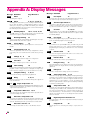
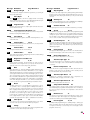
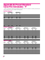
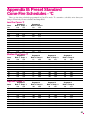
Download Sentry Sentry 2.0 Operating instructions

Transcript
Sentry 2.0
Digital Temperature Controller
Complete Operating Instructions
See pages 28-29 for instructions on upgrading your DTC
100, 600, 800 or 1000 series board to the Sentry.
Cone-Fire (pg 8-11)
From IdLE, press 1.
Delay (pg 6)
Available only on ceramic
kilns. Fires to a pyrometric
cone. Enter cone, speed,
pre-heat, hold, and slow cool.
From IdLE, press 3.
Enter time in hours:minutes.
Delays the start of firing.
Ramp-Hold (pg 12-15)
Add Time (pg 6)
Select stored program (1 - 4).
Enter rate, temperature, and
hold for each segment.
Each additional key press
adds five minutes to a hold.
It works in both Ramp-Hold
and Cone-Fire.
During firing, press 2.
From IdLE, press 4.
Alarm (pg 6)
Present Status (pg 6)
From IdLE or during
firing, press 7.
Press 5 during firing.
Enter a temperature. When
alarm sounds during firing,
press Enter.
Shows the segment that is
currently firing. Works in
both Ramp-Hold and
Cone-Fire.
Enter/Start (pg 7)
Program Review (pg 6)
From IdLE or during
firing, press 6.
Press Enter/Start after each
step in programming a firing.
Press Enter/Start once to begin the firing.
Options (pg 17 - 21)
Shows the program that is
loaded in memory and ready to
fire, or the one that is firing.
Id
Computer ID Select identi-
Stop/Back (pg 7)
From IdLE, press 0. Press fication number for output to a
Press during firing or
Enter for option displayed. computer.
Cone-Fire Options
TEdE Temperature Deviation programming.
SPd Speed Change the speed
of a Cone-Fire program beyond
the Fast, Medium, or Slow.
OFST Cone Offset Adjust controller to a witness cone.
FAN Vent Fan Selects when
the vent fan will operate. (Special
option not on all kilns.)
Standard Options
TCOS Thermocouple Offset
Calibrate the thermocouple
temperature.
CHG- Select °F or °C.
TC Thermocouple Type Select Type K, S or R.
AOP AOP Outlet Select vent
fan or alarm. This is a special option not on all kilns.
Set temperature sensitivity of error codes.
SFTY Maximum temp.
ELEC Electronics Temp.
Check board for overheating.
LOCK Program Lock Make a
program tamper-proof.
CFG Configuration Code
For technicians.
SOFT Software Version
For technicians.
TEST Element Test Diagnostics tool for checking elements.
RST Reset Removes cone
and thermocouple offsets, etc.
Stops a firing. In Options,
takes you back to IdLE.
During programming,
takes you back one step
each time key is pressed.
Cone Table & Skip
Segment (pg 7)
From IdLE or during
firing, press 9.
From IdLE, shows temperature for the cone you enter.
While Firing: In Ramp-Hold,
skips to the next ramp. In
Cone-Fire, skips out of
Pre-Heat or Hold.
Multiple Zone Options
DIFF Difference Largest
temperature difference between any two zones.
CAdJ Center Adjustment
Change center heat of some
two-zone kilns.
T123 Zone Temperatures Shows temperature of
each zone.
1
Introduction
Thank you for purchasing the Sentry micro processor, our most advanced generation of digital temperature controllers. The easiest way to learn to operate the Sentry is to sit down in
front of it with these instructions and play with it. Spend time understanding the controller
before you begin to use it.
Damage caused by failure to follow instructions is not covered by warranty.
The Sentry operates in Cone-Fire and Ramp-Hold similar to the earlier DTC 600, 800, and
1000 series. If you are familiar with the earlier controllers, you can follow many of the same
operating procedures with the Sentry.
The Cone-Fire mode applies to ceramics only. If you purchased a heat treating, glass fusing,
enameling or jewelry furnace, your version of the Sentry will include only the Ramp-Hold
mode, not the Cone-Fire. In this case, please disregard “FAST,” “MEDIUM,” “SLOW,”
“Cone Fire” and “Cone #s” on your keypad.
If you purchased the TnF 2 portable controller, you should find a TnF 2 installation
instruction sheet in addition to these instructions.
Instructions for multiple-zone kilns are included in this manual. If you are not sure whether
your kiln is multiple-zone, look into the firing chamber. If you see two or three thermocouple
tips, your kiln is multiple-zone. If you see only one thermocouple, skip multiple-zone
instructions.
Do not worry if you hear a distinct clicking noise during operation. Mechanical relays click as
they turn the heating elements on and off.
You can connect your Sentry controller to a personal computer, which will allow you to graph
your firings and to monitor them from a distance. Ask for the computer inteface kit, which
consists of a cable, a computer chip for the back of the Sentry, and software for your
computer.
Once you learn the basic features of the Sentry, you will be able to control every stage of firing.
This offers learning opportunities and convenience difficult to imagine with a manual controlled kiln.
©2001, by Paragon Industries, Inc. IM-204/5-01
2
Contents
Basic Pointers . . . . . . . . . . 4
Which Instructions
Apply to Your Controller . . . . . . . . . . 4
Room Temperature and Humidity. . . 4
Thunder Storms and Power Surges . 4
Display Lights . . . . . . . . . . . . . . . . . . 5
How to Get IdLE to Display . . . . . . . . 5
Firing Completion Message . . . . . . . 5
Repeat Firings . . . . . . . . . . . . . . . . . . 5
Thermocouple Inspection . . . . . . . . . 5
The “LId” Display . . . . . . . . . . . . . . . . 5
The Keys . . . . . . . . . . . . . . . 6
Correcting Entries . . . . . . . . . . . . . . . 6
1 / Cone Fire . . . . . . . . . . . . . . . . . . . 6
2 / Add Time . . . . . . . . . . . . . . . . . . . 6
3 / Delay. . . . . . . . . . . . . . . . . . . . . . . 6
4 / Ramp Hold . . . . . . . . . . . . . . . . . . 6
5 / Present Status . . . . . . . . . . . . . . . 6
6 / Program Review . . . . . . . . . . . . . . 6
7 / Alarm. . . . . . . . . . . . . . . . . . . . . . . 6
9 / Cone Numbers & Skip Segment . 7
Enter/Start . . . . . . . . . . . . . . . . . . . . . 7
The Options Key . . . . . . . . . . . . . . . . 7
The Stop/Back Key . . . . . . . . . . . . . . 7
Cone-Fire . . . . . . . . . . . . . . 8
Standard Schedules
Low Fire Cones 022 - 011. . . . . . . . 9
Middle Fire Cones 010 - 01 . . . . . . 9
High Fire Cones 1 - 10 . . . . . . . . . . 9
Speed (SPd) . . . . . . . . . . . . . . . . . . . 9
Pre-Heat (PRHT) . . . . . . . . . . . . . . . . 9
Hold (HOLd) . . . . . . . . . . . . . . . . . . 10
Cone-Fire Programming . . . . . . . . . 10
Slow Cooling (COOL) . . . . . . . . . . . 11
When the Kiln Shuts Off Too Soon . 11
For Kilns with AOP Outlet . . . . . . . . 11
Ramp-Hold . . . . . . . . . . . . 12
Definition of a Segment . . . . . . . . . . 12
Ramp-Hold Programming . . . . . . . . 13
User Programs (USER) . . . . . . . . . . 13
Firing a Stored User Program . . . . . 14
Rate . . . . . . . . . . . . . . . . . . . . . . . . . 14
Hold (HOLd) . . . . . . . . . . . . . . . . . . 14
AOP Fan. . . . . . . . . . . . . . . . . . . . . . 14
Segments for Controlled Cooling . . 14
Sample Firing Schedules . . . . . . . . 14
Cone-Fire Program Fired in
Ramp-Hold . . . . . . . . . . . . . . . . . . 14
Sculptured Stoneware Bisque
Firing Schedule, Cone 04. . . . . . . 14
Glass Fusing Firing Schedule . . . 15
Glass Slumping Firing Schedule . 15
Starting a Firing in a Hot Kiln. . . . . . 15
When the Kiln Shuts Off Too Soon . 15
Multiple Zone Kilns . . . . . 16
An Overview of Multiple
Zone Firing. . . . . . . . . . . . . . . . . . . . 16
Viewing Zone Temperatures . . . . . . 16
Two Zone Kilns: Adjust Heat in
Center Section (CAdJ). . . . . . . . . . . 16
Thermocouple Failure
In a Multiple Zone Kiln . . . . . . . . . . . 16
Power Output Lights . . . . . . . . . . . . 16
Testing Multiple Zone Elements . . . 16
Options: Cone-Fire. . . . . . 17
Cone-Fire Speed (Spd) . . . . . . . . . . 17
Cone Offset (OFST) . . . . . . . . . . . . . 17
Interpreting Cone Bending . . . . . . 18
When Cone Temperature
Is Off More Than 20°F/11°C . . . . . 18
Fan (FAN) . . . . . . . . . . . . . . . . . . . . 18
Options: General . . . . . . . 18
Thermocouple Offset (TCOS) . . . . . 18
Thermocouple Offset for
Ceramic Firings. . . . . . . . . . . . . . . 18
Calibrating Thermocouple Offset
With a Digital Pyrometer . . . . . . . . 19
Setting Thermocouple Offset . . . . 19
Multiple Zone
Thermocouple Offset . . . . . . . . . . 19
Selecting °F or °C (CHG-) . . . . . . . . 19
°F/°C Temperature
Conversion Formula . . . . . . . . . . . 19
Thermocouple Type (TC) . . . . . . . . 19
AOP Outlet (AOP) . . . . . . . . . . . . . . 20
Computer ID (ID) . . . . . . . . . . . . . . . 20
Temperature Deviation (TEDE) . . . . 20
Maximum Temperature (SFTY) . . . . 20
Electronics Temperture (ELEC). . . . 20
Program Lock (LOCK) . . . . . . . . . . . 20
Configuration Code (CFG) . . . . . . . 21
Software Version (SOFT). . . . . . . . . 21
Element Test (TEST) . . . . . . . . . . . . 21
Reset (RST) . . . . . . . . . . . . . . . . . . . 21
Error Messages . . . . . . . . 22
FTC / Failed to Cool. . . . . . . . . . . . . 22
FTH / Failed to Heat. . . . . . . . . . . . . 22
LTdE / Low Temperature
Deviation . . . . . . . . . . . . . . . . . . . . . 22
PF / Power Failure . . . . . . . . . . . . . . 22
BAdP / Bad Programming . . . . . . . . 22
ETH / Electronics Too Hot . . . . . . . . 22
FAIL / Thermocouple Failure . . . . . . 22
FTL / Firing Too Long . . . . . . . . . . . 22
HTdE / High Temperature
Deviation . . . . . . . . . . . . . . . . . . . . . 22
PF 2 / Power Failure . . . . . . . . . . . . 22
PF 3 / Power Failure . . . . . . . . . . . . 22
How the Sentry
Handles Power Failures. . . . . . . . . . 23
Using Ceramic Witness Cones
After an Extended Power Failure . 23
PLOG Error Codes. . . . . . . . . . . . . . 23
TCdE / Uneven Multiple
Zone Temperatures . . . . . . . . . . . . . 23
TCR / Thermocouple
Leads Reversed . . . . . . . . . . . . . . . . 23
Appendix A
Display Messages . . . . . . . . . . . . . . 24
Appendix B
Standard Cone-Fire Schedules . . . . 26
Appendix C
Upgrading the DTC 100, 600, 800 &
1000 to the Sentry . . . . . . . . . . . . . . 28
Appendix D
Orton Pyrometric Cone
Temperature Equivalents . . . . . . . . 30
Appendix E
Ramp-Hold Shorthand . . . . . . . . . . 31
Appendix F
Cone-Fire Shorthand . . . . . . . . . . . . 32
Options: Multiple Zone . . 21
Zone Temperature
Difference (DIFF) . . . . . . . . . . . . . . . 21
Two Zone Kilns: Adjust Heat in
Center Section (CAdJ). . . . . . . . . . . 21
Zone Temperatures (T123) . . . . . . . 21
3
Safety
The warranty on your Sentry controller does not cover
damage from overfiring, regardless of the circumstances. It
is the operator’s responsibility to make sure the kiln turns off
at the end of the firing. Follow these safety rules in addition
to the ones in your kiln or furnace manual.
When the kiln is not in
use, disconnect the power
and keep the lid or door
closed. (For larger kilns
with heavy cordsets, we
recommend a power disconnect box near the
kiln.)
Basic Pointers
Which Instructions
Apply to Your Controller
The Sentry fires in two modes:
I
Ceramic Cone-Fire, based on pyrometric cones.
I
Ramp-Hold, based on custom firing rates and target
temperatures.
Do not leave the kiln unattended, especially
near the expected shut-off time.
Ceramic kilns use both Cone-Fire and Ramp-Hold. Heat
treating, glass fusing, and enameling furnaces and kilns
come with Ramp-Hold only.
Wear firing safety glasses when looking into
peephole of a hot kiln.
1 From IdLE display, press 1. If CONE appears, you
have Cone-Fire mode. If the 1key does not respond,
you have Ramp-Hold mode only.
Do not touch hot sides of kiln or furnace. Keep
unsupervised children away.
Install your kiln or furnace at least 12 inches
from any wall or combustible surface. (See
manufacturer’s recommendation for your
model.)
Do not open lid or door until kiln or furnace has
cooled and all switches are off.
Fire only in a well-ventilated, covered and protected area away from flammable materials.
Keep cordset away from hot sides of kiln or furnace.
DANGEROUS VOLTAGE! Do not touch heating elements with anything. Disconnect kiln or
furnace before servicing.
Do not operate if the controller itself is hotter
than 150°F/66°C. (See instructions on page 20
for checking board temperature.) Never allow
the firing room temperature to exceed
110°F/43°C. (Measure room temperature three
feet from the kiln.)
Stop a firing by pressing the STOP button, not
by disconnecting the power. In certain conditions, the controller will interpret a power interruption as a power failure and turn the kiln back
on when you reconnect the power.
4
Chapter 1
2 Press STOP to bring the controller back to IdLE .
Note: FAST, MEDIUM, SLOW, CONE-FIRE,
and CONE #s printed on the controller faceplate
apply only to Cone-Fire mode.
If you have Ramp-Hold only, skip pages 8 - 11.
Room Temperature and Humidity
It is okay to store the Sentry at sub-zero temperatures.
But before operating, raise the room temperature to at least
32°F/0°C.
Note: The Sentry will register sub-zero °F/°C temperatures. However, 32°F/0°C is the lowest recommended operating temperature.
The circuit board is rated for 158°F/70°C maximum operating temperature. However, the maximum recommended temperature is 125°F/52°C. Open windows and exhaust hot air from the room to lower temperature. (See page
20 to check circuit board temperature.)
High humidity will not adversely affect the Sentry unless
water condenses on the circuit board. In this case, do not fire
the kiln until the moisture has evaporated from the board.
Thunder Storms and Power Surges
Unplug the kiln when not in use, especially during thunder storms and in areas with frequent power surges. If the
kiln is part way through a firing when a storm begins, it may
be okay to continue the firing. When the kiln shuts off, disconnect the power.
CAUTION: when firing the kiln during a storm, do
not leave the kiln unattended!
Display Lights
Firing Completion Message
When the firing has completed, four messages will cycle
one after the other:
1 CPLT (complete)
2 Firing time in hours and minutes (amount shown
does not include Cone-Fire slow cooling time)
Single Center Light: Time
A lower center dot appears during time display. It separates hours from minutes (i.e. 1 hour, 30 minutes displays as
01.30). During temperature display, the dot disappears.
3 The temperature the kiln fired to in Cone-Fire, or
the temperature of the last segment in Ramp-Hold
4 The current kiln temperature
Note: If the alarm (see page 6) sounded, and then
the kiln fired to completion, you will see ALAR instead of CPLT . Press ENTER. CPLT will appear.
Repeat Firings
Power Output Lights
The Sentry turns on the heating elements intermittently
through relays. The power output lights in the right side of
the display appear when the Sentry sends power to the relay(s).
I
Single Zone Kiln When the Sentry sends power to the
relays, all three lights appear.
I
Two Zone Kiln The top light shows power to the relay
for the top section of the kiln. The bottom light shows
power to the bottom. Ignore the center light.
I
Three Zone Kiln The top light indicates power to the
top section relay, the middle light to the middle section,
and the bottom light to the bottom.
°F
°C
Single Right-Hand Light: °C
When temperature is displayed in °C, a light appears in
the lower right. In °F it disappears.
How to Get IdLE to Display
The controller displays IdLE when you first apply power
to the kiln. Operations begin from IdLE . You can’t fire the
kiln until IdLE appears.
I
If you press STOP during a firing, AbRT will appear. To
get back to IdLE , press ENTER.
I
If the display shows an error message such as FAIL instead of IdLE , see pages 22 - 23.
I
CPLT (firing completed) appears at the end of a firing.
To make IdLE appear, press any key.
To repeat the last firing, press ENTER from IdLE . The
kiln will begin firing. This works in both Cone-Fire and
Ramp-Hold. But first, make sure you are repeating the correct firing by using “Program Review” (see page 6). For repeat firings that you don’t want to inadvertently change, see
“Program Lock,” page 20.
Thermocouple Inspection
The small rod protruding into the firing chamber is the
temperature sensor, or thermocouple.
CAUTION: Bumping the thermocouple can push
it out of the firing chamber. This could cause an
overfire! The controller does not contain an alarm
to detect this type of failure.
Thermocouples come in different widths. The wider the
thermocouple, the farther it should extend into the firing
chamber. A ¼” diameter thermocouple should extend into
the firing chamber about 1”. A 1/8” thermocouple should extend into the chamber ½” - 5/8”.
Keep shelves, posts and ware 1” - 1 ½” away from the
thermocouple. Keep an extra thermocouple on hand, especially if you fire hotter than 2000°F/1093°C.
If you are using a portable, separate controller, you will
need to install the thermocouple onto the kiln. See the separate TnF 2 installation instructions.
The “LId” Display
Reasons LId appears in the display:
I
The kiln is equipped with the optional safety switch.
(The switch turns off power to the elements when the lid
or door is open.) LId appears in the display while the lid
is open during firing.
I
On the back of the Sentry circuit board, at the top right
side, is a small two-pin terminal. If the connector on that
terminal is missing, LId will appear in the display during firing. The elements will not turn on. (If the two-pin
connector is missing, you can buy another from a computer supply store.)
I
The safety lid switch is defective or the safety switch wire
is broken.
5
automatic. The operator assumes full responsibility
for shutting the kiln off at the proper time.
Chapter 2
The Keys
Correcting Entries
If you enter the wrong temperature, cone, time, etc., while
programming, enter 0000. Then enter the correct numbers
before pressing ENTER. See also the Stop/Back Key, page 7.
4 / Ramp Hold
Ramp-Hold fires the kiln to the temperature you specify, whereas Cone-Fire fires to
a pyrometric cone. Press 4 from IdLE to
program a firing or to select a stored program. See
“Ramp-Hold,” page 12.
5 / Present Status
1 / Cone Fire
Cone-Fire is a method of firing ceramics
to a pyrometric cone. See Chapter 3, page 8,
for details. To find out if your Sentry includes Cone-Fire:
1 From IdLE display, press 1. If CONE appears, you
have Cone-Fire mode. If the 1 key does not respond, you have Ramp-Hold mode only.
Press 5 during a firing to display the current segment that is firing. The messages
that can appear in Present Status:
I
RA 1 Ramp (see page 12), and segment number.
I
Hd 1 Hold (see page 12), and segment number.
I
PRHT Cone-Fire Pre-Heat (see page 9).
I
COOL Cone-Fire Slow Cooling (see page 11).
2 Press STOP to bring the controller back to IdLE .
2 / Add Time
This key adds five minutes to a Hold. It is
designed for ceramists who watch witness
cones through the peephole, and for glass
artists who inspect the glass near the end of firing.
1 During a firing, press Add Time. HOLd , and time
in hold, will appear.
2 Press Add Time again. The time shown will increase by 5 minutes. In a few seconds, temperature
display will return.
Note: Add Time will add 5 minutes to Hold in either Cone-Fire or Ramp-Hold, even if no hold had
been programmed. After hold time displays, 5 minutes are added with each press of the key.
Uses for Present Status:
I
You are firing a program that contains several heating
and cooling segments. Without Present Status, it would
be easy to lose track of which segment is firing.
I
In Cone-Fire, you may think the kiln has fired too long
when it is actually only in a slow cooling.
6 / Program Review
When you press ENTER to begin firing,
the controller will fire the program that is in
active memory. Program Review shows the
values for that program. The program in active memory is—
I
The program that was fired last, or
I
The program that was selected since the last firing.
Start Program Review from IdLE , or while firing, by
pressing 6.
3 / Delay
Note: In Program Review, Cone-Fire Fast speed
displays as F 20 . Slow speed displays as S 20 .
(These speeds are 20% faster and slower than the
standard speed.)
This delays the start of the firing by the
amount of time entered. Use it to fit a firing
into your schedule or to take advantage of
lower electric rates at night. Delay zeroes out after each firing. Therefore, it must be programmed for each firing.
7 / Alarm
The alarm sounds when the kiln reaches
the alarm temperature you enter. Use the
alarm to alert you to—
1 A Cone-Fire or Ramp-Hold program must be in active memory, ready to fire. (See pages 10 and 13.)
2 From IdLE press 3. Enter delay time (i.e., 5 ½
hours = 05.30). Press ENTER.
I
Lower the lid from venting position (ceramics).
3 To begin Delay, press ENTER once from IdLE . A
Delay count-down timer will appear.
I
Check the witness cone near shut-off time (ceramics).
I
Check the fusing or slumping of glass.
I
Remove the knife blade from the furnace at the end of
heat treating.
Note: Press START during delay to end the delay
and begin the firing. The maximum delay is 99
hours and 59 minutes.
CAUTION: For safety, do not leave the kiln alone
during a delay or a firing. We cannot guarantee your
kiln against overfiring even though the controller is
6
You can enter only one alarm temperature at a time. However, after the alarm beeps, you can set the alarm for another
temperature, as many times as you want, during the firing.
You can enter a higher or lower temperature than the current temperature. Entering an alarm temperature automatically erases the previous alarm temperature.
Setting Alarm From Idle
1 From IdLE , press 7. ALAR will appear alternating
with the last alarm temperature entered.
2 Enter alarm temperature. Press ENTER. IdLE will
appear. (Enter 0000 to turn alarm off.)
Note: 9999, as an alarm temperature, automatically changes to the maximum temperature rating
of your controller.
When the alarm sounds, shut it off by pressing any key except STOP. (The STOP key does not work while an alarm
sounds.) If the alarm sounds as soon as firing begins, it is because the alarm was set to a temperature below the current
temperature.
Setting Alarm During Firing
I
Skip Segment in Ramp-Hold
In Ramp-Hold, the firing will skip to the ramp of the next
segment from either a ramp or hold of the current segment.
(See page 12 for details on ramps, holds, and segments.)
Skip Segment Examples
For additional examples, see Chapter 4, pages 14 - 15.
Cone-Fire
In Cone-Fire you are firing to an 05 witness cone for the
first time. You select cone 04 with a 60 minute hold and a
slow cooling. After 30 minutes in hold, the 05 witness
cone bends to maturity. Use Skip Segment to end the
hold and begin Slow Cooling.
I
1 The alarm beeps while the kiln is firing. Press 7.
Note: Once you know how much hold time will
bend the witness cone, program that much hold for
the next firing.
2 Enter the new temperature.
3 Press ENTER. The kiln will continue firing.
If you touch 7, enter a new temperature, and forget to
press ENTER, the controller will merely continue firing.
Note: When an alarm sounds, firing to completion
does not shut the alarm off.
9 / Cone Numbers
& Skip Segment
Ramp-Hold
Skipping to a Cooling Segment: You have programmed
2167°F for a cone 5 glaze firing, followed by a segment for
controlled cooling. Watching the witness cone through
the peephole, you notice that cone 5 is bending at 2150°F.
Use Skip Segment to end the firing segment and begin
the one for slow cooling.
I
Note: Make a note of the temperature at which the
cone bent. Program that temperature for the next
firing.
Cone Table
Look up a cone temperature with the 9 key.
1 From IdLE , press 9. CONE will appear, then the
cone, if any, currently programmed in Cone-Fire.
2 Enter a pyrometric cone number. Press ENTER. The
display will show the cone temperature. If you enter a
non-existent cone number, the display will show
CONE , ready for you to enter a different cone number.
Note: Do not be concerned if the actual cone
shut-off temperature does not match the Cone Table. The temperature of a cone varies with firing
speed. The cone temperatures in Cone Table are
for self-supporting cones fired at a rate of 108°F /
60°C per hour during the last hour of firing.
To skip out of Cone-Fire Hold. Slow Cooling will begin.
(If the firing does not include Slow Cooling, Skip Segment will not end a Hold. Press STOPto end the firing.)
I
Skipping to a Hold: Skip Segment does not skip from a
ramp to a hold. It skips to the next segment. If you need to
skip to a hold, program an additional segment with the
hold that you want. Then skip to that segment. Example:
Segment 1: rate 500°F to 1828
Segment 2: rate 200°F to 1750 with 30 minute hold
Enter/Start
I
Press ENTERafter each step in programming a firing.
I
Press ENTER once to begin firing.
The Options Key
See Chapter 6, page 17.
Skip Segment
Skip Segment works only during firing. It jumps from the
current segment to the next one.
To skip a segment, press 9. SKIP will appear, then the
current segment. Press ENTER. (If you change your mind
and don’t want to skip that segment, don’t press ENTERafter
SKIP appears. Instead, press 9 again. The firing will continue in the same segment.)
Skip Segment in Cone-Fire
In Cone-Fire, Skip Segment works in Pre-Heat and Hold:
I
To skip out of Pre-Heat and begin the cone firing.
The Stop/Back Key
You can stop a firing at any time (except
when the alarm sounds) by pressing STOP.
If you inadvertently enter Ramp-Hold,
Cone-Fire, or Options, you do not have to go through all the
prompts to get back out. Press STOP to go to IdLE .
The STOP/BACK key is also like the Back button on an
Internet browser. It works in Cone-Fire and Ramp-Hold
programming. It will take you back one step every time you
press the key.
7
Chapter 3
Cone-Fire
Cone-Fire mode is based on
pyrometric cones. It is not designed for
heat treating, glass fusing and enameling.
For these firings, see “Ramp-Hold,”
page 12. Use Ramp-Hold to fire ceramic
pieces that require a custom firing
schedule, such as some types of stoneware sculpture or crystalline glaze.
Pyrometric Witness Cones
The Sentry shuts off automatically without cones. Nevertheless, every ceramic firing should include at least one witness cone (also called the shelf cone). The witness cone is
the most accurate measurement of heat work in a ceramic
firing.
If you fire the same size load and type of ware regularly,
the witness cones let you compare one firing to the next and
alert you when something is wrong. For example, if the witness cone bends less and less with each consecutive firing,
this may indicate thermocouple temperature drift.
Note: If the bending of the witness cone does not
match the Cone-Fire shut-off, you may want to adjust Cone Offset or Thermocouple Offset. See
pages 17 - 19. If the witness cones bend inconsistently from one firing to another, see “Sentry Troubleshooter,” a separate publication.
How to Position Cones on the Shelf
Position the witness cones
so that you can see them
through a peephole during firing. If the kiln takes longer than
usual to fire, you may wonder if
something has gone wrong and
the kiln is overfiring. But by
seeing the cones, you will know
how the firing is progressing. Use self-supporting
If you follow these guidelines, you should be able to see
the cones even at cone 10:
witness
cones on the shelf. They stand
upright without cone holders.
I
Place the cones 8” - 12” away from a peephole. Positioning them closer makes them difficult to see.
I
Have enough space around the cones to keep them from
touching a piece of ware when they bend.
I
Position cones so that when viewed from the peephole,
they are silhouetted by an element on the opposite kiln
wall. (Keep cones at least 2” from an element.)
8
I
The element that silhouettes the cones should be level
with the lower part of the cone. If the element is in line
with the upper part of the cone, you won’t be able to see
the cone when it bends.
I
If you use the three
cone system, always
have the higher temperature cone on the
same side in every firing. Otherwise you can
lose track of which cone
is which.
I
W e ar f ir in g saf e t y
glasses when viewing
the cones through the
peephole.
Silhouette the lower part of the cone
against an element. Keep the cone 8”
- 12” away from the peephole.
See your dealer if in
doubt about which cone number to use with each clay and
glaze.
Firing Schedules
Cone-Fire uses three firing schedules:
I
Low fire cones 022 - 011
I
Medium fire cones 010 - 01
I
High fire cones 1 - 10
Should you ever want to customize a Cone-Fire program,
transfer the firing schedule to Ramp-Hold. See Appendix B,
pages 26 - 27.
During a cone firing, press 5 (Present Status) to see
which stage, or segment, of the firing the kiln has reached.
The number displayed will be a segment number from one
of these firing schedules.
Note: Pre-Heat shows in Present Status as PRHT .
It is not given a separate segment number.
Firing time in each segment is approximate and depends
on the age of elements, voltage, size of load, and the firing
speed you have chosen.
CAUTION: Cone numbers beginning with 0 are
lower in temperature than those without the 0.
When programing a Cone-Fire, be sure you know
the difference between an 05 and 5. See “Temperature Equivalents Chart for Orton Self-Supporting
Pyrometric Cones,” Appendix D, page 30.
High Fire Cones 1 - 10 Firing Schedule
Low Fire Cones 022 - 011
This range includes decals, over-decorations, lusters,
and golds. The firing can be fast. Good venting is important,
because oils and other organics burn off. Do not close the lid
from the vented position until all odor has disappeared.
Low Fire Cones 022 - 011 Firing Schedule
Segment
Rate Per Hour
Time in Segment
1
396°F/220°C
2 hours
2
108°F/60°C
1 hour
Firing time is about 3 to 5 hours, depending on the cone and speed.
Middle Fire Cones 010 - 01
Use this range for earthenware and commercial low-fire
glazes. Glazes fired on bisque ware (ware that has already
been fired) can be fired faster than the unfired greenware. In
this cone range, slow firings can produce poor quality glazes.
In the following schedule, the firing is slowed during the
silica phase change (1063°F/573°C).
Earthenware and clays that contain ball clays, talc, and kaolin will burn off water, carbon, and sulfur. This reduces
weight by 10%.
Cooling too fast can produce glaze pinholes, blisters, and
craters. Unless cooling is slowed near 1063°F/573°C, a physical change in the silica can cause the ware to crack. For this
reason we recommend that you use Cone-Fire’s Slow
Cooling option (see page 11).
We recommend a 10 - 20 minute hold when firing
lead-free glazes.
Middle Fire Cones 010 - 01 Firing Schedule
Segment
Rate Per Hour
1
324°F/180°C
2 hours, 30 minutes
Time in Segment
2
153°F/85°C
35 minutes
3
180°F/100°C
2 hours, 40 minutes
4
108°F/60°C
1 hour, 30 minutes
Firing time is about 6 to 8 hours, depending on the cone and speed.
High Fire Cones 1 - 10
This is the firing range for porcelain and stoneware.
These bodies fire nearly to vitrification and can shrink up to
16%. Water, carbon and sulfur burn out during the early
stages and must be vented. The amount of oxygen in the kiln
affects the color of the fired clay. The high fire schedule below slows down during the last 210°F/100°C to produce
better density in the ware.
Typical porcelain clays are formulated from kaolin, feldspars, silica and ball clays. Weight loss is 10 - 12% and
shrinkage is as high as 20%. If overfired, porcelain may warp
or blister. Cone-fire’s Hold option usually enhances porcelain.
Segment
Rate Per Hour
1
324°F/180°C
2 hours, 30 minutes
Time in Segment
2
153°F/85°C
35 minutes
3
162°F/90°C
4 hours, 35 minutes
4
108°F/60°C
2 hours
Firing time is about 9 hours, 30 minutes to 11 hours, depending on the cone and
speed.
Cone-Fire Features
Speed (SPd)
The Cone-Fire schedules shown on this page are standard. When you select Medium speed in a Cone-Fire program, the kiln uses these standard firing schedules. When
you select Fast (1), the standard schedule fires 20% faster.
On Slow (3), it fires 20% slower.
You can also alter the firing speed even more under Speed
(Spd) in Options. See page 17.
Pre-Heat (PRHT)
Moist greenware can explode during firing. This happens
when the moisture in the clay turns to steam rapidly and cannot escape fast enough. The Sentry Pre-Heat feature dries
the ware at low temperature before the moisture can turn to
steam.
Pre-Heat is sometimes necessary when firing thick
greenware, such as stoneware. It may also be necessary in
humid weather, which inhibits drying. If possible, however,
avoid using Pre-Heat to dry greenware. If the greenware
feels damp or cool when you touch it to your cheek, dry it longer before firing. Use a dehumidifier in humid weather.
Drying greenware in the kiln tends to rust the kiln.
Note: During Pre-Heat, vent the lid. Otherwise the
firebricks will absorb moisture, leading to rust behind the steel case. Moisture in the firebrick can
also slow the firing to a crawl.
CAUTION: Venting the lid during Pre-Heat is so
important that some ceramists use the extended
vent position or even leave the lid open. If you do
this, you must be near your kiln at the end of
Pre-Heat to lower the lid.
Pre-Heat raises the temperature 60°F/33°C per hour to
200°F/93°C. Then it holds at 200°F/93°C for the time you
specify. Pre-Heat works in Cone-Fire only. After Pre-Heat is
finished, the kiln will automatically begin firing to the cone
you have selected.
Note: At high altitude, water boils at a lower temperature. This may cause moisture in the ware to
turn to steam even during Pre-Heat.
9
Cone-Fire Programming
Use these instructions for your first firings. Later
you may prefer “Cone-Fire Shorthand Programming,” page 32.
As the Sentry prompts for cone, speed, pre-heat,
hold, and slow cooling, values entered for the last firing
will appear. To use these values again, press ENTER.
To fire without Delay or Alarm: Follow steps 1
through 7 below. Then from IdLE press START. To
use Delay or Alarm, see also page 6.
1 Apply power to the kiln. 8888 then IdLE
will appear. (Press ENTER if IdLE does not
appear.)
2 Press 1. CONE will appear. Enter cone number. (If the 1 key does not respond, your controller uses Ramp-Hold only.)
3 Press ENTER. SPd will appear. Enter speed:
FAST (1), MEDIUM (2), SLOW (3). (Medium speed will display as Std .)
4 Press ENTER. PRHT will appear. To use
Pre-Heat, enter time. Otherwise enter 0.
5 Press ENTER. HOLd will appear. To soak the
ware at the end of firing, enter a hold time.
Otherwise enter 0.
6 Press ENTER. COOL will appear. To use
Slow Cooling, enter cooling rate as degrees
per hour. (180°F/82°C is maximum rate.
Press 0 to turn Slow Cooling off.)
7 Press ENTER. IdLE will appear.
8 To set Alarm: Press 7. ALAR will appear. Enter alarm temperature. (Press 0 to turn alarm
off.) Then press ENTER.
9 To set Delay: Press 3. dELA will appear. Enter delay time. Press ENTER. (Delay zeroes
out after each firing.)
10 To start program, press ENTER once.
STRT will appear, then temperature. If
Delay was programmed, DELA will appear,
then time remaining until start. To stop the
program during firing, press STOP.
When program fires to completion, CPLT will appear. Press ENTER. IdLE will appear. To shut off the
alarm when it sounds during a firing, press ENTER.
Mirror Test
This test will help you determine how much Pre-Heat
to use. Occasionally during
Pre-Heat, hold a mirror near
the top peephole. (Be careful
to avoid burns.) The mirror
must be at room temperature, not hot, so hold it near
the peephole for only several
seconds.
Vent the kiln until moisture no longer fogs a mirror.
If the mirror fogs, moisture is still escaping from the
ware. When the mirror no longer fogs, you can exit Pre-Heat
and begin the firing.
To interrupt Pre-Heat and begin firing to the cone in
Cone-Fire, press 9 (Skip Segment). SKIP , alternating with
1 , will appear. Press ENTER. Segment 1 of the firing will
now begin. (See Cone-Fire firing schedules, page 9.)
Note: If you are using a vent fan, such as the Orton
KilnVent, turn the fan on during Pre-Heat. The fan
will help to remove moisture. (AOP Fan users: see
the Fan option, page 18.)
How to Use Pre-Heat When Kiln is Above
200°F/93°C at Beginning of Firing
If you begin firing with Pre-Heat in a kiln that is already
hotter than Pre-Heat temperature, the kiln will skip
Pre-Heat and begin firing to the cone. There are two ways to
use Pre-Heat in this situation:
I
Wait until the kiln cools below 200°F before starting the
firing. This is the preferred method.
I
Load the kiln and start the firing, but include enough
time in Delay for the kiln to cool below 200°F before
Pre-Heat begins.
Hold (HOLd)
Cone-Fire Hold heat-soaks the ware at the cone temperature at the end of the firing. Without Hold, the kiln shuts off
after it reaches the cone temperature. Hold maintains the
cone temperature for the period you specify. Hold helps even
out the temperature throughout the kiln. It also helps the
heat to penetrate completely into the clay. (Rapid firing is
like cooking: the turkey will be done on the outside but not
on the inside.) Hold helps glaze absorb china paint. It helps
to heal glaze defects such as bubbles. A little hold time can
yield dramatic results.
CAUTION: Too much hold time can overfire your
ware and burn out colors.
One way to add Hold time without over-firing is to fire to
one cone cooler than needed. Then add enough hold time to
bend the next hotter cone. Hold time needed to bend the
next cone will vary. As a rule of thumb, 45 - 60 minutes of
hold = one cone of heat work.
Example: to fire to cone 05, program Cone-Fire for 06
and add 45-60 minutes of hold time.
10
Watch the pyrometric witness cones through the peephole. Press STOPwhen the correct witness cone bends, noting how much Hold time was needed. Program that much
Hold time the next time you fire the same type of ware loaded
to the same capacity.
Note: During Hold, the display temperature will
alternate with time left in Hold. To figure hold time
for the next firing, subtract time left in Hold from
the total Hold time entered.
When Hold is set to 99.99 hours, the Sentry will remain at
that temperature indefinitely, until STOP is pressed.
Slow Cooling (COOL)
Slow cooling enhances the quality of some ceramic
glazes. Slow cooling encourages crystal develoment, deeper
gloss, and sometimes startling color shifts. Iron red glazes
seem to respond well to slow cooling. For these reasons we
have added a Slow Cooling feature to Cone-Fire.
I
Slow Cooling begins after the cone firing (and Hold, if
any) and ends at 392°F/200°C.
I
When COOL appears in Cone-Fire programming, enter
a cooling rate between 1°F/C to 180°F/82°C. A good starting point is a rate of 90°F/50°C.
I
Enter a rate of 0 to turn Slow Cooling off.
Note: Slow Cooling can extend the firing time by
many hours. For instance, if the shutoff temperature is 1945°F/1063°C, and the cooling rate is
100°F/55°C, the kiln will take 15 ½ hours to reach
392°F/200°C.
Note: By looking at the witness cones through a
peephole, you will know if the kiln shuts off too
soon.
If the kiln shuts off within 100°F/55°C of maturity, and the
temperature drops 50°F/28°C or more after the kiln shuts
off, do not depend on the witness cones. Once they cool
50°F/28°C after they have been heated to within 100°F/55°C
of maturity, they will not bend properly. This is because they
form a hard shell.
Wrong Thermocouple Type
If a Type-K thermocouple is installed on your kiln, but
your controller is set for Type-S, the kiln will continually
underfire by a wide margin. See page 19 to check thermocouple type.
For Kilns with AOP Outlet
The AOP (auxiliary output) is a special-order receptacle
mounted in the kiln switch box. The Sentry controls power
to the AOP receptacle. The AOP is usually used to power a
kiln vent.
The Fan option, which is accessed through the OPTIONS
key, determines when an AOP-powered kiln vent will operate during Cone-Fire.
Before the Fan option will appear on the Options list, (1)
you must enter a Cone-Fire program in active memory and
(2) you must select FAN3 in the AOP option. (See page 20
for instructions on selecting FAN3 in the AOP option.)
1 From IdLE , press OPTIONS repeatedly until FAN
appears.
2 Press ENTER. Use the 1 and 2 keys to select one of
these settings:
When the Kiln Shuts Off Too Soon
If the kiln shuts off before the pyrometric witness cone
bends, you can turn the kiln back on and keep firing. Simply
program the next hotter cone in Cone-Fire. Then from
IdLE , press START. The kiln will begin firing, taking up
where it left off.
I
ON
The vent is on during Pre-Heat, the cone firing,
and Slow Cooling. It turns off at 212°F/100°C.
I
OPT
The vent is on during Pre-Heat and the cone firing. It is off during Slow Cooling.
I
OFF
The vent is off all the time.
3 After selecting one of the above, press ENTER. Press
STOP to return to IdLE .
11
Chapter 4
Ramp-Hold
Definition of a Segment
Ramp-Hold fires in segments. Every segment must have
a target temperature and a heating rate to reach that temperature. Shown in diagram A is a segment with a temperature
of 750°.
Diagram C: a single segment with hold. The two parts of a segment are
the ramp and the hold. Not all segments have a hold, but they all have a
ramp.
A segment, which is a target temperature and a rate of
heating to reach that temperature, can also have a hold. Hold
maintains the target temperature for the length of time you
specify. (Diagram C, above.)
A segment has two parts:
Diagram A: a single segment.
Rate is figured in degrees per hour. In Diagram A above,
the temperature takes two hours to reach 750°. The rate is
750 ÷2 = 375.
Diagram B, below, shows three rates. A rate of 1000° will
reach 1000° in 1 hour. A rate of 500° will reach 1000° in 2
hours. A rate of 333° will reach 1000° in 3 hours.
I
Ramp: where the temperature changes
I
Hold: where the temperature remains the same
A segment can have only one ramp and only one hold.
Therefore, if you need more than one hold, you will have to
add additional segments to the firing. Firing to a temperature at a single rate would need only one segment. Reasons to
add more segments:
I
To change the heating rate
I
To add a hold somewhere below the shut-off temperature
I
To change the temperature direction. Example: to control the cooling rate.
Diagram D, below, shows a 3 segment firing. Two segments were used on the way up in temperature. Another
segment was added for controlled cooling.
Diagram B: Rate is degrees per hour. This diagram shows 3 rates. Divide the target temperature by the number of hours it took to reach that
temperature.
Diagram D: a 3 segment firing. Only 2 segments have a hold.
12
Ramp-Hold Programming
Use these instructions for your first firings.
Later you may prefer “Ramp-Hold Shorthand Instructions,” page 31.
As the program prompts for segments, rate,
temperature, etc., you will see values from the last
firing. To use these again, press ENTER. To control
cooling, set the segment to a lower temperature
than that of the preceding segment.
To fire without Alarm or Delay: Follow steps
1 through 7. Then press START once.
1 Apply power to the kiln. 8888 then IdLE
will appear. (Press ENTERif IdLE does not
appear.)
2 Press 4. USER will appear. Enter a number
from 1 to 4.
3 Press ENTER. rA 1 will appear. Enter firing
rate for segment 1 (temperature change per
hour: from 1° to 9999°).
4 Press ENTER. °F 1 (or °C 1) will appear.
Enter the target temperature of segment 1.
5 Press ENTER. Hd 1 will appear. Enter segment 1 hold time in hours/minutes (e.g. 12
hours, 30 minutes = 12.30). No hold = 0.
6 Press ENTER. If FN 1 appears, and you have
an AOP receptacle on your kiln, select ON or
OFF. Press ENTER. (For more details on
AOP, see AOP option, page 20.)
User Programs (USER)
When you enter Ramp-Hold mode, the first prompt to appear is USER , meaning, “Select one of your programs.”
You, the user, can make your own firing schedules and store
them in memory. A firing schedule, or program, is the segments needed for a firing. To make a segment, you will need
three facts:
I
rate (how fast temperature changes in degrees per hour)
I
target temperature
I
hold, if any
The controller can retain four user programs in memory
even when power is turned off. User programs are numbered from 1 through 4. User program #1 can have up to 20
segments. User programs #2 - #4 can have ten segments
each. You don’t have to use all 20 or all 10 segments—only
the number needed per firing. Often one segment is all you
will need. A User program can be as simple as a single ramp.
When using Ramp-Hold for the first time, press 1 when
USER appears. Your first firing will be stored as User Pro-
gram #1.
Each time you store another program, select another
available number, such as 2, at the USER prompt. Adding a
program to a user number over-writes any existing program
stored there. Write down your User Programs.
Note: If you don’t need all the segments available
in a User program, zero out the unused segments.
First, enter values for the segments needed. At the
7 Continue entering values for the segments
needed. When RA _ appears for the first
segment you don’t need, press 0, then
ENTER. IdLE will appear.
8 To set Alarm: press 7. ALAR will appear.
Enter alarm temperature. (Enter 0 to turn
alarm off.) Then press ENTER. IdLE will
appear.
9 To set Delay: press 3. dELA will appear.
Enter delay time (i.e. 12 hours, 30 minutes
= 12.30). Then press ENTER. (Delay zeroes
out after each completed firing.) IdLE will
appear.
10 To start program, press ENTER once.
STRT will appear, then kiln temperature. If
a delay was programmed, STRT will appear, then time remaining until start. To
stop the firing, press STOP.
Write down each program stored in memory.
Before firing, use Program Review to be sure
everything is correct.
RA _ prompt for the segment you don’t need, press
0, then ENTER. The display will return to IdLE .
Note: For repeat firings that you don’t want to inadvertently change, see Program Lock, page 20.
We recommend using Program Review (page 6)
before firing. When program fires to completion,
CPLT will appear. Press ENTER. IdLE will appear. To shut off the alarm when it sounds during a
firing, press ENTER.
13
Firing a Stored User Program
To use a stored program, press 4 from IdLE. Enter the
program number at the USER prompt. Press ENTER. If
there are no changes to the program, press STOP. IdLE will
appear. The controller is ready to fire your selected program.
To begin firing, press ENTER once. (Use “Program Review,” page 6, before firing. See also “Repeat Firings,” page
5.)
Rate
As stated before, each segment must include a rate, programmed as degrees of temperature change per hour.
The kiln will fire at full power when the rate is
1799°F/999°C or higher. Programming a rate of 9999 is the
easiest way to program a maximum rate.
Note:
In Program Review, 9999 is displayed as
FULL . When a kiln is heated at full power, it may
over-shoot the target temperature, especially in the
lower range. To avoid this, add an extra segment
with a slower rate for the last 20 degrees of temperature rise.
CAUTION: The Sentry includes error messages
to warn you when the kiln is at the wrong temperature. Firing the kiln at full rate turns off some of
these warnings. For details, see “Temperature Deviation,” page 20.
If you are not sure how fast to fire, remember an old firing
adage: “When in doubt, slow it down.”
Hold (HOLd)
Hold maintains the temperature of a segment for the time
you specify. Hold gives the temperature time to become
more even throughout the kiln. Hold can be used in either
heating up or cooling down segments.
Ceramics: Wearing firing safety glasses, watch the witness cone near the end of the firing. (See page 8.) When the
witness cone bends, note the hold time. The next time you
fire the same type of ware loaded to the same capacity, program that amount of hold time.
Note: During Hold, the display temperature will
alternate with time left in Hold. To figure hold time
needed for the next firing, subtract time left in Hold
from total Hold time entered.
When Hold is set to 99.99 hours, the Sentry will remain at
that temperature indefinitely, until STOP is pressed.
AOP Fan
The optional AOP (auxiliary output) is a special-order
electrical receptacle mounted in the kiln’s switch box. This
receptacle can power a kiln vent or external alarm. (See Options, page 20.) In Ramp-Hold, the prompt for the AOP outlet is FN , which can be turned on or off for each segment.
Segments for Controlled Cooling
For controlled cooling, program a segment to a lower
temperature than that of the preceding segment.
If you prop the lid for a fast cooling, program a fast cooling
rate. If you program a slow cooling rate, but lower the temperature quickly by propping the lid, the controller will defeat your fast cooling. It will raise the temperature again.
Glass fusers sometimes flash-cool the glass at the end of
fusing. They lift the lid slightly to remove heat, then close it
again. This takes the glass down rapidly through the
devitrification range. To program a flash-cool, use a rate of
9999.
Suppose you enter a cooling rate that is faster than the
kiln is able to cool? Depending on the rate you enter, you may
get an alarm message. (Press ENTER to turn off the alarm.)
The controller, of course, cannot speed cooling
beyond the kiln’s natural cooling rate.
Note: During fast cooling, do not open the lid /door
all the way. Do not force-cool the kiln with a fan.
Sample Firing Schedules
These sample firing schedules illustrate different ways to
use your Sentry. When designing a firing schedule for materials you are unfamiliar with, or when using one of these
schedules, test-fire samples first.
Cone-Fire Program Fired in Ramp-Hold
The following firing schedule is the cone 04 Cone-Fire
schedule at standard (medium) speed. (See pages 26 - 27.) A
slow-cooling segment was added.
Rate
°F/°C
Temp.
°F/°C
Hold
1
324/180
1022/550
00.00
2
153/85
1112/600
00.00
3
180/100
1837/1003
00.00
4
108/60
1945/1063
00.00
5
150/83
1000/537
00.00
Segment
In this schedule, the kiln will cool at 150°F/83°C per hour
to 1000°F/537°C. Some ceramists use slow cooling with certain glazes.
Sculptured Stoneware Bisque
Firing Schedule, Cone 04
Rate
Segment
Temp.
°F/°C
°F/°C
Hold
1
60/33
200/93
03.00
2
80/44
700/371
02.00
3
80/44
1100/593
00.00
4
108/60
1945/1062
00.00
5
150/83
1400/760
00.00
This slow firing is for thick stoneware. Change the target
temperature in segment 4 when firing to a different pyrometric cone. The ware should be bone dry. Test samples until you are sure the schedule works for your clay.
14
If you are not using a kiln vent, leave peephole plugs out
and vent the lid. Set the alarm to 1000°F. When the alarm
sounds, close the lid from venting position.
Set the alarm again, this time to 1850° F. When it sounds,
check the witness cone through the peephole. When the
cone bends to six o’clock, write down the temperature. (Use
that temperature in segment 4 on your next firing of the
same type of ware.) Then press 9, ENTER(Skip Segment).
This will advance you to segment 5, a slow cooling segment. Do not open the lid until the kiln has cooled to room
temperature.
Glass Fusing Firing Schedule
Rate
°F/°C
Temp.
°F/°C
Hold
1
250/138
750/398
00.00
2
900/500
1425/773
00.30
3
9999/9999
1050/565
00.00
4
150/83
750/398
00.00
Segment
Stained glass, 1 8", 2 layers, full fuse. The fusing temperature will vary depending on the brand of glass, the batch, and
even upon the color. Vent the lid. Set the alarm to 500°F.
When the alarm sounds, close the lid from venting position
and insert peephole plugs.
Set the alarm again, this time to 1350°F. When it sounds,
check the glass through the peephole. When the glass fuses
to your satisfaction, write down the temperature and hold
time for future firings, and press 9, ENTER(Skip Segment).
This will advance you to segment 3, a flash cooling segment. Lift the kiln lid slightly or open the door ajar until the
temperature drops to 1050° F. Then close the door/lid. The
kiln will cool slowly through the annealing range, then turn
off.
Note: A cooling rate of 9999 (FULL) shuts off the
warning alarm that sometimes sounds during rapid
cooling. For more details about alarms, see page 20.
Glass Slumping Firing Schedule
Segment
Rate
°F/°C
Temp.
°F/°C
Hold
1
250/138
750/398
00.00
2
900/500
1250/676
00.30
3
9999/9999
1050/565
00.00
4
150/83
750/398
00.00
Set the alarm again, this time to 1150° F. When it sounds,
check the glass through the peephole. When the glass
slumps into the bowl, write down the temperature and hold
time for future firings, and press 9, ENTER(Skip Segment).
This will advance you to segment 3, a flash cooling segment. Lift the kiln lid slightly or open the door ajar until the
temperature drops to 1050° F. Then close the door/lid. The
kiln will cool slowly through the annealing range. Then it will
turn off and cool to room temperature.
Note: A cooling rate of 9999 (FULL) shuts off the
warning alarm that sometimes sounds during rapid
cooling. For more details about alarms, see page 20.
Starting a Firing in a Hot Kiln
Sometimes a firing begins in a hot kiln after a power failure, or other interruption. In this case, the Sentry will begin
firing from the first segment that matches the current temperature. See Power Failures, page 23.
When the Kiln Shuts Off Too Soon
Ceramic Firings
If the kiln fires to completion before the pyrometric witness cone bends, you can turn the kiln back on and keep firing. Simply program a hotter temperature. Then from
IdLE , press START. The kiln will begin firing, taking up
where it left off.
Note: By looking at the witness cones through a
peephole, you will know if the kiln shuts off too soon.
If the kiln shuts off within 100°F/55°C of maturity, and the
temperature drops 50°F/28°C or more after the kiln shuts
off, do not depend on the witness cones. Once they cool
50°F/28°C after they have been heated to within 100°F/55°C
of maturity, they will not bend properly. This is because they
form a hard shell.
Wrong Thermocouple Type
If a Type-K thermocouple is installed on your kiln, but
your controller is set for Type-S, the kiln will continually
underfire by a wide margin. See page 19 to check thermocouple type.
Stained glass, 1 8", 2 fused layers, 12" circular pieces,
slumped into a bowl. Set the alarm to 500° F. When the alarm
sounds, close the lid from venting position and insert peephole plugs.
15
Chapter 5
Multiple Zone
Kilns
Note: See also Multiple Zone Options, page 21.
An Overview of Multiple Zone Firing
If you are not sure how many zones your kiln has, look into
the firing chamber. The number of thermocouple tips indicates the number of zones.
In single-zone kilns, the Sentry measures temperature
from one location. When the controller turns on the heat, all
the elements turn on.
With two and three zone kilns, the Sentry measures temperature from each individual zone. It then adjusts the heat
separately for each zone to improve temperature uniformity.
To maintain even temperature, the Sentry calculates not
only temperature difference between zones, but also length
of time needed to change temperature. By carefully timing
heat output, it maintains even temperature with a minimal
loss in firing speed.
Zone Temperatures (T123)
1 Press OPTIONS repeatedly until T123 appears.
2 Press ENTER.
3 The temperature for each zone will display one after
the other. This information will cycle for one minute. Then normal temperature display will return.
For example:
I
Top zone: TC 1¯
I
Middle zone: TC 2-
1251
I
Bottom zone: TC 3_
1249
Two Zone Kilns: Adjust Heat in
Center Section (CAdJ)
The Center Adjust option is accessed with the Options
key. It appears only on 2 zone kilns that contain 3 relays and 3
banks of elements. It does not appear on 2 zone kilns with 2
relays, or on 3 zone kilns.
The Center Adjust acts as an infinite control switch that
adjusts heat to the center section of the kiln. A number will
display. 100 is the factory default, meaning 100% heat. You
can change the setting from 0 to 200. The higher the number, the more the heat in the center section.
1 From IdLE , press OPTIONS repeatedly until
CAdJ appears.
Note: Multiple zone kilns use the same Cone-Fire
and Ramp-Hold programming instructions as single zone kilns.
Note: Firing a Ramp-Hold program at FULL rate
(1799°F/999°C or higher rate) shuts off multiple-zone control for that firing. The kiln then fires
as a single zone kiln.
Viewing Zone Temperatures
The temperature displayed during firing is an average
taken from all zones. Through the Options key, you can gain
more precise temperature readings:
Zone Difference (DIFF)
1 Press OPTIONS repeatedly until DIFF appears.
2 Press ENTER.
3 The maximum difference in temperature between
the zones is shown. (Example: -005 .)
1250
2 Press ENTER. Use any number key to change the
number that appears.
3 Press ENTER. Press STOP to return to IdLE .
Thermocouple Failure
In a Multiple Zone Kiln
In a multiple zone kiln, if a thermocouple fails, the firing
will continue as a single-zone kiln so long as one thermocouple still operates. FAIL will appear, alternating with the
thermocouple that failed (i.e. TC 1¯ ).
Power Output Lights
The 3 lights to the right of the
temperature display turn on
when the controller sends power
to the relays.
I
Two Zone Kiln The top light shows power to the relay
for the top section of the kiln. The bottom light shows
power to the bottom. Ignore the center light.
Three Zone Kiln The top light indicates power to the
top section relay, the middle light to the middle section, and
the bottom light to the bottom.
Testing Multiple Zone Elements
When relays or thermocouples are connected to the
wrong controller terminals, zones will show a wide temperature difference. To wire the kiln properly, trace the switch
box wiring with the kiln’s wiring diagram. Also, see “Element Test,” page 21.
16
3 Press ENTER. Use the 1or 2key to scroll through this
selection:
Chapter 6
Options
Std Same as Medium in cone programming.
F10 10% faster than standard
F20 Same as Fast in cone programming
The Options key gives you access to a list of features. With
each press of the Options key, you will see the display code
for the next option.
F30 30% faster than standard
F40 40% faster than standard
1 When you find the option you want to use, press
ENTER.
S40 40% slower than standard
S30 30% slower than standard
2 Use the 1 and 2 keys to select changes within the option.
S20 Same as Slow in cone programming
S10 10% slower than standard
3 After making a selection for an option, press ENTER.
The display code for the option you just changed will
appear. You are then ready to go to the next option.
I
In Cone-Fire mode, you will see more options than in
Ramp-Hold mode.
I
If you select a change for an option but don’t press
ENTER, the change will not go into effect.
When the speed of choice appears, press ENTER.
4 To go back to IdLE , press STOP.
The kiln is now ready to fire with the new speed.
Note: Program Cone-Fire before using the Speed
option. Programming Cone-Fire after selecting a
speed in Speed option will change the speed to Medium, Slow or Fast.
There are two ways to get out of Options and back to
IdLE :
1 Press STOP. If you are firing the kiln while in Options, pressing STOP takes you out of Options and
back to the firing display. But it does not stop the firing.
2 Do nothing for 60 seconds in Options. You will automatically be taken out of Options.
Cone-Fire Options
These options appear only if a Cone-Fire program has
been selected. If your kiln has Ramp-Hold only, skip to
“General Options,” page 18.
Cone-Fire Speed (Spd)
Adjust Cone-Fire Speed
Beyond Slow, Medium & Fast
There are two ways to adjust the speed of a cone fire:
1 Select Fast (1), Medium (2), or Slow (3) when programming a firing.
Cone Offset (OFST)
Calibrate Cone-Fire to a Shelf Cone
Sometimes the pyrometric cone programmed in
Cone-Fire does not match the bending of the witness cone.
Cone Offset will adjust Cone-Fire to fire hotter or cooler.
Each time you use Cone Offset, you alter the temperature
for only one of the three ranges of cones:
I
Low fire cones 022 - 011
I
Medium fire cones 010 - 01
I
High fire cones 1 - 10
The range of cones affected a Cone Offset is determined
by the cone programmed to fire when you enter Cone Offset.
Example: You have programmed an 05 cone in
Cone-Fire. By changing Cone Offset, you change not only
the firing of the 05 cone, but all medium fire cones from 010
to 01.
Adjusting one range of cones has no effect on the other
two. To adjust all the cones equally, use Thermocouple Offsets, page 18.
2 Choose a speed In the Speed (Spd) option.
Every cone has a standard firing schedule. Select Medium
speed (the 2 key) during Cone-Fire programmng, and the
cone will fire to the standard schedule. Select Fast (1), and
the standard schedule will speed up by 20%. Select Slow (3),
and the standard schedule will slow down by 20%.
In the Speed option, you can further adjust the speed of a
standard schedule 10 - 40% slower or faster:
1 First, program a Cone-Fire.
2 After programming a Cone-Fire, IdLE will appear.
From IdLE , press OPTIONS until SPd appears.
Note: Use Cone Offset to adjust one particular
temperature range of cones. Use Thermocouple
Offset to make an overall adjustment for all cones.
Follow these guidelines before deciding that you need to
use Cone Offset:
I
The thermocouple must protrude into the firing chamber the correct distance: about 1” for ¼” wide
thermocouples, 1 2" - 5 8" for 1/8” wide thermocouples.
I
Keep shelves 1” - 1 ½” away from the thermocouple.
I
Keep witness cones at least 2” away from heating elements.
17
I
Place witness cones in several locations in the kiln.
How to Use Cone Offset
Cone Offset changes the shut-off point of the cone by the
degrees of temperature shown in the chart below.
1 From IdLE , press OPTIONSuntil OFST appears.
2 Press ENTER. The current Cone Offset adjustment
number will appear.
3 Using the 1 and 2 keys, select a new adjustment
number (see chart below). Then press ENTER.
OFST will appear. To return to IdLE , press
STOP.
Cone Offset Settings
Note: select a cone in Cone-Fire before changing Cone Offset.
°F Setting °C Setting
0
0
5
3
10
6
15
8
20
11
-5
-3
-10
-6
-15
-8
-20
-11
Result
No adjustment
Kiln will fire hotter
Kiln will fire cooler
Cone Offsets remain in memory for future firings unless
you use the Reset option (page 21).
Interpreting Cone Bending
Position the witness cone in the kiln according to instructions on page 8.
The cone bent to 6 o’clock:
No calibration in Cone Offset
needed. The self-supporting cone
has fired to maturity when the tip is
even with the base as shown.
The cone did not bend far
enough: Use a positive Cone Offset number for a hotter firing, such
as 20 (°F).
The cone bent too far: Use a
negative Cone Offset for a cooler
firing, such as -20 (°F).
Note: Do not be overly concerned with achieving
an exact 6 o’clock bend. The difference between a 3
o’clock and a 6 o’clock bend is only a few degrees.
18
When Cone Temperature
Is Off More Than 20°F/11°C
The maximum amount that Cone Offset can change the
temperature is 20°F/11°C. When the temperature is off more
than that amount, correct with Thermocouple Offset.
Fan (FAN)
Control the Optional AOP Receptacle in Cone-Fire
The AOP (auxiliary output) is a special-order kiln switch
box receptacle. The Sentry controls power to the AOP receptacle. The AOP is usually used to power a kiln vent. The Fan
option determines when an AOP-powered kiln vent will turn
on during Cone-Fire.
Before the Fan option will appear on the Options list, (1)
you must enter a Cone-Fire program in active memory and
(2) you must select FAN3 in the AOP option. (See page 20
for instructions on selecting FAN3 in the AOP option.)
1 From IdLE , press OPTIONSrepeatedly until FAN
appears.
2 Press ENTER. Use the 1 and 2 keys to select one of
these settings:
I
ON
The vent is on during Pre-Heat, the cone firing,
and Slow Cooling. It turns off at 212°F/100°C.
I
OPT
The vent is on during Pre-Heat and the cone firing. Then it shuts off. (It is off during Slow Cooling.)
I
OFF
The vent is off all the time.
3 After selecting one of the above, press ENTER.
Press STOP to return to IdLE .
General Options
General options are available on all Sentry controllers.
Thermocouple Offset (TCOS)
Calibrate the Thermocouple(s)
The thermocouple is the rod protruding into the firing
chamber. It measures temperature. Thermocouples can
“drift” as they age, causing a shift in temperature readings.
Thermocouple Offset calibrates the controller to compensate for drift.
Note: The thermocouple must protrude into the
firing chamber the correct distance: 1” for ¼”wide
t h e r moc ou ple s, 1 2" - 5 8" f or 1/8” w i d e
thermocouples.
Thermocouple Offset for Ceramic Firings
In ceramics, Cone Offset (see page 17) adjusts only one
range of pyrometric cones without affecting the other cones.
Thermocouple Offset, on the other hand, affects all cones,
and all Ramp-Hold firings, equally. A 5° hotter setting in
Thermocouple Offset fires everything 5º hotter.
Note: If you find that all your cones are consistently
under- or over-firing, adjust Thermocouple Offset.
If you need to adjust only a particular cone, use
Cone Offset.
Calibrating Thermocouple Offset
With a Digital Pyrometer
You can calibrate Thermocouple Offset using a calibrated digital pyrometer. One way to calibrate your pyrometer is to take it to a heat treater or other location that has a calibrated controller you can trust. Take a reading from a
furnace with your pyrometer. Either zero it out to match the
calibrated controller on the furnace, or write down the temperature difference between your pyrometer and the reliable
source. Store your pyrometer. Use it only for calibrating controllers. Thus, it remains a reliable calibration standard.
Note: The temperature at which you calibrated
your digital pyrometer should be the same temperature you use to check the controller’s temperature
readout. Example: if you took a reading from a reliable source at 2000°F, you should check the controller reading at around 2000°F.
Mount the thermocouple of the calibrated pyrometer in
the firing chamber near the Sentry’s thermocouple. With the
Sentry on Hold, compare readings between the Sentry and
the calibrated pyrometer. Adjust Thermocouple Offset to
compensate for any temperature difference between them.
Setting Thermocouple Offset
You can enter a temperature change up to 45°F/25°C
higher or lower than the zero factory setting.
1 From IdLE , press OPTIONS repeatedly until
TCOS appears.
2 Press ENTER. C O , or a Thermocouple Offset, will
appear.
3 Using the 1 and 2 keys, enter the new offset. (See
chart below.) Press ENTER. TCOS will appear. To
return to IdLE , press STOP.
Thermocouple Offset Settings
°F Setting °C Setting
C 0
C 0
H 1-45
H 1-25
C 1-45
C 1-25
Result
No adjustment
Kiln will fire hotter
Kiln will fire cooler
Thermocouple Offset Examples
Setting
H 1
H 17
C 12
Result
Kiln will fire 1° hotter
Kiln will fire 17° hotter
Kiln will fire 12° cooler
Multiple Zone Thermocouple Offset
1 From IdLE , press OPTIONS repeatedly until
TCOS appears.
2 Press ENTER. TC1¯ (top thermocouple) will appear.
3 While TC1¯ displays, press OPTIONS. The other
thermocouple(s), then TCOS , will appear with each
press of the OPTIONS key.
3 zone kilns: TC1¯ TC2 - TC3 _ TCOS
2 zone kilns: TC 1¯ TC3 _ TCOS
4 When the correct thermocouple appears, press
ENTER.
3 Using the 1 and 2 keys, enter the new offset. (See
charts at left.) Press ENTER. The thermocouple you
adjusted (i.e. TC ¯ ) will appear. Select another thermocouple, or return to IdLE by pressing STOP.
Selecting °F or °C (CHG-)
The controller operates in your choice of °F or °C temperature. In °C display, a lighted dot appears in the lower right.
In °F, it disappears. To switch from °F to °C or vice versa:
1 From IdLE , press OPTIONSrepeatedly until CHGappears.
2 Press ENTER. Use the 1 and 2 keys to select °F
°C .
or
3 After selecting one of the above, press ENTER. Press
STOP to return to IdLE .
°F/°C Temperature Conversion Formula
Below are formulas for converting temperture between
°F and °C. Converting a firing rate requires a different formula than firing temperature:
Firing Temperature
(i.e. “Fire to 1600°F.” 1600°F = 871°C)
(°C x 1.8) +32 = °F
(°F - 32) ÷ 1.8 = °C
Firing Rate and Temperature Change
(i.e. “Fire at 200°F per hour” or “Fire 200°F hotter.” 200°F =
111°C)
°C x 1.8 = °F
°F ÷ 1.8 = °C
Thermocouple Type (TC)
Select Type-K, S or R Thermocouple
The Sentry can be used with Type-K, S or R
thermocouples. If you specialize in firings above
2200°F/1204°C, you should use the Type-S or R. Type-K is
best suited for temperatures below 2200°F/1204°C.
CAUTION: Be careful about changing the
thermocouple type! If you select Type-S or R,
but your kiln is wired with a Type-K, your kiln will
underfire. If you select Type-K and your kiln is
wired with a Type-S or R, your kiln will OVERFIRE.
After using the Reset (RST) option (page 21), make
sure you have the correct thermocouple selected.
Reset changes thermocouple selection to Type-S!
1 From IdLE , press OPTIONS repeatedly until TC
appears.
2 Press ENTER. Use the 1 and 2 keys to select TC K
TC R or TC S .
3 After selecting one of the above, press ENTER. Press
STOP to return to IdLE .
19
AOP Outlet (AOP)
Select Vent Fan or Alarm for the Auxiliary Output
The optional “AOP” (Auxiliary Output) is an electrical
receptacle mounted in the kiln’s switch box. This outlet can
power a kiln vent or an external alarm, such as a bell. The
AOP is a special-order option that might not be on your kiln.
The choices in the AOP option:
I
ALAR Alarm: This choice sends power to the AOP receptacle whenever the alarm sounds. (See Alarm, pages 6
& 7.) Plug in a loud bell to alert you, from a distance, that
the kiln has reached the alarm temperature.
NONE None: Use this setting if your kiln does not have
I
the AOP outlet.
FAN2 Do not use FAN2.
I
I
FAN3 Kiln Vent: This option adds a prompt for fan
( FN ) to each segment in Ramp-Hold (page 13). For
Cone-Fire controllers, selecting FAN3 makes the FAN
option visible on the options list (page 18).
1 From IdLE , press OPTIONS repeatedly until
AOP appears.
2 Press ENTER. Use the 1and 2keys to select ALAR
FAN3 or NONE .
3 After selecting one of the above, press ENTER.
Press STOP to return to IdLE .
Computer ID (ID)
Enter an ID Number for Connection to a Computer
This feature is for assigning an identification number,
from 1 to 15, to the controller. It is used only for hookup to a
personal computer and requires an optional kit.
1 From IdLE , press OPTIONSrepeatedly until ID
appears.
2 Press ENTER. Use the 1 and 2 keys to select an ID
number from 1 to 15. Press ENTER. Press STOP to
return to IdLE .
Temperature Deviation (TEDE)
Adjust Temperature Sensitivity of Error Codes
The ideal temperature of a firing, at any given time, is
called the set point. During a ramp, the set point changes at
the rate you programmed. During a hold, the set point remains steady. The Sentry shows error messages when it
can’t maintain the set point. The cushion, or leeway, allowed
before an error message flashes is called Temperature Deviation. When the temperature is off by more than the Temperature Deviation setting, the alarm sounds. Temperature
Deviation affects these error messages (see page 22):
1 From IdLE , press OPTIONS repeatedly until
TEDE appears.
2 Press ENTER. Change the deviation temperature.
Press ENTER. Press STOP to return to IdLE .
Example: The Fail to Heat code FTH appears during
firing, because the kiln could not heat as fast as programmed. The Temperature Deviation TEDE is 60°F. The
Fail to Heat code appeared when the temperature was 60°F
below the set point.
Maximum Temperature (SFTY)
View the Kiln’s Maximum Operating Temperature
From IdLE , press OPTIONS repeatedly until SFTY appears. Press ENTER. The temperature displayed is the maximum operating temperature programmed in the Sentry for
your kiln. It can be altered only at the factory. Press ENTER.
Press STOP to return to IdLE .
Electronics Temperature (ELEC)
Check the Circuit Board Temperature
High temperatures in the switch box can damage the controller circuit board, which is rated for 158°F/70°C maximum operating temperature. If necessary, exhaust hot air
from the room to lower board temperature.When firing several kilns, position them at least three feet apart to allow adequate air circulation.
From IdLE or while firing, press OPTIONS repeatedly
until ELEC appears. Press ENTER. The temperature of the
circuit board will appear. Press ENTER. Press STOP to return to IdLE .
Program Lock (LOCK)
Make a Program Tamper-Proof
With Program Lock activated, a stored program cannot be
altered or removed from memory. Use Program Lock for repeat firings that you don’t want to inadvertently change.
Note: Program Lock does not save a Delay setting.
While a program is locked, you can enter a new
Delay.
1 From IdLE , press OPTIONS repeatedly until
LOCK appears.
FTH
Fail to Heat
2 Press ENTER. LO
will appear.
FTC
Fail to Cool
3 To change the setting, press DELAY 3 times.
HTDE High Temperature Deviation
LTDE
Low Temperature Deviation
To turn these error codes off, enter a Temperature Deviation of 0.
20
CAUTION: The High Temperature Deviation
(HTDE) alarm shuts off the kiln to prevent an
overfire. Entering a temperature deviation of 0
shuts off this important alarm! Programming a firing at FULL rate (1799°F/999°C or higher rate) will
also shut off the deviation alarms for that firing.
(locked) or UN
(unlocked)
4 Press ENTER. Press STOP to return to IdLE .
Configuration Code (CFG)
CAUTION: If your kiln uses a Type-K thermocouple, the Sentry will underfire after a reset! Use the
Thermocouple Option (page 19) to select Type-K
again.
Information for Technicians
From IdLE , press OPTIONS repeatedly until CFG appears. Press ENTER. The factory configuration code will appear. Press ENTER. Press STOP to return to IdLE . The
configuration code can be changed only at the factory.
1 From IdLE , press OPTIONSrepeatedly until RST
appears.
Software Version (SOFT)
Information for Technicians
From IdLE , press OPTIONS repeatedly until SOFT appears. Press ENTER. The software version will appear. Press
ENTER. Press STOP to return to IdLE . The software version can be changed only at the factory.
Element Test (TEST)
Test the Heating Elements and Relays
This test is useful when measuring the wall receptacle
voltage under load, and amperage with an ammeter. On a
multiple zone kiln, the test helps determine if the relays and
thermocouples are wired to the correct zones. If you test
thermocouples with a lighter or other heat source, use the
Test option.
Single Zone Kiln
1 From IdLE , press OPTIONSrepeatedly until TEST
appears.
2 Press ENTER. Use the 1 or 2 key to select NO or
YES .
3 After selecting one of the above, press ENTER. Press
STOP to return to IdLE .
Multiple Zone Options
These options appear only on multiple zone kilns.
Zone Temperature Difference (DIFF)
View Maximum Temperature Spread
For a 2 zone kiln, this option shows temperature difference between the zones. For a 3 zone kiln, it shows the highest temperature difference between any two zones. If the
temperature shown is larger than expected, go to option T
123 to view the temperature of each zone.
1 Press OPTIONS repeatedly until DIFF appears.
Press ENTER.
2 Press ENTER. POWR will appear, alternating with
kiln temperature. The elements will turn on for 2
minutes. Press any key to abort the test.
Multiple Zone Kiln
1 From IdLE , press OPTIONSrepeatedly until TEST
appears.
2 Press ENTER. TOP will appear, alternating with
the temperature of the top zone. The elements will
turn on for 2 minutes. Then MID will appear, with
temperature for the middle zone, and BOT with
temperature for the bottom zone. (A 2 zone kiln
shows TOP and BOT displays only.)
3 During the 2 minute test, press any key to end a zone
test. The controller will then begin to test the next
zone.
AOP Outlet
After the above tests, kilns equipped with the AOP outlet
will display J3-3 for 2 minutes to test power to the AOP
outlet.
Reset (RST)
Reset the Controller to Most Factory Defaults:
Perform Only When Requested by a Technician
Reset does the following:
I
Selects Type-S thermocouple
I
Selects °F
I
Erases Cone offsets
I
Erases Thermocouple offset
I
Erases user programs in Ramp-Hold
3 The maximum difference in temperature between
any zones displays. (Example: -003 .)
Two Zone Kilns: Adjust Heat in
Center Section (CAdJ)
The Center Adjust option appears only on 2 zone kilns
that contain 3 relays and 3 banks of elements. It does not appear on 2 zone kilns with 2 relays, or on 3 zone. The Center
Adjust acts as an infinite control switch that adjusts heat to
the center section of the kiln. A number will display. 100 is
the factory default, meaning 100% heat. You can change the
setting from 0 to 200. The higher the number, the more the
heat in the center section.
1 From IdLE , press OPTIONSrepeatedly until CAdJ
appears.
2 Press ENTER. Use any number key to change the
number that appears.
3 Press ENTER. Press STOP to return to IdLE .
Zone Temperatures (T123)
View Temperature of Each Zone
1 Press OPTIONS repeatedly until T123 appears.
Press ENTER.
3 The temperature for each zone will display one after
the other, cycling for one minute. Then normal temperature display will return. For example:
I
Top zone: TC 1¯
I
Middle zone: TC 2-
1251
I
Bottom zone: TC 3_
1249
1250
21
Chapter 7
Error Messages
I
Error messages are accompanied by an alarm.
I
Non-interrupting messages do not stop the firing. Terminating error messages do.
I
FTC, FTH, LTdE, and HTdE error messages are based
upon the setting in the Temperature Deviation (TEdE)
option. See page 20.
For detailed diagnostics and maintenance, see “Sentry
Trouble Shooter,” a separate publication.
Non-Interrupting
Error Messages
Press ENTER to silence the alarm. (Do not press stop to
silence the alarm.) The error message will remain but the
kiln will continue firing.
FTC / Failed to Cool
I
During a cooling ramp, the kiln cannot cool as quickly as
programmed. The temperature is above the deviation
setting. (See Temperature Deviation, page 20.)
Program a slower cooling rate.
FTH / Failed to Heat
I
During a heating ramp, the kiln cannot heat as quickly as
programmed. The temperature is below the deviation
setting. (See Temperature Deviation, page 20.)
Check for worn or burned out elements, defective relays,
low voltage and defective thermocouple. Program a slower
rate.
LTdE / Low Temperature Deviation
I
During a ramp or a hold, the temperature is below the deviation setting.
Check for worn or burned out elements, defective relays,
low voltage and defective thermocouple.
PF / Power Failure
alternating with normal display means the power
failed during firing. After power was restored, the firing resumed.
PF
Terminating Error
Messages
BAdP / Bad Programming
This message appears when a Ramp-Hold firing has been
programmed with 0 rate in the first segment.
ETH / Electronics Too Hot
I
The circuit board temperature is above 185°F/85°C.
Open windows and use a fan to circulate air in the room
before firing the kiln or furnace. If you have more than one
kiln in the room, place them farther apart. Never allow the
firing room temperature to exceed 110°F/43°C. (Measure
room temperature three feet away from the kiln.)
FAIL / Thermocouple Failure
I
Defective Thermocouple
I
Disconnected Thermocouple Lead Wires
I
Defective Board
I
Electrical Noise
FTL / Firing Too Long
I
The temperature rise is less than 27°F/15°C per hour and
the firing time is four hours longer than the current segment was programmed to fire.
Check for worn or burned out elements, defective relays,
low voltage and defective thermocouple.
HTdE / High Temperature Deviation
I
During a ramp or a hold, the temperature is above the deviation setting.
Check for a stuck relay.
PF 2 / Power Failure
I
The power failed. The kiln temperature was below
212°F/100°C when the power came back on.
The kiln will not resume firing.
PF 3 / Power Failure
This message appears when two conditions are met:
1 The power failed during the final segment of a
Cone-Fire firing. Or, the power failed during the final segment of a Ramp-Hold firing that included a
108°F/60°C rate in the final segment.
2 The temperature dropped 72°F/40°C while the
power was off.
The kiln will not resume firing.
22
How the Sentry
Handles Power Failures
The Sentry handles a power failure in two ways:
1 After a brief power failure, the controller continues
firing as before. It shows a normal temperature display alternating with PF .
2 After an extended power failure, PF 2 or PF 3 will
appear. The kiln will NOT resume firing.
The controller will resume the firing after a brief power
failure provided these conditions are met:
I
The temperature must be above 212°F/100°C when the
power comes back on.
I
A Ramp-Hold programmed with a rate of 108°F/60°C in
the final segment: if power failed in the final segment, the
temperature dropped less than 72°F/40°C.
I
Cone-Fire: if power failed in the final segment, the temperature dropped less than 72°F/40°C.
When the Sentry aborts a firing after a power failure, the
display will show the following:
I
PF 2 or PF 3
I
Total firing time before power failed
I
Temperature at the time of power failure
I
Current kiln temperature
To resume firing, press ENTER. The kiln will begin firing
again from its present temperature. For example, the kiln
reached 1000°F/538°C when power failed. The temperature
is 800°F/426°C when you turn the kiln back on. Firing will resume from 800°F/426°C. You need not cool the kiln to room
temperature before starting a ceramic firing over unless you
decide to use new witness cones.
When you resume firing by pressing ENTER, the controller begins firing in the first segment with a temperature
higher than the current kiln temperature. However, if the
power failed during a ramping down (cooling) segment, the
controller will resume firing from the same cooling segment.
Using Ceramic Shelf Cones After an
Extended Power Failure
I
I
The firing was interrupted more than 100°F/56°C
from the terminal temperature: Fire the ware again.
It is okay to use the same partially fired witness cones,
even if they cooled back down to room temperature. So
long as the cones did not heat to within 100°F/56°C of maturity, they can be used again.
The firing was interrupted less than 100°F/56°C
from the terminal temperature: Fire the ware again.
If the kiln shuts off within 100°F/55°C of maturity, and
the temperature drops 50°F/28°C or more after the kiln
shuts off, do not depend on the witness cones. Once they
cool 50°F/28°C after they have been heated to within
100°F/55°C of maturity, they will not bend properly. This
is because they form a hard shell.
PLOG Error Codes
A PLOG error code means that the controller failed a
self-diagnostic test. A chattering, noisy relay, low voltage,
and the wrong relay type can cause a PLOG error. The controller will not operate while a PLOG message appears.
PLOG 3 / Memory Corruption
Resets the Sentry to factory default settings.
PLOG 4 / Configuration Corruption
Return the Sentry to the factory after a PLOG 4 code.
PLOG 5 / Firmware Problem
PLOG 6 / Software Problem
PLOG 7, 8, 9 / Non-Volatile Memory Problem
PLOG 10 / Program Storage Problem
PLOG 11 / Bad Thermocouple Signal for 60 seconds
Clearing a PLOG 11 Error Code
PLOG 11 indicates that a thermocouple is about to fail or
that electrical noise is affecting the thermocouple.
I
Try moving the thermocouple lead wires away from
nearby electrical wires and relays.
I
Make sure the bare part of the leads extending from the
thermocouple are not touching the kiln case.
I
Replacing the thermocouple usually clears the PLOG 11
code.
Clearing the Other PLOG Error Codes
I
Clear the PLOG error code by pressing ENTER.
I
If pressing ENTER does not clear a PLOG error, turn off
power to the kiln for 10 seconds. Repeat if necessary.
After a PLOG error clears, it is okay to fire the kiln again.
TCdE / Uneven Multiple
Zone Temperatures
On a multiple zone kiln, TCdE usually means the
thermocouples and elements are improperly wired. A thermocouple is turning on the elements to the wrong zone. For
instance, if the top thermocouple turns on the bottom elements, the kiln will fire out of balance. When zones are out of
balance by 140°F/60°C, TCdE will appear in the display.
Visually compare the wiring of the thermocouples, relays
and elements of your kiln to the kiln’s wiring diagram. Also,
use the Element Test option shown on page 21.
TCR / Thermocouple Leads Reversed
Check that the thermocouple lead wires are connected to
the correct terminals. See your wiring diagram.
23
Appendix A: Display Messages
Message Definition
AbRT
Abort
Page Reference
6
Message Definition
F 20
Alarm
6, 10, 13 - 15, 20, 22
ALAR appears either when you are entering an alarm temperature or when the alarm is sounding during a firing. To stop an
alarm, press any key except STOP. If the alarm goes off when
you first begin firing, it is because it was set for a lower temperature than the present temperature.
AOP
Auxiliary Output
10, 11, 13, 14, 18, 20
FAIL
Bad Programming
22
FAN
Center Adjust
16
FAST
FN 1
CHG-
Change EF / EC
19
Choose between operation in degrees F or degrees C.
CONE
Cone-Fire
10
The Sentry is ready for you to enter a cone number.
COOL
Slow Cooling
CPLT
Completed Firing
5, 10, 13
This means the firing completed as programmed.
DELA
Delay
FTC
FTH
FTL
DIFF
FULL
Hd 1
HOLd
ETH
Electronics Too Hot 22
The Sentry circuit board is too hot, so the kiln was shut off.
24
Failed to Heat
22
Firing Too Long
22
Full Speed
13
Temperature Hold
13, 14
Temperature Hold
10
When this message appears during Cone-Fire programming, it
is asking you if you want to hold, or maintain, the cone temperature at the end of the firing. If so, enter the length of hold time in
hours and minutes (i.e. 1 hour 20 minutes = 01.20). When HOLd
appears in program review, it is showing how much hold time
has been entered.
Temperature Difference 16, 21
Electronics Temperature 20
22
When this message appears during Ramp-Hold programming, it
is asking you if you want to hold, or maintain, the target temperature of that segment. If so, enter the length of hold time in hours
and minutes (i.e. 1 hour 20 minutes = 01.20). The number after
Hd is the segment number. Each segment in a Ramp-Hold firing
is numbered, starting with 1.
Target Temperature 13
The Sentry circuit board is rated for operation at temperatures up
to 158EF/70EC. When the circuit board gets hotter, the Sentry
shuts off. The ELEC option tells you how hot the circuit board is.
Failed to Cool
The rate, or temperature change per hour, is maximum.
This option shows the maximum temperature spread between
zones in a multiple zone kiln.
ELEC
13, 14
The temperature rise is less than 27EF/15EC per hour and the firing time is four hours longer than the current segment was programmed.
6, 10, 13
This prompt, which appears in Ramp-Hold programming, is asking for a target temperature. The number is to remind you which
segment the temperature is for.
Fan
The kiln cannot heat as fast as you programmed.
DELA is a timer that starts the kiln later. Delay time appears in
hours and minutes.
°F 1 or °C 1
10
This error message means the kiln cannot cool as fast as the
cooling that you programmed.
10
In Cone-Fire programming, Slow Cooling is shown as COOL. To
program a slow cooling, enter the cooling rate in degrees per
hour. Leave the setting at 0 if you do not want a slow cooling.
Fast Speed
If your kiln has the optional AOP outlet (for a kiln vent), the FN
prompt will appear for each segment during Ramp-Hold
programming. It is asking if you want the vent on or off for that
segment.
Configuration Code 21
This is an option that shows the factory configuration code for
your Sentry. This is for technicians who call the factory for support.
11, 18, 20
In Cone-Fire programming, if you press ENTER when FAST appears, the kiln will program to fire at fast speed.
For two zone kilns only. This option adjusts the center section of
the kiln.
CFG
Vent Fan
The Fan option, accessed through the OPTIONS key, is for kilns
equipped with a special-order kiln switch box receptacle called
the Auxiliary Output.
This message appears when a Ramp-Hold firing has been programmed with 0 rate in the first segment.
CAdJ
Thermocouple Failed 22
The thermocouple failed. This can be due to a broken thermocouple, loose thermocouple connection on the back of the Sentry, disconnected thermocouple wire, or a defective controller.
The AOP option is for kilns equipped with a special-order kiln
switch box receptacle called the Auxiliary Output.
bAdP
17
Cone-Fire fast speed shows in Program Review as F 20. This is
also how Fast Speed is listed in the SPd Speed option.
The firing was stopped.
ALAR
Fast Speed
Page Reference
HtdE
High Temperature Deviation 22
The temperature is above the Temperature Deviation setting in
the TEDE option.
ID
Computer ID
20
The ID option is for connecting the Sentry to a personal computer.
Message Definition
IdLE
Ready to Begin
Page Reference
5
Message Definition
SKIP
The Sentry must display the IdLE message before you can begin
firing or programming.
LId
Lid is Open
LOCK
Program Lock
20
With this option activated, a stored program cannot be altered or
removed from memory.
LTdE
Low Temperature Deviation 22
SLOW
Cone Offset
SOFT
PF 2
Power Failure
22, 23
SPd
Power Failure
22, 23
The power failed near the end of a firing.
PF
Power Failure
STd
PLOG
PRHT
Diagnostic Test Failure 23
Pre-Heat
9, 10
In a Cone-Fire program, Pre-Heat heats the ware slowly to
200EF/93EC for the length of time you specify. Pre-Heat is designed to remove moisture safely from greenware.
RA 1
Rate
13
RA 1, RA 2, RA 3, etc., appears in Ramp-Hold programming, Program Review, and Present Status. When RA 1, 2, 3, etc. appear
during programming, the controller is asking you for firing rate for
each segment. Rate means how fast the firing progresses, in degrees of temperature per hour. Every segment must have a firing
rate. The number after RA is the segment number. Each segment
in a Ramp-Hold firing is numbered, starting with 1. Program Review shows firing rate after RA 1, 2, 3, etc. In Present Status, RA 1,
2, 3, etc. means the segment that the firing is in at that moment.
RST
Reset
21
The RST option erases cone and thermocouple offsets, selects
EF operation, erases stored programs in Ramp-Hold, and selects Type-S thermocouple. Note that if you use Reset, and your
kiln is equipped with a Type-K thermocouple, you must use the
TC option to select Type-K. (Reset selects Type-S as a safety
precaution. If you had a Type-S thermocouple and Reset selected Type-K, your kiln would overfire. On the other hand, if you
have a Type-K thermocouple, Type-S selected would underfire
your kiln. The type K thermocouple is standard on most kilns.)
S 20
Slow Speed
17
Cone-Fire slow speed shows in Program Review as S 20. This is
also how slow speed is listed in the SPd Speed option.
SFTY
Safety
20
This is the maximum temperature the Sentry is programmed for
your kiln. It can be altered only at the factory.
21
Speed
10, 17
Standard Speed
17
Cone-Fire medium speed appears in the Sentry as STd, or Standard. This is because medium speed is the standard firing program used in Cone-Fire. Fast and Slow speeds alter the standard firing program.
STRT
Firing Started
10, 13
This appears when firing begins. Do not be concerned if it takes a
moment for the relays to turn on. The Sentry is processing data.
22, 23
There was a power failure during firing. The kiln continued firing
after power came back on.
Software Version
The SPd message appears during Cone-Fire programming and
in Options. In the SPd option, accessed through the option key,
change the speed of a Cone-Fire program beyond the standard
fast, medium or slow. While programming a firing for Cone-Fire,
choose slow, medium or fast speed at the SPd prompt.
The power failed. When power came back on, the temperature
was below 212EF/100EC.
PF 3
10
This option gives the version of software loaded into your Sentry.
17
Adjust a Cone-Fire program to bend the matching witness cone
on the kiln shelf.
Slow Speed
In Cone-Fire programming, if you press ENTER when SLOW appears, the kiln will program to fire at slow speed.
This message appears when the kiln is below the Temperature
Deviation setting in the TEDE option.
OFST
7
If you press the Skip Segment key during a firing, SKIP will appear. If you press the key again, the firing will skip to the next segment.In Cone-Fire, Skip Segment takes you only out of Pre-Heat
or Hold.
5
When LId appears, the kiln is equipped with a lid safety
switch, and the lid (or door) is open during firing. Or a two-pin
connector on the back of the board is missing.
Skip Segment
Page Reference
T123
Zone Temperatures 21
This option shows temperatures in each zone.
TC
Thermocouple Type 19
Choose between types K, S, or R thermocouple. It is important to
select the correct type, or the controller will not read temperature
accurately.
TcdE
Uneven Temperature
23
This is an error message for multiple zone kilns. It means the temperatures of the zones are out of balance. This is usually caused
by a miswired kiln or by a defective relay.
TCOS
Thermocouple Offset
18
Calibrate the controller’s temperature. This compensates for
temperature drift, or aging, of a thermocouple.
TCR
Thermocouple Reversed
23
The thermocouple wires are reversed.
TEDE
Temperature Deviation
20
The Sentry includes error messages to warn you that the kiln is
not maintaining the programmed temperature. The sensitivity of
the error messages is based on a temperature entered in the
TEDE option.
TEST
Element Test
21
This option is for testing the elements and thermocouples. If you
test a thermocouple with a lighter, the temperature display responds faster during Test than during IdLE display.
USER
User Program
13, 14
In Ramp-Hold programming, the USER prompt is asking you
where you want to place the program in memory. The Sentry has
four spaces in memory: 1, 2, 3, 4. Keep a record, on paper, of the
programs in memory.
25
Appendix B: Preset Standard
Cone-Fire Schedules - °F
These are the firing schedules programmed in Cone-Fire mode. To customize a schedule, write down your
changes. Then load your new schedule into Ramp-Hold.
Low Fire Cones °F
Cone
022
021
020
019
018
017
016
015
014
013
012
011
Segment 1
Rate 1 Temp. 1
396
979
396
1004
396
1051
396
1144
396
1211
396
1252
396
1314
396
1348
396
1377
396
1431
396
1474
396
1499
Medium Fire Cones °F
Cone
010
09
08
07
06
05
04
03
02
01
Segment 1
Rate 1 Temp. 1
324
1022
324
1022
324
1022
324
1022
324
1022
324
1022
324
1022
324
1022
324
1022
324
1022
High Fire Cones °F
Cone
1
2
3
4
5
6
7
8
9
10
26
Segment 1
Rate 1 Temp. 1
324
1022
324
1022
324
1022
324
1022
324
1022
324
1022
324
1022
324
1022
324
1022
324
1022
Segment 2
Rate 2 Temp. 2
108
1087
108
1112
108
1159
108
1252
108
1319
108
1360
108
1422
108
1456
108
1485
108
1539
108
1582
108
1607
Segment 2
Rate 2 Temp. 2
153
1112
153
1112
153
1112
153
1112
153
1112
153
1112
153
1112
153
1112
153
1112
153
1112
Segment 3
Rate 3 Temp. 3
180
1549
180
1580
180
1620
180
1681
180
1720
180
1780
180
1837
180
1879
180
1908
180
1938
Segment 4
Rate 4 Temp. 4
108
1657
108
1688
108
1728
108
1789
108
1828
108
1888
108
1945
108
1987
108
2016
108
2046
Segment 2
Rate 2 Temp. 2
153
1112
153
1112
153
1112
153
1112
153
1112
153
1112
153
1112
153
1112
153
1112
153
1112
Segment 3
Rate 3 Temp. 3
162
1863
162
1872
162
1890
162
1908
162
1951
162
2016
162
2046
162
2064
162
2084
162
2129
Segment 4
Rate 4 Temp. 4
108
2079
108
2088
108
2106
108
2124
108
2167
108
2232
108
2262
108
2280
108
2300
108
2345
Appendix B: Preset Standard
Cone-Fire Schedules - °C
These are the firing schedules programmed in Cone-Fire mode. To customize a schedule, write down your
changes. Then load your new schedule into Ramp-Hold.
Low Fire Cones °C
Cone
022
021
020
019
018
017
016
015
014
013
012
011
Segment 1
Rate 1 Temp. 1
220
526
220
540
220
566
220
618
220
655
220
678
220
712
220
731
220
747
220
777
220
801
220
815
Medium Fire Cones °C
Cone
010
09
08
07
06
05
04
03
02
01
Segment 1
Rate 1 Temp. 1
180
550
180
550
180
550
180
550
180
550
180
550
180
550
180
550
180
550
180
550
High Fire Cones °C
Cone
1
2
3
4
5
6
7
8
9
10
Segment 1
Rate 1 Temp. 1
180
550
180
550
180
550
180
550
180
550
180
550
180
550
180
550
180
550
180
550
Segment 2
Rate 2 Temp. 2
60
586
60
600
60
626
60
678
60
715
60
738
60
772
60
791
60
807
60
837
60
861
60
875
Segment 2
Rate 2 Temp. 2
85
600
85
600
85
600
85
600
85
600
85
600
85
600
85
600
85
600
85
600
Segment 3
Rate 3 Temp. 3
100
843
100
860
100
882
100
916
100
938
100
971
100
1003
100
1026
100
1042
100
1059
Segment 4
Rate 4 Temp. 4
60
903
60
920
60
942
60
976
60
998
60
1031
60
1063
60
1086
60
1102
60
1119
Segment 2
Rate 2 Temp. 2
100
600
100
600
100
600
100
600
100
600
100
600
100
600
100
600
100
600
100
600
Segment 3
Rate 3 Temp. 3
90
1017
90
1022
90
1032
90
1042
90
1066
90
1102
90
1119
90
1129
90
1140
90
1165
Segment 4
Rate 4 Temp. 4
60
1137
60
1142
60
1152
60
1162
60
1186
60
1222
60
1239
60
1249
60
1260
60
1285
27
Appendix C: Upgrading Instructions
Upgrading the DTC 100, 600, 800 & 1000 to the Sentry
1 Unplug the kiln or disconnect the power. Remove
the 4 screws holding the controller faceplate to the
switch box. Gently remove the old controller.
2 Disconnect the wires from the old controller.
3 If your kiln is top-loading and originally
came with a DTC 100
or 600, the heat shield
inside the switch box
may need to be moved
to give more clearance
for the new Sentry
controller. Measure
the space between the
heat shield and the
front of the box. If the
space is less than 1
¾”, re move th e
screws that hold the
bottom of the heat
shield. These screws
are on the sides near the louvers. Drill new holes in
either the box or the heat shield. Move the bottom
of the heat shield back and fasten screws in the new
holes.
4 Thread the Sentry
wiring harness into
the switch box by inserting it in the opening where the controller goes. Let the end
with the plugs hang
out of the box.
5 Remove the switch
box from the kiln by
removing the screws
holding the box to the
kiln.
6 The red wire from the The extra wires tied to the harness
old controller con- are for multiple zone kilns and the
nects to the relays. optional AOP electrical outlet.
The red wire in the Sentry wiring harness goes to
the same relay terminal. (See diagram, facing
page.) You will notice that the red Sentry wire has 3
push-on connectors with jumper wires. If your kiln
has 3 relays, you will use all 3 push-on connectors, 1
for each relay. If you have 2 relays, cut off the last
terminal and jumper wire. If your kiln has 1 relay,
cut off two push-on connectors. Cut the wire close
to the other terminal (see next photo).
28
CAUTION: Cut off the
e x t r a t e r min al( s) an d
jumper wire(s) unless they
are attached to relays. Unconnected wires that touch
a grounded object can
damage your controller!
7 Attach the red wire terminal(s) to the relay(s). Follow steps 6 and 7 for the
black wire, which also goes to the relays.
8 Note how the white, orange, and blue wires of the
old controller are connected to the transformer. Removing and replacing one wire at a time, connect
the Sentry white, orange, and blue wires to the
transformer the same way.
9 Find the green grounding screw. Securely fasten
the green wire under the nut of grounding screw.
10 Remove the old wiring harness from the switch
box. With the thermocouple wires and the Sentry
connection plugs hanging out of the front of the
switch box, move the box into place on the kiln. Arrange the wires so that when the switch box is fastened to the kiln, the wires and wire nuts will not
touch an element connector or the kiln case. Install
the screws that hold the switch box to the kiln.
Lever type connectors: if the wire is
too thick, it will break the lever. Do
not force the lever downward.
The button-type thermocouple
connector: press down, then insert
wires.
11 Straighten the ends of the thermocouple wires. Attach them to the thermocouple terminals on the
bottom of the Sentry. (Use the center connectors if
your kiln has only one thermocouple.) Make sure
the thermocouple wires are tight.
11 Attach the two plugs
to the back of the Sentry controller. Carefully insert the Sentry
into the controller
opening on the switch
box. Install the 4 corner screws.
Inserting the plugs on the back of
the Sentry.
29
Appendix D: Temperature Equivalents
For Orton Self-Supporting Pyrometric Cones
°F
Cone
Number
Heated at:
°C
Self-Supporting Cones
27° F
108° F
270° F
Per Hour* Per Hour* Per Hour*
Pre-Fire
Color
Cone
Number
15° C
60° C
150° C
Per Hour* Per Hour* Per Hour*
Pre-Fire
Color
022
—
1087
1094
Green
022
—
586
590
Green
021
—
1112
1143
Fuschia
021
—
600
617
Fuschia
020
—
1159
1180
Orange
020
—
626
638
Orange
019
1213
1252
1283
Yellow
019
656
678
695
Yellow
018
1267
1319
1353
White
018
686
715
734
White
017
1301
1360
1405
Pink
017
705
738
763
Pink
016
1368
1422
1465
Light Blue
016
742
772
796
Light Blue
015
1382
1456
1504
Violet
015
750
791
818
Violet
014
1395
1485
1540
Gray
014
757
807
838
Gray
013
1485
1539
1582
Green
013
807
837
861
Green
012
1549
1582
1620
Fuschia
012
843
861
882
Fuschia
011
1575
1607
1641
Orange
011
857
875
894
Orange
010
1636
1657
1679
Dark Red
010
891
903
915
Dark Red
09
1665
1688
1706
Dark Red
09
907
920
930
Dark Red
08
1692
1728
1753
Dark Red
08
922
942
956
Dark Red
07
1764
1789
1809
Dark Red
07
962
976
987
Dark Red
06
1798
1828
1855
Dark Red
06
981
998
1013
Dark Red
05 1/2
1839
1859
1877
Dark Red
05 1/2
1004
1015
1025
Dark Red
05
1870
1888
1911
Dark Red
05
1021
1031
1044
Dark Red
04
1915
1945
1971
Dark Red
04
1046
1063
1077
Dark Red
03
1960
1987
2019
Dark Red
03
1071
1086
1104
Dark Red
02
1972
2016
2052
Dark Red
02
1078
1102
1122
Dark Red
01
1999
2046
2080
Dark Red
01
1093
1119
1138
Dark Red
1
2028
2079
2109
Dark Red
1
1109
1137
1154
Dark Red
2
2034
2088
2127
Dark Red
2
1112
1142
1164
Dark Red
3
2039
2106
2138
Dark Red
3
1115
1152
1170
Dark Red
4
2086
2124
2161
Gray
4
1141
1162
1183
Gray
5
2118
2167
2205
Green
5
1159
1186
1207
Green
5 1/2
2133
2197
2237
White
5 1/2
1167
1203
1225
White
6
2165
2232
2269
Fuchsia
6
1185
1222
1243
Fuchsia
7
2194
2262
2295
Orange
7
1201
1239
1257
Orange
8
2212
2280
2320
Yellow
8
1211
1249
1271
Yellow
9
2235
2300
2336
White
9
1224
1260
1280
White
10
2284
2345
2381
Pink
10
1251
1285
1305
Pink
*Rate of temperature increase during last 90 - 120
minutes of firing. Tables by courtesy of the Edward
Orton, Jr. Ceramic Foundation.
30
Heated at:
Self-Supporting Cones
*Rate of temperature increase during last 90 - 120
minutes of firing. Tables by courtesy of the Edward
Orton, Jr. Ceramic Foundation.
Appendix E:
Sentry Ramp-Hold Shorthand Instructions
After you press the keys in the left column, the message to the right will appear.
KEYS TO PRESS
DISPLAY
COMMENTS
PROGRAM AND FIRE THE KILN.
Apply power to kiln
IdLE
Press Enter if IdLE does not appear.
4
USER
Enter program number.
1
1, 2, 3, or 4
Program number appears.
ENTER
RA 1
Enter rate of segment 1.
Rate
0200
Rate appears.
ENTER
°F
Enter temperature of segment 1.
Temperature
2000
Temperature appears.
ENTER
Hd 1
Next, enter hold time.
Hold time (0 if none)
00.00
Hold time appears.
1
Repeat for other segments. Enter rate of 0 for 1st segment not needed.
ENTER
IdLE
The kiln is ready to fire.
ENTER
STRT
Kiln is now firing.
SELECT AND FIRE A STORED USER PROGRAM.
Apply power to kiln
IdLE
Press Enter if IdLE does not appear.
4
USEr
Select a program number.
1, 2, 3, or 4
1
ENTER
RA 1
STOP
IdLE
ENTER
STRT
Displays the number you selected.
Selected program is ready to fire.
Kiln is now firing. (Use Program Review by pressing 6.)
31
Appendix F:
Sentry Cone-Fire Shorthand Programming
After you press the key(s) in the left column, the message to the right will appear. Press 1from IdLE . If the 1key does not respond, your controller does not have Cone-Fire.
KEYS TO PRESS
DISPLAY
COMMENTS
Apply power to kiln
IdLE
Press Enter if IdLE doesn’t appear.
1
CONE
Enter the cone number.
Cone # (i.e. 05)
05
ENTER
SPd
Enter the firing speed.
1(Fast), 2 (Med.), or 3 (Slow)
FAST
The firing speed appears.
ENTER
PRHT
Enter Pre-heat time.
Pre-Heat time (0 if none)
00.00
Pre-heat time appears.
ENTER
HOLD
Enter hold time.
Hold time (0 if none)
00.00
Hold time appears.
ENTER
COOL
Enter slow cooling rate.
Slow cooling rate (0 if none)
0000
Shows degrees per hour.
ENTER
IdLE
Kiln is ready to fire.
ENTER
STRT
Kiln is now firing. Press 6 for
Program Review.
The Kiln is now firing to the cone you selected.
32