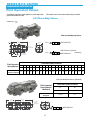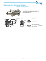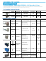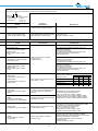
1
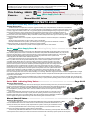
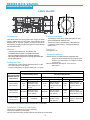
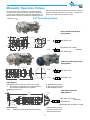
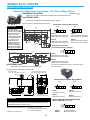
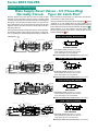
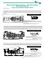
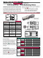
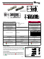
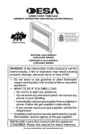
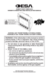
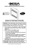
Control Valves and Components for
Process, Wellhead and Safety Shutdown Systems
BULLETIN
B316 2012
®
ISO 9001
CERTIFIED
www.versa-valves.com
e-mail: [email protected]
Versa Products Company, Inc., 22 Spring Valley Road, Paramus, New Jersey 07601 ● TEL: 201/843-2400 Fax: 201/843-2931
Versa BV., Prins Willem Alexanderlaan 1429, 7312 GB Apeldoorn, The Netherlands ● TEL: +01131-55-3681900 FAX: +01131-55-3681909
QUALITY IS
ABSOLUTE
Quality has no degrees at Versa.
There is no such thing as “pretty
good” or “almost right”. Every product is designed and manufactured to
conform to uniformly high standards.
These standards are assured by
a quality management system which
includes ISO 9001 certification and
testing of all products prior to shipment.
No matter how tough the application or environmental demands,
Versa offers you a choice of valves
to meet the challenge. Advanced design, durable construction materials
and rigid manufacturing standards
provide valves you can rely on for
years of trouble-free performance.
Be it a single valve or a pneumatic
system, Versa’s commitment to quality is uncompromising. Count on it.
THE COMMITMENT
CONTINUES
Fluid Power is our business. It is
our only business, so we have to be
good at it. Since its beginning in 1949,
Versa has maintained its commitment
to quality products and satisfied
customers.
Versa has succeeded in serving
industry’s needs with a broad line
of directional control devices. Our
focus on product variety, technical
expertise and company support
remains constant. It all begins with
a responsiveness to industry needs
and ends with delivery of the valve or
system you need—when you need it.
We view ourselves as problem
solvers and that role requires more
than making good products. It is what
we do before and after that is equally
important. From drawing board to
user satisfaction, our commitment is
continuous.
HOW WE PUT IT TOGETHER
IS WHAT SETS US APART
Versa is not the biggest manufacturer of directional control valves, so we try to be the best.
Design, manufacture, quality control, pricing, delivery – whatever the function – it must be geared to customer needs.
Many companies sell valves. At Versa, that is not enough. We sell satisfaction.
2
WORLDWIDE
ACCESSIBILITY
More than 500 fluid power representatives and over 100 stocking
locations comprise Versa’s worldwide distribution system. They
are supported by manufacturing
and technical centers in the United States and The Netherlands.
The distributor network is the
key to customer service and the
source of continuous application
feedback. Versa uses this input as
part of its research and development program in an effort to respond
to individual and industry needs.
Versa makes certain that our distributors’ sales and service personnel
receive factory training on an on-going basis. This includes basic theory,
product indoctrination and seminars.
Our distributor family is a source
of pride to Versa—but more important—it is a source of support
and service to all of our customers.
Contact Versa for the distributor
servicing your specific area.
Versa exercises diligence to assure that information contained in this catalog is correct, but does not accept responsibility for any errors or omissions. Versa also reserves the right to change or delete data or products at any
time without prior notification. To be sure the data you require is correct, consult factory.
This Catalog SERIES
Covers...
and
B
316
550
900
(Three-way Valves)
(Indicating Relay Valves)
(Main Supply Reset & Indicating Relay Valves)
Manual Shut-Off Valves
CONTENTS GUIDE
Series B316 Three-Way Valves (3/2) . . . . . . . . . . . . . . . . . . . . . . . . . . . . . . . . . Page 4-14
General Description
The B316 Series is a complete line of compact, rugged Three-Way (3/2), side-ported valves, constructed of 316 stainless
steel (conforms to NACE standard MR-01-75). They are designed for use particularly in corrosive environments and to control
a variety of aggressive media as well as air. O ring packed poppets provide bubbletight sealing throughout the operating
pressure range and when used to operate small volume appliances this feature conserves valuable instrument air.
Actuations include solenoid/pilot (including those suitable for Ordinary, Hazardous or LOW-WATT service ), remote
pressure pilot, manual, and mechanical. Many combination actuators and special function types can also be provided.
Consult the factory for these items.
Solenoid actuated valves can be 2-position, single or double solenoid. A manual override option is available for
most types.
Remote pressure pilot models can be 2-position, single or double pilot.
Manually actuated valves are 2-position, push button panel mounting types and are offered with or without
guarded push buttons. An optional lid knob operated type is also available.
Mechanically actuated valves are 2-position and are supplied with a roller for cam interface.
Series B900 Main Supply Reset & Indicating Relay Valves . . . . . . . . . . . . . Page 16-21
General Description
The B900 Series is comprised of Three-Way (3/2) Manual/Pilot Operated Main Supply Reset valves and Three-Way
(3/2) Indicating Relay valves. All are constructed of 316 stainless steel (meets NACE standard MR-01-75). They are designed for use particularly in corrosive environments and to control aggressive media as well as air. O ring packed
poppets provide bubbletight sealing throughout the operating range and when used to operate small
volume appliances this feature saves valuable instrument air.
Main Supply Reset valves can function as master relay valves and are generally pilot operated-spring
return, 2-position valves that are provided additionally with a means of manual operation. The function
of the Main Supply Reset valve is to control the supply of pressure to a system or portion of a system. If
a problem is sensed at some point in the system, the Main Supply Reset valve will shift to dump system
pressure from that portion of the circuit controlled by that Main Supply Reset valve. The shifting of the Main
Supply Reset valve is accomplished by a pilot device which is an integral part of the valve. The pilot is
pressurized when the system is running normally, but when a problem is sensed, the pilot is depressurized
and the valve shuts off the pressure to the main system or that portion of the main system that the valve
controls. Several variations of reset are available. One example is a “latching pilot” whereby when pilot
pressure returns, the valve will not shift to open the supply to the main system until the valve is manually
reset. The manual portion of the reset can also be latching or non-latching. Most Main Supply Reset valves can also be equipped with an integral
visual indicator that indicates when pressure is present in the pilot chamber. Complete functional descriptions of each valve can be found on the
pages within this valve series.
Indicating Relay valves are of the First Out-Receiving or First Out-Transmitting type. They have two functions generally. First, to indicate visually on a panel that a circuit malfunction has occurred and secondly, to quickly exhaust operating pressure from the system through the Main Supply Reset valve.
Series B500 Indicating Relay Valves . . . . . . . . . . . . . . . . . . . . . . . . . . . . . . . . . .Page 21-22
General Description
The B550 Series Indicating Relay valves are Three-Way (3/2) First Out Indicating valves. They are of the First Out-Receiving type, First Out-Transmitting type or First Out-Bypass type. All are constructed of hard coated aluminum (MIL-A8625E, Type III, Class 1) to provide reasonable resistance to extreme environmental conditions. Bubbletight sealing, accomplished by employing wafer seals, conserves valuable instrument air throughout the operating
pressure range.
First out Indicating Relay valves have two functions. First, to indicate visually on a panel that a circuit
malfunction has occurred and secondly, to quickly exhaust operating pressure from the system through
the Main Supply Reset valve. The Indicating Relay valve with the Bypass function additionally provides the
means to bypass the specific malfunctioning circuit without shutting down associated circuits.
Manual Shut-Off Valves . . . . . . . . . . . . . . . . . . . . . . . . . . . . . . . . . . . . . . . . . . . . Page 15
General Description
For emergency shut down systems a Two-Way Manual Bleed valve and a Three-Way Manual Block & Bleed
valve are available. Both valves are constructed of 316 stainless steel (meets NACE standard MR-01- 75),
and may be used as panic valves to quickly depressurize the system in order to get immediate shut down.
The Two-Way Manual Bleed valve is closed during normal operation, but manual actuation or backpressure to the outlet port will dump system pressure to atmosphere.
The Three-Way Manual Block & Bleed valve connects the inlet to the outlet during normal operation. Manual actuation
or back-pressure to the exhaust port causes the inlet to be blocked while the outlet dumps system pressure to atmosphere.
3
SERIES B316 VALVES
STAINLESS STEEL CONSTRUCTION
3-WAY VALVES
Construction
Pressure and Media
Versa B316 Valves are spool poppet valves except for double
pilot and double solenoid valves which have balanced spools.
Standard size O ring seals, placed in accordance with Versa’s
Anti-Extrusion principle provides long trouble free service with little
and easy maintenance.
Materials
Electrical
See pages 8 to 14
- Valve body and actuating caps: 316 stainless steel
-
0 to 200 psig (14 bar); Air or Hydrocarbon gases or other
gases compatible with materials used.
Pressures for Pilot, or Solenoid/Pilot, or Manual & Pilot
Combination operated valves - see pages pertaining to
specific valve.
All internal wetted metal parts: 316 stainless steel NACE
approved materials (solenoid parts not NACE approved)
Valve Seals: FKM (fluorocarbon) O ring seals used as standard
Screws: stainless steel
Temperature Range
Solenoid Valves: The table below lists suggested suffix
options for various temperature ranges and/or types
of service. For temperatures or conditions not listed,
consult factory.
Manual, Mechanical, Pilot Valves: -10°F (-23°C) to
200°F (95°C).
Porting and Flow
- Valve ports are ¼” NPT; Pilot and solenoid ports are ⅛” NPT
- Flow area (orifice) is 0.196” (5mm)
- Cv (Kv) normally closed = 1.6 (23.2); normally open = 1.1 (16.0)
TYPE OF SERVICE
Temperature Range
(Medium/Ambient
Temperature)
Intermittent Duty Service
Continuous Duty Service
AC or DC
AC
DC
Coil
Solenoid Plunger*
Coil
Solenoid Plunger*
Coil
Solenoid Plunger*
150°F to 200°F
(65°C) (95°C)
Suffix
-HT
Suffix-3 (may be
inclusive in other
suffix options as it is
in -HT)
Suffix
-HT
Suffix-3 (may be
inclusive in other
suffix options as it is
in -HT)
Suffix
-HT
Suffix-3 (may be
inclusive in other suffix options as it is in
-HT)
120°F to 150°F
(50°C) (65°C)
Standard
Standard
Suffix -3 (may be
inclusive in other
suffix options)
Suffix
-HT
Suffix -3 (may be
inclusive in other suffix
options as it is in -HT)
-10°F to 120°F
(-23°C) (50°C)
Standard
Standard
Suffix -3 (may be
inclusive in other
suffix options)
Suffix-3 (may be
inclusive in other
suffix options)
Standard
* All solenoids for hazardous locations include suffix -3 as standard.
Installation, Filtration & Lubrication
Valves have no limitations on mounting orientation.
40-50 micron filtration recommended.
General purpose lubricating oil ISO, ASTM viscosity grade 32 recommended.
4
Suffix -3 (may be
Standard inclusive in other suffix
options)
Manually Operates Valves
button flush with the button guard to protect against accidental
actuation. Nominal operating force is 3.75 lbs. + .05 times line
pressure (or 3.25N x bar line pressure + 17N).
For palm, finger, knee or straight-line mechanical operation.
Can also be cam actuated if cam rise is gradual. Unguarded
type has button exposed above valve body approximately 1/8”,
which is distance required for full actuation. Guarded type has
3/2-(Three-Way) Valves
DIMENSIONS: Inch
mm
Button Operated (Guarded)/
Spring Return
.13
3.3
.50
12.7
1.0
25.4
3.31
84.0
.27
6.9 Ø
.31
7.9
WITH OPTION -43
1.37
34.8
A
N. O.
1.50
Ø 38.1
.34
8.6
1.0
25.4
1.66
42.1
.50
12.7
¼” NPT
3 PORTS
BSI-3306-P-316
IN EX
A
WITHOUT OPTION -43
N. C.
IN EX
BSI-3303-P-316 (closed
crossover)
BSI-3308-P-316
Button Operated (Unguarded)/
Spring Return
1.0
25.4 Ø MIN PANEL HOLE
N. O.
A
BSI-3307-P-316
IN EX
A
4.64
117.9
.15 TRAVEL
3.8
Ø 1.81
46
Suffix Options:
-43E Additional panel mount nut for flush front mounting -S Strong spring for applications with marginal lubrication; use requires 45% additional force to operate.
-294B Rubber button cover
0.16
4.1
N. C.
BSI-3309-P-316
IN EX
-S-25B Black plastic lid knob
-S-25G Green plastic lid knob
-S-25R Red plastic lid knob
Ø 1.81
46
6.42
163
Ø 1.0 MIN PANEL HOLE
25.4
Palm Button Operated/
Spring Return*
BIP-3303-316 (closed
crossover)
BIP-3309-316
MAX PANEL THICKNESS .50
12.2
*Pilot pressure req. 15-200 psi (1-14 bar)
WITH SUFFIX OPTION -43 .31
7.9
-25B Black plastic lid knob
-25G Green plastic lid knob
-25R Red plastic lid knob
Suffix Options:
-43E Additional panel mount nut for flush front mounting
5
SERIES B316 VALVES
STAINLESS STEEL CONSTRUCTION
Pilot Operated Valves
Pilot medium can be other than medium being controlled.
Controlled by a pressure signal applied to a small integral pilot
piston that actuates the valve.
3/2-(Three-Way) Valves
DIMENSIONS: Inch
mm
Pilot Operated/Spring Return
.13
3.3
.50
12.7
1.0
25.4
3.31
84.0
1.25 SQ
31.7
.27
6.9 Ø
N. O.
BSP-3306-316
N. C.
BSP-3303-316 (closed
crossover)
BSP-3308-316
⅛” NPT
PILOT PORT
.34
8.6
1.0
25.4
¼” NPT
3 PORTS
1.66
42.1
Pilot Operated
Spring Return
Minimum pilot
pressure required
Controlled (inlet) Pressure
psi
bar
0-20 0-1.5
18
1.25
psi
bar
psi
bar
psi
bar
psi
bar
psi
bar
psi
bar
psi
bar
psi
bar
40
3
60
4.1
80
5.5
100
6.8
120
8.2
140
10
160
11
180 12.5 200
psi
bar
14
20
1.4
22
1.5
24
1.7
26
1.8
28
2.0
30
2.15
32
2.3
34
2.5
2.5
36
Pilot Operated/Pilot Return: (detented)
Pilot Operated
Spring Return
(detented)
Pilot Pressure
Required
1.43
36.3
4.43
112.5
Controlled (inlet) Pressure
psi
bar
0-200
0-14
15-200
1-14
⅛” NPT
PILOT
PORTS 2
BPP-3308-316
6
Mechanically Operated Valves
3/2-(Three-Way) Valves
Can be operated by a cam or machine member from
any angle, but pressure angle should not exceed 15°
from vertical center line.
.13
3.3
.50
12.7
1.0
25.4
3.31
84.0
.27
6.9 Ø
0.15 max stroke
4.1
Cam Operated/
Spring Return
0.18
4.6
A
0.13 min stroke
3.5
N. O.
BSC-3306-316
IN EX
.34
8.6
1.0
25.4
1.66
42.1
¼” NPT
3 PORTS
A
1.25
31.7 sq.
N. C.
IN EX
7
BSC-3303-316 (closed
crossover)
BSC-3308-316
SERIES B316 VALVES
STAINLESS STEEL CONSTRUCTION
Solenoid/Pilot Operates Valves-
3/2-(Three-Way) Valves
Solenoid-Pilot actuated Series B316 valves are available with a variety of different solenoids for both nonhazardous and hazardous
locations. Basic details of actuators are listed below. For additional data consult factory.
Non Hazardous Locations Solenoids
Suffix
Identification
Protection
Classification
Area Classification
and (Gas Grouping)
Certification(Conformance)
Ingress
Protection
None or
-U
General Purpose
Indoor & Outdoor
CSA
NEMA 1,2,3
-HC
-HCC (Shown)
General Purpose
Indoor & Outdoor
CSA
NEMA 4,
IP65
HAZARDOUS LOCATION SOLENOIDS
Suffix
Identification
Protection
Classification
Area Classification
and (Gas Grouping)
Certification(Conformance)
Ingress
Protection
-XX
-LB-XX
Hazardous
Locations
CLASS I, DIV. 2 (A & B)
CLASS I, DIV. 1 (C & D)
CLASS II, DIV. 1 (E, F & G)
UL - CSA
Ex d IIB+H2 T3 to T6 Gb
IECEx
NEMA 7 & 9
-XN
(d) Flameproof
II 2 G Ex d IIB+H2 T3 to T6
-LB-XN
-XDBS*
-XDBT*
(d) Flameproof
(e) Increased Safety
EX II 2 G D
Ex d e IIC T* Gb
EX tb IIIC T* ºC Db
Class I Div I Grp B, C & D
Class I Div II Grp E, F & G
EX d IIC DIP A21 T6 T4
IECEx ATEX
P66
&
IP68
ATEX
ATEX - IECEx
-INMETRO
IP66, IP67,
& IP68
CSA
NEMA 4, 4X
6P
See “Miscellaneous” column page 9 for ordering information.
-XMAA
-XMAE
-XMAF
-XMAG
-XMFA
-XMFE
-XMFF
-XMFG
-XIFA
-XIFE
-XIFF
(mb) Encapsulation
(e) Increased Safety
(tD) Tight Dust
(ia) Intrinsic Safe
-XISX6
-XISC
Intrinsic Safe
Ex e mb II T5, T6 Gb
Ex tD A21 T100ºC, T85ºC Db
IECEx
II 2 G Ex e mb II T5, T6
II 2D Ex tD A21 T100ºC, T85ºC
ATEX
Ex (ia) IIC T4...T6 Gb
Ex (ia) IIIC T130ºC, T80ºC Db
IECEx
II 2 G Ex ia IIC T4...T6
II 2 D Ex iaD 21 T130ºC, T80ºC
ATEX
II 2 G EEx ia IIC T6
ATEX
Class I, Groups (A, B, C & D)
Class II, Groups (E, F, &G)
Class III
*Consult factory for XDAS and XDAT operators.
8
IP66
&
IP67
IP66
&
IP67
IP65
Factory Mutual CSA
PRODUCT NUMBER COIL CODES: Complete product numbers require, when applicable, a coil code that represents the desired coil current type, frequency and
voltage. The coil code takes the form shown below, with ratings and voltage substituted as required.
Rating Code
A = 60Hz frequency
D = Direct Current (DC)
E = 50Hz frequency
Voltage
(Indicated by three digits:
as example,
24 volts = 024
120 volts = 120.
Voltage
(Power)
All usual 50 Hz & 60 Hz AC (6W)
All usual DC (7W)
Electrical
Characteristics
Class F epoxy molded coil (155ºC).
Continuous duty, 2 leads 24” (60 cm).
Miscellaneous
Steel cover with 1/2 NPT conduit entry.
24V60, 120V60, 240V60 (8.5W)
24V50, 110V50, 220V50 (8.5W)
12VDC, 24VDC, 48VDC (10.5W)
Class F epoxy molded coil (155ºC), with 3
spade terminals and mini DIN socket with
PG9 cable gland. Continuous duty.
3 spade terminals & DIN connector with PG9
cable gland: (-HC)
1/2 NPT conduit entry: (-HCC)
Voltage
(Power)
Electrical
Characteristics
Miscellaneous
All usual 50 Hz & 60 Hz AC (5.6W)
All usual DC (7.2W)
Plated steel coil housing with 1/2 NPT conduit entry.
For stainless steel (182FM) coil housing add: (-ST)
Plated steel coil housing
with 1/2 NPT conduit entry.
For stainless steel (182FM ) coil housing add: (-ST)
Maximum pilot pressure 120 psi (8 bar).
1.8W nominal power.
12V60, 24V60, 48V60, 120V60,
240V60 (1.8W)
6VDC, 12VDC, 24VDC, 48VDC
(1.8W)
All usual 50 Hz & 60 Hz AC (5.6W)
All usual DC (7.2W)
Class F epoxy molded coil (155ºC).
Continuous duty.
3 leads 24” (60 cm).
Plated steel coil housing
with M20 x 1.5 conduit entry.
Ground terminal on cover.
For stainless steel (182FM) coil housing add: (-ST)
Maximum pilot pressure 120 psi (8 bar)
1.8W nominal power.
12V60, 24V60, 48V60, 120V60,
240V60 (1.8W)
6VDC, 12VDC, 24VDC, 48VDC
(1.8W)
24VDC (D024)
120V60 (A120) 110V50 (E110)
230V50 (E230)
1.8 Watt standard, for lower watt
contact factory.
Plated steel coil housing
with M20 x 1.5 conduit entry.
Ground terminal on cover.
For stainless steel (182FM) coil housing add: (-ST)
Stainless steel coil housing with
internal Junction Box. Internal and
external ground screw.
Epoxy molded coils rated for continuous
duty, Class H – 180°C.
24VDC (4W)
(Consult factory for other voltage
options)
Continuous duty. Coil & Rectifier, including surge suppression, potted within
housing.
24VDC
(10W inrush, 2.6W holding)
(Consult factory for other voltages)
Continuous duty. Coil & Power Controller
potted with in housing.
Standard (vent to atmosphere)
1/8” Adapter (-H2E)
1/4” Adapter (-H2)
Dust Nut (-L14)
Suffix Detail Ordering Code
M 20 Connection
½” Connection
No Diode Diode No Diode Diode
XDBS1 XDBS5 XDBT1 XDBT5
XDBS2 XDBS6 XDBT2 XDBT6
XDBS3 XDBS7 XDBT3 XDBT7
XDBS4 XDBS8 XDBT4 XDBT8
Thick wall epoxy coil housing with integral
junction box. Internal ground terminal.
M20 x 1.5 conduit entry: (-XMAA), (-XMFA),
Cable gland for 6-12 mm ø cable: (-XMAE), (-XMFE)
1/2 NPT conduit entry with adapter: (-XMAF), (-XMFF)
Cable gland for 9-16 mm ø cable: (-XMAG), (-XMFG)
24VDC (0.8W)
(Consult factory for other voltages)
Continuous duty. Coil and power controller potted within housing.
requires the use of an approved safety barrier or isolator.
Thick wall epoxy coil housing and integral
junction box. Internal ground terminal.
M20 x 1.5 conduit entry: (-XIFA)
Cable gland for 6-12 mm ø cable: (-XIFE)
1/2 NPT conduit entry with adapter: (-XIFF)
24VDC
system voltage prior to barrier
(1.6 watt max.)
Class F epoxy molded coil (155ºC).
Continuous duty.
Requires the use of an approved barrier or isolator.
Maximum operating system voltage before barrier 28VDC.
Maximum pilot pressure 115 psi (8 bar).
3 spade terminals & DIN connector with PG9
cable gland: (-HC)
1/2 NPT conduit entry: (-HCC)
9
SERIES B316 VALVES
STAINLESS STEEL CONSTRUCTION
Solenoid/Pilot Operated Valves
A low power solenoid controls a built-in pilot which provides
the positive force for shifting the valve spool. When used with
a spring return the valve will be actuated when the solenoid is
energized and will return when the solenoid is de-energized.
When used in pairs for 2-position valves, the solenoid need
only be engergized momentarily in order to shift the valve. The
valve will then remain in the shifted position until signalled to
return by the opposite solenoid.
through internal passages, to the solenoid-pilot. In this type
valve, only one pressure connection, the inlet, is necessary.
EXPilot — requires a separate auxiliary pressure line to the
solenoid-pilot. Should be used when valve is controlling vacuum, when pressure will be below the minimum recommended
for INPilot operation or when viscosity of controlled medium is
such that it will impede the speed of actuation. In any case, the
pressure source may be either air or liquid and is independent
of the medium which is being controlled by the valve.
INPilot — utilizes the pressure from the inlet of the valve,
Valves For Nonhazardous Locations - 3/2-(Three-Way) Valves
DIMENSIONS: Inch
mm
Solenoid-Pilot Operated/
Spring Return
1.0
25.4
2.09
53.2
Manual
Ø .27
6.9 3 Mounting Holes Override
(Option)
0.5
12.7
0.44
0.88 11.2
22.4
0.13
3.3
Single
Solenoid Valves
EXPilot
Auxiliary Min. pilot
pressure required
2.0
50.8
1.0
25.4
5.08
129
2.05
52.1
⅛” NPT
Expilot
port
A
Electrical
Conduit Hub
½” NPT
N. O.
A
IN EX
IN EX
EXPilot type
EXPilot type
INPilot type
INPilot type
BSG-3308-316-(*)
BSG-3303-316-(*)
10-32 NF
Solenoid
Exhaust
N. C.
BSG-3326-316-(*)
BSG-3328-316-(*)
(*) Specify Options (page 11) & coil code (page 9).
Controlled (inlet) Pressure
psi
bar
0-20 0-1.5
18
1.25
psi
bar
psi
bar
psi
bar
psi
bar
psi
40
3
60
4.1
80
5.5
100
6.8
120
8.2 140
20
1.4
22
1.5
24
1.7
26
1.8
28
2.0
Single
Solenoid Valves
INPilot
Auxiliary pilot
pressure required
bar
psi
30
bar
psi
bar
psi
bar
psi
bar
10
160
11
175
12
200
14
2.15
32
2.3
34
2.4
36
2.5
Controlled (inlet) Pressure
psi
bar
18-175
1.25 to 12
None
None
10
DIMENSIONS: Inch
mm
Solenoid-Pilot Operated/
Solenoid-Pilot Return; (detented)
8.33
211.6
3.38
85.9
2.48
63
4.05
111.6
A
IN EX
24 Lead
610 Length
INPilot type
EXPilot type
⅛” NPT
Expilot port
1.2
30.5
2.77
6.53
BGG-3308-316-(*)
BGG-3328-316-(*)
(*) Specify Options (below) & coil code (page 9).
⅛” NPT
Expilot port
Controlled (Inlet) Pressure
Solenoid-pilot operated
Solenoid-Pilot return
(detented)
Auxiliary pilot
pressure required
EXPilot
INPilot
psi
bar
psi
bar
0-200
0-14
15-175
1-12
15-175
1-12
none
none
Suffix Options:
-3
CONTINUOUS DUTY SOLENOID and/or HIGH AMBIENT
OR MEDIA TEMPERATURE:
Recommended when coil may
be energized for long periods
and/or when ambient or media
temperature will exceed 120°F
(50°C). Standard on all solenoids for hazardous locations.
-H2 THREADED SOLENOID-PILOT
-HT CLASS H COIL: Recommended
-ME MANUAL OVERRIDE: Manually
EXHAUST: Adapter attaches
to solenoid to provide 1/8 NPT
threaded port for piping of solenoid exhaust.
pressurized pilot of solenoid pilot
actuator. Unguarded type push
and hold to operate. Use for setup or when power to solenoid is
absent.
for applications above 150°F
(65°C) and for DC continuous
duty above 120°F (50°C). Not
available with DIN style coil and
connector.
-HC DIN STYLE COIL & CONNEC-
TOR: DIN type coil with 3 spade
terminals and mini-DIN connector with PG9 cord grip. NEMA 4/
IP65.
11
SERIES B316 VALVES
STAINLESS STEEL CONSTRUCTION
Valves For Hazardous Locations - 3/2-(Three-Way) Valves
HAZARDOUS LOCATIONS
Valves with -XX or -LB-XX type solenoids are UL listed and CSA approved.
(d) FLAMEPROOF
Valves with -XN or -LB-XN type solenoids are ATEX certified.
See page 8/9 for additional solenoid details.
DIMENSIONS: Inch
mm
Solenoid-Pilot Operated/
Spring Return
1.52
38.6
5.47
139
2.0
50.8
.13
3.3
.50
12.7
Manual
Override
(Option)
1.0
25.4
Electrical
Conduit Hub
½” NPT
A
N. O.
A
IN EX
1.26 SQ
32
.34
8.6
1.0
25.4
1.66
42.1
.27
6.9 Ø ¼” NPT
3 Holes 3 PORTS
⅛” NPT
Expilot
port
2.90
73.6
10-32 NF
Solenoid
Exhaust
N. C.
IN EX
EXPilot type
BSG-3306-316-†-(*)
EXPilot type
BSG-3308-316-†-(*)
INPilot type
BSG-3326-316-†-(*)
INPilot type
BSG-3328-316-†-(*)
PRESSURES
Controlled (inlet) pressure & auxiliary pilot pressure (when required) are
the same as those shown for the corresponding solenoid valve for nonhazardous locations, Pages 10 & 11.
Solenoid-Pilot Operated/
Solenoid-Pilot Return; (detented)
8.43
214.1
3.43
87.1
4.17
105.9
2.60
66
A
IN EX
24
610 LONG LEADS
2 power & 1 ground (green)
1.2
30.5
2.77
6.53
EXPilot type
BGG-3308-316-†-(*)
⅛” NPT
Expilot
ports 2
† Specify solenoid identification detail.
-LB-XN: -LB-XX: -XN: -XX: (d) Flameproof; ATEX certified; low-watt; M20 x 1.5 conduit entry.
Hazardous Locations; UL listed & CSA approved; low-watt, 1/2 NPT conduit entry.
(d) Flameproof; ATEX certified; M20 x 1.5 conduit entry.
Hazardous Locations; UL listed & CSA approved; 1/2 NPT conduit entry.
-H2: -ME: -PC: -ST: Threaded pilot exhaust adapter, 1/8 NPT
Manual override
Coil potted within housing
Stainless steel (182 FM) coil housing
(*) Specify options (below) & coil code (page 9):
12
INPilot type
BGG-3328-316-†-(*)
Valves For Hazardous Locations - 3/2-(Three-Way) Valves
(d) FLAMEPROOF
(e) INCREASED SAFETY
Valves with -XDBS or -XDBT type solenoids are ATEX IEC CSA INMETRO certified.
See page 8/9 for additional solenoid details.
DIMENSIONS: Inch
mm
Solenoid-Pilot Operated/Spring Return
N. O.
⅛” NPT OR ¼” NPT SOLENOID ADAPTER OPTIONAL (SUFFIX -H2 OR -H)
CAN BE ROTATED
THROUGH 360°
.75
19.1
ø
1.5
38.1
EXTERNAL
GROUND
CONNECTION
4.68
118.9
¼” NPT (3 PORT)
3.47
88.1
.63
15.9
⅛” NPT PILOT
PORT (EX-PILOT
VALVES ONLY)
1.13
28.8
A
A
IN EX
IN EX
2.5
63.5
CONDUIT ENTRY
½” NPT FOR XDBS
OR
M20X1.5 FOR XDBS
.63
15.9
N. C.
4.12
104.7
1.75
44.5
.66
16.8
.66
16.8
EXPilot type
BSG-3306-316-XDB†-(*)
EXPilot type
BSG-3308-316-XDB†-(*)
INPilot type
BSG-3326-316-XDB†-(*)
INPilot type
BSG-3328-316-XDB†-(*)
Solenoid-Pilot Operated/
Solenoid-Pilot Return; detented (not shown)
1.12
28.5
A
PRESSURES
Controlled (inlet) pressure & auxiliary pilot pressure (when required) are
the same as those shown for the corresponding solenoid valve for nonhazardous locations, Pages 10 & 11.
Suffix Options:
-H2 -H Threaded solenoid-pilot exhaust adapter, with ⅛” NPT thread
Threaded solenoid-pilot exhaust adapter, with ¼” NPT thread
IN EX
EXPilot type: BGG-3308-316-XDB†-(*)
INPilot type: BGG-3328-316-XDB†-(*)
† Specify solenoid S: M20 x 1.5 conduit entry
identification detail. T: ½” NPT conduit entry
(*) Specify options (at left) & coil code (page 9).
(m) ENCAPSULATION
(e) INCREASED SAFETY
Valves with -XMA† or -XMF† type solenoids are ATEX certified.
ADAPTER (OPTIONAL)
⅛” OR ¼” NPT OR G⅛ OR G¼ (S.D. -H2 OR -H)
COIL CAN BE ROTATED TO FRONT OR
BACKSIDE OR TURNED UPSIDE-DOWN
2.56
65
TOP VIEW
2.36
60
4.22
107.1
.55
14
4.22
107.1
PRESSURES
6.08
154
CONDUIT ENTRY
SEE IDENTIFICATION DETAIL
⅛” NPT PILOT PORT
(FOR EXPILOT VALVES ONLY)
Solenoid-Pilot Operated/ Spring Return
A
N. O.
IN EX
EXPilot type:
INPilot type:
BSG-3306-316-XMA†-(*)
BSG-3306-316-XMF†-(*)
BSG-3326-316-XMA†-(*)
BSG-3326-316-XMF†-(*)
†Specify solenoid identification detail.
(*) Specify coil code (page 9).
A
N. C.
IN EX
Controlled (inlet) pressure & auxiliary pilot
pressure (when required) are the same as those
shown for the corresponding solenoid valve for
nonhazardous locations, Pages 10 & 11.
Solenoid-Pilot Operated/
Solenoid-Pilot Return; detented (not shown)
A
IN EX
BSG-3308-316-XMA†-(*)
BGG-3308-316-XMA†-(*)
BGG-3308-316-XMF†-(*)
BSG-3308-316-XMF†-(*)
BGG-3328-316-XMA†-(*)
BSG-3328-316-XMA†-(*)
BGG-3328-316-XMF†-(*)
BSG-3328-316-XMF†-(*)
A: M20 x 1.5 conduit entry;
F: ½” NPT conduit entry;
E: Cable gland for 6-12 mm ø cable;
G: Cable gland for 9-16 mm ø cable
13
SERIES B316 VALVES
STAINLESS STEEL CONSTRUCTION
Valves For Hazardous Locations - 3/2-(Three-Way) Valves
HAZARDOUS LOCATIONS
DIMENSIONS: Inch
mm
Valves with -HC-XISC or HCC-XISC are CSA and Factory Mutual approved.
(ia) INTRINSIC SAFE
Valves with -HC-XISX6 or HCC-XISX6 are ATEX certified.
See page 8/9 for additional solenoid details.
PRESSURES
Controlled (inlet)
pressure & auxiliary pilot
pressure (when required)
are the same as those
shown for the corresponding solenoid valve
for nonhazardous locations, Pages 10 & 11,
EXCEPT maximum
auxiliary pilot pressure
for EXPilot valves &
maximum controlled (inlet) pressure for INPilot
valves is 115 psi (8 bar).
OPTIONAL
OVERRIDE
.13
3.3
N. O.
5.52
140
1.38
35.1
2.0
50.8
A
A
1.34
34
IN EX
.78
19.4
¼” NPT
Ports 3
Solenoid-Pilot Operated/ Spring Return
IN EX
EXPilot
BSG-3306-316-HC-XIS†-D024
BSG-3306-316-HCC-XIS†-D024
EXPilot
BSG-3308-316-HC-XIS†-D024
BSG-3308-316-HCC-XIS†-D024
INPilot
INPilot
BSG-3326-316-HC-XIS†-D024
BSG-3326-316-HCC-XIS†-D024
⅛” NPT
Expilot
port
N. C.
BSG-3328-316-HC-XIS†-D024
BSG-3328-316-HCC-XIS†-D024
Solenoid-Pilot Operated/
Solenoid-Pilot Return; detented
A
.43
10.9
2.0
50.8
9.14
232
1.38
35.1
IN EX
EXPilot
BGG-3308-316-HC-XIS†-D024
BGG-3308-316-HCC-XIS†-D024
1.18
90.0
INPilot
(ib) INTRINSIC SAFE
BGG-3328-316-HC-XIS†-D024
BGG-3328-316-HCC-XIS†-D024
⅛” NPT
Expilot
port 2
.77
19.6
† Specify solenoid identification detail. C or X6 (See page 8/9
for solenoid details).
Valves with -XIF† type solenoids are ATEX approved.
See page 8/9 for additional solenoid details.
ADAPTER (OPTIONAL)
⅛” OR ¼” NPT OR G⅛ OR G¼ (S.D. -H2 OR -H)
COIL CAN BE ROTATED TO FRONT OR
BACKSIDE OR TURNED UPSIDE-DOWN
2.56
65
Solenoid-Pilot Operated/ Spring Return
N. O.
4.22
107.1
N. C.
A
A
4.22
107.1
IN EX
6.08
154
†CONDUIT ENTRY
SEE IDENTIFICATION DETAIL
⅛” NPT PILOT PORT
(FOR EXPILOT VALVES ONLY)
PRESSURES
Controlled (inlet) pressure & auxiliary pilot pressure (when required)
are the same as those shown for the corresponding solenoid valve for
nonhazardous locations, Pages 10 & 11.
†Specify solenoid identification detail.
A: M20 x 1.5 conduit entry;
E: Cable gland for 6-12 mm ø cable;
F: ½” NPT conduit entry;
(*) Specify coil code (page 9).
14
IN EX
EXPilot
BSG-3306-316-XIF†-(*)
EXPilot
BSG-3308-316-XIF†-(*)
INPilot
INPilot
BSG-3326-316-XIF†-(*)
BSG-3328-316-XIF†-(*)
Solenoid-Pilot Operated/ Solenoid-Pilot
Return; detented (not shown)
A
IN EX
EXPilot
INPilot
BGG-3308-316-XIF†-(*)
BGG-3328-316-XIF†-(*)
MANUAL SHUT-OFF VALVES
STAINLESS STEEL CONSTRUCTION
General Description
Designed for use in emergency shut down systems,
Manual Shut-Off valves are available in two types.
The Two-Way (2/2) valve is designated as a Block &
Bleed valve. When the panel knob is pulled out, supply
pressure is dumped to atmosphere.
The Three-Way (3/2) valve is designated as a Charge &
Bleed valve. In the normal operating mode of this valve
the inlet port is connected to the outlet port and the exhaust port is blocked. When the panel knob is pulled
out, supply pressure to the outlet port is blocked and the
downstream pressure is dumped to atmosphere.
Any backpressure to the outlet port of either valve while
functioning in the normal mode, will cause the valve to
shift as if the panel knob were pulled out.
OPERATING PRESSURE
AND WEIGHT
Weight
SYSTEM PRESSURE
ALLOWABLE BACKPRESSURE
at Outlet Port (Two-Way)
or Exhaust Port (Three-Way)
Two-Way (2/2)
Block & Bleed
MS02-3-316
0.77 lbs.
(.35kg)
0-150 psi
(0-10 bar)
0
Three-Way (3/2)
Charge & Bleed
MS03-3-316
1.0 lbs.
(.45 kg)
0-150 psi
(0-10 bar)
0
Porting Size and Flow
Materials
-
Inlet, outlet & exhaust ports: ¼” NPT
Internal orifice: ⅜” (9.5 mm) ø
Valve body and caps: 316 stainless steel (meets NACE
Standard MR-01-75)
Valve Seals: FKM (Fluorocarbon) O rings
Screws: stainless steel
Lid Knob: synthetic resin.
Installation
Valves have no limitations on mounting orientation. Valves
can be panel mounted. Panel hole required: 1” (25.4 mm) ø
TWO-WAY (2/2)
BLOCK & BLEED
Product Number
Button Color
MSO2-3-316
Red
MSO2-3-316-125B
Black
THREE-WAY (3/2)
CHARGE & BLEED
Product Number
Button Color
MSO3-3-316
Black
MSO3-3-316-125B
Red
DIMENSIONS: Inch
mm
Ø 1.81
46
.31 MAX PANEL
7.9 2 LOCK NUT
.31 MAX PANEL
7.9 2 LOCK NUT
4.70
119.3
3.79
96.1
2.61
66.4
.92
23.3
.50 MAX PANEL
12.7 1 LOCK NUT
3.53
89.5
.50 MAX PANEL
12.7 1 LOCK NUT
¼” NPT
PORT
.92
23.3
EX
OUT
IN
EX
15
IN
¼” NPT
PORT
Series B900 VALVES
STAINLESS STEEL CONSTRUCTION
Main Supply Reset Valves
General Description
Air Latch Pilot - when pressurized will not actuate the
valve until knob is pulled out. Pressure in the pilot chamber
can then hold the valve in the actuated position, and will
unlatch the knob actuator if the latching feature is included.
Main Supply Reset Valves are Manual/Pilot operated, Spring Return, Three-Way (3/2), normally closed valves that are generally
used to control and monitor the air pressure supply to an instrument control system. Monitoring is accomplished through the
use of a monitor pilot, which is an integral part of the valve and
which reacts to pressure signals from sensors within the system
in order to shut down that specific portion of the system, should
a malfunction occur.
Construction
The action of the valve for shut down and the method by which
the control system pressure is restored differentiates the various
Main Supply Reset valves available.
Materials
Knob Actuator —
The manual portion of the valve provides a lid knob which can
be pulled out to actuate the valve, in order to start up or reset the
control system pressure. A latch can be provided such that, once
actuated, the valve can be manually latched in the actuated position. Unlatching might be accomplished by pulling on the knob or
by applying pressure to the pilot.
An optional visual indicator, which is an integral part of the knob,
can also be provided in order to indicate when pressure in the
pilot chamber is actuating the valve.
All knob actuators are equipped for panel mounting utilizing a
panel mounting nut which is included.
Air Pilot Actuator —
The air pilot portion of the valve is a small cylinder which is an
integral part of the valve. The types available are:
Air Pilot - when pressurized will actuate the valve, and will unlatch the knob actuator if the latching feature is included.
Versa B900 Valves are spool poppet valves. Standard size O
ring seals, placed in accordance with Versa’s Anti-Extrusion
principle provides long trouble free service with little and easy
maintenance.
-
Valve body and actuating caps: 316 stainless steel
All internal wetted metal parts: 316 stainless steel or NACE
approved materials
Valve Seals: FKM (Fluorocarbon) O ring seals
Screws: stainless steel
Porting
- Valve ports are 1/4 NPT; Pilot ports are 1/8 NPT
- Flow area/Cv; consult factory
Pressure and Media
- 0 to 200 psig (14 bar); Air or Hydrocarbon gases or other
gases compatible with materials used.
- Pressures for Pilot: see pages pertaining to specific valve.
Temperature Range
Medium/Ambient temperature: -10°F (-23°C) to 200°F (95°C)
Installation, Filtration & Lubrication
Valves have no limitations on mounting orientation. 40-50
micron filtration recommended. General purpose lubricating
oil ISO, ASTM viscosity grade 32 recommended.
MAIN SUPPLY RESET VALVES SELECTOR
Knob Actuator
Non-latching
Manual Pin Latch
Pilot Actuator
Non-indicating
X
X
X
X
Indicating
Air Pilot
X
X
X
X
X
-159E
(page 17)
-301ES
(page 18)
X
900N
(page 18)
X
X
X
Air Latch Pilot
Valve
Suffix
900A
(page 17)
X
X
X
X
X
X
900
(page 18)
900P
(page 17)
X
X
900W
(page 18)
X
900PR
(page 19)
X
Manually resets valve
plus, a built-in pilot
(separate from Air Latch
Pilot) enables valve to
be reset from a remote
location utilizing a pilot
pressure signal.
X
X
X
Functions same as Air
Latch Pilot, but pilot
signal is controlled by
built-in solenoid.
X
X
X
X
Functions same as Air Latch Pilot plus, will trip if outlet port (which is connected to indicator valve loop) loses pressure, as in the case of a leak
16
900G
(page 19)
900NF
(page 19)
Main Supply Reset Valves - 3/2 (Three Way)
Normally Closed
Type: Air Pilot*
These valves can be actuated (open to flow) by a pilot signal
or manually by pulling the knob when there is no pilot signal.
When the pilot signal is removed or drops below 7 psi (0.5
bar), or the knob is released when there is no pilot pressure,
the valve will spring return to close the flow.
manual pin latch, pull the knob or apply a pilot signal.
Valves provided with a pressure indicator will appear red
(black character “R” is also visible) when there is no pressure in the pilot chamber or the pilot pressure drops below
7 psi (0.5 bar), at which point the spring will return the valve
to close the flow. The pressure indicator will appear green
(black character “G” is also visible) when there is pilot pressure present in the pilot chamber.
Valves provided with the manual pin latch feature can be
latched in the actuated position (open to flow) when there is
no pilot pressure, by pushing the manual latch pin and holding
it in while the knob is pulled out and released. To release the
DIMENSIONS: Inch
mm
1.81
46.0
Knob: Non-Latching, Non-Indicating
6.42
163
0.58 MAX PANEL
14.2 THICKNESS
0.5
12.7
NC CYLINDER
PORT
0.5
12.7
CYL
.44
11.2
.44
11.2
1.37
34.8
1.37
34.8
WRENCH FLAT
1.0 MIN PANEL
Ø 25.4 HOLE
EX
BIA-3309-316-159E
* Pilot signal required: 25-200 psi (1.7-14 bar) When available pilot signal will not be less than 40 psi, Suffix Option -S is recommended.
Maximum allowable exhaust backpressure: 5 psi (0.3 bar)
Knob: Latching, Non-Indicating
MANUAL LATCH PIN
1.82
Ø 46.2
IN
0.27
Ø
(3 MOUNTING HOLES)
6.8
Ø
CYL
1.0
MIN PANEL HOLE
25.4
OPTIONAL EXTRA PANEL NUT (SUFFIX “-43E”)
1.25
31.6
⅛” NPT PILOT PORT
IN
EX
BAA-3309-900A
.16
TRAVEL
4.1
.66
16.8
.38 MAX PANEL
9.7 THICKNESS
.66
16.8
* Pilot signal required: 25-200 psi (1.7-14 bar) When available pilot signal will not be less than 40 psi, Suffix Option -S is recommended.
Maximum allowable exhaust backpressure: 5 psi (0.3 bar)
1.43
36.3
6.42
163
Knob: Latching, Indicating
MANUAL PIN LATCH. REF.
1.5
(38.0)
INDICATOR DEVICE REFFERENCE
●
• RED INDICATES THAT THERE IS NO
PRESSURE IN THE PILOT CHAMBER
●• GREEN INDICATES THAT THE PILOT CHAMBER
IS PRESSURIZED AND THE VALVE IS IN THE
ACTUATED POSITION
RED
GREEN
1.0
(25.4) MIN PANEL HOLE DIA.
CYL
IN
EX
BAA-3309-900P
⅛” NPT
PILOT LATCH
PORT
17
* Pilot signal required: 25-200 psi (1.7-14 bar) When available pilot signal will not be less than 40 psi, Suffix Option -S is recommended.
Maximum allowable exhaust backpressure: 5 psi (0.3 bar)
Series B900 VALVES
STAINLESS STEEL CONSTRUCTION
Main Supply Reset Valves - 3/2 (Three-Way)
Normally Closed
Type: Air Latch Pilot*
knob is pulled out and released. To release the manual latch,
pull the knob or apply a pilot signal.
Pressure applied to the pilot latch port will not cause the pilot
chamber to be pressurized until the knob is manually pulled
out. Pilot pressure will then hold the valve open to flow against
the spring. If the pilot pressure drops below 7 psi (0.5 bar) the
spring will shift the valve to close the flow, and even if the pilot
signal is restored, the valve will remain closed until the knob is
manually pulled out.
Valves provided with a pressure indicator will appear red (black
character “R” is also visible) when the pilot chamber is not
pressurized. The pilot chamber cannot be pressurized until the
knob is pulled out at which point the indicator will appear green
(black character “G” is also visible). If the pilot signal is then
lost the spring will return the valve to close the flow and the
indicator will appear red (R).
Valves provided with the manual latch feature can be latched in
the actuated position (open to flow) when there is no pilot pressure, by pushing the manual latchpin and holding it in while the
Knob: Non-Latching, Non-Indicating
DIMENSIONS: Inch
mm
WRENCH FLAT
1.37 WRENCH FLAT
34.8
1.0
Ø
MIN PANEL HOLE
25.4
.5
.5
12.7
12.7
.37
9.4
Ø
CYL
.27
(3 MOUNTING HOLES)
6.9
⅛” NPT INLINE
PILOT LATCH
PORT
.44
11.2
1.26
32 SQ
.44
11.2
MAX PANEL
THICKNESS
.16
TRAVEL
4.1
.56
14.2
5.98
152
1.0
25.4
2.0
50.8
IN
.63
16
1.0
25.4
EX
BIA-3309-316-301ES
1.0
25.4
* Pilot signal required: 25-200 psi (1.7-14 bar) When available pilot signal will not be less than 40 psi, Suffix Option -S is recommended.
Maximum allowable exhaust backpressure: 5 psi (0.3 bar)
Knob: Non-Latching, Indicating
1.37 WRENCH FLAT
34.8
1.0
Ø 25.4 MIN PANEL HOLE
.5
.5
12.7
12.7
.37
WRENCH FLAT
9.4
Ø
.27
(3 MOUNTING HOLES)
6.9
⅛” NPT INLINE
PILOT LATCH
PORT
.44
11.2
1.26
32 SQ
.44
11.2
TRAVEL
.16
4.1
MAX PANEL
THICKNESS
.56
14.2
2.0
50.8
1.0
25.4
RED
GREEN
.63
16
1.0
25.4
1.0
25.4
CYL
IN
EX
BAA-3309-900N
* Pilot signal required: 25-200 psi (1.7-14 bar) When available pilot signal will not be less than 40 psi, Suffix Option -S is recommended.
5.98
152
INDICATOR DEVICE REFERENCE
● RED INDICATES THAT THERE IS NO PRESSURE IN THE PILOT LATCH CHAMBER.
● GREEN INDICATES THAT THE PILOT LATCH CHAMBER IS PRESSURIZED AND THE VALVE IS IN THE ACTIVATED POSITION
Maximum allowable exhaust backpressure: 5 psi (0.3 bar)
Knob: Latching, Non-Indicating
MANUAL
LATCH
PIN
CYL
⅛” NPT INLINE
PILOT LATCH
PORT
IN
EX
BAA-3309-900
* Pilot signal required: 25-200 psi (1.7-14 bar) When available pilot signal will not be less than 40 psi, Suffix Option -S is recommended.
Maximum allowable exhaust backpressure: 5 psi (0.3 bar)
Knob: Latching, Indicating
WRENCH FLAT
.37
9.4
MANUAL
LATCH
PIN
1.37 WRENCH FLAT
34.8
1.0
Ø
MIN PANEL HOLE
25.4
.5
.5
12.7
12.7
Ø
.27
(3 MOUNTING HOLES)
6.9
⅛” NPT INLINE
PILOT LATCH
PORT
.44
11.2
1.26
32 SQ
.44
11.2
TRAVEL
.16
4.1
MAX PANEL
THICKNESS
7.30
185.3
.56
14.2
2.0
50.8
1.0
25.4
1.0
25.4
.63
16
.5
12.7
1.0
25.4
INDICATOR DEVICE REFERENCE
● RED INDICATES THAT THERE IS NO PRESSURE IN THE PILOT LATCH CHAMBER.
● GREEN INDICATES THAT THE PILOT LATCH CHAMBER IS PRESSURIZED AND THE VALVE IS IN THE ACTIVATED POSITION
RED
GREEN
CYL
IN
EX
BAA-3309-900W
* Pilot signal required: 25-200 psi (1.7-14 bar) When available pilot signal will not be less than 40 psi, Suffix Option -S is recommended.
Maximum allowable exhaust backpressure: 5 psi (0.3 bar)
18
Main Supply Reset Valves - 3/2 (Three-Way)
Normally Closed
Type: Specialized Application
DIMENSIONS: Inch
mm
Description Function is the same as Air Latch Pilot types on page 18 except that internal connection from CYL port to pilot
provides the valve with a means to trip the valve closed to flow should a leak or other loss of pressure occur in the indicator loop
line that connects “Indicator valves” to the pilot port. This feature eliminates need for separate connection from CYL port to “Indicator valves”.
INDICATOR DEVICE REFERENCE
● RED INDICATES THAT THERE IS NO PRESSURE IN THE PILOT LATCH CHAMBER.
● GREEN INDICATES THAT THE PILOT LATCH CHAMBER IS PRESSURIZED AND THE VALVE
IS IN THE ACTIVATED POSITION
OPTIONAL EXTRA PANEL NUT (SUFFIX “43E”)
Knob: Non-Latching, Indicating
⅛” NPT PILOT
EXHAUST PORT
RED
GREEN
¼” NPT (3 PORTS)
1.0 MIN. PANEL HOLE ø
1.63
41.4
.63
16
MAX. PANEL THICKNESS (SUFFIX “43E”) .38
9.7
7.30
185.3
.56
14.2
MAX. PANEL
THICKNESS
2.0
50.8
1.0
25.4
CYL
IN
EX
BAA-3309-900NF
Controlled Pressure: 0-75 psi (10-5.1 bar)
Pilot pressure required: 25-75 psi (1.7-5.1 bar) to maintain air latch
When available pilot signal will not be less than 40 psi, Suffix Option -S is recommended.
1.0
25.4
7.46 MAX
189.4
Maximum allowable exhaust backpressure: 5 psi (0.3 bar)
Description Function is the same as Air Latch Pilot types on page 18, but valve is additionally equipped with a Remote Pilot
so that the valve can be reset with a remote pilot signal as well as manually. However, the manual pin latch is not activated by the
remote pilot signal, so the valve will remain reset only as long as the remote pilot signal remains intact. Generally, this feature is
useful where the Main Supply Reset valve is somewhat inaccessible and allows the operator to reset the valve from a separate
location, until the operator is able to get to the station and activate the pin latch.
Knob: Latching, Non-Indicating
Latching pilot
CYL
IN
EX
Remote pilot
BAA-3309-900PR
Controlled Pressure: 0-200 psi (10-14 bar)
* Pilot pressure required: 50-200 psi (3.4-14 bar) to unlatch manual pin and to maintain air latch or actuate remotely
Maximum allowable exhaust backpressure: 5 psi (0.3 bar)
Description Function is the same as Air Latch Pilot types on page 18, except Air Latch Pilot is solenoid controlled. Electrical signal causes pressure to be admitted to the pilot chamber from valve inlet through an internal passage to pilot, but Air Latch
Pilot is not activated until knob is manually pulled out. The manual pin latch can be activated once the solenoid is de-energized.
24” (610mm) LEADS
MANUAL LATCH PIN
MANUAL OVERRIDE BUTTON
OPTIONAL (SUFFIX -ME)
Knob: Latching, Non-Indicating
CYL
.47
11.8
2.09
53.2
IN
EX
BAA-3309-900G-(*)
*Specify coil code Page 9
.66
16.8
2.98
75.7
.66
16.8
2.0
50.8
Controlled Pressure: 25-120 psi (1.7-8.2 bar)
25 psi (1.7 bar) minimum to unlatch manual pin or to maintain air latch
When available inlet pressure will not be less than 40 psi, Suffix
Option -S is recommended.
Maximum allowable exhaust backpressure: 5 psi (0.3 bar)
⅛” NPT PILOT PORT
(EX-PILOT VALVES ONLY)
3.42
86.9
8.4
213.4
19
Series B900 & B550 VALVES
STAINLESS STEEL
HARDCOATED ALUMINUM
CONSTRUCTION
Indicating Relay – Pilot Monitoring Valves
Indicating Relay valves are used to monitor the pilot actuators
of the Main Supply Relay valves listed on pages 16-19. The
Indicating Relays have two functions. First, to indicate visually
on a panel that a circuit malfunction has occurred and secondly, to quickly cause operating pressure to exhaust from the
system through the Main Supply Relay valve, allowing a valve
operator or pneumatic system to shut-down. When placed in
series with other Indicating Relays, only the relay indicator of
the relay controlling the circuit for which a malfunction is
sensed will show red (R).
Three types of Indicating Relays are available:
First Out Indicator-Transmitting type (page 20)
First Out Indicator-Receiving type (page 21)
First Out Indicator-Bypass type (page 22)
FIRST OUT INDICATOR/INDICATING RELAY-TRANSMITTING TYPE
PILOT EXHAUST
(SIGNAL)
DIRECTION OF
AC TUATION
(INDICATOR)
GREEN
RED
BAA-3308-900R
Dimensions are approximate.
Consult factory for actual
dimensions of specific valves.
Construction:Body.
WRENCH FLAT 1.37
34.8
BAA-3308-550R
Ø
1.0
MIN PANEL HOLE
25.4
.50
.50
12.7 12.7
Ø
.27 (3 MOUNTING
6.9 HOLES)
Internals, Caps
316 stainless steel
(NACE MR-01-75)
Stainless steel
Fasteners-
FKM (fluorocarbon) O rings
SealsPressures:
Working (Controlled)
pressure range-
25-130 psi (1.7-8.8 bar)
Maximum allowable
exhaust backpressurePilot trip/reset-
5 psi (0.3 bar)
See Charts A & B below
Hardcoated Aluminum
(MIL-A-8625E, Type III, Class1)
Stainless steel
.56
14.2
FKM (fluorocarbon) O rings
¼” NPT (3 PORT)
5 psi (0.3 bar)
See Charts A & B below
Flow:
Consult Factory
Media:
Air - 40 to 50 micron filtration
recommended
Panel Mount (1”ø hole)
Red (black character “R”)
Green (black character “G”)
1.08
27.4 1.38
35.1
2.0
50.8
6.21
157.7
Air - 40 to 50 micron filtration
recommended
Porting:
Valve PortsPilot Ports-
2.38
60.5
⅛” NPT PILOT EXHAUST PORT
15-120 psi (1- 8.2 bar)
Consult Factory
1/4” NPT
1/8” NPT
1.0
25.4
MAX PANEL
THICKNESS
Transmitting Relay Circuit
(system in mode A - working range)
Indicating Relays-Transmitting type
1/4” NPT
1/8” NPT
to main
system
Mounting & Installation:
Panel Mount (1”ø hole)
Indicator colors:
Trip mode (depressurized)- Red (black character “R”)
Working mode (pressurized)- Green (black character “G”)
Sensor
Sensor
Sensor
Main Supply Relay Valve
e.g. BAA-3309-900W See page 18.
(Consult factoru for other color availibility)
Pressure Chart “A” (working range): Indicating Relay-Transmitting type
Operation Mode A
Flow path is open between the Relay inlet and
“CYL” port whenever both the Relay inlet and
pilot pressure are within the working pressure range in Chart A. In this condition the
Relay indicator is green (G). If the Relay inlet
pressure is lost while in this mode, the Relay
flow position and indicator color will remain
unchanged.
Operation Mode B
Flow path is open between the Relay “CYL”
port and exhaust port whenever the Relay pilot
chamber backpressure does not exceed the
specifications in Chart B. In this condition the
Relay indicator is red (R). The relay will automatically reset to operation mode A when both
the Relay inlet and pilot pressure return to the
working range, as indicated in Chart A
Indicating
Relay Valve
Inlet Pressure
Minimum
Reset- Pilot
Pressure
BAA-3308-900R
BAA-3308-550R
BAA-3308-900R
BAA-3308-550R
PSIG
—
—
25
30
40
50
60
70
BAR
—
—
1.7 2.0
2.7
3.4
4.1
4.8 5.4 6.1
80
6.8
80
90
7.5 8.2 8.8
PSIG
15
20
—
30
40
50
60
70
100 110 120
—
BAR
1.0
1.4
—
2.0
2.7
3.4
4.1
4.8 5.4 6.1
6.8
7.5 8.2
—
PSIG
—
—
25
30
37
45
54
63
77
85
92 100 110
6.3 6.8 7.5
72
90
100 110 120 130
BAR
—
—
1.7 2.0
2.5
3.1
3.7
4.3 4.9 5.2
5.8
PSIG
15
18
—
24
29
35
40
46
57
61
65
74
—
BAR
1.0
1.2
—
1.6
2.0
2.4
2.7
3.1 3.5 3.9
4.2
4.4 5.0
—
51
Pressure Chart “B” (shut-down range): Indicating Relay-Transmitting type
Indicating
Relay Valve
Inlet Pressure
Minimum TripPilot Pressure
BAA-3308-900R
BAA-3308-550R
BAA-3308-900R
BAA-3308-550R
20
PSIG
—
—
25
30
40
50
60
70
BAR
—
—
1.7 2.0
2.7
3.4
4.1
4.8 5.4 6.1
80
6.8
PSIG
15
20
—
30
40
50
60
70
100 110 120
80
90
90
100 110 120 130
7.5 8.2 8.8
—
BAR
1.0
1.4
—
2.0
2.7
3.4
4.1
4.8 5.4 6.1
6.8
7.5 8.2
—
PSIG
—
—
10
16
22
28
35
42
57
63
70
85
BAR
—
—
0.7 1.1
1.5
1.9
2.4
2.9 3.4 3.9
4.3
4.8 5.2 5.8
PSIG
1
4
—
10
15
21
26
32
44
47
53
59
—
—
0.7
1.0
1.4
1.8
2.2 2.5 3.0
3.2
3.6 4.0
—
BAR 0.07 0.3
50
37
77
FIRST OUT INDICATOR/INDICATING RELAY-RECEIVING TYPE
CYL
PILOT EXH
DIRECTION OF
ACTUATION
(INDICATOR)
GREEN
RED
Dimensions are approximate.
Consult factory for actual
dimensions of specific valves.
.77
19.6
.77
19.6
Ø
1.0
MIN PANEL HOLE
25.4
Ø
.27
(3 MOUNTING HOLES)
6.9
.50
12.7
IN
EX
1.28 SQ
7.17
182.1
.66
16.8
2.9
53.1
2.36
60
1.89
48
4.47
113.5
.54
13.7
1.0
25.4
IN
⅛” NPT PILOT
EXHAUST PORT
2.22
56.4
.56
14.2
MAX PANEL
THICKNESS
PILOT
1.33
33.8
1.05
26.7
1.70
43.2
⅛” NPT PILOT
INLET PORT
1.34
34.0
3.47
88.1
.50
12.7
¼” NPT (3 PORT)
¼” NPT (3 PORT)
BAA-3308-900RA
316 Stainless Steel (NACE MR-01-75)
Stainless steel
FKM (ASTM D-1418) (ISO-1629)–
(fluorocarbon) O rings
25-130 psi (1.7-8.8 bar)
5 psi (0.3 bar)
BAA-3308-550RA
Construction:
Body, Internals, Caps
Fasteners
Hardcoated Aluminum
(MIL-A-8625E, Type III, Class1)
Stainless steel
Seals
FKM (fluorocarbon) O rings
Pressures:
Working (Controlled) Pressure Range
15-120 psi (1-8.2 bar)
Maximum allowable Exhaust backpressure
5 psi (0.3 bar)
Inlet Pressure
25-130 psi (1.7-8.8 bar)
Consult Factory
Air
1/4” NPT
1/8” NPT
Panel mount (1”ø hole)
Red (black character “R”)
Green (black character “G”)
⅛” NPT PILOT
Pilot trip/reset
psi (bar)
15 (1.0)
30 (2.0)
50 (3.4)
70 (4.8)
90 (6.1)
110 (7.5)
120 (8.2)
Flow:
Controlled flow
Media:
(40 to 50 micron filtration recommended)
Porting: Valve Ports
Pilot Ports
Min. Reset
Max. Trip
Pilot Pressure Pilot Pressure
9 (0.6)
3 (0.2)
14 (1.0)
6 (0.4)
23 (1.6)
12 (0.8)
31 (2.1)
20 (1.4)
38 (2.6)
27 (1.8)
46 (3.1)
33 (2.2)
50 (3.4)
37 (2.5)
Consult Factory
Air
1/4” NPT
1/8” NPT
Mounting & Installation:
Panel Mount (1”ø hole)
Indicator Colors: Trip mode (depressurized)
Working mode (pressurized)
(Consult factory for other color availability)
Red (black character “R”)
Green (black character “G”)
Receiving Relay Circuit
Operation Mode A
Flow path is open between the Relay inlet and “CYL” port whenever the
pilot pressure from the process monitor and the Relay inlet pressure is in
the working pressure range. In this condition the Relay indicator is green
(G). If the loss of inlet pressure occurs while in this mode, the relay flow
position and indicator color will remain unchanged.
(system in mode A - working range)
Sensor
Indicating RelaysReceiving type
Sensor
Operation Mode B
Upon loss of the pilot signal or decrease to the minimum trip pressure,
the Relay will shift to block the inlet and to open the exhaust to the “CYL”
port. In this condition the indicator shows red (R). The Relay will not reset to green (G) until both sufficient pilot and inlet pressure are restored
into the Relay.
21
Sensor
to main system
Main Supply Relay Valve
e.g. BAA-3309-900W
See page 18.
Series B900 & B550 VALVES
STAINLESS STEEL
CONSTRUCTION
HARDCOATED ALUMINUM
Indicating Relay – Pilot Monitoring Valves
FIRST OUT INDICATOR/INDICATING RELAY-RECEIVING TYPE WITH INTEGRAL BYPASS
The First Out Indicator with an integral bypass combines the
functions of two valves into one. Its primary function is that of
the First Out Indicator/Indicating Relay-Receiving type (BAA3308-550RA or BAA-3308-900RA) as shown on page 21. Additionally, an integral bypass valve enables specific circuits to
be bypassed in the event of a malfunction, without shutdown
of the entire system. The additional piping, fittings and labor
usually required to accomplish this feature are thus eliminated
through the use of the Bypass type Indicating Relay valve. The
bypass is accomplished by manually rotating (90°) a detented
lever as part of the valve.
OUT
GREEN
RED
INDICATOR
IN
EX
Dimensions are approximate.
Consult factory for actual
dimensions of specific valves.
PILOT
(SENSOR)
BYPASS ACTUATOR HANDLE. SHOWN IN NON-BYPASS MODE,
ROTATE HANDLE THUR 90° COUNTERCLOCKWISE FOR BYPASS
8.16
207.3
2.86
72.6
1.88
47.6
BYPASS
5.30
134.6
1.33
33.8
1.70
43.2
1.15
29.2
1.31
33.3
1.25
31.6
0.5
12.7
¼” NPT THREE PORTS
(3) PLACES
⅛” NPT PORT
BAA-3308-550RAB
Construction:
Body, Internals, Caps
Hardcoated Aluminum (MIL-A-8625E, Type III, Class 1)
Seals
Fasteners & Bypass lever
FKM (fluorocarbon)
stainless steel
Pressures:
Working (Controlled) pressure range
15-120 psi (1-8.2 bar)
Maximum allowable exhaust backpressure
5 psi (0.3 bar)
Inlet Pressure
15 (1.0)
30 (2.0)
50 (3.4)
70 (4.8)
90 (6.1)
110 (7.5)
120 (8.2)
Min. Reset
Max. Trip
Pilot Pressure Pilot Pressure
9 (0.6)
3 (0.2)
14 (1.0)
6 (0.4)
23 (1.6)
12 (0.8)
31 (2.1)
20 (1.4)
38 (2.6)
27 (1.8)
46 (3.1)
33 (2.2)
50 (3.4)
37 (2.5)
Pilot trip/reset
psi (bar)
Flow:
Consult factory
Air
40 to 50 micron filtration recommended
1/4” NPT
1/8” NPT
Media:
Porting: Valve ports
Pilot ports
Mounting & Installation:
Indicator Colors: Trip mode (depressurized)
Panel mount (1” ø hole)
Red (black character “R”)
Green (black character “G”)
Working mode (pressurized)
Consult factory for other color availability
22
Series B316 B550 B900 VALVES
Repair Kits & Information
CAUTION: Before attempting to repair any VERSA Valve,
always be certain that all pressure in the system including
the valve to be repaired, has been turned off and the system
and valve has been depressurized before proceeding with the
repair. Serious injury or death may occur if this procedure is
neglected.
VERSA Valves are designed and built to provide millions of
trouble free cycles. However, in the event that a valve should
require repair, most likely due to wear or some kind of abuse,
in most cases the valve can be restored to “new” condition by
the replacement of the valve seals. Kits containing the necessary items are available and are listed below, for specific valve
types.
Valve
Product Number
Repair
Kit Number
ALL
Manual-
*B-3308-316
BSI or BIA
Cam-
BSC
Pilot-
BSP or BPP
Solenoid
BSG or BGG
*Additional nonhazardous
solenoid parts not included
in kit:
(nonhazardous &
hazardous location)
VALVES
P-1005-08 Solenoid Plunger
P-1005-02-(Coil Code) Coil
For valves with Suffix Option -EP add -EP to product number listed above.
Valve
Product Number
Air Pilot
type
Air Latch Pilot
type
Repair
Kit Number
BIA-3309-316-159E
*B-3308-316
BAA-3309-900A
BAA-3309-900P
**BIA-3309-316-301ES
**BAA-3309-900
**BAA-3309-900N
**BAA-3309-900W
*B-3308-316-900
**BAA-3309-900NF
**BAA-3309-900PR
**BAA-3309-900G
*Additional solenoid parts
not included in kit:
P-1005-08 Solenoid Plunger
P-1005-02-(Coil Code) Coil
For valves with Suffix Option -EP add -EP to product number listed above.
INDICATING RELAY
Valves
-900 type
-550 type
Valve
Product Number
Repair
Kit Number
BAA-3308-900R
BAA-3308-900RA
B-3308-316-900
BAA-3308-550R
BAA-3308-550RA
B-3308-550RA
BAA-3308-550RAB
B-3308-550RAB
For valves with Suffix Option -EP add -EP to product number listed above.
23
**These valves are equipped with easy access pilot cap assem-
blies which can be removed with a crescent or open-end type wrench in order to remove the valve plunger assembly while the valve is still mounted in the panel.
WARNINGS REGARDING THE DESIGN APPLICATION,
INSTALLATION AND SERVICE OF VERSA PRODUCTS
The warnings below must be read and reviewed before designing a system utilizing, installing,
servicing, or removing a Versa product. Improper use, installation or servicing of a Versa
product could create a hazard to personnel and property.
DESIGN APPLICATION WARNINGS
Versa products are intended for use where compressed air or industrial hydraulic fluids are
present. For use with media other than specified or for non-industrial applications or other
applications not within published specifications, consult Versa.
Versa products are not inherently dangerous. They are only a component of a larger system.
The system in which a Versa product is used must include adequate safeguards to prevent
injury or damage in the event of system or product failure, whether this failure be of switches,
regulators, cylinders, valves or any other system component. System designers must provide
adequate warnings for each system in which a Versa product is utilized. These warnings,
including those set forth herein, should be provided by the designer to those who will come in
contact with the system.
Where questions exist regarding the applicability of a Versa product to a given use, inquiries
should be addressed directly to the manufacturer. Confirmation should be obtained directly
from the manufacturer regarding any questioned application prior to proceeding.
INSTALLATION, OPERATION AND SERVICE WARNINGS
Do not install or service any Versa product on a system or machine without first depressurizing
the system and turning off any air, fluid, or electricity to the system or machine. All applicable
electrical, mechanical, and safety codes, as well as applicable governmental regulations and
laws must be complied with when installing or servicing a Versa product.
Versa products should only be installed or serviced by qualified, knowledgeable personnel
who understand how these specific products are to be installed and operated. The individual
must be familiar with the particular specifications, including specifications for temperature,
pressure, lubrication, environment and filtration for the Versa product which is being installed
or serviced. Specifications may be obtained upon request directly from Versa. If damages
should occur to a Versa product, do not operate the system containing the Versa product.
Consult Versa for technical information.
LIMITED WARRANTY DISCLAIMER AND
LIMITATION OF REMEDIES
Products sold by Versa are warranted to be free from defective material and workmanship for a period of ten years from the date of manufacture, provided said items are used
in accordance with Versa specifications. Versa’s liability pursuant to that warranty is
limited to the replacement of the Versa product proved to be defective provided the allegedly defective product is returned to Versa or its authorized distributor.
Versa provides no other warranties, expressed or implied, except as stated above. There
are no implied warranties of merchantability or fitness for a particular purpose. Versa’s
liability for breach of warranty as herein stated is the only and exclusive remedy and in no
event shall Versa be responsible or liable for incidental or consequential damages.
www.versa-valves.com
e-mail: [email protected]