1
MikroElektronika
User’s manual
Development tools - Books - Compilers
www.mikroelektronika.co.yu
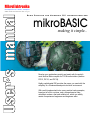
Basic Compiler for Microchip PIC microcontrollers
mikroBASIC
making it simple...
Develop your applications quickly and easily with the world's
most intuitive Basic compiler for PIC Microcontrollers (families
PIC12, PIC16, and PIC18).
Highly sophisticated IDE provides the power you need with the
simplicity of a Windows based point-and-click environment.
With useful implemented tools, many practical code examples,
broad set of built-in routines, and a comprehensive Help,
mikroBasic makes a fast and reliable tool, which can satisfy
needs of experienced engineers and beginners alike.
mikroBASIC User’s manual
Table of Contents
CHAPTER 1
mikroBasic IDE
Learn all about our advanced integrated
environment. Create projects, debug your code,
view statistics, and much more.
CHAPTER 2
mikroBasic Reference
BASIC language, syntax, and PIC specifics
CHAPTER 3
Built-In and Library Routines
Included routines allow you to create complex
applications quickly and easily. Many useful routines
for use with CAN, ADC, PDWM, CompactFlash, and
other modules are at your disposal.
MikroElektronika: Development tools - Books - Compilers
mikroBASIC
making it simple...
mikroBASIC - Basic Compiler for Microchip PIC microcontrollers
CHAPTER 1: mikroBasic IDE
1
Quick Overview
Code Editor
Basic Editor Features
Advanced Editor Features
Code Explorer
Creating First Project
Projects
Managing Source Files
Compile and Link Source Code
Debugger
Error Window
Assembly View
Statistics
Integrated Tools
Keyboard Shortcuts
1
3
3
4
6
7
13
14
16
17
19
20
21
24
26
CHAPTER 2: mikroBasic Reference
28
Identifiers
Keywords
Data Types
Array
Strings
Numerals and Character Strings
Constants
Symbols
Variables
Comments
Expressions
Declaration and Statements
Directives
Procedures And Functions
Units
Scope (Identifier Visibility)
Program Organization
Type Conversion
29
30
31
32
34
35
36
38
39
43
44
46
48
50
55
58
60
62
page
ii
MikroElektronika: Development tools - Books - Compilers
mikroBASIC
making it simple...
mikroBASIC - Basic Compiler for Microchip PIC microcontrollers
Assignment And Implicit Conversion
Implicit Conversion And Legal Expressions
Operators
Arithmetic Operators
Boolean Operators
Logical (Bitwise) Operators
Relation (Comparison) Operators
Conditional Statements
Labels and Goto
Case Statement
If Statement
Loops
For Statement
Repeat Statement
While Statement
ASM Statement
PIC MCU Specific
mikroBasic Specific
Compiler Error Messages
65
69
73
76
79
80
84
87
87
88
90
92
93
95
96
97
98
99
101
CHAPTER 3: Built-In and Library Routines
104
Built-In Routines
Library Routines
1-Wire Library
ADC Library
CAN Library
CANSPI Library
Compact Flash
EEPROM Library
I2C Library
LCD Library
PWM Library
RS485 Library
SPI Library
USART Library
Numeric Formatting Routines
Utilities
105
107
108
111
113
125
134
140
141
145
148
150
156
161
164
166
page
MikroElektronika: Development tools - Books - Compilers
iii
mikroBASIC
mikroBASIC - Basic Compiler for Microchip PIC microcontrollers
making it simple...
To readers note
DISCLAIMER:
The mikroBASIC compiler and this manual are owned by MikroElektronika and is protected
by copyright law and international copyright treaty. Therefore, you should treat this manual
like any other copyrighted material (e.g., a book). The manual and the compiler may not be
copied, partially or as a whole without the written consent from the MikroEelktronika. The
PDF-edition of the manual can be printed for private or local use, but not for distribution.
Modifying the manual or the compiler is strictly prohibited.
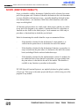
HIGH RISK ACTIVITIES
The mikroBASIC compiler is not fault-tolerant and is not designed, manufactured or intended
for use or resale as on-line control equipment in hazardous environments requiring fail-safe
performance, such as in the operation of nuclear facilities, aircraft navigation or communication systems, air traffic control, direct life support machines, or weapons systems, in which
the failure of the Software could lead directly to death, personal injury, or severe physical or
environmental damage ("High Risk Activities"). MikroElektronika and its suppliers specifically
disclaim any express or implied warranty of fitness for High Risk Activities.
LICENSE AGREEMENT:
By using the mikroBASIC compiler, you agree to the terms of this agreement. Only one person may use licensed version of mikroBASIC compiler at a time.
Copyright © MikroElektronika 2003 - 2004.
This manual covers mikroBASIC and the related topics. New versions may contain changes
without prior notice.
COMPILER BUG REPORTS:
The compiler has been carefully tested and debugged. It is, however, not possible to
guarantee a 100 % error free product. If you would like to report a bug, please contact us at
the address [email protected]. Please include next information in your bug
report:
- Your operating system
- Version of mikroBASIC
- Code sample
- Description of a bug
CONTACT US:
MikroElektronika magazine
Voice: +381 11 362 04 22, + 381 11 684 919
Fax:
+381 11 362 04 22
Web:
www.MikroElektronika.co.yu
E-mail: office@MikroElektronika .co.yu
PIC, PICmicro and MPLAB is a Registered trademark of Microchip company. Windows is a
Registered trademark of Microsoft Corp. All other trade and/or services marks are the
property of the respective owners.
page
iv
MikroElektronika: Development tools - Books - Compilers
C H A P T E R
1
mikroBasic IDE
QUICK OVERVIEW
mikroBasic is a Windows-based Integrated Development Environment, and is much
more than just Basic compiler for PIC MCUs. With mikroBasic, you can:
1.
2.
3.
4.
5.
6.
Create Basic source code using the built-in Code Editor
Compile and link your source code
Inspect program flow and debug executable logic with Debugger
Monitor variables in Watch Window
Get error reports
Get detailed statistics (how compiled code utilizes PIC MCU memory, hex
map, charts and more...)
MikroElektronika: Development tools - Books - Compilers
mikroBASIC
mikroBASIC - Basic Compiler for Microchip PIC microcontrollers
making it simple...
Watch
Window
Code
Explorer
Code
Editor
Breakpoints
Dialog
Error
Window
Code
Assistant
Code Editor features adjustable Syntax Highlighting, Code Assistant, Parameters
Assistant, Auto Correct for common typos, and Code Templates.
Code browser, Keyboard shortcut browser, and Quick Help browser are at your disposal for easier project management.
Error Window displays all errors detected during compiling and linking.
Watch Window enables you to monitor variables, registers and PIC MCU
memory.
New Project Wizard is fast, reliable, and easy way to create a project.
Source-level Debugger lets you debug executable logic step-by-step by watching
program flow.
Help files are syntax and context sensitive.
page
2
MikroElektronika: Development tools - Books - Compilers
mikroBASIC
making it simple...
mikroBASIC - Basic Compiler for Microchip PIC microcontrollers
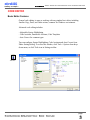
CODE EDITOR
Basic Editor Features
General code editing is same as working with any standard text-editor, including
familiar Copy, Paste, and Undo actions, common for Windows environment.
Advanced code editing includes:
- Adjustable Syntax Highlighting
- Code Assistant, Parameters Assistant, Code Templates
- Auto Correct for common typos
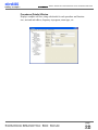
You can configure Syntax Highlighting, Code Assistant and Auto Correct from
Editor Settings dialog. To access this window, click Tools > Options from dropdown menu, or click Tools icon in Settings toolbar.
Tools Icon.
page
MikroElektronika: Development tools - Books - Compilers
3
mikroBASIC
mikroBASIC - Basic Compiler for Microchip PIC microcontrollers
making it simple...
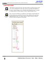
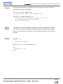
Advanced Editor Features
Code Assistant [CTRL+SPACE]
If you type first few letter of a word and then press CTRL+SPACE, all valid identifiers matching the letters you typed will be prompted to you in a floating panel
(see the image). Now you can keep typing to narrow the choice, or you can select
one from the list using keyboard arrows and Enter.
Parameter Assistant [CTRL+SHIFT+SPACE]
Parameter Assistant will be automatically invoked when you open a parenthesis
"(" or press CTRL+SHIFT+SPACE. If name of valid function or procedure precedes the parenthesis, then the expected parameters will be prompted to you in a
floating panel. As you type the actual parameter, next expected parameter will
become bold.
Code Template [CTR+J]
You can insert Code Template by typing the name of the template (for instance,
whileb), then press CTRL+J, and Editor will automatically generate code. Or you
can click button from Code toolbar and select template from the list.
You can add your own templates to the list. Just select Tools > Options from dropdown menu, or click Tools Icon from Settings Toolbar, and then select Auto
Complete Tab. Here you can enter the appropriate keyword, description, and code
of your template.
Auto Correct
Auto Correct corrects common typing mistakes. To access the list of recognized
typos, select Tools > Options from drop-down menu, or click Tools Icon from
Settings Toolbar, and then select Auto Correct Tab. You can also add your own
preferences to the list.
page
4
MikroElektronika: Development tools - Books - Compilers
mikroBASIC
making it simple...
Comment /
Uncomment Icon.
mikroBASIC - Basic Compiler for Microchip PIC microcontrollers
Also, Code Editor has feature to comment or uncomment selected block of code
by simple click of a mouse, using icons and from Code Toolbar.
Bookmarks
Bookmarks make navigation through large code easier.
CTRL+<number> : Goto bookmark
CTRL+SHIFT+<number> : Set bookmark
Goto Line
Goto Line option makes navigation through large code easier. Select Search >
Goto Line from drop-down menu, or use the shortcut CTRL+G.
page
MikroElektronika: Development tools - Books - Compilers
5
mikroBASIC
mikroBASIC - Basic Compiler for Microchip PIC microcontrollers
making it simple...
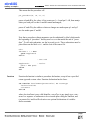
CODE EXPLORER
Find Declaration
Icon.
Collapse/Expand
All Icon.
Code Explorer is placed to the left of the main window by default, and gives clear
view of every declared item in the source code. You can jump to declaration of
any item by right clicking it, or by clicking the Find Declaration icon. To expand
or collapse treeview in Code Explorer, use the Collapse/Expand All icon.
Also, two more tab windows are available in Code Explorer: Keyboard Tab lists
all keyboard shortcuts, and QHelp Tab lists all the available built-in and library
functions and procedures, for a quick reference. Double-clicking a routine in
QHelp Tab opens an appropriate Help chapter.
page
6
MikroElektronika: Development tools - Books - Compilers
mikroBASIC
making it simple...
mikroBASIC - Basic Compiler for Microchip PIC microcontrollers
CREATING FIRST PROJECT
Step 1
From a drop-down menu, select: Project > New Project, or click New Project icon
New Project
Icon.
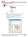
Step 2
Fill the New Project Wizard dialog with correct values to set up your new project.
- Select a device for your project from the drop-down menu
- Set configuration bits (Device Flags) by clicking Default push-button.
- Select Device Clock by entering appropriate value in edit box.
- Enter a name for your new project
- Enter project description edit box for closer information about your project
- Enter project path
page
MikroElektronika: Development tools - Books - Compilers
7
mikroBASIC
mikroBASIC - Basic Compiler for Microchip PIC microcontrollers
making it simple...
After you have set up your project, select OK push button in New Project Wizard
dialog box. mikroBasic will create project for you and automatically open the program file in code editor. Now we can write the source code.
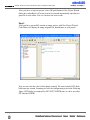
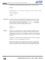
Step 3
After you have successfully created an empty project with New Project Wizard,
Code Editor will display an empty program file, named same as your project.
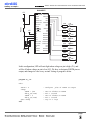
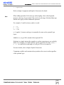
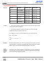
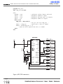
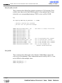
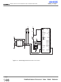
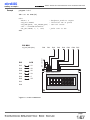
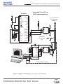
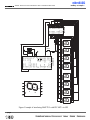
Now we can write the code for this simple example. We want to make LED diode
blink once per second. Assuming we have the configuration given in the following
figure, LED diodes are connected to PIC16F877 PORTB pins. (it can be any other
PIC that has PORTB)
page
8
MikroElektronika: Development tools - Books - Compilers
mikroBASIC
making it simple...
mikroBASIC - Basic Compiler for Microchip PIC microcontrollers
PIC16F877
+5V
10K
MCLR/Vpp/THV RB7/PGD
RA0/AN0
RB6/PGC
RA1/AN1
RB5
RA2/AN2/VrefRA3/AN3/Vref+
RB4
RB3/PGM
RA4/TOCKI
Reset
+5V
RE0/RD/AN5
RB0/INT
RE1/WR/AN6
Vdd
Vss
RE2/CS/AN7
Vdd
Vss
RD7/PSP7
RD6/PSP6
OSC1
RD5/PSP5
OSC2
RD4/PSP4
RCO/T1OSO
RC7/RX/DT
RC1/T1OSI
RC6/TX/CK
RC2/CCP1
RC5
RC3
4MHz
330R
RB2
RB1
RA5/AN4
330R
LB7
LB6
330R
LB5
330R
LB4
330R
LB3
330R
LB2
330R
LB1
RC4
RD0/PSP0
RD3/PSP3
RD1/PSP1
RD2/PSP2
330R
LB0
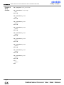
In this configuration, LED will emit light when voltage on pin is high (5V), and
will be off when voltage on pin is low (0V). We have to designate PORTB pins as
output, and change its value every second. Listing of program is below
program My_LED
main:
TRISB = 0
eloop:
PORTB = $FF
delay_ms(1000)
PORTB = 0
delay_ms(1000)
goto eloop
end.
' configure
'
'
'
'
'
turn
wait
turn
wait
stay
pins of PORTB as output
on diodes on PORTB
1 second
of diodes on PORTB
1 second
in a loop
page
MikroElektronika: Development tools - Books - Compilers
9
mikroBASIC
mikroBASIC - Basic Compiler for Microchip PIC microcontrollers
Compile Icon.
making it simple...
Step 4
Before compiling, it is recommended to save the project (menu choice File>Save
All). Now you can compile your code by selecting menu Run > Compile,
or by clicking the Compile icon.
mikroBasic has generated hex file which can be used to program PIC MCU. But
before that, let's check our program with the Debugger. Also mikroBasic generates
list and assembly files.
Debug Icon.
Step 5
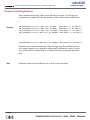
After successful compiling, we can use mikroBasic Debugger to check our program behavior before we feed it to the device (PIC16F877 or other). For a simple
program such as this, simulation is not really necessary, but it is a requirement for
more complex programs.
To start the Debugger, select Run > Debug, or click the Debug icon, or simply hit
F9.
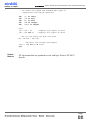
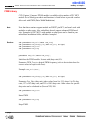
Upon starting the Debugger, Watch Window appears, and the active line in Code
Editor marks the instruction to be executed next. We will set the breakpoint at line
7 by positioning the cursor to that line and toggling the breakpoint (Run > Toggle
Breakpoint or F5). See the following image.
page
10
MikroElektronika: Development tools - Books - Compilers
mikroBASIC
making it simple...
mikroBASIC - Basic Compiler for Microchip PIC microcontrollers
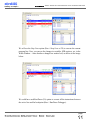
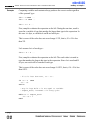
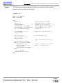
We will use the Step Over option (Run > Step Over or F8) to execute the current
program line. Now, you can see the changes in variables, SFR registers, etc, in the
Watch Window – items that have changed are marked red, as shown in the image
below.
We could have used Run/Pause (F6) option to execute all the instructions between
the active line and the breakpoint (Run > Run/Pause Debugger).
page
MikroElektronika: Development tools - Books - Compilers
11
mikroBASIC
mikroBASIC - Basic Compiler for Microchip PIC microcontrollers
making it simple...
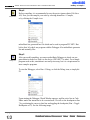
Step 6
Now we can use hex file and feed it to the device (PIC16F877 or other). In order
to do so hex file must be loaded in programmer (PIC Flash by mikroElektronika
or any other).
page
12
MikroElektronika: Development tools - Books - Compilers
mikroBASIC
making it simple...
mikroBASIC - Basic Compiler for Microchip PIC microcontrollers
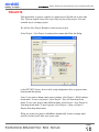
PROJECTS
Each application, or project, consists of a single project file and one or more unit
files. You can compile source files only if they are part of the project. First and
essential step is creating a project.
We will use New Project Wizard to create our new project.
Select Project > New Project from drop-down menu and follow the dialog:
(select PIC MCU device, device clock, setup configuration bits, set project name,
location and description)
Later, if you want to change some project settings, select Project > Edit from dropdown menu. To save your project , select Project > Save All from drop-down
menu. To save your project under different name, select Project > Save Project As
from drop-down menu. To open a project, select Project > Open, or Project >
Reopen from drop-down menu.
When you create new project, mikroBasic automatically creates an empty main
unit file in which you'll write your source code.
page
MikroElektronika: Development tools - Books - Compilers
13
mikroBASIC
mikroBASIC - Basic Compiler for Microchip PIC microcontrollers
making it simple...
Managing Source Files
Source files created in mikroBasic have the extension ppas. By default, main unit
file is named same as the project.
Location of the main unit source file and other project information are stored in
project file with extension ppp.
Creating Main Unit File
Main unit file is created simultaneously with the project and is named same as the
project, with extension ppas. You should not change the name of this file as
mikroBasic might not be able to compile it. Project file and main unit file must be
saved in the same folder.
Creating a New Unit File
Select File > New unit from drop-down menu, or press CTRL+N, or click the
New File icon.
A new tab will open, named "Untitled1". This is your new unit file. Select File >
Save As from drop-down menu to name it the way you want.
Keyword uses instructs compiler which unit beside main unit should be compiled.
Units other than main must be in same folder with project file or in folder specified by search path.
Search path can be configured by selecting menu choice Options > Settings from
drop-down menu and then tab window Advanced.
Opening an Existing File
Select File > Open from drop-down menu, or press CTRL+O, or click the Open
File icon. The Select Input File dialog opens. In the dialog, browse to the location
of the file you want to open and select it. Click the Open button.
The selected file is displayed in its own tab. If the selected file is already open, its
current Editor tab will become active.
page
14
MikroElektronika: Development tools - Books - Compilers
mikroBASIC
making it simple...
mikroBASIC - Basic Compiler for Microchip PIC microcontrollers
Printing an Open File
Make sure that window containing the file you want to print is the active window.
Select File > Print from drop-down menu, or press CTRL+P, or click the Print
icon. In the Print Preview Window, set the desired layout of the document and
click the OK button. The file will be printed on the selected printer.
Saving File
Make sure that window containing the file you want to save is the active window.
Select File > Save from drop-down menu, or press CTRL+S, or click the Save
icon. The file will be saved under the name of its window.
Saving File Under a Different Name
Make sure that window containing the file you want to save is the active window.
Select File > Save As from drop-down menu, or press SHIFT+CTRL+S. The New
File Name dialog will be displayed.
In the dialog, browse to the folder where you want to save the file.
In the File Name field, modify the name of the file you want to save.
Click the Save button.
Closing a File
Make sure that tab containing the file you want to close is the active tab.
Select File > Close from drop-down menu, or right click the tab of the file you
want to close in Code Editor.
If the file has been changed since it was last saved, you will be prompted to save
your changes.
page
MikroElektronika: Development tools - Books - Compilers
15
mikroBASIC
mikroBASIC - Basic Compiler for Microchip PIC microcontrollers
making it simple...
Compile and Link Source Code
Compile Icon.
When you have created the project and written the source code, you will want to
compile it. Select Run > Compile from drop-down menu, or click Compiler Icon
from Compiler Toolbar.
Progress bar will appear to inform you about the status of compiling. If no errors
are encountered, mikroBasic will produce hex file, assembly file, and list for the
appropriate PIC MCU.
page
16
MikroElektronika: Development tools - Books - Compilers
mikroBASIC
making it simple...
mikroBASIC - Basic Compiler for Microchip PIC microcontrollers
DEBUGGER
Source-level Debugger is integral component of mikroBasic development environment. It is designed to simulate operations of Microchip Technology's PIC MCU’s
and to assist users in debugging Basic software written for these devices.
Debug Icon.
Debug Icon.
Debugger simulates program flow and execution of instruction lines, but does not
fully emulate PIC device behavior: it does not update timers, interrupt flags, etc.
Jump to interrupt is performed by clicking the Interrupt icon .
After you have successfully compiled your project, you can run Debugger by
selecting Run > Debug from drop-down menu, or by clicking Debug Icon .
Starting the Debugger makes more options available: Step Into, Step Over, Run to
Cursor etc. Line that is to be executed is color highlighted (blue).
Debug [F9]
Starts Debugger.
Step Into [F7]
Execute the current Basic instruction (single or multiple cycle instructions) and
then halt. After execution, all windows are updated. If the instruction is a procedure or function call, execute it enters routine and halt at the first following
instruction after the call.
Step Over [F8]
Execute the current Basic instruction (single or multiple cycle instructions) then
halt. If the instruction is a procedure or function call, execute the called routine
and halt at the instruction following the call.
Run to cursor [F4]
Executes all instructions between the current instruction and the cursor position.
Toggle Breakpoints [F5]
Toggle breakpoint at current cursor position.
page
MikroElektronika: Development tools - Books - Compilers
17
mikroBASIC
mikroBASIC - Basic Compiler for Microchip PIC microcontrollers
making it simple...
Run/Pause Debugger [F6]
Run or pause Debugger.
Run > View Breakpoints
Invoke breakpoints window, with list of breakpoints. Double clicking item in window list locates breakpoint.
Watch Window
Watch Window allows you to monitor program items while running your program.
It displays variables and special function registers of PIC MCU, their addresses
and values. Values are updated as you go through the simulation. See the image
below.
Double clicking one of the items opens a window in which you can assign new
value to the selected variable or register.
page
18
MikroElektronika: Development tools - Books - Compilers
mikroBASIC
making it simple...
mikroBASIC - Basic Compiler for Microchip PIC microcontrollers
ERROR WINDOW
In case that errors were encountered during compiling, compiler will report them
and won't generate a hex file. Error Window will be prompted at the bottom of the
main window.
Error Window is located under message tab, and displays location and type of
errors compiler has encountered. Compiler also reports warnings, but these do not
affect generating hex code. Only errors can interefere with generation of hex.
Double clicking the message line in Error Window results in highlighting the line
of source code where the error took place.
page
MikroElektronika: Development tools - Books - Compilers
19
mikroBASIC
mikroBASIC - Basic Compiler for Microchip PIC microcontrollers
making it simple...
ASSEMBLY VIEW
Assembly Icon.
After compiling your program in mikroBasic, you can click toolbar Assembly icon
or select Project > View Assembly from drop-down menu to review generated
assembly code in a new tab window. Assembly is human readable with symbolic
names. All physical addresses and other information can be found in Statistics or
in list file.
If program is not compiled and there is no assembly file, starting this option will
compile your code and then display assembly.
page
20
MikroElektronika: Development tools - Books - Compilers
mikroBASIC
making it simple...
mikroBASIC - Basic Compiler for Microchip PIC microcontrollers
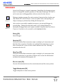
STATISTICS
Statistics Icon.
After successful compiling, you can review statistics on your code. Select Project
> View Statistics from drop-down menu, or click the Statistics icon. There are five
tab windows:
Memory Usage Window
Provides overview of RAM and ROM memory usage in form of histogram.
RAM Window
Summarizes all GPR and SFR registers and their addresses. Also displays symbolic names of variables and their addresses.
page
MikroElektronika: Development tools - Books - Compilers
21
mikroBASIC
mikroBASIC - Basic Compiler for Microchip PIC microcontrollers
making it simple...
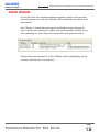
ROM Window
Lists op-codes and their addresses in form of a human readable hex code.
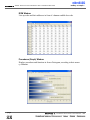
Procedures (Graph) Window
Displays procedures and functions in form of histogram, according to their memory allotment.
page
22
Chapter 1.
Integrated Development Environment - IDE
MikroElektronika: Development tools - Books - Compilers
mikroBASIC
making it simple...
mikroBASIC - Basic Compiler for Microchip PIC microcontrollers
Procedures (Details) Window
Displays complete call tree, along with details for each procedure and function:
size, start and end address, frequency in program, return type, etc.
page
MikroElektronika: Development tools - Books - Compilers
23
mikroBASIC
mikroBASIC - Basic Compiler for Microchip PIC microcontrollers
making it simple...
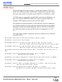
INTEGRATED TOOLS
USART Terminal
mikroBasic includes USART (Universal Synchronous Asynchronous Receiver
Transmitter) communication terminal for RS232 communication. You can launch
it from drop-down menu Tools > Terminal or by clicking the icon .
ASCII Chart
ASCII Chart is a handy tool, particularly useful when working with LCD display.
You can launch it from drop-down menu Tools > ASCII chart.
page
24
MikroElektronika: Development tools - Books - Compilers
mikroBASIC
making it simple...
mikroBASIC - Basic Compiler for Microchip PIC microcontrollers
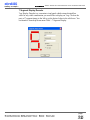
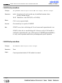
7 Segment Display Decoder
7seg Display Decoder is a convenient visual panel which returns decimal/hex
value for any viable combination you would like to display on 7seg. Click on the
parts of 7 segment image to the left to get the desired value in the edit boxes. You
can launch it from drop-down menu Tools > 7 Segment Display.
page
MikroElektronika: Development tools - Books - Compilers
25
mikroBASIC
mikroBASIC - Basic Compiler for Microchip PIC microcontrollers
making it simple...
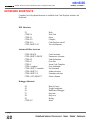
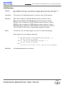
KEYBOARD SHORTCUTS
Complete list of keyboard shortcuts is available from Code Explorer window, tab
Keyboard.
IDE Shortcuts
F1
CTRL+N
CTRL+O
CTRL+F9
CTRL+F11
CTRL+SHIFT+F5
Help
New Unit
Open
Compile
Code Explorer on/off
View breakpoints
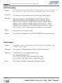
Advanced Editor shortcuts
CTRL+SPACE
CTRL+SHIFT+SPACE
CTRL+D
CTRL+G
CTRL+J
CTRL+<number>
CTRL+SHIFT+<number>
CTRL+SHIFT+I
CTRL+SHIFT+U
CTRL+ALT+SELECT
Code Assistant
Parameters Assistant
Find declaration
Goto line
Insert Code Template
Goto bookmark
Set bookmark
Indent selection
Unindent selection
Select columns
Debugger Shortcuts
F4
F5
F6
F7
F8
F9
CTRL+F2
Run to Cursor
Toggle breakpoint
Run/Pause Debugger
Step into
Step over
Debug
Reset
page
26
MikroElektronika: Development tools - Books - Compilers
mikroBASIC
making it simple...
mikroBASIC - Basic Compiler for Microchip PIC microcontrollers
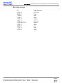
Basic Editor shortcuts
F3
CTRL+A
CTRL+C
CTRL+F
CTRL+P
CTRL+R
CTRL+S
CTRL+SHIFT+S
CTRL+V
CTRL+X
CTRL+Y
CTRL+Z
Find, Find Next
Select All
Copy
Find
Print
Replace
Save unit
Save As
Paste
Cut
Redo
Undo
page
MikroElektronika: Development tools - Books - Compilers
27
C H A P T E R
2
mikroBasic
Reference
‘Why Basic?’, you may wonder. Well, the answer is simple: it is legible, easy-tolearn, procedural programming language, with sufficient power and flexibility needed for programming microcontrollers. Whether you had any previous programming
experience, you will find that writing programs in mikroBasic is very easy.This
chapter will help you learn or recollect Basic syntax, along with the specifics of programming PIC Microcontrollers.
MikroElektronika: Development tools - Books - Compilers
mikroBASIC
making it simple...
mikroBASIC - Basic Compiler for Microchip PIC microcontrollers
IDENTIFIERS
Identifiers are names used for referencing the stored values, such as variables and
constants. Every program, procedure, and function must be identified (hence the
term) by an identifier.
Rules
Valid identifier:
1. must begin with a letter of English alphabet or possibly the underscore (_)
2. can be followed by alphanumeric characters and the underscore (_)
3. may not contain special characters:
~!@#$%^&*()+`-={}[]:";'<>?,./|\
mikroBasic is not case sensitive. First, FIRST, and fIrST are an equivalent identifier.
Note
Elements ignored by the compiler include spaces, new lines, and tabs. All these
elements are collectively known as the white space. White space serves only to
make the code more legible; it does not affect the actual compiling.
Several identifiers are reserved in mikroBasic - you cannot use them as your own
identifiers. Please refer to Kewords. Also, mikroBasic has several pre-defined
identifiers. Pre-defined identifiers are listed in the chapter Library Functions and
Procedures.
Examples
' Valid identifier examples
temperature_V1
Pressure
no_hit
dat
sum
vtext
' Some invalid identifier examples
7temp
%higher
xor
j23.07.04
'
'
'
'
cannot
cannot
cannot
cannot
begin with a numeral
contain special characters
match reserved word
contain special characters
page
MikroElektronika: Development tools - Books - Compilers
29
mikroBASIC
mikroBASIC - Basic Compiler for Microchip PIC microcontrollers
making it simple...
KEYWORDS
The following keywords (reserved words) cannot be redefined or used as identifiers.
absolute
and
asm
boolean
char
clear
div
double
end
for
goto
if
int
is
mod
next
or
procedure
float
select
string
then
module
include
wend
with
abs
array
begin
case
chr
const
do
else
exit
function
gosub
in
interrupt
loop
new
not
print
program
read
step
switch
to
until
dim
while
xor
In mikroBasic, all SFR (Special Function Registers) are defined as global variables and represent special reserved words that cannot be redefined. For example TMR0, PCL, STATUS, etc.
Also, mikroBasic has a number of predefined identifiers (refer to Library
Routines). These can be replaced by your own definitions, but that would impede
the functionality of mikroBasic.
page
30
MikroElektronika: Development tools - Books - Compilers
mikroBASIC
making it simple...
mikroBASIC - Basic Compiler for Microchip PIC microcontrollers
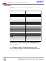
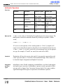
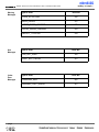
DATA TYPES
Type determines the allowed range of values for variable, and which operations
may be performed on it. It also determines the amount of memory used for one
instance of that variable.
Simple
Type
byte
char*
word
short
integer
longint
Size
8-bit
8-bit
16-bit
8-bit
16-bit
32-bit
Range of values
0 .. 255
0 .. 255
0 .. 65535
-128 .. 127
-32768 .. 32767
-2147483648 ..147483647
* char type can be treated as byte type in every aspect
Structured
Array represents an indexed collection of elements of the same type, often called
the base type. Base type can be any simple type.
String represents a sequence of characters. It is an array that holds characters and
the first element of string holds the number of characters (max number is 255).
Sign
Sign is important attribute of data types, and affects the way variable is treated by
the compiler.
Unsigned can hold only positive numbers:
byte
word
0 .. 255
0 .. 65535
Signed can hold both positive and negative numbers:
short
integer
longint
-128 .. 127
-32768 .. 32767
-2147483648 .. 214748364
page
MikroElektronika: Development tools - Books - Compilers
31
mikroBASIC
mikroBASIC - Basic Compiler for Microchip PIC microcontrollers
making it simple...
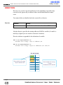
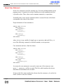
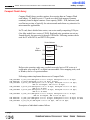
Array
Array is a set of data stored in consecutive memory locations. Defining an array
and manipulating its elements is simple. Elements of array are always of same
data type (any simple).
dim
dim
dim
days_of_the_week
as byte[7]
months
as byte[12]
AD_Conversion_result as word[10]
First declaration above generates 7 variables of byte type. These can be accessed
by array name followed by number in the square brackets [] (this number is also
known as index). Indexing is zero based, meaning that in our example, index
spans numbers from 0 to 6. Instead of byte, you can define array of any other simple type (word, short, integer or longint).
Note that:
dim something as integer[10]
occupies 20 RAM locations (bytes), not 10.
Array and
Operators
You can use any kind of operator with array elements - Arithmetic Operators,
Logical (Bitwise) Operators, and Relation (Comparison) Operators. Technically,
array element is treated as a simple type. Also, instead of a number, index can be
any expression with result type of byte. For example:
m[a + b] = 90
m[1] = m[2] + 67
m[1] = m[2] div m[3]
Array and
PIC
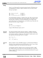
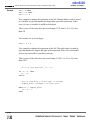
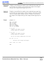
When you declare an array, mikroBasic allocates a certain amount of RAM for it.
Elements of array consume consecutive RAM locations; in case of array of bytes,
if the address of m[0] is 0x23, m[1] will be at 0x24, and so on.
Accessing these elements is almost as fast as accessing any variable of simple
type. Instead of byte you can define array of any other simple type (word, short,
integer or longint). Don't forget that you are restricted by the amount of free space
in PIC RAM memory.
page
32
MikroElektronika: Development tools - Books - Compilers
mikroBASIC
making it simple...
mikroBASIC - Basic Compiler for Microchip PIC microcontrollers
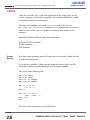
For example:
dim size as longint[10]
occupies 40 RAM locations (bytes).
PIC MCU RAM
m[0]
m[0]
m[0]
m[1]
m[0]
m[0]
m[2]
m[0]
m[3]
Array is just a specified set
of data in memory,
stored in consequent
locations
After you have declared an array,
for example:
dim m as byte[5]
you can easily access its elements
m[0],m[1],m[2]....
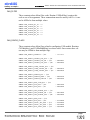
Example
program Array_test
dim weights as byte[10]
dim m as byte[13]
dim j as byte[5]
j[0] = m[3] + 6
m[4] = m[2] mod 3
j[2] = not j[0]
if m[0] > 0 then
m[1] = 9
else
m[1] = 90
end if
end.
page
MikroElektronika: Development tools - Books - Compilers
33
mikroBASIC
mikroBASIC - Basic Compiler for Microchip PIC microcontrollers
making it simple...
Strings
String represents a sequence of characters. String type is similar to array, but can
hold only characters.
dim M_name as string[16]
dim Start_message as string[6]
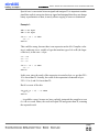
For each string declaration, compiler will reserve the appropriate amount of memory locations. For example, string M_name will take 16+1 locations; additional
memory location is reserved to contain the length of the string. If we assign string
literal to variable M_name, M_name = "mik", then:
M_name[0]
M_name[1]
M_name[2]
M_name[3]
will be 3 (contains length of the string)
will be 'm'
will be 'i'
will be 'k'
and all other locations will be undefined.
Strings and
assignment
Assignment operator can be used with string variables:
dim M
S
main:
M =
S =
end.
Length
as string[20]
as string[8]
"port"
"port1"
' Assign 'port' to M
' Assign 'port1' to S
mikroBasic includes a built-in function Length for working with strings:
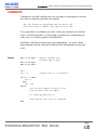
sub function Length(dim text as string) as byte
It returns string length as byte, and is quite useful for handling characters within
string:
M = "mikroElektronika"
for i = 1 to Length(M)
Lcd_Chr(PORTD,1,i,M[i])
next i
page
34
MikroElektronika: Development tools - Books - Compilers
mikroBASIC
making it simple...
mikroBASIC - Basic Compiler for Microchip PIC microcontrollers
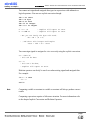
NUMERALS AND CHARACTER STRINGS
Numerals
Numeric constants can be represented in decimal, binary, or hexadecimal number
system.
In decimal notation, they are represented as a sequence of digits, without commas
or spaces, and can be prefixed with + or - operator to indicate the sign. Values
default to positive (67258 is equivalent to +67258).
The dollar-sign prefix or a 0x prefix indicates a hexadecimal numeral (for example
$8F or 0xC9).
The percent-sign indicates a binary numeral (for example %0101).
Example:
123
$1fc
0xb9
%101
Decimal
Hex
Hex
Binary
Character Strings
Character string, also called a string literal or a string constant, consists of a quoted string. Separators can be used only within quoted strings. A quoted string is a
sequence of up to 255 characters from the extended ASCII character set, written in
one line and enclosed by apostrophes.
Quoted string with nothing between the apostrophes is a null string. Apostrophe
itself cannot be used as part of the string. For example:
"mikroBasic"
""
" "
' mikroBasic
' null string
' a space
Length of character string is the number of characters it consists of. Character
string of length 1 is compatible with the char type. You can assign string literal to
a string variable or to array of char.
page
MikroElektronika: Development tools - Books - Compilers
35
mikroBASIC
mikroBASIC - Basic Compiler for Microchip PIC microcontrollers
making it simple...
CONSTANTS
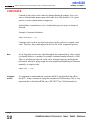
Constant is data whose value cannot be changed during the runtime. Every constant is declared under unique name which must be a valid identifier. It is a good
practice to write constant names in uppercase.
In mikroBasic, constants have to be of simple data type (no arrays or strings are
allowed).
Example of constant declaration:
const MAXVALUE = 237
Constants can be used in any legal expression, but they cannot be assigned a new
value. Therefore, they cannot appear on the left side of the assignment operator.
Note
If you frequently use the same value throughout the program and its value is fixed,
you should declare it a constant (for example, maximum number allowed is 1000).
This is a good practice since the value can be changed simply by modifying the
declaration, instead of going trough the entire program and adjusting each instance
manually. As simple as this:
const MAX = 1000
Constants
and PIC
It is important to understand why constants should be used and how this affects
the MCU. Using a constant in a program consumes no RAM memory. This is very
important due to the limited RAM space (PIC16F877 has 368 locations/bytes).
page
36
MikroElektronika: Development tools - Books - Compilers
mikroBASIC
making it simple...
Examples
mikroBASIC - Basic Compiler for Microchip PIC microcontrollers
const MaxAllowed = 234
const K_a = -32766
const Max = 1000
if teA > Max then teA = teA - 100
teC = teC + Min
' Constants can be used in any expression
Examples of
invalid use
const 7time = 123
' Wrong constant name, it must be
' a valid identifier
const Max = 1123456
' Assigned value exceeds the allowed
' range for integer
Max = A
Max = 123
' You cannot assign new value to a constant,
' compiler will report an error
page
MikroElektronika: Development tools - Books - Compilers
37
mikroBASIC
mikroBASIC - Basic Compiler for Microchip PIC microcontrollers
making it simple...
SYMBOLS
Symbol makes possible to replace expression with a single identifier alias. Use of
symbols increases the reusability and flexibility of code.
BASIC syntax restricts you to single line expressions, allowing shortcuts for constants, simple statements, function calls, etc. Scope of symbol identifier is a whole
source file in which it is declared.
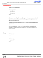
Symbol is declared as:
symbol alias = single_line_expression
where alias must be a valid identifier which you will be using throughout the
code.
Symbols
and PIC
Using a symbol in a program technically consumes no RAM memory - compiler
simply replaces each instance of a symbol with the appropriate code from the declaration.
Example
symbol MaxAllowed = 234
symbol PORT = PORTC
symbol DELAY1S = delay_ms(1000)
' symbol as alias for numeral
' symbol as alias for SFR
' symbol as alias for proc. call
teA > MaxAllowed then
teA = teA - 100
end if
PORT.1 = 0
DELAY1S
...
if
page
38
MikroElektronika: Development tools - Books - Compilers
mikroBASIC
making it simple...
mikroBASIC - Basic Compiler for Microchip PIC microcontrollers
VARIABLES
Variable is data whose value can be changed during the runtime. Every variable is
declared under unique name which must be a valid identifier. This name is used
for accessing the memory location occupied by the variable.
Variable can be seen as a container for data and because it is typed, it instructs the
compiler how to interpret the data it holds. For more details refer to Data Types
and Type Conversion.
For more information on variables' scope refer to the chapter Scope (Variable
Visibility).
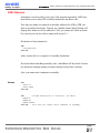
In mikroBasic, variable needs to be declared before it can be used. Specifying a
data type for each variable is mandatory. Basic syntax for variable declaration is:
dim identifier as type
where identifier is any valid identifier, and type can be any valid data type.
For example:
dim tA as byte
dim tB as word
Variables
and PIC
' declare variable tA of byte type
' declare variable tB of word type
Every declared variable consumes part of MCU RAM memory. Data type of variable determines not only the allowed range of values, but also the space variable
occupies in RAM memory. Bear in mind that operations using different types of
variables take different time to be completed. For example:
Variable tA (byte) occupies 1 byte (8 bit) of RAM memory, while variable tB
(word) occupies 2 bytes (16 bit) of RAM memory.
Therefore, tA = tA + tA is faster to execute than tB = tB + tB.
page
MikroElektronika: Development tools - Books - Compilers
39
mikroBASIC
mikroBASIC - Basic Compiler for Microchip PIC microcontrollers
making it simple...
Note
mikroBasic recycles local variable memory space - local variables declared in different functions and procedures share same memory space, if possible.
Additional
info
Variable declaration has to be properly placed to have a correct meaning. Variables
can be declared in a program block or implementation section of a module.
Variable declaration must be placed ahead of the keyword begin. You can also
declare variables in function or procedure block. Refer to Program Organization,
and see the following example.
There is no need to declare PIC SFR (Special Function Registers), as they are
already declared as global variables of byte type - for example: TMR0, PCL, STATUS, PORTA, TRISA, etc. These variables may be used anywhere within the
code.
For closer information on how to use variables and build valid expressions refer to
the chapter Operators.
page
40
MikroElektronika: Development tools - Books - Compilers
mikroBASIC
making it simple...
Examples
mikroBASIC - Basic Compiler for Microchip PIC microcontrollers
program TRIAL
include "other.pbas"
' You can declare variables in the program block
dim
dim
dim
dim
dim
dim
tA
tD
tF
tR
tT
tY
as
as
as
as
as
as
integer
integer
integer
word
word
word
main:
tA = tD and tF
tR = STATUS and $03
TMR0 = 45
end.
...
module other
' You can declare variables at the
' beginning of a module
dim Sss as longint
dim Ddd as longint
...
end.
sub function Sum( dim R as byte) as byte
' You can also declare variables in
' function or procedure block.
dim B as char
dim K as byte
...
end sub
page
MikroElektronika: Development tools - Books - Compilers
41
mikroBASIC
mikroBASIC - Basic Compiler for Microchip PIC microcontrollers
making it simple...
Any valid variable can be used after it has been declared:
tA
'
tC
'
'
= 36
assign new value to the existing variable
= tA + tB
perform any kind of arithmetical or
logical operation
tE = pr_function(1,tA)
' pass variable to function or procedure,
' by value or address
pr_procedure(1,2,tD,tE)
' use them in conditional and/or
' loop statements and more ...
select case tb
case 1
tA = tD + 4
case 2
tB = tC + 6
case 3
tC = $ff
tb = tc - tA
case else
pr_procedure(1,2,tD,tE)
end select
for tA = 0 to 7
tC = tB >> 1
next tA
page
42
MikroElektronika: Development tools - Books - Compilers
mikroBASIC
making it simple...
mikroBASIC - Basic Compiler for Microchip PIC microcontrollers
COMMENTS
Comments are text that is added to the code for purpose of description or clarification, and are completely ignored by the compiler.
' Any text between an apostrophe and the end of the
' line constitutes a comment. May span one line only.
It is a good practice to comment your code, so that you or anybody else can later
re-use it. On the other hand, it is often useful to comment out a troublesome part
of the code, so it could be repaired or modified later.
mikroBasic Code Editor features syntax color highlighting - it is easy to distinguish comments from the code due to different color, and comments are also italicized.
Example
dim teC as byte
' declare variable teC,
' variable type is byte
dim teB as byte
dim teA as byte
main:
teC = 12
' assign value 12 to variable C
if teA > 0 then
teC = 9
else
teA = teB
end if
' you can also comment out part of the
' code you don't want to compile:
' E = gosub pr_function(1,2)
' This function call won't be compiled
end.
page
MikroElektronika: Development tools - Books - Compilers
43
mikroBASIC
mikroBASIC - Basic Compiler for Microchip PIC microcontrollers
making it simple...
EXPRESSIONS
Expression is a construction that returns a value. The simplest expressions are
variables and constants, while more complex expressions are constructed from
simpler ones using operators, function calls, indexes, and typecasts.
Rules for creating legal expressions are presented in chapter Implicit Conversion
and Legal Expressions.
These are all expressions:
X
15
Calc(X, Y)
X * Y
Legal
Expressions
'
'
'
'
variable
integer constant
function call
product of X and Y
We will present in short notice rules for building expressions here. But, we should
recollect some information beforehand:
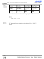
Simple data types include: byte, word, short, integer and longint.
Byte and word types hold only positive values so we’ll call them unsigned.
Ranges are:
byte
word
0 .. 255
0 .. 65535
Short, integer, and longint types can hold both positive and negative numbers so
we’ll call them signed. Ranges are:
short
integer
longint
-128 .. 127
-32768 .. 32767
-2147483648 .. 214748364
page
44
MikroElektronika: Development tools - Books - Compilers
mikroBASIC
making it simple...
mikroBASIC - Basic Compiler for Microchip PIC microcontrollers
You cannot mix signed and unsigned data types in expressions with arithmetic or
logical operators. You can use explicit conversion though.
dim
dim
dim
dim
dim
...
A =
A =
Sa as short
A as byte
Bb as word
Sbb as integer
Scccc as longint
A + Sa
A and Sa
' compiler will report an error
' compiler will report an error
' But you can freely mix byte with word..
Bb = Bb + (A * A)
' ..and short with integer and longint
Scccc = Sbb * Sa + Scccc
You can assign signed to unsigned or vice versa only using the explicit conversion.
Sa = short(A)
' this can be done
Sa = A
' this can't be done,
' compiler will report an error
Relation operators can freely be used even when mixing signed and unsigned data.
For example:
if Sa > B then
Sa = 0
end if
Note
Comparing variable or constant to variable or constant will always produce correct
results.
Comparing expressions requires a little more attention. For more information refer
to the chapter Implicit Conversion and Relation Operators.
page
MikroElektronika: Development tools - Books - Compilers
45
mikroBASIC
mikroBASIC - Basic Compiler for Microchip PIC microcontrollers
making it simple...
DECLARATIONS AND STATEMENTS
Aside from the include clause, program consists entirely of declarations and
statements, which are organized into blocks.
Declarations
Names of variables, constants, types, procedures, functions, programs and units
are called identifiers (numeric constant like 321 is not an identifier).
Identifiers need to be declared before you can use them. Only exceptions are few
predefined types, library functions and procedures, PIC MCU SFR ( PIC Special
Function Registers), and constants; these are understood by the compiler automatically.
Declaration defines an identifier and, where appropriate, allocates memory for it.
For example:
dim Right as word
declares a variable called Right that holds a word value, while:
sub function Each(dim X as integer, dim Y as integer) as integer
declares a function called Each which collects two integers as arguments and
returns an integer.
Each declaration ends with a semicolon (separator). When declaring several variables, constants, or types at the same time, you need to write the appropriate
reserved word only once :
dim Height as integer
dim Description as string[10]
The syntax and placement of a declaration depends on the kind of identifier you
are defining. In general, declarations take place only at the beginning of a block,
or at the beginning of the implementation section of a unit (after the include
clause). Specific conventions for declaring variables, constants, types, functions,
and so forth can be found in the appropriate chapters.
page
46
MikroElektronika: Development tools - Books - Compilers
mikroBASIC
making it simple...
mikroBASIC - Basic Compiler for Microchip PIC microcontrollers
Statements
Statements define algorithmic actions within a program. Simple statements - like
assignments and procedure calls - can be combined to form loops, conditional
statements, and other structured statements. Refer to Implicit Conversion and
Assignment.
Simple Statements
Simple statement does not contain any other statements. Simple statements include
assignments, and calls to procedures and functions.
Structured Statements
Structured statements are constructed from other statements. Use a structured
statement when you want to execute other statements sequentially, conditionally,
or repeatedly.
Conditional statements if and case execute at most one of their constituents,
depending on a specified criteria.
Loop statements repeat, while, and for execute a sequence of constituent statements repeatedly.
MikroElektronika: Development tools - Books - Compilers
47
mikroBASIC
making it simple...
mikroBASIC - Basic Compiler for Microchip PIC microcontrollers
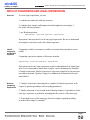
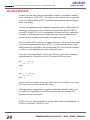
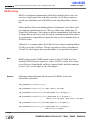
DIRECTIVES
Directives are words of special significance for the mikroBasic, but unlike other
reserved words, appear only in contexts where user-defined identifiers cannot
occur.
You cannot define an identifier that looks exactly like a directive.
Overview
Directive
Meaning
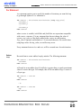
absolute
Specifies the exact location of variable in RAM
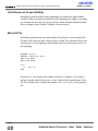
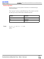
Absolute directive specifies the starting address in RAM for variable (if variable is
multi-byte, higher bytes are stored at consecutive locations).
Directive absolute is appended to the declaration of variable:
dim rem as byte absolute $22
' Variable will occupy 1 byte at address $22
dim dot as word absolute $23
' Variable will occupy 2 bytes at addresses $23 and $24
PIC MCU RAM
m[0]
Byte variable will occupy
1 byte at address $22
Word variable will occupy
2 bytes
At addresses $23 and $24
page
48
MikroElektronika: Development tools - Books - Compilers
mikroBASIC
making it simple...
Important
mikroBASIC - Basic Compiler for Microchip PIC microcontrollers
We recommend careful use of absolute directive, because you may overlap two
variables by mistake. For example:
dim Ndot as byte absolute $33
' Variable will occupy 1 byte at address $33
dim Nrem as longint absolute $30
' Variable will occupy 4 bytes at $30, $31, $32, $33,
' so changing Ndot changes Nrem highest
' byte at the same time
Runtime
Behavior
mikroBasic uses internal algorithm to distribute variables within RAM. If there is
a need to have variable at specific predefined address, use the directive absolute.
Also if, for some reason, you want to overlap existing variables, use the directive
absolute.
Example
program lite
' example for P16F877A
dim image_trisa as byte absolute 133
main:
image_trisa = $ff
end.
page
MikroElektronika: Development tools - Books - Compilers
49
mikroBASIC
mikroBASIC - Basic Compiler for Microchip PIC microcontrollers
making it simple...
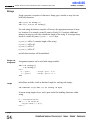
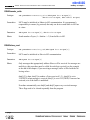
PROCEDURES AND FUNCTIONS
Procedures and functions, collectively referred to as routines, are self-contained
statement blocks that can be called from different locations in a program. Function
is a routine that returns a value when it is executed. Procedure is a routine that
does not return a value.
Once these routines have been defined, you can call them once or multiple times.
Procedure is called upon to perform a certain task, while function is called to compute a certain value. Function calls, because they return a value, can be used as
expressions in assignments and operations.
Procedures
Procedure declaration has the form:
sub procedure procedureName(parameterList)
localDeclarations
statements
end sub
where procedureName is any valid identifier, statements is a sequence of statements that are executed upon the calling the procedure, and (parameterList) and
localDeclarations are optional declaration of variables and/or constants.
sub procedure pr1_procedure(dim par1 as byte, dim par2 as byte,
dim byref vp1 as byte, dim byref vp2 as byte)
dim locS as byte
par1 = locS + par1 + par2
vp1 = par1 or par2
vp2 = locS xor par1
end sub
par1 and par2 are passed to the procedure by the value, but variables marked by
keyword byref are passed by the address.
page
50
MikroElektronika: Development tools - Books - Compilers
mikroBASIC
making it simple...
mikroBASIC - Basic Compiler for Microchip PIC microcontrollers
This means that the procedure call
pr1_procedure(tA, tB, tC, tD)
passes tA and tB by the value: it first creates par1 = tA and par2 = tB, then manipulates par1 and par2 so that tA and tB remain unchanged;
passes tC and tD by the address: whatever changes are made upon vp1 and vp2
are also made upon tC and tD.
Note that a procedure without parameters can be substituted by label which marks
the beginning of “procedure” and keyword return that marks the end of “procedure”. To call such subroutine, use the keyword gosub. These subroutines must be
placed between the label main: and the end of the source file.
main:
if PORTC.1 = 1 then
gosub TogglePortb
end if
...
' some code
TogglePortb:
' routine
portb = not portb
return
end.
Functions
Function declaration is similar to procedure declaration, except it has a specified
return type and a return value. Function declaration has the form:
sub function functionName(parameterList) as returnType
localDeclarations
statements
end sub
where functionName is any valid identifier, returnType is any simple type, statements is a sequence of statements to be executed upon calling the function, and
(parameterList) and localDeclarations are optional declarations of variables
and/or constants.
page
MikroElektronika: Development tools - Books - Compilers
51
mikroBASIC
mikroBASIC - Basic Compiler for Microchip PIC microcontrollers
making it simple...
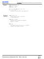
In mikroBasic, use the keyword Result to assign the return value of a function.
Example:
sub function pr6_function(dim par1 as byte, dim par2 as word) as word
dim locS as word
locS = par1 + par2
Result = locS
end sub
Function Calls
As functions return a value, function calls are technically expressions. For example, if you have defined a function called Calc, which collects two integer arguments and returns an integer, then the function call Calc(24, 47) is an integer
expression. If I and J are integer variables, then I + Calc(J, 8) is also an integer expression. Here are a few examples of function calls:
Sum(tA,63)
Maximum(147,J)
GetValue
Important
Note that cross-calling and recursive calls are not allowed in mikroBasic. Crosscalling is an instance of procedure A calling procedure B, and then procedure B
calling procedure A. Recursive call is an instance of procedure or function calling
itself. Compiler will report error if cross-calling or recursive calls are encountered
in the code.
mikroBasic has a number of built-in and predefined library routines. For example,
procedure interrupt is the interrupt service routine.
Nested calls are limited to 8-level depth for PIC16 series and 31-level depth for
PIC18 series. Nested call represent call of another function or procedure within a
function or procedure. For closer information, refer to the chapter PIC Specifics.
page
52
MikroElektronika: Development tools - Books - Compilers
mikroBASIC
making it simple...
mikroBASIC - Basic Compiler for Microchip PIC microcontrollers
Procedure or
Function
Procedure or
Function
Nested procedures
or functions calls
are limited to 8
for PIC16 series,
and to 31 for PIC18
Number of allowed
nested calls will be
decremented by 1 if
you use interrupt
procedure and 1 more
if you use *, div, mod
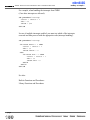
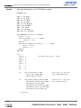
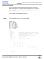
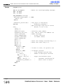
Example
sub function mask(dim byref
'
select case num
'
case 0 result = $3F
'
case 1 result = $06
case 2 result = $5B
'
case 3 result = $4F
case 4 result = $66
case 5 result = $6D
case 6 result = $7D
case 7 result = $07
case 8 result = $7F
case 9 result = $6f
'
end select
end sub
Procedure or
Function
Compiler will report
stack overflow error
if you exceed the
allowed number of
nested calls
num as byte) as byte
This function returns code for digit
for common cathode 7 seg. display.
Note that the value of result is not
initialized for values greater than 9
case end
MikroElektronika: Development tools - Books - Compilers
53
mikroBASIC
mikroBASIC - Basic Compiler for Microchip PIC microcontrollers
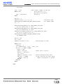
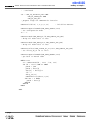
Example of
Stack
Overflow
making it simple...
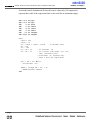
sub program Stack_overflow
sub procedure interrupt
nop
end sub
sub procedure proc0
nop
end sub
sub procedure proc1
proc0
end sub
sub procedure proc2
proc1
end sub
sub procedure proc3
proc2
end sub
sub procedure proc4
proc3
end sub
sub procedure proc5
proc4
end sub
sub procedure proc6
proc5
end sub
sub procedure proc7
proc6
end sub
main:
proc7
end.
page
54
MikroElektronika: Development tools - Books - Compilers
mikroBASIC
making it simple...
mikroBASIC - Basic Compiler for Microchip PIC microcontrollers
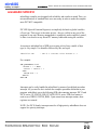
MODULES
Each project consists of a single project file, and one or more module files. To
build a project, the compiler needs either a source file or a compiled file for each
module.
Project
file
Module
files
Every project consist of single project file and
one or more module files
Each module is stored in its own file and compiled separately; compiled modules
are linked to create an application.
Modules allow you to:
-
Break large programs into parts that can be edited separately.
-
Create libraries that can be used in different programs.
-
Distribute libraries to other developers without disclosing the source code.
In mikroBasic programming, all source code including the main program is stored
in .pbas files.
If you perform circular unit references, compiler will give a warning. A simple
instance of circular unit references would be, for example, situation in which
Module1 uses Module2, but in the same time it is specified that Module2 uses
Module1.
Newly created blank unit contains the following :
module Module1
end.
page
MikroElektronika: Development tools - Books - Compilers
55
mikroBASIC
mikroBASIC - Basic Compiler for Microchip PIC microcontrollers
making it simple...
Unit Influence on Scope (Visibility)
mikroBasic variables defined at the beginning of the module are global hidden
variables. When you declare an identifier at the beginning of a module, you cannot
use it outside the unit, but you can use it in any routine defined within the module.
Refer to chapter Scope (Variable Visibility) for more details.
Main Unit File
mikroBasic application has one main module file and none or more module files.
All source files have the same extension (pbas). Main file is identified by the keyword program at the beginning; other module files have the keyword module at
the beginning.
program Project1
include "additional.pbas"
dim tA as word
dim tB as word
main:
tA = sqrt(tb)
end.
Keyword include instructs the compiler which file to compile. If you want to
include a module, add the keyword include followed by the quoted name of the
file. The example above includes the module additional.pbas in the program
file.
page
56
MikroElektronika: Development tools - Books - Compilers
mikroBASIC
making it simple...
mikroBASIC - Basic Compiler for Microchip PIC microcontrollers
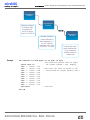
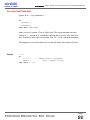
Module
files
Project
file
mikroBasic
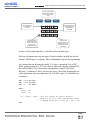
1.
Once you have
written your
program,
mikroBasic
can compile
each unit file
and create mcl
files
Compiler
mcl files
Def file
2.
Linker
mikroBasic
links mcl files
and creates
asm, list and
hex files
Library
mcl files
Output Generator
Output
Generator
HEX file
LST file
ASM file
3.
Finally, you can
load hex file to
programmer
and program
the device
Programmer
PIC MCU
page
MikroElektronika: Development tools - Books - Compilers
57
mikroBASIC
mikroBASIC - Basic Compiler for Microchip PIC microcontrollers
making it simple...
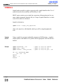
SCOPE (IDENTIFIER VISIBILITY)
Scope, or identifier visibility, determines if identifier can be referenced in certain
part of the program code. Location of identifier declaration in the code determines
its scope. Identifiers with narrower scope - especially identifiers declared in functions and procedures - are sometimes called local, while identifiers with wider
scope are called global.
All functions and procedures are visible in the whole project, and they are visible
in any part of the program or any module. Constants not local for a procedure or
function are also visible in the whole project. Local constants are visible only in
procedure or function body in which they are declared.
Rules for determining the variable identifier scope are summarized below:
-
If the identifier is declared in the declaration of a main module, it is
visible from the point where it is declared to the end of the module.
-
If the identifier is declared in the declaration of function, or procedure, its
scope extends from the point where it is declared to the end of the current
block, including all blocks enclosed within that scope.
-
If the identifier is declared in the implementation section of a module, but
not within the block of any function or procedure, its scope extends from
the point where it is declared to the end of the module. The identifier is
available to any function or procedure in the module.
PIC SFR (Special Function Registers), are implicitly declared as global variables
of byte type. Their scope is the entire project and they are visible in any part of the
program or any module.
page
58
MikroElektronika: Development tools - Books - Compilers
mikroBASIC
making it simple...
mikroBASIC - Basic Compiler for Microchip PIC microcontrollers
For example, in a function declaration:
sub function Com(dim R as byte) as byte
dim B as char
dim K as byte
...
end sub
first line of the declaration is the function heading . B and K are local variables;
their declarations apply only to the Com function block and override - in this routine only - any declarations of the same identifiers that may occur in the program
module or at beginning of a module.
page
MikroElektronika: Development tools - Books - Compilers
59
mikroBASIC
mikroBASIC - Basic Compiler for Microchip PIC microcontrollers
making it simple...
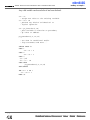
PROGRAM ORGANIZATION
Program elements (constants, variables and routines) need to be declared in their
proper place in the code. Otherwise, compiler may not be able to comprehend the
program correctly.
Organization of the main unit should have the following form:
program program_name
include ...
' program name
' include other units
symbol ...
const ...
dim ...
' symbols declaration
' constants declaration
' variables declaration
sub procedure procedure_name
...
end sub
' procedures declaration
sub function function_name
...
end sub
' functions declaration
main:
' program must start with label
' main
...
end.
' program body
' end of program
page
60
MikroElektronika: Development tools - Books - Compilers
mikroBASIC
making it simple...
mikroBASIC - Basic Compiler for Microchip PIC microcontrollers
Organization of other modules should have the following form:
module unit_name
include ...
' unit name
' include other units
symbol ...
const ...
dim ...
' symbols declaration
' constants declaration
' variables declaration
sub procedure procedure_name
...
end sub
' procedures declaration
sub function function_name
...
end sub
' functions declaration
end.
' end of module
page
MikroElektronika: Development tools - Books - Compilers
61
mikroBASIC
mikroBASIC - Basic Compiler for Microchip PIC microcontrollers
making it simple...
TYPE CONVERSION
mikroBasic is capable of both implicit and explicit conversion of data types.
Implicit conversion is the one automatically performed by compiler. On the other
hand, explicit conversion is performed only on demand issued by user.
This means that you can, obeying a few rules, combine simple data types with any
operators to create legal expressions and statements. Refer to Data Types if you
are not familiar with data types supported by mikroBasic.
As stated in the chapter about operators, you cannot mix signed and unsigned data
types in expressions that contain arithmetic or logical operators. You can assign
signed to unsigned or vice versa only using the explicit conversion.
Implicit Conversion
-
Implicit conversion takes place between byte and word, so you can combine byte and word with any operators to form legal expressions.
-
Implicit conversion takes place between short, integer and longint so you
can combine short, integer and longint with any operators to form legal
expressions.
-
Relation operators can be used without any restraints. Smart algorithm
governing relation operators allows comparing any two data types.
-
The compiler provides automatic type conversion when an assignment is
performed, but does not allow to assign signed data type to unsigned and
vice versa.
You can find more information on implicit conversion in chapters Assignment and
Implicit Conversion, and Implicit Conversion and Legal Expressions.
Explicit Conversion
Explicit conversion can be executed at any point by inserting type (byte, word,
short, integer, or longint) ahead of the expression to be converted. The expression
must be enclosed in parentheses. You can't execute explicit conversion on the
operand left of the assignment operator.
page
62
MikroElektronika: Development tools - Books - Compilers
mikroBASIC
making it simple...
mikroBASIC - Basic Compiler for Microchip PIC microcontrollers
Special case is conversion between signed and unsigned. It is important to understand that explicit conversion between signed and unsigned data does not change
binary representation of data; it merely allows copying of source to destination.
Example 1:
dim tA as byte
dim tB as byte
if tA + tB > tC then
tA = 0
end if
This could be wrong, because there is an expression on the left. Compiler evaluates it, and treats it as a variable of type that matches type of tA or tB (the larger
of the two); in this case - a byte.
tA = 250
tB = 10
tC = 20
if tA + tB > tC then
tA = 0
end if
In this case, since the result of the expression is treated as byte, we get that 250 +
10 is lower than 20. Actually, the result of the expression is truncated to byte:
250 + 10 is 4, and 4 is lower than 20.
But if we wrote it like this:
if word(tA + tB) > tC then
tA = 0
end if
. . it would be correct, because we have explicitly instructed the compiler to treat
tA + tB as a word. Hence, the result will equal 260 and greater than 20, returning
the expected result.
page
MikroElektronika: Development tools - Books - Compilers
63
mikroBASIC
mikroBASIC - Basic Compiler for Microchip PIC microcontrollers
making it simple...
Example 2:
Explicit conversion can also be used when you are sure which type you want to
convert expression to. Consider the following lines:
dim
dim
dim
dim
dim
tA
tB
tC
A_
B_
as
as
as
as
as
byte
byte
byte
short
short
tA = byte(A_)
B_ = short(tA + tB * tC)
It is important to understand that explicit conversion between signed and unsigned
data does not change binary representation of data; it only allows copying source
to destination. Thus, if A_ was -1, its binary representation would be 11111111,
and A would become 255.
Even if you have ordered the explicit conversion, compiler will perform implicit if
necessary.
Example 3:
You cannot execute explicit conversion on the operand left of the assignment operator:
word(b) = Bb
' compiler will report an error.
page
64
MikroElektronika: Development tools - Books - Compilers
mikroBASIC
making it simple...
mikroBASIC - Basic Compiler for Microchip PIC microcontrollers
ASSIGNMENT AND IMPLICIT CONVERSION
Overview
mikroBasic provides automatic type conversion every time an assignment is performed. But it does not allow assigning signed data to unsigned and vice versa,
because there is a significant risk of losing information.
Implicit conversion takes place when assignment is performed:
between byte and word
between short, integer, and longint
Notes
Destination will store the correct value only if it can properly represent the result
of expression (that is, if the result fits in destination range).
Feel free to use operands of any size under the defined rules, but keep in mind that
the PIC is optimized to work with bytes. Every operation involving more complex
data types (word, integer or longint) will take more run time and more memory. So
for the best possible results, use as small destinations and operands as you can.
Examples
A = B
If A and B are of the same type, value of B is simply assigned to A. More interesting case is if A and B are of different types:
dim
dim
...
B =
A =
A as byte
B as word
0xff0f
B
' A becomes $0f, higher byte $ff is lost
If A is more complex than B, then B is extended to fit the correct result:
dim
dim
...
A =
B =
A as word
B as byte
0xff
A
' B becomes $00ff
page
MikroElektronika: Development tools - Books - Compilers
65
mikroBASIC
mikroBASIC - Basic Compiler for Microchip PIC microcontrollers
making it simple...
For signed types :
dim
dim
...
A_
B_
B_ as integer
A_ as short
= -10
= A_
' B becomes -10
In hex representation, this means that the higher byte is sign extended.
C = expression
Calculated value of the expression will be assigned to the destination. Part of the
information may be lost if the destination cannot properly represent the result of
the expression (i.e. if result can't fit in range of destination data type). Browse
through examples for more details.
For example (this is correct):
C = A + B
C is byte, so its range is 0 .. 255. If (A + B) fits in this range you will get the correct value in C.
A = 123
B = 90
C = A + B
' C becomes 213
But what happens when A + B exceeds the destination range? Let's assume the
following:
A = 241
B = 128
C = A + B ' C becomes 113, obviously incorrect
See the following figure for closer explanation.
page
66
MikroElektronika: Development tools - Books - Compilers
mikroBASIC
making it simple...
mikroBASIC - Basic Compiler for Microchip PIC microcontrollers
Lets see what happens
when we add two bytes
and assign result to
byte
byte3
First byte has value
241 and its binary
representation is
11110001
=
byte2
+
byte1
1 1 1 1 0 0 0 1
+
1 0 0 0 0 0 0 0
Second byte has value
128 and its binary
representation is
10000000
=
1
0 1 1 1 0 0 0 1
Result has 9 bits.
Because destination
byte can hold only 8
bits, the most
significant bit is lost
As byte3 holds
01110001, result is 113
instead of 369. Most
significant bit is lost:
(1)01110001
In order to fully understand this, we should recollect the data types.
Data type determines not only the range of values variable can hold, but also the
amount of RAM space it consumes. This is fundamental in practical programming.
Let's assume that our destination variable C is a byte, consuming 8 bits of PIC
RAM, spanning values 0 to 255. Now observe what really happens inside the PIC:
the result should be 369, but in binary representation it equals (1)01110001.
Because C is limited to 8 bits it will store the lower 8 bits while dropping the rest
of the information (the most significant bit). 01110001 equals 113 in decimal representation.
dim
dim
dim
testA as byte
testB as byte
Cc
as word
main:
testA = 250
testB = 10
Cc = testA + testB ' this will always be correct because
' range for Cc is 0..65535 and maximum result
' of adding two bytes is only 255 + 255 = 510
end.
page
MikroElektronika: Development tools - Books - Compilers
67
mikroBASIC
mikroBASIC - Basic Compiler for Microchip PIC microcontrollers
making it simple...
As already stated, destination will store the correct value only if it can properly
represent the result of the expression (that is, the result fits in destination range).
dim testA as byte
dim testB as byte
dim
Cc as word
dim
Sa as short
dim
Sb as short
dim
Sc as short
dim
Saa as integer
dim Sbbbb as longint
main:
testA = 250
testB = 10
' Cc becomes 2510;
Cc = testA * testB + testB
Sb = 120
Sc = -100
' Sa becomes 20;
Sa = Sb + Sc
Sa = Sb - Sc
' Sa is short with range -127..128,
' thus, instead of 220,
' Sa becomes -36, because only
' lower 8 bits are registered
Saa = (Sb * Sc) div 13
' Saa becomes -923
Sbbbb = integer(Sb * Sc) * Sc
' Sbbbb becomes 1200000
end.
page
68
MikroElektronika: Development tools - Books - Compilers
mikroBASIC
making it simple...
mikroBASIC - Basic Compiler for Microchip PIC microcontrollers
IMPLICIT CONVERSION AND LEGAL EXPRESSIONS
Overview
To create legal expressions, you can:
1. combine byte and word with any operators,
2. combine short, integer, and longint (note that longint does not employ *,
div, mod) with any operators,
3. use Relation operators
expression1 (relation operator) expression2
Expression1 and expression2 can be any legal expressions. Be sure to understand
how implicit conversion works with relation operators.
Implicit
Conversion
and Relation
Operators
Comparing variable or constant to variable or constant always produces correct
results.
Comparing expressions requires a little more attention.
expression1 (relation operator) expression2
Expressions can be any legal expressions created with arithmetical or logical operators. Every expression no matter how complex, can be decomposed to a number
of simple expressions. Simple expression is expression composed of just one operator and its operands. Operator is logical or arithmetical. Examine the rules presented below.
Rules for
Comparing
Expressions
1. Complex expression is decomposed to a number of simple expressions, with
respect to operator precedence and overriding parenthesis.
2. Simple expression is now treated in the following manner: if operands are of the
same type, operation is performed, assuming that the result is of the same type.
3. If operands are not of the same type, then less complex operand (speaking
in terms of data range) is extended:
page
MikroElektronika: Development tools - Books - Compilers
69
mikroBASIC
mikroBASIC - Basic Compiler for Microchip PIC microcontrollers
making it simple...
-
If one operand is byte and another is word, byte is converted in
word.
-
If one operand is short and another is integer, short is converted to
integer.
-
If one operand is short and another is longint, short is converted to
longint.
-
If one operand is integer and another is longint, integer is converted to
longint.
4. After the first expression is decomposed to simpler ones, each of these simpler
ones is evaluated abiding the rules presented here.
Expression a + b + c is decomposed like this:
First evaluate a + b and get (value of a + b)
This gives us another simple expression
(value of a + b) + c
Let's assume a and b are bytes and c is word, with values:
a = 23
b = 34
c = 1000
Compiler first calculates value of a + b and assumes that the result is byte:
a + b gives 57.
As c is of word type, result of adding a + b is casted to word and then added to c:
57 + c is 1057.
Signed and unsigned numbers cannot be combined using arithmetical and logical
operators. Rules presented above are not valid when assigning expression result to
variable.
page
70
MikroElektronika: Development tools - Books - Compilers
mikroBASIC
making it simple...
mikroBASIC - Basic Compiler for Microchip PIC microcontrollers
r = expression
Refer to chapter Assignment and Implicit Conversion for details.
Note
When adding operands of the same type and assigning value to third operand,
incorrect value may be proceeded if the result exceeds range of declared data type.
Similar rules apply to other arithmetical operators.
For example, if a and b are bytes, and cc is word:
a = 56
b = 200
cc = 1000
a + b equals 1, because result type is assumed to be same as the operands' type
(byte).
Added to cc, we get 1001, instead of the expected 1256.
Solution is to simply instruct the compiler to evaluate expression as you explicitly
define. For example, you could explicitly cast the expression, like this: word(a +
b + c). As result fits in word range, we will get 1256 as we wanted to.
For more details, refer to chapter Explicit Conversion.
Comparing variables and constants always produces the correct results regardless
of the operands' type.
page
MikroElektronika: Development tools - Books - Compilers
71
mikroBASIC
mikroBASIC - Basic Compiler for Microchip PIC microcontrollers
Example
making it simple...
if A > B then ...
if A > 47 then ...
if A + B > A ...
First, compiler evaluates the expression on the left. During runtime, result is stored
in a variable of type that matches the largest data type in the expression. In this
case it is byte, as variables A and B are both bytes.
This is correct if the value does not exceed range 0..255, that is, if A + B is less
than 255.
Let's assume Aa is of word type :
if Aa + B > A ...
First, compiler evaluates the expression on the left. The result value is treated as
type that matches the largest data type in the expression. Since Aa is word and B
is byte, our result will be treated as word type.
This is correct if the value does not exceed range 0..65535, i.e. if Aa + B is less
than 65535.
' if tC is less than zero, tC = -tC
tC < 0
tC = -tC
end if
if
then
' Stay in loop while C is not equal to variable
' compare_match; increment C in every cycle
while tC <> compare_match
tC = tC + 1
wend
page
72
MikroElektronika: Development tools - Books - Compilers
mikroBASIC
making it simple...
mikroBASIC - Basic Compiler for Microchip PIC microcontrollers
OPERATORS
There are three types of operators in mikroPascal:
Arithmetic Operators
Logical (Bitwise) Operators
Relation Operators (Comparison Operators)
Operator Precedence
Operator
Priority
not
first (highest)
*, div, mod, and, shl, shr
second
+, -, or, xor
third
=, <>, <, >, <=, >=
fourth (lowest)
In complex expressions, operators with higher precedence are evaluated before the
operators with lower precedence; operators of equal precedence are evaluated
according to their position in the expression starting from the left.
Example 1:
B and T + A
' (bitwise and) B and T, then add A to the result;
' and is performed first, because it has precedence over +.
Example 2:
A - B + D
' first subtract B from A, then add D to the result;
' - and + have the equal precedence, thus the operation on
' the left is performed first.
Example 3:
' You can use parentheses to override these precedence rules.
' An expression within parentheses is evaluated first, then
' treated as a single operand. For example:
(A + B) * D
' multiply D and the sum of A and B.
A + B * D
' first multiply B and D and then add A to the product.
page
MikroElektronika: Development tools - Books - Compilers
73
mikroBASIC
mikroBASIC - Basic Compiler for Microchip PIC microcontrollers
making it simple...
Rules for Creating Legal Expressions
You cannot mix signed and unsigned data types in expressions with arithmetic or
logical operators. If you need to combine signed with unsigned, you will have to
use explicit conversion.
Example:
dim Sa as short
dim teA as byte
dim Bb as word
dim Sbb as integer
dim Scccc as longint
...
' compiler will report an error
teA = teA + Sa
teA = teA and Sa
' compiler will report an error
' But you can freely mix byte and word . .
Bb = Bb + (teA * teA)
' . . and short with integer and longint;
Scccc = Sbb * Sa + Scccc
You can assign signed to unsigned, or unsigned to signed only using the explicit
conversion. More details can be found in chapter Implicit Conversion and
Assignment Operator.
Sa = short(teA)
' this can be done
Sa = A
' this can't be done, compiler will report an error
Relation operators can be used with all data types, regardless of the sign.
Example:
if Sa > teA then
Sa = 0
end if
page
74
MikroElektronika: Development tools - Books - Compilers
mikroBASIC
making it simple...
mikroBASIC - Basic Compiler for Microchip PIC microcontrollers
Notes for Relation Operators
Comparing variable or constant to variable or constant will always produce correct
results.
Comparing expressions requires a little more attention - when compiler is calculating value of the expression to be compared, it first has to evaluate the expression.
If the result of the expression exceeds the range of the largest data type in the
expression, comparison will most likely be inaccurate. This can be avoided by
using the explicit conversion.
More details can be found in chapter Implicit Conversion and Relation Operators.
Runtime Behavior
PIC MCUs are optimized for working with bytes. It takes less time to add two
bytes than to add two words, naturally, and similar pattern is followed by all the
other operators. It is a good practice to use byte or short data type whenever
appropriate. Although the improvement may seem insignificant, it could prove
valuable for applications which impose execution within time boundaries.
This is a recommendation which shouldn't be followed too literally - word, integer
and longint are indispensable in certain situations.
page
MikroElektronika: Development tools - Books - Compilers
75
mikroBASIC
mikroBASIC - Basic Compiler for Microchip PIC microcontrollers
making it simple...
Arithmetic Operators
Overview
Mod and Div
Operator
Operation
Operand Types
Result Type
+
addition
byte, short, integer, byte, short, integer,
word, longint
word, longint
-
subtraction
byte, short, integer, byte, short, integer,
word, longint
word, longint
*
multiplication
byte, short, integer, integer, word,
word
longint
div
division
byte, short, integer, byte, short, integer,
word
word
mod
remainder
byte, short, integer, byte, short, integer,
word
word
A div B is the value of A divided by B rounded down to the nearest integer. The
mod operator returns the remainder obtained by dividing its operands. In other
words,
X mod Y = X – (X div Y) * Y.
If 0 (zero) is used explicitly as the second operand (i.e. X div 0), compiler will
report an error and will not generate code. But in case of implicit division by zero:
X div Y , where Y is 0 (zero), result will be the maximum value for the appropriate type (for example, if X and Y are words, the result will be $ffff).
Important
Destination will store the correct value only if it can properly represent the result
of the expression (that is, if result fits in the destination range). More details can
be found in chapter Assignment and Implicit Conversion.
Arithmetics
and Data
Types
mikroBasic is more flexible compared to standard Basic as it allows both implicit
and explicit type conversion. In mikroBasic, operator can take operands of different type; refer to chapter Type Conversion for more details. You cannot combine
signed and unsigned data types in expressions with arithmetic operators.
page
76
MikroElektronika: Development tools - Books - Compilers
mikroBASIC
making it simple...
mikroBASIC - Basic Compiler for Microchip PIC microcontrollers
Unsigned and
Conversion
If number is converted from less complex to more complex data type, upper bytes
are filled with zeros. If number is converted from more complex to less complex
data type, data is simply truncated (upper bytes are lost).
Signed and
Conversion
If number is converted from less complex to more complex data type, upper bytes
are filled with ones if sign bit equals 1 (number is negative). Upper bytes are filled
with zeros if sign bit equals 0 (number is positive). If number is converted from
more complex to less complex data type, data is simply truncated (upper bytes are
lost).
Example
program extr
dim
dim
dim
dim
dim
Sa as short
A as byte
Bb as word
Sbb as integer
Scccc as longint
A = A + Sa
' compiler will report an error,
' mixing signed with unsigned;
A = A - Sa
' compiler will report an error,
' mixing signed with unsigned;
' But you can freely combine byte with word . .
Bb = Bb + (A * A)
' . . and short with integer and longint
Scccc = Sbb * Sa + Scccc
end.
page
MikroElektronika: Development tools - Books - Compilers
77
mikroBASIC
making it simple...
mikroBASIC - Basic Compiler for Microchip PIC microcontrollers
Unary
arithmetic
operators
Operator
Operation
Operand Types
Result Types
+(unary)
sign identity
short, integer,
longint
short, integer,
longint
- (unary)
sign negation
short, integer,
longint
short, integer,
longint
Unary arithmetic operators can be used to change sign of variables:
a = 3
b = -a
' assign value -3 to b
Runtime
Behavior
PIC microcontrollers are optimized to work with bytes. Refer to PIC MCU
Specific.
page
78
MikroElektronika: Development tools - Books - Compilers
mikroBASIC
making it simple...
mikroBASIC - Basic Compiler for Microchip PIC microcontrollers
Boolean Operators
Boolean operators are not true operators, because there is no boolean data type
defined in mikroBasic.
These "operators" conform to standard Boolean logic. They cannot be used with
any data type, but only to build complex conditional expression.
Example
Operator
Operation
not
negation
and
conjunction
or
disjunction
if (astr > 10) and (astr < 20) then
PORTB = 0xff
end if
page
MikroElektronika: Development tools - Books - Compilers
79
mikroBASIC
mikroBASIC - Basic Compiler for Microchip PIC microcontrollers
making it simple...
Logical (Bitwise) Operators
Overview
Operator
Operation
not
bitwise negation
and
or
xor
<<
>>
<< and >>
Operand Types
byte, word, short,
integer, long
byte, word, short,
bitwise conjunction
integer, long
byte, word, short,
bitwise disjunction
integer, long
byte, word, short,
bitwise xor
integer, long
byte, word, short,
bit shift left
integer, long
byte, word, short,
bit shift right
integer, long
Result Types
byte, word, short,
integer, long
byte, word, short,
integer, long
byte, word, short,
integer, long
byte, word, short,
integer, long
byte, word, short,
integer, long
byte, word, short,
integer, long
<< : shift left the operand for a number of bit places specified in the right operand
(must be positive and less then 255).
>> : shift right the operand for a number of bit places specified in the right
operand (must be positive and less then 255).
For example, if you need to extract the higher byte, you can do it like this:
dim temp as word
main:
TRISA = word(temp >> 8)
end.
Important
Destination will hold the correct value if it can properly represent the result of the
expression (that is, if result fits in destination range). More details can be found in
chapters Type Conversions and Assignment and implicit Conversion.
Logical
Operators
and Data
Types
mikroBasic is more flexible compared to standard Basic as it allows both implicit
and explicit type conversion. Note that you cannot mix signed and unsigned data
types in expressions with logical operators.
page
80
MikroElektronika: Development tools - Books - Compilers
mikroBASIC
making it simple...
Unsigned and
Conversion
mikroBASIC - Basic Compiler for Microchip PIC microcontrollers
If number is converted from less complex to more complex data type, upper byte
is filled with zeros;
If number is converted from more complex to less complex data type, data is simply truncated (upper bytes are lost).
Example for unsigned and logical operators :
dim
dim
teA as byte
Bb as word
main:
Bb = $F0F0
teA = $aa
Bb = Bb and teA
end.
' Bb becomes $00a0
In this case, A is treated as a word with upper byte equal to 0 prior to the operation.
Signed and
Conversion
If number is converted from less complex data type to more complex, upper bytes
are filled with ones if sign bit is 1 (number is negative); upper bytes are filled with
zeros if sign bit is 0 (number is positive).
If number is converted from more complex data type to less complex, data is simply truncated (upper bytes are lost).
dim
dim
Sa as short
Sbb as integer
main:
Sbb = $70FF
Sa = -12
Sbb = Sbb and Sa
end.
' Bb becomes $70f4
In this case, Sa is treated as an integer with the upper byte equal to $FF (this in
fact is sign extending of short to integer) prior to the operation.
page
MikroElektronika: Development tools - Books - Compilers
81
mikroBASIC
mikroBASIC - Basic Compiler for Microchip PIC microcontrollers
main:
Sbb = $OFF0
Saa = $0a
Sbb = Sbb and Sa
end.
making it simple...
' Bb becomes $0000
In this case, Sa is treated as an integer with the upper byte equal to $00 (this in
fact is sign extending of short to integer) prior to the operation.
Example
dim teA as byte
dim teB as byte
dim teC as byte
' The logical operators perform bitwise manipulation
'
on the operands. For example, if the value stored in
'
teA (in binary) is 00001111 and the value stored in
'
teB is 10000001, the following statements..
main:
teA = $0F
teB = $81
' .. assign the value 00001111 to teA.
' .. assign the value 10000001 to teB.
teC = teA or teB
' Performs bitwise or with teA, teB and the
'
result is assigned to teC (value 10001111)
teC = not teA
' Performs bitwise not with teA and the
'
result is assigned to teC (value 11110000)
teC = teA << 4
' shift teA to the left for a number of positions
'
specified in the operand on the right;
'
operand on the right must be positive.
'
In this example teC becomes $F0
' All bits shifted in are zeros.
teC = teA >> 4
' shift teA to the right for a number of positions
' specified in operand on the right;
' operand on the right must be positive.
' In this example C becomes $00.
' New bits shifted in are zeros if operand type is
' byte/word sign extended for short, word, integer.
end.
page
82
MikroElektronika: Development tools - Books - Compilers
mikroBASIC
making it simple...
mikroBASIC - Basic Compiler for Microchip PIC microcontrollers
' You cannot mix signed and unsigned data types in
' expressions with logical operators:
dim
dim
dim
dim
dim
Sa as short
teA as byte
Bb as word
Sbb as integer
Scccc as longint
main:
teA = teA + Sa
teA = teA and Sa
' compiler will report an error
' compiler will report an error
' But you can freely mix byte with word . .
Bb = Bb and ( not teA)
' . . and short with integer and longint.
Scccc = Sbb xor Sa or Scccc
end.
Runtime
Behavior
PIC microcontrollers are optimized to work with bytes. Refer to PIC MCU
Specific.
page
MikroElektronika: Development tools - Books - Compilers
83
mikroBASIC
mikroBASIC - Basic Compiler for Microchip PIC microcontrollers
making it simple...
Relation (Comparison) Operators
Overview
Operator
Operation
Operand Types
Result Types
=
equality
All simple types
True or False
<>
inequality
All simple types
True or False
<
less-than
All simple types
True or False
>
greater-than
All simple types
True or False
<=
less-than-or-equal All simple types
True or False
>=
greater-than-orequal
True or False
All simple types
Relation operators (Comparison Operators) are commonly used in conditional and
loop statements to control the program flow.
In general case:
Expression1 (relation operator) Expression2,
expression1 and expression2 can be any legal expression. Be familiar with how
implicit conversion works with relations operators. You can compare signed and
unsigned values.
Rules for
Comparing
Expressions
1. Complex expression is decomposed to a number of simple expressions, with
respect to operator precedence and overriding parenthesis.
2. Simple expression is now treated in the following manner: if operands are of the
same type, operation is performed, assuming that the result is of the same type.
3. If operands are not of the same type, then less complex operand (speaking in
terms of data range) is extended:
page
84
MikroElektronika: Development tools - Books - Compilers
mikroBASIC
making it simple...
mikroBASIC - Basic Compiler for Microchip PIC microcontrollers
If one operand is byte and another is word, byte is converted in word.
If one operand is short and another is integer, short is converted to integer.
If one operand is short and another is longint, short is converted to longint.
If one operand is integer and another is longint, integer is converted to longint.
4. After the first expression is decomposed to simpler ones, each of these is evaluated abiding the rules presented here.
Illustration
Expression a + b + c is decomposed like this:
First evaluate a + b and get (value of a + b)
This gives us another simple expression
(value of a + b) + c
Let's assume a and b are bytes and c is word,
with values:
a = 23
b = 34
c = 1000
Compiler first calculates value of a + b and assumes
that the result is byte: a + b gives 57.
As c is of word type, result of adding a + b is
casted to word and then added to c: 57 + c is 1057.
Signed and unsigned numbers cannot be combined using arithmetical and logical
operators. Rules presented above are not valid when assigning expression result to
variable.
r = expression
Refer to Assignment and Implicit Conversion for more details.
page
MikroElektronika: Development tools - Books - Compilers
85
mikroBASIC
mikroBASIC - Basic Compiler for Microchip PIC microcontrollers
Examples
making it simple...
Comparing variables and constants always produces the correct results regardless
of the operands' type.
if A > B then ...
if A > 47 then ...
if A + B > A ...
First, compiler evaluates the expression on the left. During the run-time, result is
stored in a variable of type that matches the largest data type in the expression. In
this case it is byte, as variables A and B are both bytes.
This is correct if the value does not exceed range 0..255, that is, if A + B is less
then 255.
Let's assume Aa is of word type :
if Aa + B > A ...
First, compiler evaluates the expression on the left. The result value is treated as
type that matches the largest data type in the expression. Since Aa is word and B
is byte, our result will be treated as word type.
This is correct if the value does not exceed range 0..65535, that is, if A + B is less
then 65535.
' if tC is less than zero, tC = -tC :
tC < 0
tC = -tC
end if
if
then
' Stay in loop while C is not equal to variable
' compare_match; increment C in every cycle:
while tC <> compare_match
tC = tC + 1
wend
page
86
MikroElektronika: Development tools - Books - Compilers
mikroBASIC
making it simple...
mikroBASIC - Basic Compiler for Microchip PIC microcontrollers
CONDITIONAL STATEMENTS
Conditional statements control which part(s) of the program will be executed,
depending on a specified criteria. There are two conditional statements in
mikroBasic:
SELECT CASE statement,
IF statement.
We suggest browsing the chapters Relation Operators and Implicit Conversion and
Relation Operators, if you have not done so already.
Labels and Goto
Labels represent a more clear-cut way of controlling the program flow. You can
declare a label below variables declarations, but you cannot declare two labels
under the same name within the same routine. Name of the label needs to be a
valid identifier. Multiple label declarations in single line are not allowed.
Goto statement jumps to the specified label unconditionally, and the program execution continues normally from that point on.
Here is an example:
program test
dim jjj as byte
main:
' some instructions ...
goto myLabel
' some instructions...
myLabel:
' some instructions...
end.
page
MikroElektronika: Development tools - Books - Compilers
87
mikroBASIC
mikroBASIC - Basic Compiler for Microchip PIC microcontrollers
making it simple...
Select Case Statement
Select Case statement is used for selecting one of several available branches in the
program course. It consists of a selector variable as a switch condition, and a list
of possible values. These values can be constants, numerals, or expressions.
Eventually, there can be an else statement which is executed if none of the labels
corresponds to the value of the selector.
Proper declaration of case statement is:
select case Selector
case Value_1
Statements_1
case Value_2
Statements_2
...
case Value_N
Statements_n
end select
where selector is any variable of simple type or expression, and each Value_x is
one of the following: a numeral, a declared constant, or an expression.
Case statement can have a final else clause:
select case Selector
case Value_1
Statements_1
case Value_2
Statements_2
...
case Value_N
Statements_n
case else
Statements_else
end select
As soon as the case statement is executed, at most one of the statements statements_1 .. statements_n will be executed. The Value which matches the selector
determines the statements to be executed.
If none of the Value items matches the selector, then the statements_else in the else
clause (if there is one) are executed.
page
88
MikroElektronika: Development tools - Books - Compilers
mikroBASIC
making it simple...
Examples
mikroBASIC - Basic Compiler for Microchip PIC microcontrollers
select case W
case 0
B = 1
PORTB = B
case 1
A = 1
PORTA = A
case else
PORTB = 0
end select
...
select case Ident
case testA
PORTB = 6
Res = T mod 23
case teB + teC
T = 1313
case else
T = 0
end select
page
MikroElektronika: Development tools - Books - Compilers
89
mikroBASIC
mikroBASIC - Basic Compiler for Microchip PIC microcontrollers
making it simple...
If Statement
There are two forms of if statement:
Syntax of if..then statement is:
if expression then
statements
end if
where expression returns a True or False value. If expression is True, then statement is executed, otherwise it's not.
Syntax of if..then..else statement is:
if expression then
statements1
else
statements2
end if
where expression returns a True or False value. If expression is True, then statements1 are executed; otherwise statements2 are executed. Statements1 and statements2 can be statements of any type.
Nested IF
Nested if statements require additional attention. General rule is that the nested
conditionals are parsed starting from the innermost conditional, with each else
bound to the nearest available if on its left.
if expression1 then
if expression2 then
statements1
else
statements2
end if
end if
page
90
MikroElektronika: Development tools - Books - Compilers
mikroBASIC
making it simple...
mikroBASIC - Basic Compiler for Microchip PIC microcontrollers
Compiler treats the construction like this:
if expression1 then
[ if expression2 then
statement1
else
statement2
end if ]
end if
To force the compiler to interpret our example the other way around, we would
have to write it explicitly:
if expression1 then
if expression2 then
statement1
end if
else
statement2
end if
Examples
if J <> 0 then
Res = I div J
end if
if j <> 0 then
i = i + 1
j = 0
end if
...
if v = 0 then
portb = por2
porta = 1
v = 1
else
portb = por1
porta = 2
v = 0
end if
page
MikroElektronika: Development tools - Books - Compilers
91
mikroBASIC
mikroBASIC - Basic Compiler for Microchip PIC microcontrollers
making it simple...
LOOPS
Loops are a specific way to control the program flow. By using loops, you can
execute a sequence of statements repeatedly, with a control condition or variable
to determine when the execution stops.
You can use the standard break and continue to control the flow of a
do..loop until, while, or for statement. Break terminates the statement in
which it occurs, while continue begins executing the next iteration of the
sequence.
mikroBasic has three kinds of control loop instructions:
DO..LOOP UNTIL statement
WHILE statement
FOR statement
Runtime
Behavior
Note that certain operations may take longer time to be executed, which can lead
to undesired consequences.
If you add two variables of short type and assign the result to short, it will be
faster than to add two longint and assign value to longint, naturally.
Take a look at the following code :
dim
dim
dim
dim
Sa as
Sb as
Saaaa
Sbbbb
short
short
as longint
as longint
for Sa = 0 to 100
Sb = Sb + 2
next Sa
for Saaaa = 0 to 100
Sbbbb = Sbbbb + 2
next Saaaa
end.
PIC will execute the first loop considerably faster.
page
92
MikroElektronika: Development tools - Books - Compilers
mikroBASIC
making it simple...
mikroBASIC - Basic Compiler for Microchip PIC microcontrollers
For Statement
For statement requires you to specify the number of iterations you want the loop
to go through. Syntax of for statement is:
for counter = initialValue to finalValue [step step_value]
statement_1
statement_2
...
statement_N
next counter
where counter is variable; initialValue and finalValue are expressions compatible
with counter; statement_X is any statement that does not change the value of
counter; step_value is value that is added to the counter in each iteration.
Step_value is optional, and defaults to 1 if not stated otherwise. Be careful when
using large values for step_value, as overflow may occur.
Every statement between for and next will be executed once for each iteration.
Endless
Loop
Be careful not to create endless loop by mistake. The following statement:
for counter = initialValue to finalValue
statement
next counter
will result in an an endless loop if finalValue is greater than, or equal to maximum
value of counter data type. For example, this will be an endless loop, if counter is
of byte type:
for counter = 0 to 255
nop
next counter
' or
for counter = 0 to 500
nop
next counter
page
MikroElektronika: Development tools - Books - Compilers
93
mikroBASIC
mikroBASIC - Basic Compiler for Microchip PIC microcontrollers
Example
making it simple...
Here is a simple example of a for loop used for emitting hex code on PORTB for
7-segment display with common cathode. Nine digits will be printed with one second delay, by incrementing the counter.
for i = 1 to 9
portb = i
delay_ms(1000)
next i
page
94
MikroElektronika: Development tools - Books - Compilers
mikroBASIC
making it simple...
mikroBASIC - Basic Compiler for Microchip PIC microcontrollers
Do..Loop Until Statement
Syntax of do..loop statement is:
do
statement_1
...
statement_N
loop until expression
where expression returns a True or False value. The repeat statement executes
statement_1 ... statement_N continually, checking the expression after each iteration. Eventually, when expression returns True, do..loop statement terminates.
The sequence is executed at least once because the check takes place in the end.
Example
I = 0
do
I = I + 1
PORTB = I
loop until I = 10
' execute these 2 statements
'
until i equals 10 (ten)
page
MikroElektronika: Development tools - Books - Compilers
95
mikroBASIC
mikroBASIC - Basic Compiler for Microchip PIC microcontrollers
making it simple...
While Statement
Syntax of while statement is:
while expression
statement_0
statement_1
...
statement_N
wend
Expression is tested first. If it returns True, all the following statements enclosed
by while and wend will be executed. It will keep on executing statements until
the expression returns False.
Eventually, as expression returns False, while will be terminated without executing statements.
While is similar to do..loop until, except the check is performed at the
beginning of the loop. If expression returns False upon first test, statements will
not be executed.
Example
while I < 90
I = I + 1
wend
...
while I > 0
I = I div 3
PORTA = I
wend
page
96
MikroElektronika: Development tools - Books - Compilers
mikroBASIC
making it simple...
mikroBASIC - Basic Compiler for Microchip PIC microcontrollers
ASM Statement
Sometimes it can be useful to write part of the program in assembly. ASM statement allows you to embed PIC assembly instructions into Basic code.
Note that you cannot use numerals as absolute addresses for SFR or GPR variables in assembly instructions. You may use symbolic names instead (listing will
display these names as well as addresses). Also, you cannot use Labels in assembly; instead, you can use relative jumps such as goto $-1.
Declaration of asm statement is:
asm
statementList
end asm
where statementList is a sequence of assembly instructions.
Be careful when embedding assembly code - mikroBasic will not check if assembly instruction changed memory locations already used by Basic variables.
Also, you cannot write comments in assembly.
Example
asm
movlw 67
movwf TMR0
end asm
' second instruction is incorrect, see above
asm
MOVLW 0
MOVWF $5
MOVWF PORTA
end asm ' note that you cannot write comments in assembly
page
MikroElektronika: Development tools - Books - Compilers
97
mikroBASIC
mikroBASIC - Basic Compiler for Microchip PIC microcontrollers
making it simple...
PIC MCU SPECIFIC
In order to get the most from your mikroBasic compiler, you should be familiar
with certain aspects of PIC MCU. This chapter is not essential, but it can provide
you a better understanding of PICs' capabilities and limitations, and their impact
on the code writing.
For start, you should know that arithmetical operations such as addition and subtraction are carried out by ALU (Arithmetical Logical Unit). With PIC MCUs
(series PIC16 and PIC18), ALU is optimized for working with bytes. mikroBasic
is capable of handling much more complex data types, but note that these can
increase the time needed for performing even simple operations.
Also, not all PIC MCU models are of equal performance. PIC16 series lacks hardware resources to multiply two bytes in HW - it is carried out by software algorithm generated by mikroBasic. On the other hand, PIC18 series has HW multiplier, and as a result, multiplication works considerably faster.
Loops are convincing examples of byte type efficiency, especially if statements
repeated hundreds of times are involved. Consider the following lines:
for i = 1 to 100
tA = ta + 1
next i
...
for ii = 1 to 100
Aa = Aa + 1
next ii
where i and A are variables of byte type, and ii and Aa are variables of word type.
First loop will be executed considerably faster.
Although memory management is completely under the compiler's control, you
can explicitly assign address to variable by means of directive absolute. See
Directives for more information.
NOTE : Be aware that nested function and procedure calls have limited depth - 8
for PIC16 series and 31 for PIC18 series.
page
98
MikroElektronika: Development tools - Books - Compilers
mikroBASIC
making it simple...
mikroBASIC - Basic Compiler for Microchip PIC microcontrollers
mikroBASIC SPECIFIC
mikroBasic compiler was designed with reliability and comfort in mind. Thus, certain modifications of standard Basic were necessary in order to make the compiler
more PIC MCU compatible.
PIC SFR (Special Function Registers) are implicitly declared as global variables
of byte type. Their scope is the entire project - they are visible in any part of the
program or any unit. Memory management is completely under compiler's control,
so there is no need to worry about PIC memory banks and storing the variables.
Accessing to individual bits of SFR (as accessing to bit of any variable of byte
type) is very simple. Use identifier followed by dot, and a pin:
Identifier.PIN
' PIN is a constant value between 0..7
For example:
sub procedure check
ifPORTB.1 = 1 then
counter = counter + 1
else
INTCON.GIE = 0
end if
end sub
Interrupts can be easily handled in mikroBasic by means of predefined procedure
interrupt. All you need to do is include the complete procedure definition in your
program. mikroBasic saves the following SFR when entering interrupt: PIC12 and
PIC16 series: W, STATUS, FSR, PCLATH; PIC18 series: FSR (fast context is
used to save WREG, STATUS, BSR). Upon return from interrupt routine, these
registers are restored.
NOTE: For PIC18 family, interrupts must be of high priority. mikroBasic does not
support low priority interrupts.
page
MikroElektronika: Development tools - Books - Compilers
99
mikroBASIC
mikroBASIC - Basic Compiler for Microchip PIC microcontrollers
making it simple...
For example, when handling the interrupts from TMR0
(if no other interrupts are allowed):
sub procedure interrupt
counter = counter + 1
TMR0 = 96
INTCON = $20
end sub
In case of multiple interrupts enabled, you must test which of the interrupts
occurred and then proceed with the appropriate code (interrupt handling):
sub procedure interrupt
if INTCON.TMR0IF = 1 then
counter = counter + 1
TMR0 = 96
INTCON.TMR0IF = 0
else
if INTCON.RBIF = 1 then
counter = counter + 1
TMR0 = 96
INTCON.RBIF = 0
end if
end if
end sub
See also:
Built-in Functions and Procedures
Library Functions and Procedures
page
100
MikroElektronika: Development tools - Books - Compilers
mikroBASIC
making it simple...
mikroBASIC - Basic Compiler for Microchip PIC microcontrollers
COMPILER ERROR MESSAGES
Error
Messages
Type of Error
_SYNTAX_ERROR
_NOT_VALID_IDENT
_INVALID_STATEMENT
_STACK_OVERFLOW
_INVALID_OPERATOR
_IF_ELSE_ERROR
_VARIABLE_EXPECTED
_CONSTANT_EXPECTED
_ASSIGNMENT_EXPECTED
_BREAK_ERROR
_UNKNOWN_TYPE
_VARIABLE_REDECLARED
_VARIABLE_NOT_DECLARED
_MAX_LINE_NUMBER_EXCEEDED
_ALREADY_DECLARED // for proc and func
_TOO_MANY_PARAMS
_NOT_ENOUGH_PARAMS
_TYPE_MISMATCH
_FILE_NOT_FOUND
_NOT_ENOUGH_RAM
_USES_IN_BETA_V
_INTERNAL_ERROR
_NOT_ENOUGH_ROM
_INVALID_ARRAY_TYPE
_BAUD_TOO_HIGH
_DIVISION_BY_ZERO
_INCOMPATIBLE_TYPES
_TOO_MANY_CHARACTERS
_OUT_OF_RANGE
_USES_POSITION
_INVALID_ASM_COMMAND
_OPERATOR_NOT_APPLICABLE
_EXPRESSION_BY_ADDRESS
_IDENTIFIER_EXPECTED
_MOVING_ARRAYS
Error No.
100
101
102
103
104
105
106
107
108
109
110
111
112
113
114
115
116
117
118
119
120
121
122
123
124
125
126
127
128
129
130
131
132
133
134
page
MikroElektronika: Development tools - Books - Compilers
101
mikroBASIC
making it simple...
mikroBASIC - Basic Compiler for Microchip PIC microcontrollers
Warning
Messages
Hint
Messages
Linker
Error
Messages
Type of Error
Error No.
_CODE_AFTER_END
200
_BAUD_ERROR
201
_UPPER_BYTES_IGNORED
202
_UPPER_WORDS_IGNORED
203
_IMPLICIT_TYPECAST
204
Type of Error
Error No.
_VAR_NOT_USED
300
_PROC_NOT_CALLED
301
Type of Error
Error No.
_UNKNOWN_ASM
400
_ADDRESS_CALC_ERROR
401
page
102
MikroElektronika: Development tools - Books - Compilers
mikroBASIC
making it simple...
mikroBASIC - Basic Compiler for Microchip PIC microcontrollers
page
MikroElektronika: Development tools - Books - Compilers
103
C H A P T E R
3
Built-in and
Library Routines
mikroBasic provides a number of built-in and library routines which help you develop your application faster and easier. Libraries for ADC, CAN, USART, SPI, I2C,
1-Wire, LCD, PWM, RS485, numeric formatting, bit manipulation, and many other
are included along with practical, ready-to-use code examples.
MikroElektronika: Development tools - Books - Compilers
mikroBASIC
making it simple...
mikroBASIC - Basic Compiler for Microchip PIC microcontrollers
BUILT-IN ROUTINES
mikroBasic compiler incorporates a set of built-in functions and procedures. They
are provided to make writing programs faster and easier. You can call built-in
functions and procedures in any part of the program.
Routines
sub procedure SetBit(dim byref REG as byte, dim BIT as byte)
sub procedure ClearBit(dim byref REG as byte, dim BIT as byte)
sub function TestBit(dim byref REG as byte, dim BIT as byte) as byte
sub
sub
sub
sub
function
function
function
function
Lo(dim arg as byte..longint)
Hi(dim arg as word..longint)
Higher(dim arg as longint)
Highest(dim arg as longint)
as
as
as
as
byte
byte
byte
byte
sub procedure Delay_us(const COUNT as word)
sub procedure Delay_ms(const COUNT as word)
sub function
Length(dim text as string) as byte
Routines SetBit, ClearBit and TestBit are used for bit manipulation. Any SFR
(Special Function Register) or variable of byte type can pass as valid variable
parameter, but constants should be in range [0..7].
Routines Lo, Hi, Higher and Highest extract one byte from the specified parameter. Check the examples for details.
Routines Delay_us and Delay_ms create a software delay in duration of COUNT
microseconds or milliseconds, respectively.
page
MikroElektronika: Development tools - Books - Compilers
105
mikroBASIC
mikroBASIC - Basic Compiler for Microchip PIC microcontrollers
Examples
making it simple...
SetBit(PORTB,2)
' set PORTB bit RB2 to value 1
ClearBit(PORTC,7)
' clear PORTC bit RC7
TestBit(PORTA,2)
' returns 1 if PORTA bit RA2 is 1, and 0 if RA2 is 0
Lo(A)
' returns lower byte of variable A
' byte 0, assuming that word/integer comprises bytes 1 and 0,
' and longint comprises bytes 3, 2, 1, and 0
Hi(Aa)
' returns higher byte of variable Aa
' byte 1, assuming that word/integer comprises bytes 1 and 0,
' and longint comprises bytes 3, 2, 1, and 0
Higher(Aaaa)
' returns byte next to the highest byte of variable Aaaa
' byte 2, assuming that longint comprises bytes 3, 2, 1, 0
Highest(Aaaa)
' returns the highest byte of variable Aaaa
' byte 3, assuming that longint comprises bytes 3, 2, 1, 0
Delay_us(100)
' creates software delay equal to 100 microseconds.
Delay_ms(1000)
' creates software delay equal to 1000 milliseconds = 1s.
Length(Text)
' returns string length as byte
page
106
MikroElektronika: Development tools - Books - Compilers
mikroBASIC
making it simple...
mikroBASIC - Basic Compiler for Microchip PIC microcontrollers
LIBRARY ROUTINES
Library procedures and functions represent a set of routines. This collection of
functions and procedures is provided for simplifying the initialization and use of
PIC MCU and its hardware modules (ADC, I2C, USART, SPI, PWM), driver for
LCD, drivers for internal and external CAN modules, flexible 485 protocol,
numeric formatting routines...
Currently supported libraries include:
1wire
ADC
CAN
CANSPI
Compact Flash
EEPROM
I2C
LCD
PWM
RS485
SPI
USART
Numeric Formatting Routines
Utilities
page
MikroElektronika: Development tools - Books - Compilers
107
mikroBASIC
mikroBASIC - Basic Compiler for Microchip PIC microcontrollers
making it simple...
1-Wire Library
1-wire library provides routines for communicating via 1-wire bus, for example
with DS1820 digital thermometer.
Note that oscillator frequency Fosc needs to be at least 4MHz in order to use the
routines with Dallas digital thermometers.
Routines
function ow_reset(dim byref PORT as byte, dim PIN as byte) as byte
function ow_read(dim byref PORT as byte, dim PIN as byte) as byte
procedure ow_write(dim byref PORT as byte, dim PIN, par as byte)
function
ow_reset(dim byref PORT as byte, dim PIN as byte) as byte
Issues 1-wire reset signal for DS1820.
Parameters PORT and pin specify the location of DS1820; return value of the
function is 0 if DS1820 is present, and 1 if it is not present.
function
ow_read(dim byref PORT as byte, dim PIN as byte) as byte
Reads one byte via 1-wire bus.
procedure ow_write(dim byref PORT as byte, dim PIN, par as byte)
Writes one byte (parameter par) via 1-wire bus.
Example
The following code demonstrates use of 1-wire library procedures and functions.
The example reads the temperature using DS1820 connected to PORTD, pin 7. Be
sure to set the Fosc appropriately in your project.
page
108
MikroElektronika: Development tools - Books - Compilers
mikroBASIC
making it simple...
mikroBASIC - Basic Compiler for Microchip PIC microcontrollers
program onewire
dim
dim
dim
dim
dim
dim
i
j1
j2
por1
por2
text
as
as
as
as
as
as
byte
byte
byte
byte
byte
char[14]
main:
text
= "Temperature:"
portb = 0
PORTC = 255
trisb = 0
trisc = 255
Lcd_Init(PORTB)
Lcd_Cmd(PORTB, LCD_CURSOR_OFF)
LCD_Out(PORTB, 1, 1, text)
'
'
'
'
initialize portd to 0
initialize portc to 255
designate portd as output
designate portc as input
do
ow_reset(portc,2)
ow_write(portc,2,$CC)
ow_write(portc,2,$44)
delay_ms(120)
i = ow_reset(portc,2)
ow_write(portc,2,$CC)
ow_write(portc,2,$BE)
delay_ms(1000)
j1 = ow_read(portc,2)
j2 = ow_read(portc,2)
j1 = j1 >> 1
ByteToStr(j1, text)
Lcd_Out(PORTB, 2, 8, text)
Lcd_Chr(PORTB, 2, 10, 223)
Lcd_Chr(PORTB, 2, 11,"C")
Delay_ms(500)
loop until false
end.
' 1-wire reset signal
' issue command to DS1820
' issue command to DS1820
' issue command to DS1820
' issue command to DS1820
'
'
'
'
'
'
get result
get result
assuming the temp. >= 0C
convert j1 to text
print text
degree character (°)
' endless loop
page
MikroElektronika: Development tools - Books - Compilers
109
mikroBASIC
making it simple...
mikroBASIC - Basic Compiler for Microchip PIC microcontrollers
+5V
10K
PIC16F877
MCLR/Vpp/THV RB7/PGD
RA0/AN0
RB6/PGC
RA1/AN1
RB5
RA2/AN2/Vref-
RB4
RA3/AN3/Vref+
RB3/PGM
RA4/TOCKI
Reset
RA5/AN4
+5V
RE0/RD/AN5
RB0/INT
RE1/WR/AN6
Vdd
RE2/CS/AN7
+125
O
C
DS1820
+5V
Vdd
DQ
GND
4MHz
4K7
-55
RB2
RB1
Vss
Vdd
RD7/PSP7
Vss
RD6/PSP6
OSC1
RD5/PSP5
RD4/PSP4
OSC2
RCO/T1OSO
RC7/RX/DT
RC1/T1OSI
RC6/TX/CK
RC2/CCP1
RC3
RC5
RD0/PSP0
RD3/PSP3
RD1/PSP1
RD2/PSP2
RC4
D7
D6
D5
D4
E
RS
LCD contrast
+5V
1
Vss Vdd Vee RS R/W E
D0 D1 D2 D3 D4
D5 D6 D7
m i k ro el E kt ron i ka
Figure (example of DS1820 on portc, pin 2)
page
110
MikroElektronika: Development tools - Books - Compilers
mikroBASIC
making it simple...
mikroBASIC - Basic Compiler for Microchip PIC microcontrollers
ADC Library
ADC (Analog to Digital Converter) module is available with a number of PIC
MCU models. Library function ADC_read is included to provide you comfortable
work with the module.
The function is currently unsupported by the following PIC MCU models:
P18F2331, P18F2431, P18F4331, and P18F4431.
Routines
You can use the library function to initialize internal AD converter, select channel,
and get the result of conversion:
sub function ADC_Read(dim Channel as byte) as word
It initializes ADC module to work with RC clock. Clock determines the time period necessary for performing AD conversion (min 12TAD). RC sources typically
have Tad 4uS.
Parameter Channel determines which channel will be sampled. Refer to the device
data sheet for information on device channels.
Important
Before using the function above, be sure to configure the appropriate TRISA bits
to designate the pins as input. Also, configure the desired pin as analog input, and
set Vref (voltage reference value).
Example
The following code demonstrates use of library function ADC_read. Example
reads Channel 2 and stores value in variable temp_res.
page
MikroElektronika: Development tools - Books - Compilers
111
mikroBASIC
making it simple...
mikroBASIC - Basic Compiler for Microchip PIC microcontrollers
program ADC_Test
dim temp_res as word
main:
' configure analog inputs and Vref
ADCON1 = $80
TRISA = $ff
' designate PORTA as input
TRISB = $3F
' designate RB7,RB6 pins as outputs
TRISD = $0
' designate PORTD as output
while true
temp_res = ADC_read(2)
' now you can use temp_res ...
PORTD = temp_res
' send lower 8 bits to PORTD
PORTB = word(temp_res >> 2)
' send two most significant bits to PORTB
wend
end.
PIC16F877
+5V
330R
+5V
10K
MCLR/Vpp/THV RB7/PGD
RA0/AN0
RB6/PGC
RA1/AN1
RB5
RA2/AN2/VrefRA3/AN3/Vref+
RA4/TOCKI
Reset
RA5/AN4
+5V
RB0/INT
Vdd
Vss
Vdd
Vss
RD7/PSP7
RD6/PSP6
OSC1
RD5/PSP5
RD4/PSP4
RCO/T1OSO
RC7/RX/DT
RC1/T1OSI
RC6/TX/CK
RC2/CCP1
RC5
RC3
4MHz
RB2
RB1
RE1/WR/AN6
OSC2
LB6
RB4
RB3/PGM
RE0/RD/AN5
RE2/CS/AN7
330R
LB7
330R
330R
330R
330R
330R
LD7
LD6
LD5
LD4
LD3
RC4
RD0/PSP0
RD3/PSP3
RD1/PSP1
RD2/PSP2
330R
330R
330R
LD2
LD1
LD0
Figure (ADC HW connection)
page
112
MikroElektronika: Development tools - Books - Compilers
mikroBASIC
making it simple...
mikroBASIC - Basic Compiler for Microchip PIC microcontrollers
CAN Library
CAN (Controller Area Network) module is available with a number of PIC MCU
models. mikroBasic includes a set of library routines to provide you comfortable
work with the module.
CAN routines are currently supported by PIC MCU models P18XXX8.
Microcontroller must be connected to CAN tranceiver (MCP2551 or similar)
which is connected to CAN bus.
The Controller Area Network module is a serial interface, useful for communicating with other peripherals or microcontrollers. Details about CAN can be found in
appropriate literature and on mikroElektronika Web site.
Following routines can be considered a driver for CAN module on PIC MCUs.
sub procedure CANSetOperationMode(dim mode as byte, dim WAIT as byte)
sub function
CANGetOperationMode as byte
sub procedure CANInitialize(dim SJW as byte, dim BRP as byte, dim PHSEG1 as byte,
dim PHSEG2 as byte, dim PROPSEG as byte,dim CAN_CONFIG_FLAGS as byte)
sub procedure CANSetBaudRate(dim SJW as byte, dim BRP as byte, dim PHSEG1 as byte,
dim PHSEG2 as byte, dim PROPSEG as byte,dim CAN_CONFIG_FLAGS as byte)
sub procedure CANSetMask(dim CAN_MASK as byte, dim val as longint, dim CAN_CONFIG_FLAGS as byte)
sub procedure CANSetFilter(dim CAN_FILTER as byte, dim val as longint,
dim CAN_CONFIG_FLAGS as byte)
sub function
RegsToCANID(dim byref ptr as byte, dim CAN_CONFIG_FLAGS as byte) as longint
sub procedure CANIDToRegs(dim byref ptr as byte, dim val as longint, dim CAN_CONFIG_FLAGS as
byte)
sub function
CANwrite(dim id as longint, dim byref Data as byte[8], dim DataLen as byte,
dim CAN_TX_MSG_FLAGS as byte) as byte
sub function
CANread(dim byref id as longint, dim byref Data as byte[8],
dim byref DataLen as byte, dim byref CAN_RX_MSG_FLAGS as byte) as byte
page
MikroElektronika: Development tools - Books - Compilers
113
mikroBASIC
mikroBASIC - Basic Compiler for Microchip PIC microcontrollers
making it simple...
CANSetOperationMode
Prototype:
sub procedure CANSetOperationMode(dim mode as byte, dim WAIT as byte)
Parameters:
mode - Operation mode code can take any of predefined constant values
(see the constants below)
WAIT - Should have value TRUE(255) or FALSE(0)
Effects:
CAN is set to requested mode
Overview:
Given mode byte is copied to CANSTAT
Note:
If WAIT is true, this is a blocking call. It won't return until requested mode is set.
If WAIT is false, this is a non-blocking call. It does not verify if CAN module is
switched to requested mode or not. Caller must use CANGetOperationMode() to
verify correct operation mode before performing mode specific operation.
CANGetOperationMode
Prototype:
sub function CANGetOperationMode as byte
Parameters:
None
Output:
Current operational mode of CAN module is returned
page
114
MikroElektronika: Development tools - Books - Compilers
mikroBASIC
making it simple...
mikroBASIC - Basic Compiler for Microchip PIC microcontrollers
CANInitialize
Prototype:
sub procedure CANInitialize(dim SJW as byte, dim BRP as byte, dim PHSEG1 as
byte, dim PHSEG2 as byte, dim PROPSEG as byte,dim CAN_CONFIG_FLAGS as byte)
Precondition:
CAN must be in Configuration mode or else these values will be ignored.
Parameters:
SJW value as defined in 18XXX8 datasheet (must be between 1 thru 4)
BRP value as defined in 18XXX8 datasheet (must be between 1 thru 64)
PHSEG1 value as defined in 18XXX8 datasheet (must be between 1 thru 8)
PHSEG2 value as defined in 18XXX8 datasheet (must be between 1 thru 8)
PROPSEG value as defined in 18XXX8 datasheet (must be between 1 thru 8)
CAN_CONFIG_FLAGS value is formed from constants (see below)
Effects:
CAN bit rate is set. All masks registers are set to '0' to allow all messages.
Filter registers are set according to flag value:
If (CAN_CONFIG_FLAGS and CAN_CONFIG_VALID_XTD_MSG) <> 0
Set all filters to XTD_MSG
Else if (config and CONFIG_VALID_STD_MSG) <> 0
Set all filters to STD_MSG
Else
Set half of the filters to STD, and the rest to XTD_MSG.
Side Effects:
All pending transmissions are aborted.
page
MikroElektronika: Development tools - Books - Compilers
115
mikroBASIC
mikroBASIC - Basic Compiler for Microchip PIC microcontrollers
making it simple...
CANSetBaudRate
Prototype:
sub procedure CANSetBaudRate(dim SJW as byte, dim BRP as byte, dim PHSEG1 as
byte,dim PHSEG2 as byte,dim PROPSEG as byte,dim CAN_CONFIG_FLAGS as byte)
Precondition:
CAN must be in Configuration mode or else these values will be ignored.
Parameters:
SJW value as defined in 18XXX8 datasheet (must be between 1 thru 4)
BRP value as defined in 18XXX8 datasheet (must be between 1 thru 64)
PHSEG1 value as defined in 18XXX8 datasheet (must be between 1 thru 8)
PHSEG2 value as defined in 18XXX8 datasheet (must be between 1 thru 8)
PROPSEG value as defined in 18XXX8 datasheet (must be between 1 thru 8)
CAN_CONFIG_FLAGS - Value formed from constants (see section below)
Effects:
CAN bit rate is set as per given values.
Overview:
Given values are bit adjusted to fit in 18XXX8. BRGCONx registers and copied.
CANSetMask
Prototype:
sub procedure CANSetMask(dim CAN_MASK as byte, dim val as longint, dim
CAN_CONFIG_FLAGS as byte)
Precondition:
CAN must be in Configuration mode. If not, all values will be ignored.
Parameters:
CAN_MASK - One of predefined constant value
val - Actual mask register value.
CAN_CONFIG_FLAGS - Type of message to filter, either
CAN_CONFIG_XTD_MSG or CAN_CONFIG_STD_MSG
Effects:
Given value is bit adjusted to appropriate buffer mask registers.
page
116
MikroElektronika: Development tools - Books - Compilers
mikroBASIC
making it simple...
mikroBASIC - Basic Compiler for Microchip PIC microcontrollers
CANSetFilter
Prototype:
sub procedure CANSetFilter(dim CAN_FILTER as byte, dim val as longint,
dim CAN_CONFIG_FLAGS as byte)
Precondition:
CAN must be in Configuration mode. If not, all values will be ignored.
Parameters:
CAN_FILTER - One of predefined constant values
val - Actual filter register value.
CAN_CONFIG_FLAGS - Type of message to filter, either
CAN_CONFIG_XTD_MSG or CAN_CONFIG_STD_MSG
Effects:
Given value is bit adjusted to appropriate buffer filter registers.
RegsTOCANID and CANIDToRegs
Prototypes:
sub function RegsToCANID(dim byref ptr as byte, dim CAN_CONFIG_FLAGS as
byte) as longint
sub procedure CANIDToRegs(dim byref ptr as byte, dim val as longint,
CAN_CONFIG_FLAGS as byte)
Effects:
These two routines are used by other routines (internal purpose only)
page
MikroElektronika: Development tools - Books - Compilers
117
mikroBASIC
mikroBASIC - Basic Compiler for Microchip PIC microcontrollers
making it simple...
CANWrite
Prototype:
sub function CANwrite(dim id as longint, dim byref Data as byte[8],
dim DataLen as byte, dim CAN_TX_MSG_FLAGS as byte) as byte
Precondition:
CAN must be in Normal mode.
Parameters:
id - CAN message identifier. Only 11 or 29 bits may be used depending on message type (standard or extended).
Data - array of bytes up to 8 bytes in length
DataLen - Data length from 1 thru 8.
CAN_TX_MSG_FLAGS - Value formed from constants (see section below)
Effects:
If at least one empty transmit buffer is found, given message is queued for the
transmission. If none found, FALSE value is returned.
CANRead
Prototype:
sub function CANread(dim byref id as longint, dim byref Data as byte[8],
dim byref DataLen as byte, dim byref CAN_RX_MSG_FLAGS as byte) as byte
Precondition:
CAN must be in mode in which receiving is possible.
Parameters:
id - CAN message identifier
Data - array of bytes up to 8 bytes in length
DataLen - Data length from 1 thru 8.
CAN_TX_MSG_FLAGS - Value formed from constants (see below)
Effects:
If at least one full receive buffer is found, it is extracted and returned.
If none found, FALSE value is returned.
page
118
MikroElektronika: Development tools - Books - Compilers
mikroBASIC
making it simple...
mikroBASIC - Basic Compiler for Microchip PIC microcontrollers
CAN Library Constants
You need to be familiar with constants that are provided for use with CAN library
routines. See how to form values (from constants) that will be passed to or from
routines in the example at the end of the chapter. All of the constants are predefined in CAN library.
CAN_OP_MODE
These constant values define CAN module operation mode.
CANSetOperationMode() routine requires this code. These values must be used by
itself, i.e. they cannot be ANDed to form multiple values.
const
const
const
const
const
const
CAN_MODE_BITS
CAN_MODE_NORMAL
CAN_MODE_SLEEP
CAN_MODE_LOOP
CAN_MODE_LISTEN
CAN_MODE_CONFIG
=
=
=
=
=
=
$E0
0
$20
$40
$60
$80
' Use these to access opmode bits
CAN_TX_MSG_FLAGS
These constant values define flags related to transmission of a CAN message.
There could be more than one this flag ANDed together to form multiple flags.
const
const
const
const
const
CAN_TX_PRIORITY_BITS
CAN_TX_PRIORITY_0 =
CAN_TX_PRIORITY_1 =
CAN_TX_PRIORITY_2 =
CAN_TX_PRIORITY_3 =
= $03
$FC
$FD
$FE
$FF
'
'
'
'
XXXXXX00
XXXXXX01
XXXXXX10
XXXXXX11
const CAN_TX_FRAME_BIT = $08
const CAN_TX_STD_FRAME = $FF
const CAN_TX_XTD_FRAME = $F7
' XXXXX1XX
' XXXXX0XX
const CAN_TX_RTR_BIT = $40
const CAN_TX_NO_RTR_FRAME = $FF
const CAN_TX_RTR_FRAME = $BF
' X1XXXXXX
' X0XXXXXX
page
MikroElektronika: Development tools - Books - Compilers
119
mikroBASIC
mikroBASIC - Basic Compiler for Microchip PIC microcontrollers
making it simple...
CAN_RX_MSG_FLAGS
These constant values define flags related to reception of a CAN message. There
could be more than one this flag ANDed together to form multiple flags. If a particular bit is set; corresponding meaning is TRUE or else it will be FALSE.
e.g.
if (MsgFlag and CAN_RX_OVERFLOW) <> 0 then
' Receiver overflow has occurred.
' We have lost our previous message.
...
const
const
const
const
const
const
const
const
const
const
const
const
CAN_RX_FILTER_BITS = $07
CAN_RX_FILTER_1 = $00
CAN_RX_FILTER_2 = $01
CAN_RX_FILTER_3 = $02
CAN_RX_FILTER_4 = $03
CAN_RX_FILTER_5 = $04
CAN_RX_FILTER_6 = $05
CAN_RX_OVERFLOW = $08
CAN_RX_INVALID_MSG = $10
CAN_RX_XTD_FRAME = $20
CAN_RX_RTR_FRAME = $40
CAN_RX_DBL_BUFFERED = $80
' Use these to access filter bits
'
'
'
'
'
'
Set if Overflowed else cleared
Set if invalid else cleared
Set if XTD message else cleared
Set if RTR message else cleared
Set if this message was
hardware double-buffered
CAN_MASK
These constant values define mask codes. Routine CANSetMask() requires this
code as one of its arguments. These enumerations must be used by itself i.e. it cannot be ANDed to form multiple values.
const CAN_MASK_B1 = 0
const CAN_MASK_B2 = 1
page
120
MikroElektronika: Development tools - Books - Compilers
mikroBASIC
making it simple...
mikroBASIC - Basic Compiler for Microchip PIC microcontrollers
CAN_FILTER
These constant values define filter codes. Routine CANSetFilter() requires this
code as one of its arguments. These enumerations must be used by itself i.e. it cannot be ANDed to form multiple values.
const
const
const
const
const
const
CAN_FILTER_B1_F1
CAN_FILTER_B1_F2
CAN_FILTER_B2_F1
CAN_FILTER_B2_F2
CAN_FILTER_B2_F3
CAN_FILTER_B2_F4
=
=
=
=
=
=
0
1
2
3
4
5
CAN_CONFIG_FLAGS
These constant values define flags related to configuring CAN module. Routines
CANInitialize() and CANSetBaudRate() use these codes. One or more these values may be ANDed to form multiple flags.
const CAN_CONFIG_DEFAULT = $FF
' 11111111
const CAN_CONFIG_PHSEG2_PRG_BIT = $01
const CAN_CONFIG_PHSEG2_PRG_ON = $FF
const CAN_CONFIG_PHSEG2_PRG_OFF = $FE
' XXXXXXX1
' XXXXXXX0
const CAN_CONFIG_LINE_FILTER_BIT = $02
const CAN_CONFIG_LINE_FILTER_ON = $FF
const CAN_CONFIG_LINE_FILTER_OFF = $FD
' XXXXXX1X
' XXXXXX0X
const CAN_CONFIG_SAMPLE_BIT = $04
const CAN_CONFIG_SAMPLE_ONCE = $FF
const CAN_CONFIG_SAMPLE_THRICE = $FB
' XXXXX1XX
' XXXXX0XX
const CAN_CONFIG_MSG_TYPE_BIT = $08
const CAN_CONFIG_STD_MSG = $FF
const CAN_CONFIG_XTD_MSG = $F7
' XXXX1XXX
' XXXX0XXX
const CAN_CONFIG_DBL_BUFFER_BIT = $10
const CAN_CONFIG_DBL_BUFFER_ON = $FF
const CAN_CONFIG_DBL_BUFFER_OFF = $EF
' XXX1XXXX
' XXX0XXXX
const
const
const
const
const
CAN_CONFIG_MSG_BITS = $60
CAN_CONFIG_ALL_MSG = $FF
CAN_CONFIG_VALID_XTD_MSG = $DF
CAN_CONFIG_VALID_STD_MSG = $BF
CAN_CONFIG_ALL_VALID_MSG = $9F
'
'
'
'
X11XXXXX
X10XXXXX
X01XXXXX
X00XXXXX
page
MikroElektronika: Development tools - Books - Compilers
121
mikroBASIC
making it simple...
mikroBASIC - Basic Compiler for Microchip PIC microcontrollers
Example
This code demonstrates use of CAN library routines:
program CAN
dim
dim
dim
dim
dim
dim
dim
dim
dim
aa as byte
aa1 as byte
lenn as byte
aa2 as byte
data as byte[8]
id as longint
zr as byte
cont as byte
oldstate as byte
sub function TestTaster as byte
result = true
if Button(PORTB, 0, 1, 0) then
oldstate = 255
end if
if oldstate and Button(PORTB, 0, 1, 1) then
result = false
oldstate = 0
end if
end sub
main:
TRISB.0
PORTC =
TRISC =
PORTD =
TRISD =
aa
=
aa1
=
aa2
=
= 1
0
0
0
0
0
0
0
' designate pin RB0 as input
aa1 =
CAN_TX_PRIORITY_0 and
CAN_TX_XTD_FRAME and
CAN_TX_NO_RTR_FRAME
' form value to be used
' with CANSendMessage
aa =
CAN_CONFIG_SAMPLE_THRICE and
CAN_CONFIG_PHSEG2_PRG_ON and
CAN_CONFIG_STD_MSG and
CAN_CONFIG_DBL_BUFFER_ON and
CAN_CONFIG_VALID_XTD_MSG and
CAN_CONFIG_LINE_FILTER_OFF
' form value to be used
' with CANInitialize
' continues..
page
122
MikroElektronika: Development tools - Books - Compilers
mikroBASIC
making it simple...
mikroBASIC - Basic Compiler for Microchip PIC microcontrollers
' ..continued
cont = true
while cont
cont = TestTaster
wend
' upon signal change on RB0 pin
'
from logical 0 to 1
'
proceed with program
'
execution
data[0] = 0
CANInitialize( 1,1,3,3,1,aa)
CANSetOperationMode(CAN_MODE_CONFIG,TRUE)
ID = -1
' initialize CAN
' set CONFIG mode
CANSetMask(CAN_MASK_B1,ID,CAN_CONFIG_XTD_MSG)
' set all mask1 bits to ones
CANSetMask(CAN_MASK_B2,ID,CAN_CONFIG_XTD_MSG)
' set all mask2 bits to ones
CANSetFilter(CAN_FILTER_B1_F1,3,CAN_CONFIG_XTD_MSG)
' set id of filter B1_F1 to 3
CANSetOperationMode(CAN_MODE_NORMAL,TRUE)
' set NORMAL mode
portd = $FF
id = 12111
CANWrite(id,data,1,aa1)
' send message via CAN
while true
oldstate = 0
zr = CANRead(id , Data , lenn, aa2)
if (id = 3) and zr then
portd = $AA
' output data at portC
portc = data[0]
data[0] = data[0]+1
id = 12111
' send incremented data back
CANWrite(id,data,1,aa1)
if lenn = 2 then
' if msg contains two data bytes
portd = data[1]
'
output second byte at portd
end if
end if
wend
end.
page
MikroElektronika: Development tools - Books - Compilers
123
mikroBASIC
making it simple...
mikroBASIC - Basic Compiler for Microchip PIC microcontrollers
CAN TX of MCU
+5V
TX-CAN
RS
GND
CANH
VCC
CANL
RXD
Vref
10R
CAN RX of MCU
PCA82C250
Shielded pair, less
than 300m long
Example of interfacing CAN transceiver with MCU and bus
page
124
MikroElektronika: Development tools - Books - Compilers
mikroBASIC
making it simple...
mikroBASIC - Basic Compiler for Microchip PIC microcontrollers
CANSPI Library
SPI (Serial Peripheral Interface) module is available with a number of PIC MCU
models. Set of library procedures and functions is listed below to provide comfortable work with external CAN modules (such as MCP2515 or MCP2510) via SPI.
CANSPI routines are supported by any PIC MCU model that has SPI interface on
portc. Also, CS pin of MCP2510 or MCP2515 must be connected to RC0 pin.
Example of HW connection is given at the end of the chapter.
The Controller Area Network module is a serial interface, useful for communicating with other peripherals or microcontrollers. Details about CAN can be found in
appropriate literature and on mikroElektronika Web site. MCP2515 or MCP2510
are modules that enable any chip with SPI interface to communicate over CAN
bus.
Following routines should be considered a driver for CANSPI (CAN via SPI module) on PIC MCUs.
sub procedure CANSPISetOperationMode(dim mode as byte, dim WAIT as byte)
sub function
CANSPIGetOperationMode as byte
sub procedure CANSPIInitialize(dim SJW as byte, dim BRP as byte, dim PHSEG1 as byte,
dim PHSEG2 as byte, dim PROPSEG as byte,dim CAN_CONFIG_FLAGS as byte)
sub procedure CANSPISetBaudRate(dim SJW as byte, dim BRP as byte, dim PHSEG1 as byte,
dim PHSEG2 as byte, dim PROPSEG as byte,dim CAN_CONFIG_FLAGS as byte)
sub procedure CANSPISetMask(dim CAN_MASK as byte, dim val as longint, dim CAN_CONFIG_FLAGS as
byte)
sub procedure CANSPISetFilter(dim CAN_FILTER as byte, dim val as longint,
dim CAN_CONFIG_FLAGS as byte)
sub function
RegsToCANSPIID(dim byref ptr as byte, dim CAN_CONFIG_FLAGS as byte) as longint
sub procedure CANSPIIDToRegs(dim byref ptr as byte, dim val as longint,
dim CAN_CONFIG_FLAGS as byte)
sub function
CANSPIwrite(dim id as longint, dim byref Data as byte[8], dim DataLen as byte,
dim CAN_TX_MSG_FLAGS as byte) as byte
sub function
CANSPIread(dim byref id as longint, dim byref Data as byte[8],
dim byref DataLen as byte, dim byref CAN_RX_MSG_FLAGS as byte) as byte
page
MikroElektronika: Development tools - Books - Compilers
125
mikroBASIC
mikroBASIC - Basic Compiler for Microchip PIC microcontrollers
making it simple...
CANSPISetOperationMode
Prototype:
sub procedure CANSPISetOperationMode(dim mode as byte, dim WAIT as byte)
Parameters:
mode - Operation mode code can take any of predefined constant values
(see the constants below)
WAIT - Should have value TRUE(255) or FALSE(0)
Effects:
CAN is set to requested mode
Overview:
Given mode byte is copied to CANSTAT
Note:
If WAIT is true, this is a blocking call. It won't return until requested mode is set.
If WAIT is false, this is a non-blocking call. It does not verify if CAN module is
switched to requested mode or not. Caller must use CANSPIGetOperationMode()
to verify correct operation mode before performing mode specific operation.
CANSPIGetOperationMode
Prototype:
sub function CANSPIGetOperationMode as byte
Parameters:
None
Output:
Current operational mode of CAN module is returned
page
126
MikroElektronika: Development tools - Books - Compilers
mikroBASIC
making it simple...
mikroBASIC - Basic Compiler for Microchip PIC microcontrollers
CANSPIInitialize
Prototype:
sub procedure CANSPIInitialize(dim SJW as byte, dim BRP as byte, dim PHSEG1 as
byte, dim PHSEG2 as byte, dim PROPSEG as byte,dim CAN_CONFIG_FLAGS as byte)
Precondition:
CAN must be in Configuration mode or else these values will be ignored.
Parameters:
SJW value as defined in 18XXX8 datasheet (must be between 1 thru 4)
BRP value as defined in 18XXX8 datasheet (must be between 1 thru 64)
PHSEG1 value as defined in 18XXX8 datasheet (must be between 1 thru 8)
PHSEG2 value as defined in 18XXX8 datasheet (must be between 1 thru 8)
PROPSEG value as defined in 18XXX8 datasheet (must be between 1 thru 8)
CAN_CONFIG_FLAGS value is formed from constants (see below)
Effects:
CAN bit rate is set. All masks registers are set to '0' to allow all messages.
Filter registers are set according to flag value:
If (CAN_CONFIG_FLAGS and CAN_CONFIG_VALID_XTD_MSG) <> 0
Set all filters to XTD_MSG
Else if (config and CONFIG_VALID_STD_MSG) <> 0
Set all filters to STD_MSG
Else
Set half of the filters to STD, and the rest to XTD_MSG.
Side Effects:
All pending transmissions are aborted.
page
MikroElektronika: Development tools - Books - Compilers
127
mikroBASIC
mikroBASIC - Basic Compiler for Microchip PIC microcontrollers
making it simple...
CANSPISetBaudRate
Prototype:
sub procedure CANSPISetBaudRate(dim SJW as byte, dim BRP as byte, dim PHSEG1 as
byte, dim PHSEG2 as byte, dim PROPSEG as byte,dim AN_CONFIG_FLAGS as byte)
Precondition:
CAN must be in Configuration mode or else these values will be ignored.
Parameters:
SJW value as defined in 18XXX8 datasheet (must be between 1 thru 4)
BRP value as defined in 18XXX8 datasheet (must be between 1 thru 64)
PHSEG1 value as defined in 18XXX8 datasheet (must be between 1 thru 8)
PHSEG2 value as defined in 18XXX8 datasheet (must be between 1 thru 8)
PROPSEG value as defined in 18XXX8 datasheet (must be between 1 thru 8)
CAN_CONFIG_FLAGS - Value formed from constants (see section below)
Effects:
CAN bit rate is set as per given values.
Overview:
Given values are bit adjusted to fit in 18XXX8. BRGCONx registers and copied.
CANSPISetMask
Prototype:
sub procedure CANSPISetMask(dim CAN_MASK as byte, dim val as longint, dim
CAN_CONFIG_FLAGS as byte)
Precondition:
CAN must be in Configuration mode. If not, all values will be ignored.
Parameters:
CAN_MASK - One of predefined constant value
val - Actual mask register value.
CAN_CONFIG_FLAGS - Type of message to filter, either
CAN_CONFIG_XTD_MSG or CAN_CONFIG_STD_MSG
Effects:
Given value is bit adjusted to appropriate buffer mask registers.
page
128
MikroElektronika: Development tools - Books - Compilers
mikroBASIC
making it simple...
mikroBASIC - Basic Compiler for Microchip PIC microcontrollers
CANSPISetFilter
Prototype:
sub procedure CANSPISetFilter(dim CAN_FILTER as byte, dim val as longint,
dim CAN_CONFIG_FLAGS as byte)
Precondition:
CAN must be in Configuration mode. If not, all values will be ignored.
Parameters:
CAN_FILTER - One of predefined constant values
val - Actual filter register value.
CAN_CONFIG_FLAGS - Type of message to filter, either
CAN_CONFIG_XTD_MSG or CAN_CONFIG_STD_MSG
Effects:
Given value is bit adjusted to appropriate buffer filter registers.
RegsTOCANSPIID and CANSPIIDToRegs
Prototypes:
sub function RegsToCANSPIID(dim byref ptr as byte, dim CAN_CONFIG_FLAGS as
byte) as longint
sub procedure CANSPIIDToRegs(dim byref ptr as byte, dim val as longint, dim
CAN_CONFIG_FLAGS as byte)
Effects:
These two routines are used by other routines (internal purpose only).
page
MikroElektronika: Development tools - Books - Compilers
129
mikroBASIC
mikroBASIC - Basic Compiler for Microchip PIC microcontrollers
making it simple...
CANSPIWrite
Prototype:
sub function CANSPIwrite(dim id as longint, dim byref Data as byte[8], dim
DataLen as byte, dim CAN_TX_MSG_FLAGS as byte) as byte
Precondition:
CAN must be in Normal mode.
Parameters:
id - CAN message identifier. Only 11 or 29 bits may be used depending on message type (standard or extended).
Data - array of bytes up to 8 bytes in length
DataLen - Data length from 1 thru 8.
CAN_TX_MSG_FLAGS - Value formed from constants (see section below)
Effects:
If at least one empty transmit buffer is found, given message is queued for the
transmission. If none found, FALSE value is returned.
CANSPIRead
Prototype:
sub function CANSPIread(dim byref id as longint, dim byref Data as byte[8],
dim byref DataLen as byte, dim byref CAN_RX_MSG_FLAGS as byte) as byte
Precondition:
CAN must be in mode in which receiving is possible.
Parameters:
id - CAN message identifier
Data - array of bytes up to 8 bytes in length
DataLen - Data length from 1 thru 8.
CAN_TX_MSG_FLAGS - Value formed from constants (see below)
Effects:
If at least one full receive buffer is found, it is extracted and returned.
If none found, FALSE value is returned.
page
130
MikroElektronika: Development tools - Books - Compilers
mikroBASIC
making it simple...
mikroBASIC - Basic Compiler for Microchip PIC microcontrollers
CAN Library Constants
You need to be familiar with constants that are provided for use with CANSPI
library routines. See how to form values (from constants) that will be passed to or
from routines in the example at the end of the chapter. All of the constants are predefined in CAN library.
For the complete list of constants refer to page 119.
Example
This code demonstrates use of CANSPI library routines.
program CANSPI
dim aa as byte
dim aa1 as byte
dim lenn as byte
dim aa2 as byte
dim data as byte[8]
dim id as longint
dim zr as byte
main:
TRISB = 0
' must be performed before any other activity
SPI_init
TRISC.2 = 0
' this pin is connected to Reset pin of MCP2510
portc.2 = 0
' keep MCP2510 in reset state
PORTC.0 = 1
' make sure that MCP2510 is not selected
TRISC.0 = 0
' make RC0 output
PORTD = 0
' designate portd as output
TRISD = 0
aa = 0
aa1 = 0
aa2 = 0
aa = CAN_CONFIG_SAMPLE_THRICE and
CAN_CONFIG_PHSEG2_PRG_ON and
CAN_CONFIG_STD_MSG and
CAN_CONFIG_DBL_BUFFER_ON and
' prepare flags for
CAN_CONFIG_VALID_XTD_MSG
'
CANSPIinitialize
PORTC.2 = 1
' activate MCP2510 chip
' continues..
page
MikroElektronika: Development tools - Books - Compilers
131
mikroBASIC
making it simple...
mikroBASIC - Basic Compiler for Microchip PIC microcontrollers
' ..continued
aa1 = CAN_TX_PRIORITY_BITS and
CAN_TX_FRAME_BIT and
CAN_TX_RTR_BIT
' prepare flags for CANSPIwrite function
CANSPIInitialize( 1,2,3,3,1,aa)
' initialize MCP2510
CANSPISetOperationMode(CAN_MODE_CONFIG,true)
' set configuration mode
ID = -1
CANSPISetMask(CAN_MASK_B1,id,CAN_CONFIG_XTD_MSG)
' bring all mask1 bits to ones
CANSPISetMask(CAN_MASK_B2,0,CAN_CONFIG_XTD_MSG)
' bring all mask2 bits to ones
CANSPISetFilter(CAN_FILTER_B1_F1,12111,CAN_CONFIG_XTD_MSG)
' set filter_b1_f1 id to 12111
CANSPISetOperationMode(CAN_MODE_NORMAL,true)
' get back to Normal mode
while true
zr = CANSPIRead(id , Data , len, aa2)
if (id = 12111) and zr then
portd = $AA
portB = data[0]
data[0] = data[0]+1
id = 3
delay_ms(10)
CANSPIWrite(id,data,1,aa1)
if lenn = 2 then
portd = data[1]
end if
end if
wend
end.
page
132
MikroElektronika: Development tools - Books - Compilers
mikroBASIC
making it simple...
mikroBASIC - Basic Compiler for Microchip PIC microcontrollers
10K
+5V
PIC16F877
MCLR/Vpp/THV RB7/PGD
Reset
100K
100K
100K
+5V
+5V
RA0/AN0
RB6/PGC
RA1/AN1
RB5
RA2/AN2/VrefRA3/AN3/Vref+
RA4/TOCKI
TX-CAN Vdd
RX-CAN RST
CLKOUT
TX0RTS
TX1RTS
TX2RTS
OSC2
OSC1
Vss
CS
+5V
SO
SI
SCK
INT
RX0BF
RX1BF
MCP2510
RB0/INT
RE1/WR/AN6
Vdd
Vss
Vdd
RD7/PSP7
Vss
RD6/PSP6
OSC1
RD5/PSP5
OSC2
RD4/PSP4
RCO/T1OSO RC7/RX/DT
RC1/T1OSI
RC2/CCP1
RC3
RC6/TX/CK
RC5
RC4
RD0/PSP0
RD3/PSP3
RD1/PSP1
RD2/PSP2
10R
+5V
TX-CAN
RS
GND
CANH
VCC
CANL
RXD
Vref
RB2
RB1
RE0/RD/AN5
RE2/CS/AN7
4MH z
8MHz
RA5/AN4
RB4
RB3/PGM
PCA82C250
Shielded pair, less
than 300m long
Example of interfacing CAN transceiver MCP2551 and MCP2510 with MCU
and bus
page
MikroElektronika: Development tools - Books - Compilers
133
mikroBASIC
making it simple...
mikroBASIC - Basic Compiler for Microchip PIC microcontrollers
Compact Flash Library
Compact Flash Library provides routines for accessing data on Compact Flash
card (abbrev. CF further in text). CF cards are widely used memory elements,
commonly found in digital cameras. Great capacity (8MB ~ 2GB, and more) and
excellent access time of typically few microseconds make them very attractive for
microcontroller applications.
In CF card, data is divided into sectors, one sector usually comprising 512 bytes
(few older models have sectors of 256B). Read and write operations are not performed directly, but successively through 512B buffer. Following routines can be
used for CF with FAT16, and FAT32 file system.
Sector Address
0
Sector 0
Byte
Address
512 bytes
512
Sector 1
1024
Sector 2
1536
Sector 3
Before write operation, make sure you don't overwrite boot or FAT sector as it
could make your card on PC or digital cam unreadable. Drive mapping tools, such
as Winhex, can be of a great assistance.
Following routines implement data access to Compact Flash:
sub procedure CF_INIT_PORT(dim byref CtrlPort as byte, dim byref DataPort as byte)
sub function CF_DETECT(dim byref CtrlPort as byte) as byte
sub procedure CF_WRITE_INIT(dim byref CtrlPort as byte, dim byref DataPort as byte,
dim Adr as longint, dim SectCnt as byte)
sub procedure CF_WRITE_BYTE(dim byref CtrlPort as byte, dim byref DataPort as byte,
dim BData as byte)
sub procedure CF_WRITE_WORD(dim byref CtrlPort as byte, dim byref DataPort as byte,
dim WData as word)
sub procedure CF_READ_INIT(dim byref CtrlPort as byte, dim byref DataPort as byte,
dim Adr as longint, dim SectCnt as byte)
sub function CF_READ_BYTE(dim byref CtrlPort as byte, dim byref DataPort as byte) as byte
sub function CF_READ_WORD(dim byref CtrlPort as byte, dim byref DataPort as byte) as word
sub procedure CF_SET_REG_ADR(dim byref CtrlPort as byte, dim adr as byte)
Description of individual routines follows.
page
134
MikroElektronika: Development tools - Books - Compilers
mikroBASIC
making it simple...
mikroBASIC - Basic Compiler for Microchip PIC microcontrollers
CF_INIT_PORT
Prototype:
sub procedure CF_INIT_PORT(dim byref CtrlPort as byte, dim byref DataPort
as byte)
Precondition:
None.
Parameters:
CtrlPort is control port, DataPort is data port to which CF is attached.
Effects:
Initializes ports appropriately.
CF_DETECT
Prototype:
sub function
Precondition:
CtrlPort must be initialized (call CF_INIT_PORT first).
Effects:
Check for presence of CF.
Output:
Returns TRUE if CF is present, otherwise returns FALSE.
CF_DETECT(dim byref CtrlPort as byte) as byte
CF_WRITE_INIT
Prototype:
sub procedure CF_WRITE_INIT(dim byref CtrlPort as byte, dim byref DataPort
as byte, dim Adr as longint, dim SectCnt as byte)
Precondition:
Ports must be initialized.
Parameters:
CtrlPort - control port , DataPort - data port , Adr - specifies sector address from
where data will be written, SectCnt - parameter is total number of sectors prepared
for write.
Effects:
Initializes CF card for write operation.
page
MikroElektronika: Development tools - Books - Compilers
135
mikroBASIC
mikroBASIC - Basic Compiler for Microchip PIC microcontrollers
making it simple...
CF_WRITE_BYTE
Prototype:
sub procedure CF_WRITE_BYTE(dim byref CtrlPort as byte, dim byref DataPort
as byte, dim BData as byte)
Precondition:
Ports must be initialized, CF must be initialized for write operation (see
CF_WRITE_INIT).
Parameters:
CtrlPort - control port , DataPort - data port , dat - is data byte written to CF.
Effects:
Write 1 byte to CF. This procedure has effect if writing is previously initialized,
and all 512 bytes are transferred to a buffer.
CF_WRITE_WORD
Prototype:
sub procedure CF_WRITE_WORD(dim byref CtrlPort as byte, dim byref DataPort
as byte, dim WData as word)
Precondition:
Ports must be initialized, CF must be initialized for write operation (see
CF_WRITE_INIT).
Parameters:
CtrlPort - control port , DataPort - data port , dat - is data word written to CF.
Effects:
Writes 1 word to CF. This procedure has effect if writing is previously initialized,
and all 512 bytes are transferred to a buffer.
CF_READ_INIT
Prototype:
sub procedure CF_READ_INIT(dim byref CtrlPort as byte, dim byref DataPort
as byte, dim Adr as longint, dim SectCnt as byte)
Precondition:
Ports must be initialized.
Parameters:
CtrlPort - control port , DataPort - data port , Adr - specifies sector address from
where data will be read, SectCnt - parameter is total number of sectors prepared
for read operations.
Effects:
This procedure initializes CF card for write operation.
page
136
MikroElektronika: Development tools - Books - Compilers
mikroBASIC
making it simple...
mikroBASIC - Basic Compiler for Microchip PIC microcontrollers
CF_READ_BYTE
Prototype:
sub function
CF_READ_BYTE(dim byref CtrlPort as byte, dim byref DataPort
as byte) as byte
Precondition:
Ports must be initialized, CF must be initialized for read operation (see
CF_READ_INIT).
Parameters:
CtrlPort - control port , DataPort - data port.
Effects:
Read 1 byte from CF.
CF_READ_WORD
Prototype:
sub function
CF_READ_WORD(dim byref CtrlPort as byte, dim byref DataPort
as byte) as word
Precondition:
Ports must be initialized, CF must be initialized for read operation (see
CF_READ_INIT).
Parameters:
CtrlPort - control port , DataPort - data port.
Effects:
Read 1 word from CF.
CF_SET_REG_ADR
Prototype:
sub procedure CF_SET_REG_ADR(dim byref CtrlPort as byte, dim adr as byte)
Effects:
This procedure is for internal use only.
page
MikroElektronika: Development tools - Books - Compilers
137
mikroBASIC
mikroBASIC - Basic Compiler for Microchip PIC microcontrollers
Example
making it simple...
This code demonstrates use of CF library procedures and functions.
program CompactFlash
dim i as word
dim temp as longint
dim k as longint
main:
TRISC = 0
CF_INIT_PORT(PORTB,PORTD)
' designate portc as output
' initialize ports
do
nop
loop until CF_DETECT(PORTB) = true
' wait until CF card is inserted
Delay_ms(500)
CF_WRITE_INIT(PORTB, PORTD, 590, 1)
' Initialize write at sector address 590
' of 1 sector (512 bytes)
for i = 0 to 511
' write 512 bytes to sector (590)
CF_WRITE_BYTE(PORTB,PORTD,i+11)
next i
PORTC = $FF
Delay_ms(1000)
CF_READ_INIT(PORTB, PORTD, 590, 1)
' Initialize write at sector address 590
'
of 1 sector (512 bytes)
for i = 0 to 511
' read 512 bytes from sector (590)
PORTC = CF_READ_BYTE(PORTB, PORTD)
' read byte and display on portc
Delay_ms(1000)
next i
end.
page
138
MikroElektronika: Development tools - Books - Compilers
mikroBASIC
making it simple...
mikroBASIC - Basic Compiler for Microchip PIC microcontrollers
+5V
50
49
PIC MCU
RD2
RD1
RD0
RB0
RB1
RB2
RB7
RB6
10K
+5V
RB4
RB5
RB3
RD7
RD6
RD5
RD4
RD3
25
24
48
23
47
22
46
21
45
20
44
19
43
18
42
17
41
16
40
15
39
14
38
13
37
12
36
11
35
10
34
9
33
8
32
7
31
6
30
5
29
4
28
3
27
2
26
1
Compact Flash Card
Compact Flash Connector
(TOP VIEW)
Figure: Pin diagram of Compact Flash memory card
page
MikroElektronika: Development tools - Books - Compilers
139
mikroBASIC
mikroBASIC - Basic Compiler for Microchip PIC microcontrollers
making it simple...
EEPROM Library
EEPROM data memory is available with a number of PIC MCU models. Set of
library procedures and functions is listed below to provide you comfortable work
with EEPROM.
Routines
Basically, there are two operations that can be performed on EEPROM data memory.
function EEprom_Read(dim Address as byte) as byte
procedure EEprom_Write(dim Address as byte, dim Data as byte)
Library function EEprom_Read reads data from specified Address, while the
library procedure EEprom_Write writes Data to specified Address.
Note
Parameter Address is of byte type, which means it can address only 256 locations.
For PIC18 MCU models with more EEPROM data locations, it is programmer's
responsibility to set SFR EEADRH register appropriately.
Example
program EEPROMtest
dim i as byte
dim j as byte
main:
TRISB = 0
for i = 0 to 20
EEprom_write(i,i+6)
next i
for i = 0 to 20
PORTB = EEprom_read(i)
for j = 0 to 200
delay_us(500)
next j
next i
end.
page
140
MikroElektronika: Development tools - Books - Compilers
mikroBASIC
making it simple...
mikroBASIC - Basic Compiler for Microchip PIC microcontrollers
I2C Library
I2C (Inter Integrated Circuit) full master MSSP (Master Synchronous Serial Port)
module is available with a number of PIC MCU models. Set of library procedures
and functions is listed below to support the master I2C mode.
Important
Note that these functions support module on PORTC, and won't work with modules on other ports. Examples for PIC MCUs with module on other ports can be
found in your mikroBasic installation folder, subfolder 'examples'.
Routines
I2C interface is serial interface used for communicating with peripheral or other
microcontroller devices. All functions and procedures bellow are intended for PIC
MCUs with MSSP module. By using these, you can configure and use PIC MCU
as master in I2C communication.
sub
sub
sub
sub
sub
sub
sub
procedure
function
function
procedure
function
function
procedure
I2C_Init(const clock as longint)
I2C_Is_Idle as byte
I2C_start as byte
I2C_Repeated_Start
I2C_Write(dim Data as byte) as byte
I2C_Read(dim Ack as byte) as byte
I2C_Stop as byte
sub procedure I2C_Init(const clock as longint)
Parameter clock is a desired I2C clock (refer to device data sheet for correct values
in respect with Fosc).
Example:
I2C_init(100000)
page
MikroElektronika: Development tools - Books - Compilers
141
mikroBASIC
mikroBASIC - Basic Compiler for Microchip PIC microcontrollers
making it simple...
After configuring the I2C master mode, you have the following functions and procedures at your disposal:
sub function I2C_start as byte
Determines if I2C bus is free and issues START condition; if there is no error,
function returns 0.
sub procedure I2C_Repeated_Start
Performs repeated start condition.
sub function I2C_Write(dim Data as byte) as byte
After you have issued a start or repeated start you can send data byte via I2C bus;
this function also returns 0 if there is no errors.
sub function I2C_Read(dim Ack as byte) as byte
Receives 1 byte from the slave; and sends not acknowledge signal if parameter
Ack is 0 in all other cases it sends acknowledge.
sub procedure I2C_Stop as byte
Issues STOP condition.
Example
The following code demonstrates use of I2C Library procedures and functions.
PIC MCU is connected (SCL,SDA pins ) to 24c02 EEPROM. Program sends data
to EEPROM (data is written at address 2). Then, we read data via I2C from EEPROM and send its value to PORTD, to check if the cycle was successful. See the
following figure on how to interface 24c02 to PIC.
page
142
MikroElektronika: Development tools - Books - Compilers
mikroBASIC
making it simple...
mikroBASIC - Basic Compiler for Microchip PIC microcontrollers
' Example of communication with 24c02 EEPROM
program BasicI2c
dim
dim
dim
EE_adr as byte
EE_data as byte
jj as word
main:
I2C_init(100000)
TRISD = 0
PORTD = $ff
I2C_start
I2C_wr($a2)
EE_adr = 2
I2C_wr(EE_adr)
EE_data = $aa
I2C_wr(EE_data)
I2C_stop
'
'
'
'
'
initialize full master mode
designate portd as output
initialize portd
issue I2C start signal
send byte via I2C(command to 24cO2)
' send byte(address for EEPROM)
' send data(data that will be written)
' issue I2C stop sinal
for jj = 0 to 65500
nop
next i
' pause while EEPROM writes data
I2C_start
I2C_wr($a2)
EE_adr = 2
I2C_wr(EE_adr)
I2C_Repeated_Start
I2C_wr($a3)
EE_data = I2C_rd(1)
I2C_stop
PORTD = EE_data
' issue I2C start signal
' send byte via I2C
noend:
goto noend
end.
'
'
'
'
'
'
send byte(address for EEPROM)
issue I2Csignal repeated start
send byte(request data from EEPROM)
Read the data
issue I2C_stop signal
show data on PORTD
' endless loop
page
MikroElektronika: Development tools - Books - Compilers
143
mikroBASIC
making it simple...
mikroBASIC - Basic Compiler for Microchip PIC microcontrollers
+5V
+5V
10K
10K
10K
MCLR/Vpp/THV RB7/PGD
RA0/AN0
RB6/PGC
RA1/AN1
RA2/AN2/Vref-
RB5
RB4
RA3/AN3/Vref+
RB3/PGM
RA4/TOCKI
RB2
RB1
RA5/AN4
Reset
+5V
1
2
3
4
A0
Vcc
A1
WP
NC
SCL
GND
SDA
RB0/INT
RE1/WR/AN6
8
RE2/CS/AN7
Vdd
Vdd
Vss
RD7/PSP7
7
Vss
RD6/PSP6
6
OSC1
RD5/PSP5
5
OSC2
+5V
4MHz
24C04
RE0/RD/AN5
RCO/T1OSO
RC1/T1OSI
RC2/CCP1
RC3
RD4/PSP4
RC7/RX/DT
RC6/TX/CK
RC5
RC4
RD0/PSP0
RD3/PSP3
RD1/PSP1
RD2/PSP2
PIC16F877
Figure: I2C interfacing EEPROM 24C04 to PIC MCU
page
144
MikroElektronika: Development tools - Books - Compilers
mikroBASIC
making it simple...
mikroBASIC - Basic Compiler for Microchip PIC microcontrollers
LCD Library
mikroBasic provides a set of library procedures and functions for communicating
with commonly used LCD (4-bit interface) (LCD with the controller Hitachi
HD44780). HW connection of PIC and LCD is shown in the following figure.
Note
Be sure to designate port with LCD as output, before using any of the following
library procedures or functions.
Routines
sub procedure LCD_Init(dim byref PORT as byte)
Initializes LCD at port PORT.
sub procedure LCD_Out(dim byref PORT as byte, dim Row as byte,
dim Column as byte, dim byref text as char[255])
Prints text (string variable) at specified row and column on LCD; only string variables can be passed, constants cannot.
sub procedure Lcd_Chr(dim byref port as byte, dim Row as byte,
dim Column as byte, dim Out_Char as byte)
Prints Out_Char at specified row and column on LCD.
sub procedure Lcd_Cmd(dim byref port as byte, dim Out_Char as byte)
Sends command Out_Char.
For example:
Lcd_init(PORTB)
' initializes LCD on PORTB (4-bit interface)
LCD_out(PORTB,1,1,a)
' prints string variable a on LCD (1st row, 1st column)
LCD_Char(PORTD,1,1,'e'))
' prints character (e) on LCD (1st row, 1st column)
LCD_Cmd(PORTD,Lcd_Clear)
' sends command LCd_Clear to LCD (clears Lcd display)
page
MikroElektronika: Development tools - Books - Compilers
145
mikroBASIC
mikroBASIC - Basic Compiler for Microchip PIC microcontrollers
LCD
Commands
making it simple...
Command
Purpose
Lcd_First_Row
Moves cursor to 1st row
Lcd_Second_Row
Moves cursor to 2nd row
Lcd_Third_Row
Moves cursor to 3rd row
Lcd_Fourth_Row
Moves cursor to 4th row
Lcd_Clear
Clears display
Lcd_Return_Home
Returns cursor to home position, returns a shifted
display to original position.
Display data RAM is unaffected
Lcd_Cursor_Off
Turns off cursor
Lcd_Underline_On
Underline cursor on
Lcd_Blink_Cursor_On
Blink cursor on
Lcd_Move_Cursor_Left
Move cursor left without changing display data RAM
Lcd_Move_Cursor_Right Move cursor right without changing display data RAM
Lcd_Turn_On
Turn LCD display on
Lcd_Turn_Off
Turn LCD display off
Lcd_Shift_Left
Shift display left without changing display data RAM
Lcd_Shift_Right
Shift display right without changing display data RAM
page
146
MikroElektronika: Development tools - Books - Compilers
mikroBASIC
making it simple...
Example
mikroBASIC - Basic Compiler for Microchip PIC microcontrollers
program lcd18
dim text as char[16]
main:
TRISB = 0
Lcd_Init(PORTB)
Lcd_Cmd(portb, LCD_CURSOR_OFF)
text = "mikroElektronika"
LCD_Out(PORTB, 1, 1, text)
end.
' designate portb as output
' initialize LCD at portb
' turn off cursor
' print text at LCD
PIC MCU
PIC
LCD
PIN7
D7
PIN6
D6
PIN5
D5
PIN4
D4
PIN3
E
PIN2
RS
PIN0
LCD cont rast
any port (with 8 pins)
PIN1
PIN2
PIN3
PIN4
PIN5
PIN6
PIN7
+5V
1
Vss Vdd Vee RS R/W E
D0 D1
D2 D3 D4 D5 D6 D7
m i k ro el E kt ron i ka
PIN1
PIN0
Figure: LCD HW connection
page
MikroElektronika: Development tools - Books - Compilers
147
mikroBASIC
mikroBASIC - Basic Compiler for Microchip PIC microcontrollers
making it simple...
PWM Library
CCP (Capture/ Compare/ PWM) module is available with a number of PIC MCU
models. Set of library procedures and functions is listed below to provide comfortable work with PWM (Pulse Width Modulation).
Note
Note that these routines support module on PORTC pin RC2, and won't work with
modules on other ports. Also, mikroBasic doesn't support enhanced PWM modules. Examples for PIC MCUs with module on other ports can be found in your
mikroBasic installation folder, subfolder 'examples'.
Routines
sub
sub
sub
sub
procedure
procedure
procedure
procedure
PWM_Init(const PWM_Freq)
PWM_Change_Duty(dim New_Duty as byte)
PWM_start
PWM_stop
procedure PWM_Init(const PWM_Freq);
Initializes the PWM module. It starts with (duty ratio) 0%.
Parameter PWM_Freq is a desired PWM frequency (refer to device data sheet for
correct values in respect with Fosc).
Example: PWM_Init(5000);
sub procedure PWM_Change_Duty(dim New_Duty as byte)
Parameter New_Duty (duty ratio) takes values from 0 to 255, where 0 is 0% duty
ratio, 127 is 50% duty ratio, and 255 is 100% duty ratio. Other values for specific
duty ratio can be calculated as (Percent*255)/100.
sub procedure PWM_start
Starts PWM.
sub procedure PWM_stop
Stops PWM.
page
148
MikroElektronika: Development tools - Books - Compilers
mikroBASIC
making it simple...
Example
mikroBASIC - Basic Compiler for Microchip PIC microcontrollers
This code demonstrates use of PWM library procedures and functions. If pin RC2
is connected to LED diode, light emitted will depend of PWM duty ratio and this
change can be noticed.
program PWMtest
dim j as byte
main:
j = 0
PORTC = $FF
PWM_init(5000)
PWM_start
while true
delay_ms(100)
j = j + 1
PWM_change_duty(j)
wend
' initializes PWM module, freq = 5kHz
' starts PWM
' changes duty ratio
end.
PIC16F877
+5V
10K
MCLR/Vpp/THV RB7/PGD
RA0/AN0
RB6/PGC
RA1/AN1
RB5
RA2/AN2/VrefRA3/AN3/Vref+
RB4
RB3/PGM
RA4/TOCKI
RB2
RB1
Reset
RA5/AN4
+5V
RE0/RD/AN5
RB0/INT
RE1/WR/AN6
Vdd
Vss
RE2/CS/AN7
Vdd
RD7/PSP7
Vss
RD6/PSP6
RD5/PSP5
OSC1
OSC2
RD4/PSP4
RCO/T1OSO
RC7/RX/DT
RC1/T1OSI
RC6/TX/CK
RC2/CCP1
RC5
RC3
4MHz
RC4
RD0/PSP0
RD3/PSP3
RD1/PSP1
RD2/PSP2
330R
Figure: PWM demonstration
page
MikroElektronika: Development tools - Books - Compilers
149
mikroBASIC
mikroBASIC - Basic Compiler for Microchip PIC microcontrollers
making it simple...
RS485 Library
RS485 is a multipoint communication which allows multiple devices to be connected to a single signal cable. mikroBasic provides a set of library routines to
provide you comfortable work with RS485 system using Master/Slave architecture.
Master and Slave devices interchange packets of information, each of these packets containing synchronization bytes, CRC byte, address byte, and the data. In
Master/Slave architecture, Slave can never initiate communication. Each Slave has
its unique address and receives only the packets containing that particular address.
It is programmer's responsibility to ensure that only one device transmits data via
485 bus at a time.
Address 50 is a common address for all Slave devices: packets containing address
50 will be received by all Slaves. The only exceptions are Slaves with addresses
150 and 169, which require their particular address to be specified in the packet.
Note
RS485 routines require USART module on port C. Pins of USART need to be
attached to RS485 interface transceiver, such as LTC485 or similar. Pins of transceiver (Receiver Output Enable and Driver Outputs Enable) should be connected
to port C, pin 2 (see the figure at end of the chapter).
Routines
Following routines implement flexible protocol for RS485 system with
Master/Slave architecture:
sub procedure RS485master_init
sub procedure RS485slave_init(dim address as byte)
sub procedure RS485master_read(dim byref data as byte[5])
sub procedure RS485master_write(dim byref data as byte[2],
dim datalen as byte, dim address as byte)
sub procedure RS485slave_read(dim byref data as byte[5])
sub procedure RS485slave_write(dim byref data as byte[2],
dim datalen as byte)
page
150
MikroElektronika: Development tools - Books - Compilers
mikroBASIC
making it simple...
mikroBASIC - Basic Compiler for Microchip PIC microcontrollers
RS485master_init
Prototype:
sub procedure RS485master_init
Precondition:
USART needs to be initialized (USART_init)
Parameters:
None
Effects:
Initializes MCU as Master in RS485 communication
RS485slave_init
Prototype:
sub procedure RS485slave_init(dim address as byte)
Precondition:
USART needs to be initialized (USART_init)
Parameters:
Slave address can take any value between 0 and 255, except 50, which is common
address for all slaves)
Effects:
Initializes MCU as Slave in RS485 communication
RS485master_read
Prototype:
sub procedure RS485master_read(dim byref data as byte[5])
Precondition:
MCU must be initialized as Master to assign an address to MCU.
Parameters:
dim byref data as byte[5]
Effects:
Master receives any message sent by Slaves. As messages are multi-byte, this procedure must be called for each byte received. Upon receiving a message, buffer is
filled with the following values:
data[0..2] is data; data[3] is the number of received bytes (1..3); data[4] is set to
255 (TRUE) when message is received; data[5] is set to 255 (TRUE) if an error
has occurred; data[6] is the address of the Slave which sent the message
Procedure automatically sets data[4] and data[5] upon every received
message.These flags need to be cleared repeatedly from the program.
page
MikroElektronika: Development tools - Books - Compilers
151
mikroBASIC
mikroBASIC - Basic Compiler for Microchip PIC microcontrollers
making it simple...
RS485master_write
Prototype:
sub procedure RS485master_write(dim byref data as byte[2],
dim datalen as byte, dim address as byte)
Precondition:
MCU must be initialized as Master in 485 communication. It is programmer's
responsibility to ensure (by protocol) that only one device sends data via 485 bus
at a time.
Parameters:
dim byref data as byte[2], dim datalen as byte
Effects:
Sends number of bytes (1 < datalen <= 3) from buffer via 485.
RS485slave_read
Prototype:
sub procedure RS485slave_read(dim byref data as byte[5])
Precondition:
MCU must be initialized as Slave in 485 communication.
Parameters:
dim byref data as byte[5]
Effects:
Only messages that appropriately address Slaves will be received. As messages are
multi-byte, this procedure must be called for each byte received (see the example
at the end of the chapter). Upon receiving a message, buffer is filled with the following values:
data[0..2] is data; data[3] is number of bytes received (1..3) ; data[4] is set to
255(TRUE) when message is received; data[5] is set to 255(TRUE) if an error has
occurred; rest of the buffer is undefined
Procedure automatically sets data[4] and data[5] upon every received message.
These flags need to be cleared repeatedly from the program.
page
152
MikroElektronika: Development tools - Books - Compilers
mikroBASIC
making it simple...
mikroBASIC - Basic Compiler for Microchip PIC microcontrollers
RS485slave_write
Prototype:
sub procedure RS485slave_write(dim byref data as byte[2],
dim datalen as byte)
Precondition:
MCU must be initialized as Slave in 485 communication.
Parameters:
dim byref data as byte[2], dim datalen as byte
Effects:
Sends number of bytes (1 < datalen <= 3) from buffer via 485
page
MikroElektronika: Development tools - Books - Compilers
153
mikroBASIC
mikroBASIC - Basic Compiler for Microchip PIC microcontrollers
Example
making it simple...
program pr485
dim dat as byte[8]
dim i as byte
dim j as byte
' buffer for receiving/sending messages
sub procedure interrupt
if TestBit(RCSTA,OERR) = 1 then
portd = $81
end if
RS485slave_receive(dat)
end sub
' every byte is received by
'
RS485slave_read(dat);
' upon receiving a msg with no errors
'
data[4] is set to 255
main:
trisb = 0
trisd = 0
' initialize usart module
USART_init(9600)
RS485slave_init(160)
' init. MCU as Slave with address 160
SetBit(PIE1,RCIE)
' enable interrupt
SetBit(INTCON,PEIE)
'
on byte received
ClearBit(PIE2,TXIE)
'
via USART (RS485)
SetBit(INTCON,GIE)
portb = 0
portd = 0
' ensure that message received flag is 0
dat[4] = 0
' ensure that error flag is 0
dat[5] = 0
while true
if dat[5] then
portd = $aa
' if there is error, set portd to $aa
end if
if dat[4] then
' if message received
dat[4] = 0
'
clear message received flag
j = dat[3]
'
number of data bytes received
for i = 1 to j
portb = dat[i-1] '
output received data bytes
next i
'
increment received dat[0]
dat[0] = dat[0] + 1
RS485slave_send(dat,1)
'
send it back to Master
end if
wend
end.
page
154
MikroElektronika: Development tools - Books - Compilers
mikroBASIC
making it simple...
mikroBASIC - Basic Compiler for Microchip PIC microcontrollers
Connecting PC and PIC via
RS485 communication line
PIC16F877
+5V
RA0/AN0
RB6/PGC
RA1/AN1
RA2/AN2/Vref-
RB5
RB4
RA3/AN3/Vref+
RB3/PGM
RA4/TOCKI
RB2
RB1
Reset
RA5/AN4
+5V
RE0/RD/AN5
RB0/INT
RE1/WR/AN6
Vdd
Vss
RE2/CS/AN7
Vdd
RD7/PSP7
Vss
RD6/PSP6
OSC1
RD5/PSP5
OSC2
RD4/PSP4
4MHz
RCO/T1OSO
RC7/RX/DT
RC1/T1OSI
RC2/CCP1
RC6/TX/CK
RC5
RC3
RD3/PSP3
RD1/PSP1
RD2/PSP2
+5V
R0
RE
DE
DI
Vcc
B
A
GND
LTC485
Shielded pair
less than 300m
long
RC4
RD0/PSP0
Up to 32 devices can
be connected to
RS485 line
+5V
10K
10K
MCLR/Vpp/THV RB7/PGD
+5V
C2+
C2VT2out
R2in
R1out
T1in
T2in
R2out
R0
RE
DE
DI
Vcc
B
A
GND
LTC485
620R
Vcc
GND
T1out
R1in
620R
4.7uF
4.7uF
+
C1+
V+
C1-
MAX232
+
RX
TX
RTS
GND
+
4.7uF
+
4.7uF
RS232 to RS485 converter
Figure: Example of interfacing PC to PIC MCU via RS485 bus
page
MikroElektronika: Development tools - Books - Compilers
155
mikroBASIC
mikroBASIC - Basic Compiler for Microchip PIC microcontrollers
making it simple...
SPI Library
SPI (Serial Peripheral Interface) module is available with a number of PIC MCU
models. Set of library procedures and functions is listed below to provide initialization of slave mode and comfortable work with the master mode.
You can easily communicate with other devices via SPI - A/D converters, D/A
converters, MAX7219, LTC1290 etc. You need PIC MCU with hardware integrated SPI (for example, PIC16F877). Then, simply use the following functions and
procedures.
Note
Note that these functions support module on PORTC, and won't work with modules on other ports. Examples for PIC MCUs with module on other ports can be
found in your mikroBasic installation folder, subfolder 'examples'.
Routines
sub
sub
sub
sub
dim
Initialization
You can use procedure SPI_init without parameters and get the default result:
procedure SPI_init
procedure SPI_write(dim Data as byte)
function SPI_read(dim Buffer as byte) as byte
procedure SPI_Init_advanced(dim Master as byte,
Data_Sample as byte, dim Clock_Idle as byte,dim Low_To_High as byte)
Master mode, clock Fosc/4, clock idle state low, data transmitted on low to high
edge, input data sampled at the middle of interval;
For advanced settings, configure and initialize SPI using the procedure:
sub procedure SPI_Init_advanced(dim Master as byte,
dim Data_Sample as byte, dim Clock_Idle as byte,
dim Low_To_High as byte)
page
156
MikroElektronika: Development tools - Books - Compilers
mikroBASIC
making it simple...
mikroBASIC - Basic Compiler for Microchip PIC microcontrollers
Example:
SPI_init(Master_OSC_div4, Data_SAMPLE_MIDDLE,LK_Idle_LOW,LOW_2_HIGH)
This will set SPI to master mode, clock = Fosc/4, data sampled at the middle of
interval, clock idle state low and data transmitted at low to high edge.
Parameters
Parameter mast_slav determines the work mode for SPI; can have the following
values:
Value
Meaning
Master_OSC_div4
Master clock=Fosc/4
Master_OSC_div16
Master clock=Fosc/16
Master_OSC_div64
Master clock=Fosc/64
Master_TMR2
Master clock source TMR2
Slave_SS_ENABLE
Master slave select enabled
Slave_SS_DIS
Master slave select disabled
Parameter Data_sample determines when data is sampled. It can have the following values:
Value
Meaning
Data_SAMPLE_MIDDLE
Input data sampled in middle of interval
Data_SAMPLE_END
Input data sampled at end of interval
Parameter clk_idl determines idle state for clock; can have the following values:
Value
Meaning
CLK_Idle_HIGH
Clock idle HIGH
CLK_Idle_LOW
Clock idle LOW
page
MikroElektronika: Development tools - Books - Compilers
157
mikroBASIC
mikroBASIC - Basic Compiler for Microchip PIC microcontrollers
making it simple...
Parameter lth_htl determines transmit edge for data. It can have the following values:
Note
Value
Meaning
LOW_2_HIGH
Data transmit on low to high edge
HIGH_2_LOW
Data transmit on high to low edge
In order to keep this working, you shouldn't override the settings made by the procedures spi_init or spi_init_ordinary as it uses some of the PIC MCU resources.
Pins RC3, RC4, RC5 are configured as needed (don't change TRISC settings for
these pins - procedure will set them automatically).
Read and
Write
The following routines are provided for comfortable use of master mode :
sub procedure SPI_write(dim Data as byte)
Write byte b to SSPBUF, and immediately starts the transmission.
sub function SPI_read(dim Buffer as byte)
Provide clock by sending data (byte b) and read the received data at the end of the
period.
page
158
MikroElektronika: Development tools - Books - Compilers
mikroBASIC
making it simple...
Example
mikroBASIC - Basic Compiler for Microchip PIC microcontrollers
The folowing code demonstrates how to use SPI library procedures and functions.
Same example along with m7219.pbas file is given in folder ../mikroBasic/examples. Assumed HW configuration is: max7219 (chip select pin) is connected to
RC1, and SDO, SDI, SCK pins are connected to corresponding pins of max7219.
program SPI
include "m7219.pbas"
dim i as byte
main:
SPI_init
TRISC = TRISC and $Fd
max7219_init
PORTC.1 = 0
SPI_write(1)
SPI_write(7)
PORTC.1 = 0
' standard configuration
'
'
'
'
'
initialize max7219
select max7219
send address (1) to max7219
send data (7) to max7219
deselect max7219s
end.
page
MikroElektronika: Development tools - Books - Compilers
159
DOUT
SEGD
SEGDP
SEGE
SEGC
V+
ISET
SEGG
SEGB
SEGF
SEGA
CLK
+5V
PIC16F877
RB0/INT
RB2
RB1
RB4
RB3/PGM
RB5
MCLR/Vpp/THV RB7/PGD
RA0/AN0
RB6/PGC
RA1/AN1
RA2/AN2/VrefRA3/AN3/Vref+
RA4/TOCKI
RE0/RD/AN5
Vdd
Vss
RA5/AN4
RE1/WR/AN6
RE2/CS/AN7
RD5/PSP5
RD6/PSP6
RD3/PSP3
g
e
f
f
g
K
d
d
a
K
a
8
e
c
b
b
c
dp
dp
8. 8. 8. 8. 8. 8. 8. 8.
10K
Reset
MAX7219
DIN
DIG0
DIG4
GND
DIG6
DIG2
DIG3
DIG7
GND
DIG5
DIG1
LOAD
+5V
Vss
RD4/PSP4
RD7/PSP7
OSC1
Vdd
OSC2
RC5
RC6/TX/CK
RCO/T1OSO RC7/RX/DT
RC1/T1OSI
RD2/PSP2
RC4
RC2/CCP1
RD0/PSP0
RC3
RD1/PSP1
page
MikroElektronika: Development tools - Books - Compilers
160
10K
making it simple...
mikroBASIC - Basic Compiler for Microchip PIC microcontrollers
mikroBASIC
Figure: Example of interfacing MAX7219 with PIC MCU via SPI
4MHz
mikroBASIC
making it simple...
mikroBASIC - Basic Compiler for Microchip PIC microcontrollers
USART Library
USART (Universal Synchronous Asynchronous Receiver Transmitter) hardware
module is available with a number of PIC MCU models. Set of library procedures
and functions is listed below to provide comfortable work with the Asynchronous
(full duplex) mode.
You can easily communicate with other devices via RS232 protocol (for example
with PC, see the figure at the end of this chapter - RS232 HW connection). You
need a PIC MCU with hardware integrated USART (for example, PIC16F877).
Then, simply use the functions and procedures described below.
Note
Note that these functions and procedures support module on PORTC or PORTG,
and won't work with modules on other ports. Examples for PIC MCUs with module on other ports can be found in your mikroBasic installation folder, subfolder
'examples'.
Routines
sub
sub
sub
sub
procedure
function
function
procedure
USART_Init(const Baud_Rate)
USART_Data_Ready as byte
USART_Read as byte
USART_Write(dim Data as byte)
Certain PIC MCU models with two USART modules, such as P18F8520, require
you to specify the module you want to use. Simply append the number 1 or 2 to
procedure or function name - for example, USART_Write2(dim Data as byte).
page
MikroElektronika: Development tools - Books - Compilers
161
mikroBASIC
mikroBASIC - Basic Compiler for Microchip PIC microcontrollers
making it simple...
sub procedure USART_Init(const Baud_Rate)
Parameter Baud_rate is the desired baud rate;
Example:
USART_init(2400)
This will initialize PIC MCU USART hardware and establish the communication
at baud rate of 2400.
Refer to the device data sheet for baud rates allowed for specific Fosc. If you
specify the unsupported baud rate, compiler will report an error.
In order to keep this working, you should not override settings made by the procedure USART_init as it uses some of the PIC MCU resources. (For example: pins
RC7, RC6 configured as input, output respectively; do not change TRISC settings
for this pins - procedure will set them automatically). Check the figure on the following page.
Following routines can be used after the communication has been established:
sub function USART_Data_Ready as byte
Returns 1 if data is ready; returns 0 if there is no data.
sub function USART_Read as byte
Receive a byte; if byte is not received return 0.
sub procedure USART_Write(dim Data as byte)
Transmit a byte.
Example
The following code demonstrates how to use USART library procedures and functions. When PIC MCU receives data via rs232 it immediately sends the same data
back. If PIC MCU is connected to the PC (see figure below), you can test it using
mikroBasic terminal for RS232 communication, menu choice Tools > Terminal.
page
162
MikroElektronika: Development tools - Books - Compilers
mikroBASIC
making it simple...
mikroBASIC - Basic Compiler for Microchip PIC microcontrollers
program RS232com
dim
Received_byte as byte
main:
USART_init(2400)
while true
if USART_data_ready = 1 then
Received_byte = USART_read
USART_write(Received_byte)
end if
wend
end.
' initialize USART module
' if data is received
'
read received data,
'
send data via USART
+5V
1
6
2
7
3
8
4
9
5
4.7uF
SUB-D 9-pin connector
+
C1+
V+
4.7uF
+
4.7uF
+
C1C2+
C2VT2out
T2in
R2out
Tx line to MCU
Rx line to MCU
+
4.7uF
R2in
Vcc
GN
D
T1out
R1in
R1out
T1in
MAX232
serial cable
(1 to 1)
1
6
2
7
3
8
4
9
5
Receive data (Rx)
Send data (Tx)
Figure: RS232 HW connection
page
MikroElektronika: Development tools - Books - Compilers
163
mikroBASIC
mikroBASIC - Basic Compiler for Microchip PIC microcontrollers
making it simple...
Numeric Formatting Routines
These routines convert byte, short, word, and integer to string. You can get text
representation of numerical value by passing it to one of the routines listed below:
Routines
sub
sub
sub
sub
procedure
procedure
procedure
procedure
ByteToStr(dim input as byte, dim byref txt as char[6])
WordToStr(dim input as word, dim byref txt as char[6])
ShortToStr(dim input as short, dim byref txt as char[6])
IntToStr(dim input as integer, dim byref txt as char[6])
sub procedure IntToStr(dim input as integer, dim byref txt as char[6])
Parameter input represents numerical value of integer type that should be converted to string; parameter txt is passed by address and it contains the result of conversion. All the other procedures behave in similar fashion for appropriate input data
type.
Note
Parameter txt has to be of sufficient size to fit the converted string.
page
164
MikroElektronika: Development tools - Books - Compilers
mikroBASIC
making it simple...
Example
mikroBASIC - Basic Compiler for Microchip PIC microcontrollers
The following code demonstrates use of library procedure ShortToStr. Example
prints the converted value to LCD display.
program test
dim txt as char[20]
dim i as short
main:
PORTB = 0
TRISB = 0
Lcd_Init(PORTB)
Lcd_Cmd(PORTB, LCD_CLEAR)
LCD_Cmd(PORTB, LCD_CURSOR_OFF)
txt = "mikroElektronika"
'
'
'
'
'
'
initial value for portb
designate portb as output
initialize LCD on portb
send command 'clear display'
send command 'cursor off'
assign text
LCD_Out(PORTB,1,1,txt)
Delay_ms(1000)
' print txt, 1st row, 1st col
txt = "testing.."
LCD_Out(PORTB,2,1,txt)
Delay_ms(1000)
' write string to txt
' print txt, 2nd row, 1st col
Lcd_Cmd(PORTB,LCD_CLEAR)
for i = 127 to -111 step -1
ShortToStr(i,txt)
LCD_Out(PORTB,2,1,txt)
Delay_ms(100)
Lcd_Cmd(PORTB,LCD_CLEAR)
next i
txt = "The End"
LCD_Out(PORTB,1,1,txt)
end.
' convert variable i to string
' print i (string value)
page
MikroElektronika: Development tools - Books - Compilers
165
mikroBASIC
mikroBASIC - Basic Compiler for Microchip PIC microcontrollers
making it simple...
Utilities
mikroBasic provides a set of procedures and functions for faster development of
your applications.
Routines
sub function Button(dim byref PORT as byte, dim PIN as byte,
dim Time as byte, dim Astate as byte) as byte
The Button function eliminates the influence of contact flickering due to the pressing of a button (debouncing).
Parameters PORT and PIN specify the location of the button; parameter Time represents the minimum time interval that pin must be in active state in order to
return one; parameter Astate can be only zero or one, and it specifies if button is
active on logical zero or logical one.
Example
This code demonstrates use of library function Button. Example reads the state on
PORTB, pin 0, to which the button is connected. On transition from logical 1 to
logical 0 which corresponds to release of a button, value on PORTD is inverted.
program test
dim byref oldstate as byte
main:
PORTD = 255
TRISD = 0
TRISB = 255
while true
if Button(PORTB, 0, 1, 1) then
oldstate = 255
end if
oldstate and Button(PORTB, 0, 1, 0) then
portD = 0
oldstate = 0
end if
wend
if
end.
page
166
MikroElektronika: Development tools - Books - Compilers
mikroBASIC
making it simple...
mikroBASIC - Basic Compiler for Microchip PIC microcontrollers
Contact us:
If you are experiencing problems with any of our products or you just want additional information, please let us know.
Technical Support for compiler
If you are experiencing any trouble with mikroBasic, please do not hesitate to
contact us - it is in our mutual interest to solve these issues.
Discount for schools and universities
MikroElektronika offers a special discount for educational institutions. If you
would like to purchase mikroBasic for purely educational purposes, please contact us.
Problems with transport or delivery
If you want to report a delay in delivery or any other problem concerning distribution of our products, please use the link given below.
Would you like to become mikroElektronika's distributor?
We in mikroElektronika are looking forward to new partnerships. If you would
like to help us by becoming distributor of our products, please let us know.
Other
If you have any other question, comment or a business proposal, please contact
us:
MikroElektronika magazine
Admirala Geprata 1B
11000 Belgrade
EUROPE
Phone: + 381 (11) 362 04 22
Fax:
+ 381 (11) 362 04 22
E-mail: [email protected]
Web: www.mikroelektronika.co.yu
page
MikroElektronika: Development tools - Books - Compilers
167