1
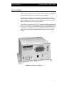
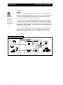
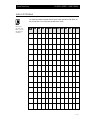
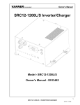
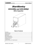
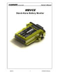
OWNER'S MANUAL
Model 20-1000TUL—AC Power Inverter System
OM/A96751 REV. A
20-1000TUL INVERTER—OWNER'S MANUAL
Vanner Power Group
Table of Contents
Section 1— Introduction .................................................................................... 1
Section 2— Installing the 20-1000TUL ............................................................. 4
Section 3— Installing the IFM1 Interface Module ............................................. 6
Section 4— Installing the Inverter Remote Status Display Panel ........................ 7
Section 5— Inverter Status Panel Operation ....................................................... 8
Section 6— Operating the 20-1000TUL Inverter .............................................. 9
Section 7— Troubleshooting ............................................................................. 10
Section 8 — GFCI Test Record ........................................................................ 11
Warranty ........................................................................................................... 12
List of Figures
Figure 1— System Diagram ................................................................................ 2
Figure 2— IFM1 Module Remote Wiring .......................................................... 7
Icon Legend
Note
Warning
VANNER POWER GROUP
4282 Reynolds Drive • Hilliard, Ohio 43026
Tel (614) 771-2718 • Fax (614) 771-4904
1-800-AC POWER
20-1000TUL—OWNERS MANUAL © Copyright 1996, Vanner Weldon, Inc.
OM/A96751 REV. A
20-1000TUL INVERTER—OWNER'S MANUAL
Vanner Power Group
Section 1: Introduction
Thank you for purchasing a Vanner 20-1000TUL Power Inverter for your emergency
vehicle. We are confident you will be satisfied with its performance.
Vanner products are designed and manufactured by skilled professionals using the
highest standards in workmanship, guaranteeing excellent performance and reliability
for your emergency vehicle. With minimum maintenance and care, you can expect
years of trouble-free service from your Vanner product.
The 20-1000TUL is a 12 VDC to 120 VAC inverter with a transfer relay and Ground
Fault Circuit Interrupter (GFCI) protected AC output. This unit is equipped with an
AC line cord for AC input power (shore/utility power) and a receptacle with a GFCI
for AC output. This enables you to plug AC loads directly into the inverter. The DC
cables have quick connectors to facilitate installation and pre-wiring of emergency
vehicles.
Vanner 20-1000TUL Inverter
—1—
20-1000TUL INVERTER—OWNER'S MANUAL
Vanner Power Group
Functionality
Inverter
WARNING
Battery input
cables must be
connected to
the battery
with proper
polarity to avoid
damaging the
inverter.
The 20-1000TUL converts battery power to 1050 Watts of 120 VAC modified sine
wave power to operate vital emergency vehicle equipment. The unit is easily connected
to the positive and negative posts of a battery system with appropriate fusing, and
when turned ON, produces 120 VAC True RMS power.
The inverter also has an energy-saving feature called Load Demand. With this feature,
the inverter output is pulsed, significantly reducing the current draw from the battery
until a demand is made on its output. Continuous output of 120 VAC resumes when a
load greater than 5 Watts is applied. The load demand feature can be disabled with the
Setup Switch on the front panel.
A built-in transfer relay senses AC input to the emergency vehicle (shore/utility power)
and connects the AC input directly to the GFCI receptacle. At that time, all equipment which was operating on the inverter is now powered by the AC shore line.
FIGURE 1—SYSTEM DIAGRAM
—2—
Vanner Power Group
20-1000TUL INVERTER—OWNER'S MANUAL
Specifications
Inverter
20-1000TUL
Output at 120 VAC RMS (Continuous Power Rating)
1050 Watts
Surge Capacity at 120 VAC (3 sec)
2100 Watts
Input Voltage, VDC
(Deep Cycle Battery Recommended)
Output Voltage
12 VDC, Nominal
10.5 VDC min., 16.0 VDC max.
120 VAC ± 5%
DC Current Draw (Batter
y)
(Battery)
OFF
0.017 Amps Typical
Load Demand (waiting)*
0.09 Amps Typical
Full ON at No Load
0.7 Amps Typical
Full ON with Load
Approx. AC Load Watts ÷ 10 or
AC Load Amps x 12
Frequency
Output Wave Form
60 Hz ± 0.1%
Modified Sine Wave
Bypass TTransfer
ransfer
Output Current, GFCI Outlet
12 Amps
Other Specifications
Ambient Temperature
Cooling Air
Chassis
Dimensions
Weight
-20o to +110oF, -29o to +43.4oC
Fan Cooled, 30 cfm
Aluminum
11.57”W x 5.94”H x 11.04”D
22 lbs
* Determined by Setup Switch on front panel
Remote Panel—D06638 & D06639
Remote Panel—D06638 & D06639
—3—
20-1000TUL INVERTER—OWNER'S MANUAL
Vanner Power Group
Section 2: Installing the 20-1000TUL
Unpacking the Inverter
`
NOTE
Air enters by the
fan at the rear of
the unit, and exits
through the sides
of the unit. For
maximum unit
performance, avoid
recirculating the
same hot air
through the unit.
Inspect the shipping container and equipment for loose or damaged parts.
If any damage is found, immediately notify the freight carrier.
Installing the Inverter
Step 1: Turn the inverter OFF/disconnect power to the wiring harness.
Make sure power to the vehicle wiring harness is disconnected. Verify
that the inverter is turned OFF by checking that the ON-OFF/RESET
Inverter Switch is in the OFF-RESET position.
(The button should NOT be pushed in.)
Step 2: Select a location for the unit.
An ideal installation location has the following characteristics:
• Close to the battery (within six feet using #2 AWG wire)
• Protected from the weather
• Well ventilated
DC Cable Length
Size
Maximum
2AWG
12ft.
1/O AWG
20 ft.
Step 3: Route DC input cables.
Route the negative and positive DC input cables from the inverter (through
the quick connector) to the battery. If required, protect cables where they
contact hard, sharp edges.
Step 4: Install in-line fuse.
Install an in-line Bussman ANN 125 or equivalent fuse (Vanner p/n 03640fuse and 03637-fuse holder) in the red, positive DC input cable between the
battery and inverter, within 18 in. of the battery or DC wiring bus system.
WARNING
Battery input
cables must be
connected to the
battery with
proper polarity
to avoid
damaging the
inverter.
—4—
Step 5: Connect Bonding Lug.
Use a AWG #8 or larger copper conductor to connect the chassis bonding lug
to the vehicle chassis and/or earth ground.
Step 6: Connect the inverter to the battery.
Connect the black, negative DC input cable from the quick connector to the
battery negative (-) terminal. This battery negative terminal is usually where
the battery negative connects to the engine block or frame.
Connect the red, positive DC input cable from the quick connector to the
fuse of the battery positive (+) terminal. This battery terminal is usually
connected to the DC electrical system at the load side of the Battery
Disconnect Switch.
20-1000TUL INVERTER—OWNER'S MANUAL
Vanner Power Group
Step 7: Select Load Demand option.
Select Load Demand option, if desired, using the proper switch position on
the front panel Setup Switch. With Load demand ON, the inverter conserves
battery energy and operates only when a load greater than 5 Watts is applied.
Step 8: Connect the AC loads.
Connect the AC loads to the inverter GFCI receptacle. Any time AC power is
applied to the AC input (shore/utility power), it will pass through this GFCI
receptacle.
Step 9: Verify installation.
Verify all connections are tight and secure for maximum performance.
Inverter LED Displays
Inverter
Battery Low
Overtemp
Overload
Light
Action
Description
Steady Green Light
Inverter is On and operating.
Single Blink Green Light
Inverter circuit is Off. Shore power is On and supplying
AC power to the AC loads. The inverter will turn On and
supply the load if shore power is lost.
Double Blink Green Light
Inverter circuit is Off. Shore power is Off. The inverter is
waiting for a load greater than 5 watts to be turned on.
Light
Description
Action
Solid Red
Inverter is On and the battery is almost too low to
operate the inverter.
Blinking Red
The inverter is Off. The battery voltage dropped below
10.5 volts DC and the inverter shut itself Off. Once shut
off, the batteries must be recharged. Then, the inverter
On/Off switch must be cycled to reset the unit.
Light
Description
Action
Solid Red
The unit is Off. The unit has turned itself Off because the
power MOSFET's are operating too hot. This can be
caused by operating an AC load which is too large for
the inverter, or lack of ventilation. When the unit cools
the inverter will start operating again.
Light
Description
Action
Blinking Red
The inverter is On but it is overloaded. Reduce the AC
load quickly or the inverter will shut off due to the
overload condition.
Solid Red
The inverter is Off. An overload has occurred and the
inverter has shut off to protect itself. Once shut off, the
inverter On/Off switch must be cycled to reset the unit.
—5—
20-1000TUL INVERTER—OWNER'S MANUAL
Vanner Power Group
Section 3:
Installing the IFM1 Interface Module
This section describes the installation of the optional Vanner Model IFM1 Interface
Module. Refer to the information provided in the IFM1 Interface Module Owner’s
Manual for more information on installing the inverter and interface module in a
vehicle rewired or retrofitted for the 20-1000TUL.
If you are installing a new 20-1000TUL unit, you will need the interface module only
if you are using the inverter status panel (p/n D06638), Remote Switch (p/n D06781),
or if you require the inverter lockout feature.
Installing the IFM1 Interface Module
Step 1: Mount the Interface Module.
Mount the interface module in the vehicle’s existing 12 V electrical system
wiring harness with #8 screws. Select a physical orientation best suited for
your application environment; however, it must be within the 2ft Interface
Cable length to the inverter. Additionally, the unit should not be installed
with pin connections facing upward.
Step 2: Connect the Inverter to the Interface Module.
Install the 2 ft. interface cable by plugging it into the remote RJ-11 connector
on the 20-1000TUL and the J1 connector on the IFM1 Interface Module.
Step 3: Connect the Battery Disconnect Switch.
Connect the +12 V lead from the Module Disconnect Switch circuit to the
inverter lockout Pin 1 (ignition switch or battery disconnect switch). The
+12 V lead from the Battery Disconnect Switch must be fused with an in-line
fuse or circuit breaker of 2 Amps or less. See Figure 2.
Step 4: Wire the Remote Switch (p/n D06781) to Pins 2 through 5.
Red to Pin 2, Black to Pin 3, Green to Pins 4 and 5. If no remote switch is
used, two jumpers must be installed. The first jumper connects Pin 2 to Pin
3, the second jumper connects Pin 4 to Pin 5. See Figure 2.
Step 5: Connect the Inverter Remote Status Display Panel (Optional).
Connect the gray, green, and red wires from the inverter panel, through the
OEM harness, to the IFM1 Module, Pins 6 (grey), 7 (green), and 8 (red).
—6—
20-1000TUL INVERTER—OWNER'S MANUAL
Vanner Power Group
Section 4:
Installing the Inverter Remote Status Display Panel
The Inverter Remote Status Display Panel (p/n D06638) contains separate, red and
green LED indicators. The green indicator light signifies the inverter is On or in
Standby mode. The red, Fault LED indicator shows problems such as over temperature, output overload, or low battery. The panel has a sealed overlay which mounts
easily on a flat surface. A 12-in. pigtail harness is included for easy installation. Use the
following procedure to install the Inverter Remote Status Display Panel.
Step 1: Select a location for the panel.
Identify the desired location for the inverter panel.
Step 2: Identify wires for installation.
Identify the gray, green, and red wires on the inverter panel and vehicle's
electrical system wires that will connect to the IFM1 Interface Module.
Step 3: Splice and arrange wires.
Splice together like-colored wires from the vehicle's electrical system to the
status panel using an insulated butt splice or equivalent. Carefully arrange the
wires such that the panel mounts flush against the surface to which it is
mounted.
Step 4: Secure panels to surface.
Mount the panels using #8 screws through the four holes in the panel.
FIGURE 2—
IFM1 MODULE
REMOTE WIRING
—7—
20-1000TUL INVERTER—OWNER'S MANUAL
Vanner Power Group
Section 5: Inverter Status Panel Operation
Two LEDs on the front of the Remote Status Display Panel indicate the status of the
inverter. The status indicated by the LED displays is directly related to the status
indicated by the LEDs on the front of the inverter.
Inverter LED
Inverter FFault
ault LED
Light Action
Description
Steady Green Light
Inverter is operational.
Single Blink-Green Light
Inverter is not being used. Shore power is applied to load. Inverter will
activate when shore power is
unavailable.
Double Blink-Green Light
Inverter is on in the Load Demand mode and is waiting for AC load to be
turned ON.
Light Action
Description
Red Light
Unit shutdown* — Check the inverter's front panel LEDs for reason of
shutdown: Low Battery, Overload, or Overtemp.
*Refer to the Troubleshooting section of this manual for fault diagnostic information.
Section 6: Operating the 20-1000TUL Inverter
—8—
Vanner Power Group
20-1000TUL INVERTER—OWNER'S MANUAL
Use the following instructions to operate the 20-1000TUL Inverter.
Step 1: Install the 20-1000TUL unit.
Completely install the inverter and charger using the instructions provided in
Section 2 of this manual.
NOTE
Throughout this
manual, shore/
utility power is
referred to as AC
input power.
Step 2: Apply an AC load.
Apply an AC load with AC input power present. The AC load is run directly
from AC input power. The ON-OFF/RESET Inverter Switch does not affect
the inverter's AC output when shore power is present.
Step 3: Turn on the inverter Remote Switch.
Step 4: Apply shore power to the 20-1000TUL/Ambulance shore line connection.
Push the ON-OFF/RESET Inverter Switch to the ON position. When
powered by the AC power, the ON lamp flashes, indicating that the inverter
is standing by.
Step 5: Verify Power.
Apply an AC load, such as a shop light or drill. The AC load is run directly
from AC input power.
Step 6: Observe the inverter operation.
Remove the shore line connection from the emergency vehicle. The unit will
automatically switch to Inverter mode and operate the AC load using battery
power. When shore power is restored, the unit examines the AC input for five
seconds and then switches the loads back to run directly from AC input
power.
With the ON-OFF/RESET Switch in the ON position, a double flash of the
ON light indicates the load demand is turned ON and the load is less than
5 Watts.
—9—
20-1000TUL INVERTER—OWNER'S MANUAL
Vanner Power Group
Section 7: Troubleshooting the 20-1000TUL
The following are the most common questions heard by Vanner service professionals.
If your situation does not apply to the following categories, please contact your local
Vanner Power Group Service Center.
Vanner Power Group Customer Service:
1-800-AC-POWER
SYMPT
OM
SYMPTOM
The LEDs on the front panel blink in sequence.
SOL
UTION
SOLUTION
It is normal for this to occur if the inverter switch is On when the DC input is connected to the unit.
If the DC is already connected and the LEDs blink in sequence then the DC input voltage is dropping.
Check for poor connections in the DC wiring, bad battery or a heavy DC load.
SYMPT
OM
SYMPTOM
ON lamp does not light steadily after pushing in the ON-OFF/RESET
Switch.
SOL
UTION
SOLUTION
Lamp flashes when utility power is present.
Inverter
Lamp flashes in Load Demand Waiting mode.
Check/Reset GFCI on the receptacle.
Check battery connections if utility power is OFF.
Check DC fuses if utility power is OFF.
SYMPT
OM
SYMPTOM
ON lamp fully illuminates. AC load does not run.
SOL
UTION
SOLUTION
Check and reset circuit breaker.
Verify AC load and cord are in proper condition.
SYMPT
OM
SYMPTOM
BATTERY LOW lamp illuminates when AC load is applied.
SOL
UTION
SOLUTION
Check battery connections.
Check battery condition.
Recharge battery if voltage is less than 10.5 VDC.
Check AC loads for shorted circuit.
Check the vehicle's alternator charging system for proper operation.
— 10 —
SYMPT
OM
SYMPTOM
OVERTEMP lamp illuminates.
SOL
UTION
SOLUTION
Something has caused the unit to overheat. Check for obstruction of air flow to the cooling fan or from
ventilation holes.
Verify AC load is within unit’s rated
capacity.
SYMPT
OM
SYMPTOM
OVERLOAD lamp illuminates with AC load applied.
SOL
UTION
SOLUTION
Verify AC load is within unit’s rated capacity.
SYMPT
OM
SYMPTOM
DC fuse blows when connecting DC input cables.
SOL
UTION
SOLUTION
Check for reverse polarity: red cable to battery positive (+), black cable to battery negative (-). The
unit may be damaged and require repair service.
20-1000TUL INVERTER—OWNER'S MANUAL
Vanner Power Group
Section 8: GFCI Test Record
For maximum protection against electrical shock hazard, operate the Test Switch on
the Ground Fault Circuit Interrupter at least once a month.
NOTE
Photocopy
this page and
place it in your
maintenance
notebook.
ENTER
YEAR
JAN
FEB M A R
APR
M A Y J U N E J U LY
AUG SEPT
OCT NOV
DEC
19____
— 11 —
Limited Warranty
1. Vanner Weldon, Inc., referred to herein as Vanner, warrants that this
product is free from defects in materials and workmanship for a period of
one (1) year from its date of shipment from Vanner's factory.
2. This warranty does not cover defects caused by misuse, neglect, accident,
reversed polarity, unauthorized repairs, and/or replacements.
3. All warranties of merchantability and fitness for a particular purpose;
written or oral, express or implied, shall extend only for a period of one
(1) year. There are no other warranties which extend beyond those
described on the face of this warranty.
4. Vanner does not undertake responsibility to any purchaser of its product
for any undertaking, representation, or warranty made by any dealers or
distributors selling its products beyond herein expressed.
5. Vanner does not assume responsibility for incidental or consequential
damages, including, but not limited to responsibility for loss of use of this
product, loss of time, inconvenience, expense for telephone calls, shipping
expense, loss or damage to property, or loss of revenue.
6. Vanner reserves the right to repair, replace, or allow credit for any
material returned under this warranty. Any damage caused by the
customer will be charged or deducted from the allowance.
7. All warranty work will be performed at Vanner's factory, or authorized
repair facility. Products shall be delivered to Vanner's facility, freight
prepaid. Products repaired under warranty, or replacement parts or
products will be returned, F.O.B. Vanner factory.
— 12 —
Vanner PPower
ower Group
4282 Reynolds Drive
Hilliard, Ohio 43026
Tel (614) 771-2718
Fax (614) 771-4904
Specifications Subject to Change
© Copyright 1996, Vanner Weldon Inc.
Printed in the U.S.A.
OM/A96751 REV. A 5/96