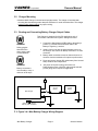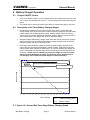
1
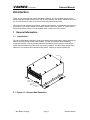
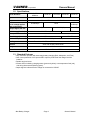
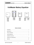
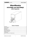
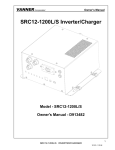
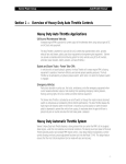
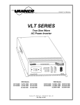
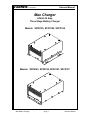
VANNER Incorporated
Owners Manual
Max Charger
24Volt 42 Amp
Three Stage Battery Charger
Models: SP00155, SPC0182, SPC0184
Models: SP00143, SP00180, SP00181, SPC0187
Max Battery Charger
Page 1
Owner’s Manual
VANNER Incorporated
Owners Manual
Table of Contents
1 Introduction.................................................................................................... 3
2 General Information ...................................................................................... 3
2.1
Introduction and Checkout ................................................................. 3
2.2
Specifications ..................................................................................... 4
2.3
Standard Features ............................................................................. 4
3 Installation and Checkout ............................................................................. 5
3.1
Selection of Battery Charger Location................................................ 7
3.2
Charger Mounting .............................................................................. 8
3.3
Routing and Connecting Battery Charger DC Output Cables............. 8
4 Battery Charger Operating Procedure ......................................................... 9
4.1
Charger Setup .................................................................................... 9
4.2
Charging Stages ................................................................................ 9
5 Operation LED ............................................................................................. 10
5.1
LED Status ....................................................................................... 10
Figures
F 1 Figure 2.1-1 Vanner Max Illustration ......................................................................................... 3
F 2 Figure 3.4-1 Max Battery Charger Wiring Diagram ................................................................... 8
F 3 Figure 4.2-1 Max Three-Stage Battery Charging Graph ........................................................... 9
Max Battery Charger
Page 2
Owner’s Manual
VANNER Incorporated
Owners Manual
Introduction
Thank you for purchasing the Vanner Max Battery Charger. We are confident that you will be
satisfied with this charger's performance and its many features. With proper installation and care,
you can look forward to years of service from this high performance product.
This document will describe the operation, technical specifications, and installation procedures of
this product. If you require additional information please contact your dealer, or contact Vanner
directly at the phone number or email address shown on the back of this manual.
1 General Information
1.1
Introduction
The Vanner Max Battery Charger is a high performance three-stage battery charger that has the
ability to precisely charge 24VDC battery banks. The Max incorporates advanced battery
charging technology, correctly charging batteries automatically at the charger’s rated ampere
output rather than tapering off like some other battery chargers. This three-stage design keeps
batteries in top condition and minimizes battery failure, resulting in maximum battery life.
FAN
FLOAT
GREEN
BULK
AMBER
OVERTEMP
RED
F 1 Figure 2.1-1 Vanner Max Illustration
Max Battery Charger
Page 3
Owner’s Manual
VANNER Incorporated
1.2
Owners Manual
Specifications
Model Numbers
SP00143, SP00180,
SP00181
Input
SP00155
SPC0184
SPC0182
SPC0187
15A at 120VAC ±10%, 60Hz ±10%
Output
42A at 24VDC Nominal, 4AWG cables
DC Current Draw with
no AC voltage applied
30 milliamps
“AC is connected”
Output Signal, 4A max
Bulk Voltage (Nominal)
Ground (B-)
+24VDC (B+)
28.6VDC
Absorption Time
Float Voltage (Nominal)
Ambient Temperature
30
milliamps
None
Ground (B-)
29.8VDC
20 Minutes
26.6VDC
27.4VDC
-40 to +105°F (-40 to +40°C)
Cooling
Forced Air, 100 CFM, 24VDC Fan with front to rear air flow
Chassis
Steel with durable painted finish
Weight
35 lbs
Dimensions
1.3
9.85" W x 6.70" H x 15.75" D
Standard Features
• Fully automatic operation with three-stage battery charging (Bulk, Absorption, and Float)
• Over current protection of AC input and DC output to protect both the charger and the
batteries
• Durable steel enclosure
• 3 Status LED’s indicating: charging status (green and yellow), over temperature fault (red),
and wiring disconnected (blinking green).
• Output signal to indicate that the charger is connected to 120VAC.
Max Battery Charger
Page 4
Owner’s Manual
VANNER Incorporated
Owners Manual
2 Installation Instructions
These symbols are used to note procedures that if not closely followed could lead to loss of life or
damage to equipment or property due to electrocution.
Electrocution hazard exists
Fire hazard exists
A potentially dangerous condition
Explosive hazard exists
Corrosive hazard exists
Fault protection devices must be installed between the charger and
the battery. A fault protection device would be any fuse or circuit breaker properly rated for the
maximum DC current obtainable. This advisory is in accordance with SAE, NEC and UL, for
mobile power applications. Install per applicable codes or within 18” of the battery. Contact
Vanner at 1-800-227-6937 or [email protected] if assistance is needed in sizing fault
protection devices.
Caution: This equipment tends to produce arcs and sparks during
installation. To prevent fire or explosion, compartments containing batteries or flammable
materials must be properly ventilated. Safety goggles should always be worn when working near
batteries
WARNING: Before installing and using the MAX Charger, be sure to read
and save these safety instructions.
This manual contains important safety and operating instructions for the Vanner MAX Battery
Charger
CAUTION:
Read owners manual BEFORE wiring or powering up.
CAUTION:
DO NOT cover or obstruct ventilation openings. DO NOT mount in a zeroclearance compartment. Overheating may result.
WARNING:
Under high ambient temperature / high-power-output conditions some parts of
the charger may become hot enough to cause burns. The unit should be installed
so that it is not to be contacted by personnel.
WARNING:
Improper use of this product may result in risk of electrical shock. Both AC and
DC voltage sources are terminated inside this equipment.
Warning:
Battery connections are for disconnect only, NOT for current interruption.
Max Battery Charger
Page 5
Owner’s Manual
VANNER Incorporated
Owners Manual
2.1 General Precautions
Do not expose the charger to direct water spray or snow.
To reduce the risk of a fire hazard, do not cover or obstruct the ventilation openings.
Do not install the charger in a zero clearance compartment. This may result in
overheating or diminished performance.
To avoid the risk of fire, electrical shock, or injury to persons, do not use
attachments not recommended or sold by the Vanner Inc.
Vanner recommends that all AC and DC electrical wiring be performed by a licensed
electrician or a qualified technician to ensure compliance with all applicable national and local
wiring regulations.
To avoid a risk of fire and/or electrical shock, always verify wiring
connections are in good electrical condition. All external conductors must use proper wire
size to avoid dangerous overheating or diminished performance.
If the charger has been dropped or damaged in any way, do not operate the charger
until it has been verified to be safe by a qualified technician.
To reduce the risk of electrical shock, always disconnect the AC and DC connections
to the charger before attempting any maintenance. Simply turning the charger off does not
prevent electrical shock.
The charger must be properly grounded in accordance with local and national codes
and ordinances before operation. For most installations, the negative (ground) conductor
should be bonded to the grounding system at one and only one point in the system.
For optimum charger performance, battery temperature should be above 32 degrees
Fahrenheit.
Do not disassemble the charger. See the service section of this manual for
instructions on obtaining service. Attempting to service the inverter yourself may result in a
risk of electrical shock, fire and/or loss of warranty.
Max Battery Charger
Page 6
Owner’s Manual
VANNER Incorporated
Owners Manual
To reduce the risk of battery explosion, follow these instructions, the battery
manufacturer instructions, and the instructions of the manufacturer of the equipment in which
the battery is installed. Working near a lead-acid battery is dangerous. Batteries generate
explosive gases during normal battery operation.
2.2 Battery Precautions
1. Always have someone within range of your voice to come to your aid when you work near a
lead-acid battery.
2. Have close access to plenty of fresh water and soap in case battery acid contacts skin,
clothing, or eyes.
3. Always wear complete eye protection and clothing protection. Avoid touching eyes while
working near batteries.
4. If battery acid contacts skin or clothing, wash immediately with soap and water. If acid enters
eye, immediately flood eye with running cold water for at least 20 minutes. Get medical
attention immediately.
5. NEVER smoke or allow a spark or flame near a battery. Gases produced by batteries are
explosive.
6. Be careful when working with metal tools around batteries. Potentials exist for sparks or
short-circuit of the battery or other electrical part which could cause an explosion.
3 Installation and Checkout
3.1 Selection of Battery Charger Location
NOTE
Charger should not
be installed in same
compartment as batteries
where corrosive or explosive
gases are present.
Max Battery Charger
• Charger should be located close to battery. Locate within 3’ for
optimum performance, but not in the same compartment.
• Charger should be protected from weather. Install in a location
that provides protection from direct water spray and dirt.
• Mounting compartment should be well-ventilated and allow
adequate air circulation for charger cooling. Allow 2" clearance
around entire charger.
• Do not store flammable items near charger. Do not expose
charger to corrosive or explosive vapors.
Page 7
Owner’s Manual
VANNER Incorporated
3.2
Owners Manual
Charger Mounting
• Install the MAX Charger in the horizontal upright position. The charger is furnished with
mounting brackets which provide adequate clearance for under chassis airflow. The charger
requires under chassis airflow for proper cooling.
3.3
Routing and Connecting Battery Charger Output Cables
This Charger is designed for 24 VDC applications only. If
connected to other than 24V system, damage will result.
WARNING
Safety goggles
should be worn
when working with
or near batteries
1. Connect the Max Charger's RED cable to the battery's
positive (+) terminal and the BLACK cable to the
Battery's negative (-) terminal.
2. Install a fuse in line with the positive battery source to
the charger. Size fuse at an 80Amp minimum to a 150A
maximum.
3. Battery cable connections must be clean and secure to
minimize electrical resistance for optimum performance.
4. Route and secure charger DC cables away from Hot and
Sharp surfaces and components.
WARNING
Battery connections
must be able to carry a
minimum of 50 amps.
5. “AC power is Present” mating connection is a
Delphi Weather-Pack 12015791 with terminal selected
per the gauge wire required for application.
+
12 Volt
Battery
-
+
12 Volt
Battery
-
MAX Charger
Output Signal notifying
that AC power is Present
F 2 Figure 3.4-1 Max Battery Charger Wiring Diagram
Max Battery Charger
Page 8
Owner’s Manual
VANNER Incorporated
Owners Manual
4 Battery Charger Operation
4.1
Charger ON/OFF Control
1. There is no ON/OFF switch. Turn the charger ON by connecting the AC input line cord
to a 15 Amp 120 Volt 60Hz power source. Turn the charger OFF by disconnecting AC
power.
2. The charger will not accept AC power above 65Hz or voltage below approx 100 VAC.
4.2
Description of the Three Battery Charging Stages
1. Charging begins when the unit receives 120VAC shore power. In Bulk Stage the
charger output amps will be at full rated output and battery voltage will rise until battery
voltage reaches the models specified voltage. Battery voltage is held by reducing
output current as needed. Bulk Stage ends when charger output current is reduced to
75% of rated output. The charger then shifts to Absorption Stage.
2. Absorption Stage holds battery voltage at the stated bulk rate for 20 minutes. Charger
output current will vary as needed to hold battery voltage constant. After 20 minutes
Absorption Stage ends and Float Stage begins.
3. Float Stage holds the battery voltage at models specified voltage. Charger output
current will vary as needed to hold battery voltage constant. Float Stage ends when
charger output amps reaches full rated output. (In a normal situation the charger will
cycle to Float Stage one time and then remain in Float Stage until disconnected from
AC power. Please note: DC LOADS may cause the charger to reach full output
which will cause Bulk Stage to restart. The batteries may be damaged due to
overcharging if DC LOADS cause Bulk Stage to restart repeatedly.)
30
100
Bulk Mode
90
Absorption M ode for 20 minutes
25
Float Mode
80
75% Rated Current
Battery Voltage
70
20
60
15
50
40
10
30
20
5
10
0
0
0
2.5
5
7.5
10
12.5
15
17.5
20
22.5
Time in Minutes
25
27.5
30
32.5
35
37.5
40
---
% Rated Charging Amps
──
Battery Voltage
F 3 Figure 4.2-1 Vanner Max Three-Stage Battery Charging Graph
Max Battery Charger
Page 9
Owner’s Manual
VANNER Incorporated
Owners Manual
5 Operation
LED Status Indicators for Models SP00143, SP00180, SP00181 and SPC0187
LED
Charger Status
Yellow solid
The charger is ON and is in Bulk Stage or Absorption Stage.
Green solid
The charger is ON and is in Float Stage.
Red solid
The charger is OFF because internal temperature is too high. Shutdown may
have been caused by high ambient temperature or by restricted cooling air flow.
The charger will automatically restart when internal temperature is acceptable.
Green
BLINKING
The charger is OFF. Either 120VAC is disconnected or battery is disconnected.
No LED’s
The charger is OFF and is disconnected from both 120VAC and battery.
LED Status Indicators for Models SP00155, SPC0182 and SPC0184
LED
Charger Status
Yellow solid
The charger is ON and is in Bulk Stage or Absorption Stage.
Green solid
The charger is ON and is in Float Stage.
Red solid
The charger is OFF because internal temperature is too high. Shutdown may
have been caused by high ambient temperature or by restricted cooling air flow.
The charger will automatically restart when internal temperature is acceptable.
Green
Blinking
The charger is OFF. The charger is connected to 120VAC but is disconnected
from battery.
No LED’s
The charger is OFF because 120VAC is disconnected. (Battery connection
status is not defined.)
Max Battery Charger
Page 10
Owner’s Manual
VANNER Incorporated
Owners Manual
Notes:
Max Battery Charger
Page 11
Owner’s Manual
VANNER Incorporated
Owners Manual
Vanner Incorporated
4282 Reynolds Drive
Hilliard, Ohio 43026
1-800-AC POWER
(1-800-227-6937)
Tel: 614-771-2718
Fax: 614-771-4904
www.vanner.com
e-mail: [email protected]
Manual Number D97598-F
January 28, 2013
Max Battery Charger
Page 12
Owner’s Manual