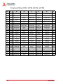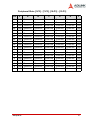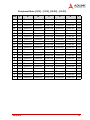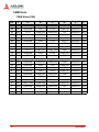
1
cPCIS-3320 Series
9U Dual-System
CompactPCI Platform
User’s Manual
Manual Rev.
2.00
Revision Date:
April 20, 2005
Part No:
50-15037-100
Advance Technologies; Automate the World.
Copyright 2005 ADLINK TECHNOLOGY INC.
All Rights Reserved.
The information in this document is subject to change without prior
notice in order to improve reliability, design, and function and does
not represent a commitment on the part of the manufacturer.
In no event will the manufacturer be liable for direct, indirect, special, incidental, or consequential damages arising out of the use or
inability to use the product or documentation, even if advised of
the possibility of such damages.
This document contains proprietary information protected by copyright. All rights are reserved. No part of this manual may be reproduced by any mechanical, electronic, or other means in any form
without prior written permission of the manufacturer.
Trademarks
Product names mentioned herein are used for identification purposes only and may be trademarks and/or registered trademarks
of their respective companies.
Getting Service from ADLINK
Customer Satisfaction is top priority for ADLINK Technology Inc.
Please contact us should you require any service or assistance.
ADLINK TECHNOLOGY INC.
Web Site:
http://www.adlinktech.com
Sales & Service:
[email protected]
TEL:
+886-2-82265877
FAX:
+886-2-82265717
Address:
9F, No. 166, Jian Yi Road, Chungho City,
Taipei, 235 Taiwan
Please email or FAX this completed service form for prompt and
satisfactory service.
Company Information
Company/Organization
Contact Person
E-mail Address
Address
Country
TEL
FAX:
Web Site
Product Information
Product Model
Environment
OS:
M/B:
Chipset:
CPU:
BIOS:
Please give a detailed description of the problem(s):
Table of Contents
List of Figures ........................................................................ iii
1 Introduction ........................................................................ 1
1.1
1.2
1.3
1.4
1.5
1.6
Features............................................................................... 1
Specifications....................................................................... 2
Mechanical Layout............................................................... 3
cPCIS-3320 Series Mechanical Layout .......................... 3
cPCIS-3320 Series External Dimensions (mm) .............. 4
cPCIS-3320 Configurations ................................................. 5
System Architecture............................................................. 5
cPCIS-3320/AC: Standard Alarm Board ......................... 6
cPCIS-3320/M/AC: Optional CMM ................................. 7
Power Distribution................................................................ 8
2 Getting Started ................................................................... 9
2.1
2.2
2.3
2.4
2.5
2.6
Shipping Contents ............................................................... 9
CompactPCI Computing Blade & PSU Installation.............. 9
CompactPCI Card Installation/Removal Procedure ...... 10
CompactPCI PSU Installation/Removal Procedure ...... 12
Rear Transition Module Installation/Removal .................... 13
Drive Bay Access............................................................... 14
Powering Up the System ................................................... 15
System Alarm Board.......................................................... 16
3 Backplane ......................................................................... 17
3.1
3.2
3.3
3.4
Specifications..................................................................... 17
Mechanical Drawing .......................................................... 18
Connector Pin Assignments .............................................. 20
System Slots ................................................................. 20
Peripheral Slots ............................................................ 25
CMM Slots .................................................................... 30
Other Connectors ......................................................... 32
Jumper Settings................................................................. 36
Table of Contents
i
4 Cooling System................................................................. 39
4.1
4.2
4.3
Fan Alarm .......................................................................... 39
Fan Removal and Replacement ........................................ 39
Intake Fans ................................................................... 40
Exhaust Fan .................................................................. 41
Fan Tray Filter Replacement ............................................. 43
5 Power Supply Unit ............................................................ 45
5.1
5.2
5.3
5.4
5.5
Features.............................................................................
Specifications.....................................................................
Input Characteristics ..........................................................
Output Characteristics .......................................................
Pin Assignments ................................................................
45
45
46
47
48
6 Chassis Management Module.......................................... 49
6.1
6.2
6.3
CMM Overview .................................................................. 49
CMM Mechanical Diagrams .......................................... 50
CMM System Management Architecture ...................... 52
Features ........................................................................ 52
Specifications ................................................................ 53
CMM Setup ....................................................................... 54
CMM Firmware Update...................................................... 60
Important Safety Instructions............................................... 65
Warranty Policy ..................................................................... 67
ii
Table of Contents
List of Figures
Figure 1-1:
Figure 1-2:
Figure 1-3:
Figure 1-4:
Figure 1-5:
Figure 1-6:
Figure 1-7:
Figure 1-8:
Figure 2-1:
Figure 2-2:
Figure 2-3:
Figure 2-4:
Figure 2-5:
Figure 2-6:
Figure 3-1:
Figure 3-2:
Figure 4-1:
Figure 4-2:
Figure 4-3:
Figure 4-4:
Figure 4-5:
Figure 4-6:
Figure 6-1:
Figure 6-2:
Figure 6-3:
List of Figures
Mechanical Layout of the cPCIS-3320 ...................... 3
cPCIS-3320 Series Front View.................................. 4
cPCIS-3320 Series Side View ................................... 4
cPCIS-3320/AC Architecture (Front View) ................ 6
cPCIS-3320/AC Architecture (Rear View) ................. 6
cPCIS-3320/M/AC Architecture (Front View) ............ 7
cPCIS-3320/M/AC Architecture (Rear View) ............. 7
cPCIS-3320 Series power distribution....................... 8
cPCIS-3320 Series slot layout................................. 10
Installing 6U modules. ............................................. 11
Latching the cPCI module handles securely. .......... 12
Unlatching and removing a cPCI PSU..................... 13
5.25” drive bay access............................................. 14
cPCIS-3320 switch and LED legend. ...................... 15
cBP-6413DR Backplane Front View........................ 18
cBP-6413DR Backplane Rear View ........................ 19
Remove the intake fan tray cover............................ 40
Remove the screws securing the fan module.......... 40
Remove the faulty intake fan module ...................... 41
Remove the exhaust fan tray cover......................... 41
Remove the screws securing the fan module.......... 42
Remove the faulty exhaust fan module ................... 42
cPCI-8603 Top, Front and Side View ...................... 50
cPCI-R8603 RTM Top and Front View.................... 50
N2525A CMM module Top and Isometric View....... 51
iii
iv
1
Introduction
The cPCIS-3320 Series 9U Dual-System Platform is ideal for
developing telecom applications focusing on media and signaling
gateways, as well as telecom value-added services like Location
Based Service (LBS), Ring Back Tone (RBT), and Multimedia
Message Systems (MMS).
This flexible and reliable development platform with optimized I/O
and storage provides the best solution for equipment manufacturers and system integrators and shortens time-to-market for fast
growing business revenues.
The cPCIS-3320 supports dual systems and two 5.25” drive bays.
System A (left side) supports 1+7 slots (1 host slot + 7 peripheral
slots), and System B (right side) supports 1+4 slots (1 host slot
and 4 peripheral slots). Both segments support 64-bit/66MHz PCI
and H.110 CT buses.
1.1 Features
X
Standard 6U CompactPCI
X
PICMG 2.9 compliant & H.110 CT Bus
X
Dual System support
X
System A: 1 + 7 (1 host slot + 7 peripheral slots)
X
System B: 1 + 4 (1 host slot + 4 peripheral slots)
X
N+1 (750W + 250W) hot swappable redundant cPCI power
X
Optional PICMG 2.9 Chassis Management Module (CMM)
with Intelligent Platform Management Interface (IPMI) for
remote monitoring and control of the system via Ethernet
X
64-bit/66MHz cPCI bus
X
6-fan (5 lower intake + 1 upper exhaust) hot swappable
redundant cooling architecture with removable air filter
X
2 conventional upper exhaust fans
X
Designed for NEBS Level 3 compliance
Introduction
1
1.2 Specifications
CompactPCI Standards
PICMG 2.0; 2.1; 2.5; 2.9; 2.11
Form Factor
6U cPCI with 80 mm depth rear I/O
Enclosure
EIA RS-310C 19" 9U high rack-mount enclosure
Coated metal plate outer covering
Guarded power switch and reset button
Basic Alarm Module
(model dependent)
Monitors inner chassis temperature & fan status (model
dependent)
Abnormal status will generate alarm and LED warning
Audible alarm reset
LED indicators display voltage status on 5V, 3.3V, 12V, -12V
Remote Chassis
Monitoring Module
(model dependent)
Basic Alarm functions plus: Monitors boards via the
Intelligent Platform Management Interface (IPMI)
Monitors backplane voltages and power supply status
Remote login and management via LAN or modem
Remote reset control for host boards
Web-based GUI for both remote and stand-alone
applications
Cooling System
Front access hot swappable fan trays for intake and
exhaust:
12V DC brushless, dual ball bearing
5 fans for intake and 1 fan for exhaust
Rated power for each fan: 2.64W
Air flow for intake: 241 CFM
Air flow for exhaust: 48.2 CFM
Two upper blower fans (22.4 CFM, 4.56W each)
Drive Bays
Two 5.25” drive bays
Power Supply
Supports up to 4 in-rack 3U cPCI 8HP power modules
Supports current sharing on 5V, 3.3V and 12V
PICMG 2.11 47-pin power interface
Available power module: cPS-H325/AC (250W N+1
redundant each)
Dimension
483.2 x 399 x 299.1 (mm, WxHxD, w/o handles)
Operating temperature
0 to 50°C
Storage temperature
-20 to 80°C
Humidity
5% to 95%, non-condensing
Safety, Certification, EBS CE, FCC class A, Designed for NEBS Level 3
Recommended System
Boards
2
cPCI-6810, cPCI-6820, cPCI-6830V, cPCI-6831,
cPCI-6840, cPCI-6841, cPCI-6842, cPCI-6860A
Introduction
1.3 Mechanical Layout
Refer to the figures below for the mechanical layout and external
dimensions of the cPCIS-3320.
cPCIS-3320 Series Mechanical Layout
Figure 1-1: Mechanical Layout of the cPCIS-3320
Introduction
3
cPCIS-3320 Series External Dimensions (mm)
Figure 1-2: cPCIS-3320 Series Front View
Figure 1-3: cPCIS-3320 Series Side View
4
Introduction
1.4 cPCIS-3320 Configurations
The cPCIS-3320 Base Model comes in the configurations shown
in the table below. The “M” designation indicates the optional
Chassis Management Module (CMM).
Model Number
Management System
cPCIS-3320/AC
Standard Alarm Board
cPCIS-3320/M/AC
CMM
1.5 System Architecture
The cPCIS-3320 Series uses the system architecture shown in
the figures below. System A supports 1+7 slots and System B supports 1+4 slots. All configurations come standard with four 250W
CompactPCI power supplies installed. The “M” designation model
comes with the CMM and its Rear Transition Module (RTM)
installed.
Introduction
5
cPCIS-3320/AC: Standard Alarm Board
Figure 1-4: cPCIS-3320/AC Architecture (Front View)
Figure 1-5: cPCIS-3320/AC Architecture (Rear View)
6
Introduction
cPCIS-3320/M/AC: Optional CMM
Figure 1-6: cPCIS-3320/M/AC Architecture (Front View)
Figure 1-7: cPCIS-3320/M/AC Architecture (Rear View)
Introduction
7
1.6 Power Distribution
The cPCIS-3320 Series a redundant power supply distribution as
shown in figure below. The CMM portion of the diagram applies to
the cPCIS-3320/M/AC model and indicates the fan status monitored by
the CMM.
Figure 1-8: cPCIS-3320 Series power distribution
8
2
Getting Started
This chapter describes the unpacking procedure of the sub-system and installation procedures for CompactPCI boards, power
supply units (PSUs) and drive bays.
2.1 Shipping Contents
Check the shipping carton for any damage. If the shipping carton
and contents are damaged, please notify the dealer for a replacement. Retain the shipping carton and packing material for inspection by the dealer. Obtain authorization before returning any
product to ADLINK.
Check that the following items are included in the package. If there
are any missing items, please contact your dealer:
X
One cPCIS-3320 Series platform
X
This User’s Manual
X
Accessory Kit (includes N. American or European power
cord, air filter and spare screws)
2.2 CompactPCI Computing Blade &
PSU Installation
The CompactPCI connectors are rigid and require careful handling
when inserted and removed. Improper handling of cards can easily damage the backplane.
The host board slot is red, peripheral slots are gray, and PSU slots
are green. The Chassis Management Module (CMM) slot is also
gray, but the pin connector of the CMM is different than that of the
peripheral board. Be certain to insert each module into the correct
type of slot. The slot left of the PSU slots shown in the figure below
is for CMM use only.
Host board slots have obvious indicators (e.g. red card guide rail,
triangle mark enclosing the slot number on the backplane) A host
board can only be installed in a host board slot. Do not insert a
host board into any other slot, or insert any peripheral card into a
host board slot.
Getting Started
9
Figure 2-1: cPCIS-3320 Series slot layout.
The handles on CompactPCI cards and PSUs ensure simple and
safe installation and removal. Please follow the procedures below
to install a CompactPCI module into a chassis:
CompactPCI Card Installation/Removal Procedure
1. Place the sub-system on a level surface or rackmount it.
Remove the blanking plates where required by undoing
the retaining screws at each end. Retain the blanking
plates for possible future use. The system should not be
put into use without blanking plates for all empty slots,
otherwise the EMC and cooling performance will be
compromised
2. Hold the host board or peripheral card module vertically.
Make sure that the handles are unlatched (i.e. that they
10
Getting Started
are pulled outwards) by first pressing on the release buttons with your thumb.
3. Carefully insert the module into the desired slot by sliding the edges of the board into the appropriate card
guide rail. Take care to ensure correct alignment of the
card with the chassis during insertion to prevent damage
to the card and/or backplane.
Figure 2-2: Installing 6U modules.
4. Continue inserting the card until the handles engage with
the chassis.
Getting Started
11
Figure 2-3: Latching the cPCI module handles securely.
5. Push inwards on the handles for final insertion. Ensure
that the buttons on the handles fully latch into position as
unless this is done the card is not correctly inserted. Fasten the retaining screws at each end of the card (2 for
single slot cards, 4 for double slot cards).
6. To remove the module, undo the retaining screws, press
the release buttons (if necessary), and reverse steps 1
through 5 above.
CompactPCI PSU Installation/Removal Procedure
The cPCIS-3320 Series come with cPS-H325 PSUs pre-installed.
The removal and installation procedures for PSUs are the same
as for CompactPCI cards, except there is only one handle. To
replace a PSU module, refer to the figures and instructions below.
1. To remove the PSU module, undo the retaining screws
and unlatch the handle by pressing on the release button.
12
Getting Started
Figure 2-4: Unlatching and removing a cPCI PSU.
2. Pull outwards to remove the PSU.
3. Insert the new PSU module, push on the handle until it
latches into position, and replace the retaining screws.
2.3 Rear Transition Module Installation/Removal
The installation and removal procedures for a Rear Transition
Module (RTM) are the same as those for CompactPCI boards.
Because they are shorter than front boards, pay careful attention
when inserting or removing RTMs. Only models with an “R” at the
end of the model number support RTMs.
Note: We strongly recommended the use of RTMs with AB type
connectors to prevent the damage to the backplane during
RTM installation.
Getting Started
13
2.4 Drive Bay Access
To install the required hardware in the two 5.25” drive bays, follow
the procedure below:
1. Remove the 16 screws fastening the chassis lid and lift it
off of the cPCIS-3320.
2. Remove the three screws fastening the drive bay
bracket to the internal chassis structure as shown in the
figure below. Remove the bracket from the chassis, undo
the four screws attaching the blanking cover to the drive
bay bracket, and remove the blanking cover.
Figure 2-5: 5.25” drive bay access.
3. Install the necessary hardware into the drive bay
bracket, replace the bracket into the chassis, and fasten
the screws attaching it to the internal chassis structure.
4. Make the necessary cable connections and replace the
chassis lid.
14
Getting Started
2.5 Powering Up the System
Connect the supplied power cord to the socket on the back of the
chassis. All supplied PSUs are full range 90-240VAC and do not
require input voltage setting. Insert the desired boards into the
appropriate card slots as described in Section 2.2 and 2.3.
The cPCIS-3320 Series features a guarded power switch. Use a
suitably shaped object (such as a pen) to actuate the power
switch. After the system is powered up, all LEDs will light up to
indicate normal operating conditions.
Figure 2-6: cPCIS-3320 switch and LED legend.
Getting Started
15
2.6 System Alarm Board
The cPCIS-3320/AC features an embedded alarm board that
monitors temperature and fan status. Should a fan become disabled or the temperature exceed 50°C, the Alarm LED will light up
and an audible warning will be heard.
To disable the audible warning, press the Alarm RST button. The
Alarm LED will continue to flash until the fault is corrected.
The cPCIS-3320/M/AC features the optional Chassis Management Module (CMM) that provides a remote management interface for both chassis and board management. See Chapter 6 for
details.
16
Getting Started
3
Backplane
In this chapter, we will describe the backplane for the cPCIS-3320
Series, the cBP-6413DR, a dual-system 64-bit 6U CompactPCI
H.110 bus backplane.
3.1 Specifications
CompactPCI
Standards
PICMG 2.0 R3.0, 2.1 R2.0, 2.5 R1.0, 2.9 R1.0,
2.11 R1.0
Dimensions
415.56 x 262.05 (mm, W x H)
Segments
Two
CompactPCI Bus
Up to 64-bit/66MHz
System Slots
Two (R-hand side)
System Slot
Rear I/O
P3, P4, and P5 rear I/O with AB-type shroud
Peripheral Slots
System A: 7, System B: 4
Peripheral Slot
Rear I/O
P3 and P5 rear I/O with AB-type shroud
H.110 Bus
Complies with PICMG 2.5, for all peripheral slots
Power Sockets
PICMG 2.11 47-pin socket x3
(for 8HP power module)
V (I/O)
3.3V or 5V selectable, default 5V
Power Connectors ATX connector x 2, DC Screw terminals x 1
CMM Slots
1
Other Connectors
INH#, Reset, PWR_FAL#, Voltage LEDs
Recommended
System Boards
cPCI-6810, cPCI-6820, cPCI-6830V, cPCI-6831,
cPCI-6840, cPCI-6841, cPCI-6842, cPCI-6860A
Backplane
17
3.2 Mechanical Drawing
TOP of
CHASSIS
Figure 3-1: cBP-6413DR Backplane Front View
18
Backplane
TOP of
CHASSIS
Figure 3-2: cBP-6413DR Backplane Rear View
Backplane
19
3.3 Connector Pin Assignments
System Slots
System Slots [8-P1], [14-P1]
Pin
Z
A
B
C
D
25
24
GND
+5V
REQ64#
ENUM#
+3.3V
GND
AD[1]
+5V
V(I/O)
AD[0]
23
GND
+3.3V
AD[4]
AD[3]
+5V
AD[2]
GND
22
GND
AD[7]
GND
+3.3V
AD[6]
AD[5]
GND
21
GND
+3.3V
AD[9]
AD[8]
M66EN C/BE[0]# GND
20
GND
AD[12]
GND
V(I/O)
AD[11]
AD[10]
GND
19
GND
+3.3V
AD[15]
AD[14]
GND
AD[13]
GND
18
GND
SERR#
GND
+3.3V
PAR
17
GND
+3.3V
IPMB_SCL
IPMB_SDA
GND
PERR#
GND
16
GND
DEVSEL#
GND
V(I/O)
STOP#
LOCK#
GND
15
GND
+3.3V
FRAME#
IRDY#
BDSEL
TRDY#
GND
12-14
F
+5V
GND
ACK64# GND
C/BE[1]# GND
Keying Area
11
GND
10
GND
AD[21]
9
GND
C/BE[3]#
8
GND
AD[26]
7
GND
6
GND
5
GND
4
GND
3
GND
INTA#
2
GND
TCK
+5V
TMS
1
GND
+5V
-12V
TRST#
20
E
AD[18]
AD[17]
AD[16]
GND
C/BE[2]# GND
GND
+3.3V
AD[20]
AD[19]
GND
IDSEL
AD[23]
GND
AD[22]
GND
GND
V(I/O)
AD[25]
AD[24]
GND
AD[30]
AD[29]
AD[28]
GND
AD[27]
GND
REQ#
GND
+3.3V
CLK
AD[31]
GND
Reserved
Reserved
PCIRST#
GND
GNT#
GND
IPMB_PWR
HEALTHY#
V(I/O)
INTP
INTS
GND
INTB#
INTC#
+5V
INTD#
GND
TDO
TDI
GND
+12V
+5V
GND
Backplane
System Slots [8-P2], [14-P2]
Pin
Z
22
GND
GA4
GA3
GA2
GA1
GA0
GND
21
GND
CLK6
GND
Reserved
Reserved
Reserved
GND
20
GND
CLK5
GND
Reserved
GND
Reserved
GND
19
GND
GND
GND
SMDATA
SMCLK
ALERT#
GND
18
GND
Reserved
Reserved
Reserved
GND
Reserved
GND
17
GND
Reserved
GND
PRST#
REQ6#
GNT6#
GND
16
GND
Reserved
Reserved
DEG#
GND
Reserved
GND
15
GND
Reserved
GND
FAL#
REQ5#
GNT5#
GND
14
GND
AD[35]
AD[34]
AD[33]
GND
AD[32]
GND
13
GND
AD[38]
GND
V(I/O)
AD[37]
AD[36]
GND
12
GND
AD[42]
AD[41]
AD[40]
GND
AD[39]
GND
11
GND
AD[45]
GND
V(I/O)
AD[44]
AD[43]
GND
10
GND
AD[49]
AD[48]
AD[47]
GND
AD[46]
GND
9
GND
AD[52]
GND
V(I/O)
AD[51]
AD[50]
GND
8
GND
AD[56]
AD[55]
AD[54]
GND
AD[53]
GND
7
GND
AD[59]
GND
V(I/O)
AD[58]
AD[57]
GND
6
GND
AD[63]
AD[62]
AD[61]
GND
AD[60]
GND
5
GND
C/BE[5]#
GND
V(I/O)
C/BE[4]#
PAR64
GND
4
GND
V(I/O)
Reserved
C/BE[7]#
GND
C/BE[6]#
GND
3
GND
CLK4
GND
GNT3#
REQ4#
GNT4#
GND
2
GND
CLK2
CLK3
SYSEN#
GNT2#
REQ3#
GND
1
GND
CLK1
GND
REQ1#
GNT1#
REQ2#
GND
Backplane
A
B
C
D
E
F
21
System Slots [8-P3], [14-P3]
Pin
Z
A
B
C
D
E
F
19
GND
Reserved
Reserved
Reserved
Reserved
Reserved
GND
18
GND
Reserved
Reserved
Reserved
Reserved
Reserved
GND
17
GND
Reserved
Reserved
Reserved
Reserved
Reserved
GND
16
GND
Reserved
Reserved
Reserved
Reserved
Reserved
GND
15
GND
Reserved
Reserved
Reserved
Reserved
Reserved
GND
14
GND
Reserved
Reserved
Reserved
Reserved
Reserved
GND
13
GND
Reserved
Reserved
Reserved
Reserved
Reserved
GND
12
GND
Reserved
Reserved
Reserved
Reserved
Reserved
GND
11
GND
Reserved
Reserved
Reserved
Reserved
Reserved
GND
10
GND
Reserved
Reserved
Reserved
Reserved
Reserved
GND
9
GND
Reserved
Reserved
Reserved
Reserved
Reserved
GND
8
GND
Reserved
Reserved
Reserved
Reserved
Reserved
GND
7
GND
Reserved
Reserved
Reserved
Reserved
Reserved
GND
6
GND
Reserved
Reserved
Reserved
Reserved
Reserved
GND
5
GND
Reserved
Reserved
Reserved
Reserved
Reserved
GND
4
GND
Reserved
Reserved
Reserved
Reserved
Reserved
GND
3
GND
Reserved
Reserved
Reserved
Reserved
Reserved
GND
2
GND
Reserved
Reserved
Reserved
Reserved
Reserved
GND
1
GND
Reserved
Reserved
Reserved
Reserved
Reserved
GND
22
Backplane
System Slots [8-P4], [14-P4]
Pin
Z
A
B
C
D
E
F
25
GND
Reserved
Reserved
Reserved
Reserved
Reserved
GND
24
GND
Reserved
Reserved
Reserved
Reserved
Reserved
GND
23
GND
Reserved
Reserved
Reserved
Reserved
Reserved
GND
22
GND
Reserved
Reserved
Reserved
Reserved
Reserved
GND
21
GND
Reserved
Reserved
Reserved
Reserved
Reserved
GND
20
GND
Reserved
Reserved
Reserved
Reserved
Reserved
GND
19
GND
Reserved
Reserved
Reserved
Reserved
Reserved
GND
18
GND
Reserved
Reserved
Reserved
Reserved
Reserved
GND
17
GND
Reserved
Reserved
Reserved
Reserved
Reserved
GND
16
GND
Reserved
Reserved
Reserved
Reserved
Reserved
GND
15
GND
Reserved
Reserved
Reserved
Reserved
Reserved
GND
11
GND
Reserved
Reserved
Reserved
Reserved
Reserved
GND
10
GND
Reserved
Reserved
Reserved
Reserved
Reserved
GND
9
GND
Reserved
Reserved
Reserved
Reserved
Reserved
GND
8
GND
Reserved
Reserved
Reserved
Reserved
Reserved
GND
7
GND
Reserved
Reserved
Reserved
Reserved
Reserved
GND
6
GND
Reserved
Reserved
Reserved
Reserved
Reserved
GND
5
GND
Reserved
Reserved
Reserved
Reserved
Reserved
GND
4
GND
Reserved
Reserved
Reserved
Reserved
Reserved
GND
3
GND
Reserved
Reserved
Reserved
Reserved
Reserved
GND
2
GND
Reserved
Reserved
Reserved
Reserved
Reserved
GND
1
GND
Reserved
Reserved
Reserved
Reserved
Reserved
GND
12-14
Keying Area
Backplane
23
System Slots [8-P5], [14-P5]
Pin
Z
A
B
C
D
E
F
22
GND
Reserved
Reserved
Reserved
Reserved
Reserved
GND
21
GND
Reserved
Reserved
Reserved
Reserved
Reserved
GND
20
GND
Reserved
Reserved
Reserved
Reserved
Reserved
GND
19
GND
Reserved
Reserved
Reserved
Reserved
Reserved
GND
18
GND
Reserved
Reserved
Reserved
Reserved
Reserved
GND
17
GND
Reserved
Reserved
Reserved
Reserved
Reserved
GND
16
GND
Reserved
Reserved
Reserved
Reserved
Reserved
GND
15
GND
Reserved
Reserved
Reserved
Reserved
Reserved
GND
14
GND
Reserved
Reserved
Reserved
Reserved
Reserved
GND
13
GND
Reserved
Reserved
Reserved
Reserved
Reserved
GND
12
GND
Reserved
Reserved
Reserved
Reserved
Reserved
GND
11
GND
Reserved
Reserved
Reserved
Reserved
Reserved
GND
10
GND
Reserved
Reserved
Reserved
Reserved
Reserved
GND
9
GND
Reserved
Reserved
Reserved
Reserved
Reserved
GND
8
GND
Reserved
Reserved
Reserved
Reserved
Reserved
GND
7
GND
Reserved
Reserved
Reserved
Reserved
Reserved
GND
6
GND
Reserved
Reserved
Reserved
Reserved
Reserved
GND
5
GND
Reserved
Reserved
Reserved
Reserved
Reserved
GND
4
GND
Reserved
Reserved
Reserved
Reserved
Reserved
GND
3
GND
Reserved
Reserved
Reserved
Reserved
Reserved
GND
2
GND
Reserved
Reserved
Reserved
Reserved
Reserved
GND
1
GND
Reserved
Reserved
Reserved
Reserved
Reserved
GND
24
Backplane
Peripheral Slots
Peripheral Slots [1-P1] - [7-P1], [10-P1] - [13-P1]
Pin
Z
A
B
C
D
25
24
GND
+5V
REQ64#
ENUM#
+3.3V
GND
AD[1]
+5V
V(I/O)
AD[0]
23
GND
+3.3V
AD[4]
AD[3]
+5V
AD[2]
GND
22
GND
AD[7]
GND
+3.3V
AD[6]
AD[5]
GND
21
GND
+3.3V
AD[9]
AD[8]
M66EN C/BE[0]# GND
20
GND
AD[12]
GND
V(I/O)
AD[11]
AD[10]
GND
19
GND
+3.3V
AD[15]
AD[14]
GND
AD[13]
GND
18
GND
SERR#
GND
+3.3V
PAR
17
GND
+3.3V
IPMB_SCL
IPMB_SDA
GND
PERR#
GND
16
GND
DEVSEL#
GND
V(I/O)
STOP#
LOCK#
GND
15
GND
+3.3V
FRAME#
IRDY#
BDSEL
TRDY#
GND
12-14
E
F
+5V
GND
ACK64# GND
C/BE[1]# GND
Keying Area
11
GND
AD[18]
AD[17]
AD[16]
GND
10
GND
AD[21]
GND
+3.3V
AD[20]
AD[19]
GND
9
GND
C/BE[3]#
GND
AD[23]
GND
AD[22]
GND
8
GND
AD[26]
GND
V(I/O)
AD[25]
AD[24]
GND
7
GND
AD[30]
AD[29]
AD[28]
GND
AD[27]
GND
6
GND
REQ#
GND
+3.3V
CLK
AD[31]
GND
5
GND
Reserved
Reserved
PCIRST#
GND
GNT#
GND
4
GND
IPMB_PWR
HEALTHY#
V(I/O)
INTP
INTS
GND
3
GND
INTA#
INTB#
INTC#
+5V
INTD#
GND
2
GND
TCK
+5V
TMS
TDO
TDI
GND
1
GND
+5V
-12V
TRST#
+12V
+5V
GND
Backplane
C/BE[2]# GND
25
Peripheral Slots [1-P2] - [7-P2], [10-P2] - [13-P2]
Pin
Z
22
GND
GA4
GA3
GA2
21
GND
Reserved
GND
Reserved
20
GND
Reserved
GND
Reserved
19
GND
GND
GND
18
GND
Reserved
Reserved
17
GND
Reserved
GND
16
GND
Reserved
Reserved
Reserved
GND
Reserved
GND
15
GND
Reserved
GND
Reserved
Reserved
Reserved
GND
14
GND
AD[35]
AD[34]
AD[33]
GND
AD[32]
GND
13
GND
AD[38]
GND
V(I/O)
AD[37]
AD[36]
GND
12
GND
AD[42]
AD[41]
AD[40]
GND
AD[39]
GND
11
GND
AD[45]
GND
V(I/O)
AD[44]
AD[43]
GND
10
GND
AD[49]
AD[48]
AD[47]
GND
AD[46]
GND
9
GND
AD[52]
GND
V(I/O)
AD[51]
AD[50]
GND
8
GND
AD[56]
AD[55]
AD[54]
GND
AD[53]
GND
7
GND
AD[59]
GND
V(I/O)
AD[58]
AD[57]
GND
6
GND
AD[63]
AD[62]
AD[61]
GND
AD[60]
GND
5
GND
C/BE[5]#
GND
V(I/O)
C/BE[4]#
PAR64
GND
4
GND
V(I/O)
Reserved
C/BE[7]#
GND
C/BE[6]#
GND
3
GND
Reserved
GND
Reserved
Reserved
Reserved
GND
2
GND
Reserved
Reserved
SYSEN#
Reserved
Reserved
GND
1
GND
Reserved
GND
Reserved
Reserved
Reserved
GND
26
A
B
C
D
E
F
GA1
GA0
GND
Reserved
Reserved
GND
GND
Reserved
GND
Reserved
Reserved
Reserved
GND
Reserved
GND
Reserved
GND
Reserved
Reserved
Reserved
GND
Backplane
Peripheral Slots [1-P3] - [7-P3], [10-P3] - [13-P3]
Pin
Z
A
B
C
D
E
F
19
GND
Reserved
Reserved
Reserved
Reserved
Reserved
GND
18
GND
Reserved
Reserved
Reserved
Reserved
Reserved
GND
17
GND
Reserved
Reserved
Reserved
Reserved
Reserved
GND
16
GND
Reserved
Reserved
Reserved
Reserved
Reserved
GND
15
GND
Reserved
Reserved
Reserved
Reserved
Reserved
GND
14
GND
Reserved
Reserved
Reserved
Reserved
Reserved
GND
13
GND
Reserved
Reserved
Reserved
Reserved
Reserved
GND
12
GND
Reserved
Reserved
Reserved
Reserved
Reserved
GND
11
GND
Reserved
Reserved
Reserved
Reserved
Reserved
GND
10
GND
Reserved
Reserved
Reserved
Reserved
Reserved
GND
9
GND
Reserved
Reserved
Reserved
Reserved
Reserved
GND
8
GND
Reserved
Reserved
Reserved
Reserved
Reserved
GND
7
GND
Reserved
Reserved
Reserved
Reserved
Reserved
GND
6
GND
Reserved
Reserved
Reserved
Reserved
Reserved
GND
5
GND
Reserved
Reserved
Reserved
Reserved
Reserved
GND
4
GND
Reserved
Reserved
Reserved
Reserved
Reserved
GND
3
GND
Reserved
Reserved
Reserved
Reserved
Reserved
GND
2
GND
Reserved
Reserved
Reserved
Reserved
Reserved
GND
1
GND
Reserved
Reserved
Reserved
Reserved
Reserved
GND
Backplane
27
Peripheral Slots [1-P4] - [7-P4], [10-P4] - [13-P4]
Pin
Z
A
B
C
D
E
F
25
GND
SGA4
SGA3
SGA2
SGA1
SGA0
GND
24
GND
GA4
GA3
GA2
GA1
GA0
GND
23
GND
+12V
Reserved
CT_EN#
-12V
CT_MC
GND
22
GND
PFS0#
21
GND -SELVbat
PFS1#
20
GND
No Pin
No Pin
No Pin
No Pin
19
GND
No Pin
No Pin
No Pin
No Pin
No Pin
GND
18
GND
VRG
No Pin
No Pin
No Pin
VRG Rtn
GND
17
GND
No Pin
No Pin
No Pin
No Pin
No Pin
GND
16
GND
No Pin
No Pin
No Pin
No Pin
No Pin
GND
15
GND
-Vbat
No Pin
No Pin
No Pin
-Vbat Rtn
GND
CT_RESET Reserved Reserved
12-14
Reserved Reserved
Reserved
GND
-SELVbat Rtn
GND
No Pin
GND
Keying Area
11
GND CT_D29
CT_D30
CT_D31
V(I/O)
CT_FRAME_A GND
10
GND CT_D27
+3.3V
CT_D28
+5V
CT_FRAME_B GND
9
GND CT_D24
CT_D25
CT_D26
GND
RF_COMP
GND
8
GND CT_D21
CT_D22
CT_D23
+5V
CT_C8_A
GND
7
GND CT_D19
+5V
CT_D20
GND
CT_C8_B
GND
6
GND CT_D16
CT_D17
CT_D18
GND
CT_NETREF_1 GND
5
GND CT_D13
CT_D14
CT_D16
+3.3V
CT_NETREF_2 GND
4
GND CT_D11
+5V
CT_D12
+3.3V
SCLK
GND
3
GND
CT_D8
CT_D9
CT_D10
GND
SCLK-D
GND
2
GND
CT_D4
CT_D5
CT_D6
CT_D7
GND
GND
1
GND
CT_D0
+3.3V
CT_D1
CT_D2
CT_D3
GND
28
Backplane
Peripheral Slots [1-P5] - [7-P5], [10-P5] - [13-P5]
Pin
Z
A
B
C
D
E
F
22
GND
Reserved
Reserved
Reserved
Reserved
Reserved
GND
21
GND
Reserved
Reserved
Reserved
Reserved
Reserved
GND
20
GND
Reserved
Reserved
Reserved
Reserved
Reserved
GND
19
GND
Reserved
Reserved
Reserved
Reserved
Reserved
GND
18
GND
Reserved
Reserved
Reserved
Reserved
Reserved
GND
17
GND
Reserved
Reserved
Reserved
Reserved
Reserved
GND
16
GND
Reserved
Reserved
Reserved
Reserved
Reserved
GND
15
GND
Reserved
Reserved
Reserved
Reserved
Reserved
GND
14
GND
Reserved
Reserved
Reserved
Reserved
Reserved
GND
13
GND
Reserved
Reserved
Reserved
Reserved
Reserved
GND
12
GND
Reserved
Reserved
Reserved
Reserved
Reserved
GND
11
GND
Reserved
Reserved
Reserved
Reserved
Reserved
GND
10
GND
Reserved
Reserved
Reserved
Reserved
Reserved
GND
9
GND
Reserved
Reserved
Reserved
Reserved
Reserved
GND
8
GND
Reserved
Reserved
Reserved
Reserved
Reserved
GND
7
GND
Reserved
Reserved
Reserved
Reserved
Reserved
GND
6
GND
Reserved
Reserved
Reserved
Reserved
Reserved
GND
5
GND
Reserved
Reserved
Reserved
Reserved
Reserved
GND
4
GND
Reserved
Reserved
Reserved
Reserved
Reserved
GND
3
GND
Reserved
Reserved
Reserved
Reserved
Reserved
GND
2
GND
Reserved
Reserved
Reserved
Reserved
Reserved
GND
1
GND
Reserved
Reserved
Reserved
Reserved
Reserved
GND
Backplane
29
CMM Slots
CMM Slots [S69]
Pin
Z
A
B
C
25
24
23
22
21
20
GND
+5V
Reserved
Reserved
+3.3V
GND
Reserved
+5V
V(I/O)
Reserved
Reserved GND
GND
+3.3V
Reserved
Reserved
+5V
Reserved GND
GND
Reserved
GND
+3.3V
Reserved
GND
+3.3V
Reserved
Reserved
GND
ENUM4#
GND
GND
Reserved
GND
V(I/O)
AD[11]
ENUM3#
GND
19
GND
+3.3V
Reserved
Reserved
GND
ENUM2#
GND
18
GND
Reserved
GND
+3.3V
Reserved
ENUM1#
GND
17
GND
+3.3V
IPMB_SCL
IPMB_SDA
GND
Reserved GND
16
GND
Reserved
GND
V(I/O)
Reserved
Reserved GND
15
GND
+3.3V
Reserved
Reserved
GND
Reserved GND
12-14
D
E
F
+5V
GND
ENUM5#
GND
Keying Area
11
GND
Reserved
Reserved
Reserved
GND
Reserved GND
10
GND
Reserved
GND
+3.3V
Reserved
Reserved GND
9
GND
Reserved
Reserved
Reserved
GND
Reserved GND
8
GND
Reserved
GND
V(I/O)
Reserved
Reserved GND
7
GND
Reserved
Reserved
Reserved
GND
Reserved GND
6
GND
Reserved
GND
+3.3V
Reserved
Reserved GND
5
GND
Reserved
Reserved
Reserved
GND
Reserved GND
4
GND
IPMB_PWR
Reserved
V(I/O)
Reserved
Reserved GND
3
GND
Reserved
Reserved
Reserved
+5V
Reserved GND
2
GND
Reserved
+5V
Reserved
Reserved
Reserved GND
1
GND
+5V
-12V
Reserved
+12V
30
+5V
GND
Backplane
CMM Slots [S55]
Pin
Z
A
22
GND
GND
GND
GND
GND
GND
GND
21
GND
LPA13_DA+
LPA13_DA-
Reserved
INH#1
DEG#1
GND
20
GND
LPA13_DB+
LPA13_DB-
Reserved
Reserved
FAL#1
GND
19
GND
LPB13_DA+
LPB13_DA-
Reserved
INH#2
DEG#2
GND
18
GND
LPB13_DB+
LPB13_DB-
Reserved
Reserved
FAL#2
GND
17
GND
Reserved
Reserved
Reserved
INH#3
DEG#3
GND
16
GND
Reserved
Reserved
Reserved
Reserved
FAL#3
GND
15
GND
Reserved
Reserved
Reserved
INH#4
DEG#4
GND
14
GND
Reserved
Reserved
Reserved
Reserved
FAL#4
GND
13
GND
Reserved
Reserved
Reserved
INH#5
DEG#5
GND
12
GND
Reserved
Reserved
Reserved
Reserved
FAL#5
GND
11
GND
IPMB_PWR
SMB_SCL_A
SMB_SDA_A
GND
10
GND IPMB_SCL_A IPMB_SDA_A SMB_ALERT_A
9
GND
8
GND IPMB_SCL_B IPMB_SDA_B SMB_ALERT_B
7
GND
6
GND IPMB_SCL_C IPMB_SDA_C SMB_ALERT_C
5
GND
PRSTA#17
PRSTA#18
PRSTA#19
PRSTA#20 Reserved GND
4
GND
PRSTA#13
PRSTA#14
PRSTA#15
PRSTA#16 Reserved GND
3
GND
PRSTA#9
PRSTA#10
PRSTA#11
PRSTA#12 Reserved GND
2
GND
PRSTA#5
PRSTA#6
PRSTA#7
PRSTA#8 Reserved GND
1
GND
PRSTA#1
PRSTA#2
PRSTA#3
PRSTA#4 Reserved GND
IPMB_PWR
IPMB_PWR
Backplane
B
SMB_SCL_B
SMB_SCL_C
C
SMB_SDA_B
SMB_SDA_C
D
E
F
INH#6
DEG#6
Reserved
FAL#6
GND
INH#7
DEG#7
GND
Reserved
FAL#7
GND
INH#8
DEG#8
GND
Reserved
FAL#8
GND
31
Other Connectors
CompactPCI 47-Pin PSU Connectors [CN1-CN4]
Pin
Signal
Pin
Signal
47
ACL/-DC IN
31
GA2
46
ACN/+DC IN
30
V1 SENSE
45
CGND
29
V1ADJ
44
V3 SHARE
28
GA1
43
IPMB_PWR
27
EN#
42
+FAL#
26
RESERVED
41
V2 SHARE
25
GA0
40
IPMB_SDA
24
RTN
39
INH#
23
RESERVED
38
DEG#
22
RTN
37
IPMB_SCL
21
V4
36
V3 SENSE
20
V3
35
V1 SHARE
19
RTN
34
S RTN
13-18
V2
33
V2 SENSE
5-12
RTN
32
V2ADJ
1-4
V1
ATX Power Out [CN5, CN7]
Pin
Signal
Pin
Signal
1
+3.3V
11
+3.3V
2
+3.3V
12
-12V
3
GND
13
GND
4
+5V
14
PS_ON#
5
GND
15
GND
6
+5V
16
GND
7
GND
17
GND
8
PWRGOOD
18
-5V
9
STB5V
19
+5V
10
+12V
20
+5V
Note: +5VSB & -5V not supported
32
Backplane
5-Pin DC (Out) Power Connector [CN6]
Pin
Signal
1
Ground
2
+3.3V
3
-12V
4
+12V
5
+5V
Pin
Signal
1
ACN/DC+
2
ACL/DC-
3
CGND
1
AC-Inlet Connector [CN8]
1
IPMB Connector - System A (Slots 1-8) [CN9]
Pin
Signal
1
CLK
2
GND
3
DATA
4
V(I/O)
5
ALERT#
IPMB Connector - System B (Slots 10-14) [CN10]
Backplane
Pin
Signal
1
CLK
2
GND
3
DATA
4
V(I/O)
5
ALERT#
33
H.110 DC Power Terminal [J1 - J4]
Connector
Signal
J1
-SELVbat
J2
-SELVbat Rtn
J3
VRG
J4
VRGRtn
Power LED Connector [J5]
1
2
7
8
Pin
Signal
Pin
Signal
1
+12V
2
GND
3
-12V
4
GND
5
+3.3V
6
GND
7
+5V
8
GND
RSTA# Connector (System A) [J6]
Pin
Signal
1
PRSTA#
2
GND
RSTA# Connector (System B) [J7]
Pin
Signal
1
PRSTB#
2
GND
Pin
Signal
1
DEG#
2
GND
DEG# Connector [J8]
34
Backplane
INH# Connector [J9]
Pin
Signal
1
INH#
2
GND
Pin
Signal
1
FAL#
2
GND
FAL# Connector [J10]
DC Power Terminal [J11, J14, J15]
Backplane
Connector
Signal
J11
GND
J14
+12V
J15
-12V
35
3.4 Jumper Settings
V(I/O) Select [J12, J13, J16]
Connector
Signal
J12
+5V
J13
V(I/O)
J16
+3.3V
(default: J12-J13 shorted)
H.110 Slots 1-7 SGA0-4 Jumper [JP1]
Column 1
Column 2
Column 3
NC
SGA0
GND
NC
SGA1
GND
NC
SGA2
GND
NC
SGA3
GND
NC
SGA4
GND
(default: 1-2 shorted)
Power DEG# Jumper [JP2]
1
2
7
8
Pin
Signal
Pin
Signal
1
DEG#
2
DEG1#(POWER1)
3
DEG#
4
DEG2#(POWER2)
5
DEG#
6
DEG3#(POWER3)
7
DEG#
8
DEG4#(POWER4)
(default: 1-2, 3-4, 5-6, 7-8 shorted)
36
Backplane
Power FAL# Jumper [JP3]
1
7
2
8
Pin
Signal
Pin
Signal
1
FAL#
2
FAL1#(POWER1)
3
FAL#
4
FAL2#(POWER2)
5
FAL#
6
FAL3#(POWER3)
7
FAL#
8
FAL4#(POWER4)
(default: 1-2, 3-4, 5-6, 7-8 shorted)
Power INH# Jumper [JP4]
1
2
7
8
Pin
Signal
Pin
Signal
1
INH#
2
INH1#(POWER1)
3
INH#
4
INH2#(POWER2)
5
INH#
6
INH3#(POWER3)
7
INH#
8
INH4#(POWER4)
(default: 1-2, 3-4, 5-6, 7-8 shorted)
H.110 Slots 10-13 SGA0-4 Jumper [JP5]
Column 1
Column 2
Column 3
NC
SGA0
GND
NC
SGA1
GND
NC
SGA2
GND
NC
SGA3
GND
NC
SGA4
GND
(default: 1-2 shorted)
Backplane
37
38
4
Cooling System
The cPCIS-3320 Series subsystems are equipped with six frontaccess hot swappable fans (five intake on the bottom, one
exhaust on the top) to provide an effectively cooled environment.
Two conventional upper exhaust fans provide additional ventilation.
The chassis is equipped with an air filter that is removable for
cleaning and/or replacement. The cPCIS-3320/AC features an
embedded alarm board that monitors fan status and initiates a visible and audible alarm upon fan failure.
The cPCIS-3320/M/AC features the optional Chassis Management Module (CMM) that provides a remote management interface for both chassis and board management and gives more
detailed information on the system status. See Chapter 6 for
details.
The following procedures are for all cPCIS-3320 Series subsystems.
4.1 Fan Alarm
The embedded alarm board monitors temperature & fan status.
Should a fan become disabled, the Alarm LED will light up and an
audible warning will be heard.
To disable the audible warning, press the Alarm RST button. The
Alarm LED will continue to flash until the faulty fan is replaced.
4.2 Fan Removal and Replacement
To remove and replace a faulty fan module, follow the procedures
below.
Cooling System
39
Intake Fans
1. Loosen the two screws attaching the intake fan tray
cover at the base of the chassis and remove the cover.
(Note filter location for Section 4.3 Fan Tray Filter
Replacement.)
Figure 4-1: Remove the intake fan tray cover
(note filter location)
2. Remove the two screws securing the faulty fan module,
lift the handle, and pull the module out of the fan tray.
Figure 4-2: Remove the screws securing the fan module
40
Cooling System
Figure 4-3: Remove the faulty intake fan module
3. Replace with a functional fan module and reinstall the
fan tray cover.
Exhaust Fan
1. Loosen the two screws attaching the exhaust fan tray
cover at the upper right of the chassis and remove the
cover.
Figure 4-4: Remove the exhaust fan tray cover
Cooling System
41
2. Remove the two screws securing the fan module, lift the
handle, and pull the faulty fan module out of the fan tray.
Figure 4-5: Remove the screws securing the fan module
Figure 4-6: Remove the faulty exhaust fan module
3. Replace with a functional fan module and reinstall the
fan tray cover.
42
Cooling System
For replacement fan modules, please contact your ADLINK
distributor.
4.3 Fan Tray Filter Replacement
The air filter is located in the front intake fan tray cover at the base
of the chassis. To clean/replace the filter, remove the tray cover as
shown in Figure 4.1 above. Clean the filter or replace it with a new
one, and reinstall the fan tray cover.
Cooling System
43
44
5
Power Supply Unit
The cPCIS-3320 Series subsystems are equipped with four
ADLINK cPS-H325/AC CompactPCI power modules.
5.1 Features
X
PICMG 2.11 CompactPCI power interface compliant
X
250W 3U X 8HP Eurocard package
X
Meets IEC1000-3-2 harmonic correction
X
Internal OR-ing diodes for N+1 redundancy
X
Hot-swappable
X
Third-wire current sharing
X
EMI meets EN 55022 / FCC CLASS A
X
CE marking compliance
5.2 Specifications
X
Operating Temperature Range: 0°C to 50°C at full load with
specified air flow (Derates linearly to 50% at +70 °C)
X
Storage Temperature: -40 to +85 °C
X
Temperature Coefficient: Typ. ±0.02% / °C
X
Cooling: >20 CFM moving air required to achieve full rated
power
X
Dimensions: Eurocard 3U X 8HP X 160mm CompactPCI
format
X
Efficiency: 78-79% typical
X
Switching Frequency: 120K Hz
X
Safety: IEC60950 Class I
X
Circuit Topology: Forward circuit
X
Transient Response: Peak transient less than 100mV and
recovers within 2ms after 25% load-change
Power Supply Unit
45
5.3 Input Characteristics
46
X
Input Voltage: Typ. 90 - 264 VAC
X
Power Factor Correction: Meets Harmonic Correction
IEC1000-3-2. Power Factor typ. 0.95-0.97
X
Input Connector: Positronic 47-pin PCIH47M400A1
X
Input Frequency: 47-63Hz
X
Inrush Current: Less than 30A @ 230VAC
X
Input Current: 2.8A @115VAC / 1.4A @230VAC
X
Dielectric Withstand: Meets IEC950 regulations
X
EMI: Meets EN55022 / FCC Class A
X
Hold-up Time: 5ms after power fail signal
X
Remote ON/OFF: Available at [INH#] & [EN#] pins
X
Power Fail Signal: Available at [FAL#] pin
X
Status LED: <Green> means valid input voltage; <Amber>
means a critical fault.
X
Thermal Protection (OTP): Installed NTC and thermostat for
thermal sensor at [DEG#] pin
X
Power OK: Installed at all outputs
X
Leakage Current: Typ. 0.5mA
Power Supply Unit
5.4 Output Characteristics
Output Voltage
(see below for properties)
Output Current (A)
MIN.
MAX.
TYP.
PEAK.
5V
MAIN +VO1
(1, 2, 3, 4, 6)
2.0
33.0
25.0
–
3.3V
AUX. +VO2
(1, 2, 3, 4, 6, 7)
0
33.0
18.0
–
12V
AUX. +VO3
(1, 2, 3, 4, 6, 7)
0
5.5
5.5
6.0
-12V
AUX. –VO4
(1, 5, 6, 8, 9)
0
1
0.5
1.5
Properties
Remarks
1: OVP built-in
2: Adjustable
3: Remote sensing
4: 3rd-wire Load Sharing
5: Droop Current Sharing
6: Installed with Or-ing diode
7: Magnetic Amplifier
8: Installed with Post-regulator
9: Common Choke
Peak load sustainable for less than 60sec. with duty cycle
<10%. Max. load is the continuous operating load of each
rail. Max. load of each rail cannot be drawn from all outputs
at the same time.
X
Over Load Protection: Fully protected against output overload or short circuit. Typical 120% max. load.
X
Over Current Protection: Installed at each rail
X
Output Wattage: Typ. 250W continuous.
X
Output Connector: Positronic 47-pin PCIH47M400A1.
X
Line Regulation: Typ. 0.1%.
X
Load Regulation: Typ. ±1–2%.
Power Supply Unit
47
X
Noise & Ripple: Typ. 1% peak to peak or 50mV, whichever
is greater.
X
OVP: Built-in at all outputs.
X
Adjustability: Available at VO1, 2 & 3.
X
Output Trim: Electrical trim available at VO1/VO2 [ADJ #].
X
Remote Sensing: Available at VO1, VO2 & VO3.
X
Hot-Swap: Available.
X
N+1 Redundancy: Installed with internal OR-ing diodes at
all outputs for N+1 redundancy operation.
X
Current Sharing: Third-wire current sharing at VO1,2 &3.
X
Power OK Signal: Available for all output.
X
Over Current Protection: Installed at each rail.
X
Overload Protection: Fully protected against output overload or short circuit. Typical 120% max. load.
5.5 Pin Assignments
48
Pin
Signal
Pin
Signal
31
GA2
47
ACL/-DC IN
30
V1 SENSE
46
ACN/+DC IN
29
V1ADJ
45
CGND
28
GA1
44
NC
27
EN#
43
NC
26
NC
42
+FAL#
25
GA0
41
V2 SHARE
24
RTN
40
IPMB_SDA
23
NC
39
INH#
22
RTN
38
DEG#
21
V4
37
NC
20
V3
36
NC
19
RTN
35
V1 SHARE
13-18
V2
34
S RTN
5-12
RTN
33
V2 SENSE
1-4
V1
32
V2ADJ
Power Supply Unit
6
Chassis Management Module
The ADLINK cPCI-8603-pRMC is a Chassis Management Module
(CMM) that provides a remote management interface for both
chassis and board management. The CMM is an optional module
for the cPCIS-3320 Series Its features include monitoring and
event logging of board status, temperature, fans and power supply. Remote control board reset is also provided. The user can
remotely access and configure the CMM via Ethernet with a webbased user interface.
6.1 CMM Overview
The CMM is comprised of the following three major components:
X
cPCI-8603 (Carrier Board)
X
cPCI-8603R (RTM)
X
N2525A (CMM module)
Chassis Management Module
49
CMM Mechanical Diagrams
Figure 6-1: cPCI-8603 Top, Front and Side View
Figure 6-2: cPCI-R8603 RTM Top and Front View
50
Chassis Management Module
Figure 6-3: N2525A CMM module Top and Isometric View
Chassis Management Module
51
CMM System Management Architecture
Features
52
X
PICMG 2.0 CompactPCI Specification R3.0 Compliant
X
PICMG 2.9 System Management R1.0 Compliant
X
Compatible with PICMG 2.16-compliant components
X
6U cPCI form factor, 1-slot (4TE/HP) width
X
Monitors boards via the Intelligent Platform Management
Interface (IPMI)
X
Monitors backplane voltages and power supply status
X
Monitors system temperature sensors
X
Monitors system fan tray status
X
System event logging for abnormal status
X
Remote login and management via LAN or Modem
X
Remote reset control for host boards
X
Web-based GUI for remote and stand-alone application
Chassis Management Module
Specifications
General
CompactPCI
Features
PICMG 2.0 CompactPCI Specification R3.0 Compliant
PICMG 2.9 System Management R1.0 Compliant
Compatible with PICMG 2.16-compliant components
Form Factor
Standard 6U CompactPCI
1-slot (4TE/HP, 20.32mm) width
CPU
Agilent eRMC 2.0 SOC (system on chip) with built-in
ARM710 processor
Memory
4MB on-board Flash memory, holds the firmware, database,
GUI and expansion ROM, 8MB on-board SDRAM for
pRMC running stage
Serial Interface
Standard RS-232 interface with DB-9 connector on front
faceplate for modem connection, support remote login.
Reserved RS-485 interface with DB-9 connector on front
faceplate
LAN Interface
Single 10/100Mbps Ethernet port with RJ-45 on front
faceplate, support remote login from LAN. The Ethernet
port can be redirected to backplane I/O for PICMG 2.16
switch connection
Watchdog Timer
The watchdog feature can reset the pRMC in case the
firmware hangs
Hardware
Monitoring
Monitors backplane voltages for 5V, 3.3V, +12V and –12V
Monitors system temperature sensors, up to 4 sensors
Monitors system fan tray status, up to 12 fans
System event logging for abnormal status
Board
Management
Monitors boards via the Intelligent Platform Management
Interface (IPMI)
Monitors CPU temperature, board voltages, WDT status for
each board
Provides reset command directly to each host board
Identifies different host boards via GA (Geographic Address)
information
Operating
System
Embedded real time operating system
Front Panel LED
Indicators
Power status (green)
Ethernet activity (closet to the LAN port), status
Diagnostic LEDs (three red LEDs for pRMC self-test)
Table 6-1: cPCI-8603 Chassis Management Module Specifications
Chassis Management Module
53
Environment
Operating temperature: 0 to 40°C
Storage temperature: -20 to 65°C
Humidity: 20% to 80% non-condensed
Shock: 10G peak-to-peak, 11ms duration, non-operation
Vibration:
Non-operation: 1.5Grms, 5-500Hz, each axis
Operation: 0.5Grms, 5-500Hz, each axis, with 2.5” HDD
Certificates/
Tests
CE, FCC
Table 6-1: cPCI-8603 Chassis Management Module Specifications
6.2 CMM Setup
To setup the CMM, connect a remote console running Windows
2000 platform (IP address - 192.168.0.x) with keyboard, mouse
and monitor to the CMM’s LAN port using a LAN cross-over cable
as shown below.
Remote
Console
IP: 192.168.0.x
CMM
IP: 192.168.0.100
Note: cPCIS-3300BLS/M/AC shown.
54
Chassis Management Module
Enter the Chassis Management Interface as follows:
1. Open Internet browser on the remote console (requires
Java Virtual Machine: http://java.com/).
2. Enter URL Address ? http://192.168.0.100
3. Login: ADMIN (Default)
4. Password: ADMIN (Default)
5. Click on the Blades tab to monitor board status (you
may need to wait for the CMM to scan the PCI Bus).
Chassis Management Module
55
6. Click on the Sensors tab. Settings will depend on user
requirements.
The following settings are for a sample system which includes
four Temperature Sensors (Temp1CN1, TempCN2, TempCN3,
TempCN4), twelve FAN Sensors (FAN0JP1 ~ FN11JP12) and
four Voltage Sensors: +3.3V,+5V,+12V,-12V.
7. Click on the Card Config tab.
56
Chassis Management Module
8. Click on the Network Settings button and make and
changes as required.
9. Adjust the RTC (Real Time Clock) setting.
Chassis Management Module
57
10.If it is necessary to update the firmware of the CMM,
click on the Update Firmware button and follow the
instructions in Section 5.6 below.
11.Click on the Server Config tab and make any changes
as required.
12.Click on the User Config tab.
58
Chassis Management Module
There are three predefined user’s groups: ADMINISTRATOR,
OPERATOR and USER. The privileges are as follows:
USER
General property access, session info,
sensor info, user info, SEL info, board
status, history
OPERATOR
General property access, session info,
sensor info, user info, SEL info, board
status, history, server action, board control
ADMINISTRATOR
All Privileges.
To setup new accounts, click on the New User button.
13.Click on the Paging Settings tab to setup paging.
Paging severity settings can be accessed from the Card Config
page (Step 7).
Chassis Management Module
59
6.3 CMM Firmware Update
This section describes how to perform a firmware update for the
CMM. You will need the following:
X
TFTPD32 (Windows TFTP server – freeware, available at
http://tftpd32.jounin.net/)
X
New firmware binary file (complete.bin & complete.001)
Connect the remote console to the CMM’s LAN port with a crossover cable as described in Section 5.5 above.
Create new folder for firmware files:
Create a new folder (e.g. E:\RMC-SDK\Build\fwupdate) and then,
copy the new firmware (complete.bin & complete.001) into it. This
directory will be entered into the TFTP server’s parameter settings
below.
Install TFTP Server
Before the CMM firmware upgrade can be performed, it is necessary to setup up a TFTP server on the remote console.
1. Power up the remote console.
2. Extract the downloaded TFTP files to a folder.
3. Run TFTPD32.exe.
60
Chassis Management Module
TFTP Parameter Settings
1. Open a Command Console and run ipconfig to check
that the Remote Console’s IP address is the one listed
under Server Interfaces (e.g. 192.168.0.x).
2. Click the Settings button and browse to the directory
you created above to store the firmware update files
(e.g. ”E:\RMC-SDK\Build\Fwupdate”).
Chassis Management Module
61
3. Under Global Settings, select TFTP server.
4. Make sure the other parameters are as shown in the
screen capture above.
5. Click OK to save these settings.
CMM Firmware Update
After completing TFTP server installation & parameter settings,
begin the CMM firmware update process as follows:
1. Make sure the firmware update files (complete.bin &
complete.001) have been copied to Base Directory as
specified in TFTP Parameter Settings, Step 2 above.
2. Follow Steps 1 to 7 of Section 5.5 above (CMM Setup) and
navigate through the Chassis Management Interface
to the Card Config page.
3. Click on Update Firmware.
62
Chassis Management Module
4. Enter the IP address of the remote console that you confirmed in TFTP Parameter Settings, Step 1 above (e.g.
192.168.0.x). Enter the name of the BIN firmware update
file (e.g. complete.bin).
5. Click on OK to begin the firmware upgrade. The process
will proceed automatically.
6. Refresh the browser to confirm the new firmware
version.
Chassis Management Module
63
64
Important Safety Instructions
Please read and follow all instructions marked on the product and
in the documentation before operating the system. Retain all
safety and operating instructions for future use.
X
Please read these safety instructions carefully.
X
Please keep this User’s Manual for future reference.
X
The equipment should be operated in an ambient temperature between 0 to 50°C.
X
The equipment should be operated only from the type of
power source indicated on the rating label. Make sure the
voltage of the power source is correct when connecting the
equipment to the power outlet.
X
If the user’s equipment has a voltage selector switch, make
sure that the switch is set to the proper position for the area.
The voltage selector switch is set at the factory to the correct voltage.
X
For pluggable equipment, ensure they are installed near a
socket-outlet that is easily accessible.
X
Secure the power cord to prevent unnecessary accidents.
Do not place anything over the power cord.
X
If the equipment will not be in use for long periods of time,
disconnect the equipment from mains to avoid being damaged by transient overvoltage.
X
All cautions and warnings on the equipment should be
noted.
X
Please keep this equipment away from humidity.
X
Do not use this equipment near water or a heat source.
X
Place this equipment on a reliable surface when installing.
A drop or fall could cause injury.
X
Never pour any liquid into the opening, this could cause fire
or electrical shock.
Important Safety Instructions
65
X
Openings in the case are provided for ventilation. Do not
block or cover these openings. Make sure there is adequate
space around the system for ventilation when setting up the
work area. Never insert objects of any kind into the ventilation openings.
X
To avoid electrical shock, always unplug all power and
modem cables from the wall outlets before removing covers.
X
Lithium Battery provided (real time clock battery)
“CAUTION - Risk of explosion if battery is replaced by
an incorrect type. Dispose used batteries as instructed
in the instructions”
X
X
66
The equipment should be checked by service personnel if
one of the following situation arises:
Z
The power cord or plug is damaged.
Z
Liquid has penetrated the equipment.
Z
The equipment has been exposed to moisture.
Z
The equipment is not functioning or does not function
according to the user’s manual.
Z
The equipment has been dropped and damaged.
Z
If the equipment has obvious sign of breakage.
Never open the equipment. For safety reasons, the equipment should only be opened by qualified service personnel.
Important Safety Instructions
Warranty Policy
Thank you for choosing ADLINK. To understand your rights and
enjoy all the after-sales services we offer, please read the following carefully.
1. Before using ADLINK’s products please read the user manual and follow the instructions exactly. When sending in
damaged products for repair, please attach an RMA application form which can be downloaded from: http://
rma.adlinktech.com/policy/.
2. All ADLINK products come with a two-year guarantee:
X
The warranty period starts from the product’s shipment
date from ADLINK’s factory.
X
Peripherals and third-party products not manufactured
by ADLINK will be covered by the original manufacturers' warranty.
X
For products containing storage devices (hard drives,
flash cards, etc.), please back up your data before sending them for repair. ADLINK is not responsible for loss of
data.
X
Please ensure the use of properly licensed software with
our systems. ADLINK does not condone the use of
pirated software and will not service systems using such
software. ADLINK will not be held legally responsible for
products shipped with unlicensed software installed by
the user.
X
For general repairs, please do not include peripheral
accessories. If peripherals need to be included, be certain to specify which items you sent on the RMA Request
& Confirmation Form. ADLINK is not responsible for
items not listed on the RMA Request & Confirmation
Form.
Warranty Policy
67
3. Our repair service is not covered by ADLINK's two-year
guarantee in the following situations:
X
Damage caused by not following instructions in the
user's manual.
X
Damage caused by carelessness on the user's part during product transportation.
X
Damage caused by fire, earthquakes, floods, lightening,
pollution, other acts of God, and/or incorrect usage of
voltage transformers.
X
Damage caused by unsuitable storage environments
(i.e. high temperatures, high humidity, or volatile chemicals).
X
Damage caused by leakage of battery fluid during or
after change of batteries by customer/user.
X
Damage from improper repair by unauthorized technicians.
X
Products with altered and/or damaged serial numbers
are not entitled to our service.
X
Other categories not protected under our warranty.
4. Customers are responsible for shipping costs to transport
damaged products to our company or sales office.
5. To ensure the speed and quality of product repair, please
download an RMA application form from our company website: http://rma.adlinktech.com/policy. Damaged products
with attached RMA forms receive priority.
If you have any further questions, please email our FAE staff:
[email protected].
68
Warranty Policy