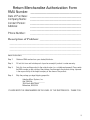
1
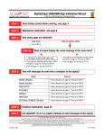
Alpha®
Serial Clock
User Manual
— Make sure DIP switch #8 is set to OFF (see page 17)
© 2008 Adaptive Micro Systems
Document No. 97033006 rev. B
March 24, 2008
1
Copyright © 2008 Adaptive Micro Systems, Inc. All rights reserved.
Adaptive Micro Systems
7840 North 86th Street
Milwaukee, WI 53224 USA
414-357-2020
414-357-2029 (fax)
http://www.adaptivedisplays.com
Adaptive and Alpha are registered trademarks of Adaptive Micro Systems.
AlphaNet plus is a trademark of Adaptive Micro Systems. All other brands
and product names are trademarks or registered trademarks of their
respective companies.
NOTE:Due to continuing product innovation, specifications in this document
are subject to change without notice. The most current release of this manual
is maintained on Adaptive’s website www.adaptivedisplays.com.
2
Contents
Introduction ...........................................................................................................7
Power supply (AC adapter) ....................................................................................7
Master/Slave modes ..............................................................................................8
Setting the time .....................................................................................................9
Bright/Dim switch ..................................................................................................9
Stand alone operation ............................................................................................9
Network configurations—Adding serial clocks to an Alpha network ...................10
Time zone adjust feature ......................................................................................13
Wall mounting .....................................................................................................15
Countertop or desk mounting ..............................................................................15
Using End-of-Line terminators or Ethernet Adapter II devices .............................16
Setting the #5 DIP switch .....................................................................................17
Setting the #8 DIP switch to OFF ..........................................................................17
Clock specifications .............................................................................................18
3
Serial Clock Warranty
Adaptive Micro Systems, Inc. warrants to the original purchaser that the
sign, keyboard and power supply will be free of defects in workmanship and
materials for a period of ninety (90) days from the date of purchase.
Adaptive Micro Systems, Inc. will without charge, repair or replace, at its
option, defective product or component parts upon delivery to the factory
service department accompanied by proof of the date of purchase in the form
of a sales receipt.
This warranty does not apply in the event of any misuse or abuse of the
product, or as a result of any unauthorized repairs or alterations. This
warranty does not apply if the serial number is altered, defaced or removed
from the sign. Incandescent lamps used in incandescent products are not
covered by this warranty.
The purchase price of this product does not include, from Adaptive Micro
Systems, Inc., any on-site support, service or maintenance.
Local ordinances prohibiting the use of flashing signs may exist in some
locations. Compliance with local ordinances is the sole responsibility of the
customer.
To obtain warranty coverage, this product must be registered. Please
complete the enclosed warranty registration card and mail it to Adaptive
Micro Systems, Inc.
How to Obtain Warranty Service on Alpha Products
To obtain warranty service on Alpha products:
1.
Contact the dealer/distributor from whom the product was purchased. If you
do not know where the product was purchased, contact Adaptive Micro
Systems Customer Service at 414-357-2020.
2.
If the dealer/distributor cannot service the product, obtain a Return
Merchandise Authorization (RMA) number through that company. An RMA
number is required to obtain warranty service.
3.
Fill out the Return Merchandise Authorization (RMA) Form on the
following page. To obtain warranty service, this form including the RMA
number must accompany the product.
4.
Follow return instructions on the RMA form to return to Adaptive Micro
Systems, Inc.
4
Return Merchandise Authorization Form
RMA Number: _________________________
Date of Purchase:
Company Name:
Contact Person:
Address:
Phone Number:
________________________________
________________________________
________________________________
________________________________
________________________________
________________________________
Description of Problem: __________________________
_____________________________________________
_____________________________________________
_____________________________________________
_____________________________________________
Return Instructions:
Step 1:
Obtain an RMA number from your dealer/distributor.
Step 2:
Fill out this form and include proof of purchase receipt if product is under warranty.
Step 3:
Pack this form and the product in the original carton (or a suitable replacement). Please write
the RMA number on the outside of the package. Any damage to the product during shipment
is the responsibility of the freight company or the owner of the product.
Step 4:
Ship the package, postage/shipping prepaid to:
Adaptive Micro Systems, Inc.
Attn: RMA No. ___________
7840 North 86th Street
Milwaukee, WI 53224
PLEASE WRITE THE RMA NUMBER ON THE LABEL OF THE SHIPPING BOX - THANK YOU.
5
EMI Compliance
The Alpha serial clock complies with Part 15 of the FCC Rules.
This equipment has been tested and found to comply with the limits for a
Class A digital device, pursuant to Part 15 of the FCC Rules. These are
limits designed to provide reasonable protection against harmful interference
when the equipment is operated in a commercial environment. This
equipment generates, uses and can radiate radio frequency energy and if not
installed and used in accordance with the instruction manual, may cause
harmful interference to radio communications. Operation of this equipment
in a residential area is likely to cause harmful interference in which case the
user will be required to correct the interference at his own expense.
Changes or modifications made to the Alpha serial clock that have not been
expressly approved by Adaptive Micro Systems, Inc. could void your
authority to operate the Alpha serial clock.
NOTE: Damage to clock can occur if exposed to direct sunlight or
moisture. Do not expose clock to direct sunlight or moisture. Clock
is for indoor use only—do not use outdoors.
NOTE: Damage to clock can occur if clock overheats. Make sure that there
is adequate ventilation and air flows on all sides of the clock to
avoid overheating.
Clock has no customer serviceable parts. Return to manufacturer if
service is required.
6
ALPHA Serial Clock Manual
Introduction
The Alpha serial clock displays the time in either 12-hour or 24-hour mode
using a 4-inch LED display. The clock can be used all by itself or it can be
networked with other Alpha clocks or Alpha signs. In a network, one clock
(or a PC attached to the network) is used to synchronize all the other clocks
to the same time.
Used by itself, the Alpha serial clock should be set to master mode. In a
network composed of all Alpha serial clocks, one clock should be set to
master mode and the other clocks set to slave mode. In a network with a PC
that is connected to Alpha clocks and Alpha signs, all the clocks should be
set to slave mode.
Power supply (AC adapter)
The clock is equipped with a small AC adapter with an 18-foot power cord.
Connect the power cord to the adapter plug receptacle on the backside of the
clock (See Figure 1: Serial Clock—Rear Panel) before plugging the adapter
into a standard 120V wall outlet.
6” spacing
Keyhole slot
Keyhole slot
Serial Jacks & DIP switch
(remove screw/plate)
Adapter plug
receptacle
Bright/Dim switch
12/24 Hour switch
Master/Slave switch
Figure 1: Serial Clock—Rear Panel
7
ALPHA Serial Clock Manual
Master/Slave modes
The Alpha serial clock can either operate in master or slave mode. A clock
set to master mode sends out the time once each minute to all of the other
clocks on a network. A clock set to slave mode is ready to receive the time
from the master clock or a PC (personal computer). On a network, only one
clock should be set to master—all other clocks should be set to slave mode.
On a network attached to a PC, all clocks should be set to slave mode.
The master/slave switch is located on the back of the clock, next to the 12/24
hour switch (See Figure 1: Serial Clock—Rear Panel).
To change the master/slave mode settings, first remove the adapter from
the wall outlet, set the master/slave switch to the desired setting, and reinsert the adapter into the wall outlet.
The slave mode setting can also be set using the #5 DIP switch. If the #5 DIP
switch is set to ON, the clock will operate in slave mode, regardless of the
setting of the master/slave switch. If the #5 DIP switch is set to OFF, the
clock will operate in the mode specified by the master/slave switch on the
back of the clock. This DIP switch capability is provided in order to make it
more difficult for unauthorized personnel to change a clock from the slave
mode to the master mode. (See Figure 6: Setting the DIP Switches on page
17 for more information.)
8
ALPHA Serial Clock Manual
Setting the time
HOUR
Button
MINUTE
Button
Figure 2: Serial Clock—Front Panel
To set the time of the master clock, use the HOUR or MINUTE buttons on
the front lower right side of the clock (See Figure 2: Serial Clock—Front
Panel). The HOUR and MINUTE buttons do not operate if the clock is set to
slave mode.
To set the hours, press the HOUR button until the desired number is
displayed. There is no AM/PM option. If the clock is in 12-hour mode, 1-12
will be the only hours displayed. If the clock is in 24-hour mode, 0-23 will
be the hours displayed. Use the 12/24 Hour Switch on the back of the clock
(See Figure 1: Serial Clock—Rear Panel on page 7) to set the clock to either
12-hour or 24-hour mode.
To set the minutes, press the minute button until the desired number is
displayed. Each press of the HOUR or MINUTE button will increase the
number displayed by one. Pressing and holding the HOUR or MINUTE
button down will increase the numbers displayed automatically.
Bright/Dim switch
A bright/dim switch, located on the back of the clock (See Figure 1: Serial
Clock—Rear Panel on page 7), allows you to switch between a bright or a
dim display mode to suit your preference.
Stand alone operation
Clocks not attached to a network must be set to master mode. The time can
be set using the HOUR and MINUTE buttons on the front of the clock.
9
ALPHA Serial Clock Manual
Network configurations—Adding serial clocks to an Alpha network
Alpha serial clocks can be connected together with each other or in a mix of
Alpha signs. Also, like an Alpha sign, an Alpha serial clock must be
terminated when it is the last device on a network.
In a network, one clock (or a PC attached to the network) is used to
synchronize all the other clocks to the same time. In a network composed of
all Alpha serial clocks, one clock must be set to master mode and the other
clocks set to slave mode.
Table 1: Networking Alpha serial clocks
(Example 1 — Clocks on an Ethernet network)
In this example of clocks on an Ethernet network, all clocks must be set to slave mode.
To LEFT
phone jack
B
A
To LEFT
phone jack
C
To LEFT
phone jack
B
A
To LEFT
phone jack
Item
Part #
A
1088-8621
*B
1088-1114B
C
—
Description
3 foot serial cable, RJ-11 to RJ-11
Ethernet Adapter II (5VDC power is required from the clock)
TCP/IP network cable (10/100 BASE-T)
* To provide power to the Ethernet Adapter II, the J5 Jumper must be moved from positions 1 and 2 to positions 2
and 3. To change the location of the J5 jumper go to page 16 for details.
10
ALPHA Serial Clock Manual
Table 2: Networking Alpha serial clocks
(Example 2 — A RS485 network of all clocks)
In this example of an all-clock RS485 network, one of the clocks must be set to master mode. All the other clocks on
the network must be set to slave mode. Also, the first and last clocks on the network must be terminated.
A
To right
phone jack
D
B
C
To either
phone jack
E
To either
phone jack
D
B
A
C
To right
phone jack
Alpha® serial clocks
Item
A
B
C
Part #
Description
1088-9107
End-of-line (EOL) terminator. (An EOL must be plugged into the left—as you face the
back of the clock—RJ11 phone jack). See Using End-of-Line terminators or Ethernet
Adapter II devices on page 16 for details.
—
Ferrite (ferrite end towards sign)
1088-8624
8 foot, 4-conductor RS485 cable
1088-8636
1 foot, 4-conductor RS485 cable
D
4331-0602
Modular Network Adapter
E
1088-8000
RS485 cable
11
ALPHA Serial Clock Manual
In a network with a PC that is connected to Alpha clocks and Alpha signs, all
the clocks must be set to slave mode.
Table 3: Networking Alpha serial clocks
(Example 3 — A network of clocks attached to a PC)
Unlike the previous all-clock network, in this example, a PC is connected to the network. All the clocks on the network
must be set to slave mode. Also, the last clock on the network must be terminated.
A
B
C
D
To either
phone jack
E
Alpha® serial clocks
F
H
PC running
AlphaNET plus™ software
Item
A
B
C
12
To RS485
connector
block
G
To one of the
PC’s COM
(RS232) ports
Set switch to Terminated.
Part #
Description
1088-9107
End-of-line (EOL) terminator. (An EOL must be plugged into the left—as you face the
back of the clock—RJ11 phone jack.)
—
Ferrite (ferrite end towards sign)
1088-8624
8 foot, 4-conductor RS485 cable
1088-8636
1 foot, 4-conductor RS485 cable
D
4331-0602
Modular Network Adapter
E
1088-8000
RS485 cable
F
1088-1111
Converter Box III
G
1088-8634
10 foot, 9 pin-to-9 pin, type “A9” RS232 cable
H
—
serial port DB25-to-DB9 RS232 adapter (may be required by your computer)
ALPHA Serial Clock Manual
Time zone adjust feature
Some Alpha serial clocks have a time zone adjust feature. This lets you
display the time in different time zones on your networked clocks. For
example, you could network four clocks in an office and use them to show
the time across the continental United States. Clocks with this feature do not
have the ability to set a serial address. This feature may not be available on
all Alpha serial clocks.
To set the time zone adjust feature:
1.
Decide which time zone(s) you are going to display. Figure out how
many hours ahead (+) or behind (-) the time zones are from your current
time. This is the number of offset hours. See Table 4: DIP Switch
Settings on page 14 to determine the correct switch settings for switches
numbered 1-4 and 7. For example, if you are in the Central Time Zone
and you wish to display the time in the Eastern Time Zone, the offset
hours would be “+1”. The switch settings would be:
DIP 1 = ON
DIP 2 = OFF
DIP 3 = OFF
DIP 4 = OFF
DIP 7 = OFF
2.
Unplug the adapter from the wall outlet.
3.
Use a Phillips screwdriver to remove the back plate from the serial
clock.
4.
Locate the DIP switches numbered 1-4 and 7. (See
Figure 3: DIP Switches 1-4 and 7).
5.
Use the tip of a pen or small screwdriver to turn the
DIP switches on or off as directed in Table 4 on
page 14.
6.
Reattach the back plate and plug the adapter back
into the wall outlet.
Figure 3: DIP Switches
1-4 and 7
NOTE: If you have a network of only clocks, one clock
must be set to master mode. All the other clocks on the network
must be set to slave mode. If your network of clocks are connected
to a PC, all clocks on the network must be set to slave mode. See
Setting the #5 DIP switch on page 17 for more information.
13
ALPHA Serial Clock Manual
Table 4: DIP Switch Settings
(DIP #8 should always be OFF — see page 17.
To set DIP #5 — see page 17.)
Offset
DIP 1
Hours
14
DIP2
DIP3
DIP4
DIP7
Offset
Hours
DIP 1
DIP2
DIP3
DIP4
DIP7
+0
OFF
OFF
OFF
OFF
OFF
-0
OFF
OFF
OFF
OFF
ON
+1
ON
OFF
OFF
OFF
OFF
-1
ON
OFF
OFF
OFF
ON
+2
OFF
ON
OFF
OFF
OFF
-2
OFF
ON
OFF
OFF
ON
+3
ON
ON
OFF
OFF
OFF
-3
ON
ON
OFF
OFF
ON
+4
OFF
OFF
ON
OFF
OFF
-4
OFF
OFF
ON
OFF
ON
+5
ON
OFF
ON
OFF
OFF
-5
ON
OFF
ON
OFF
ON
+6
OFF
ON
ON
OFF
OFF
-6
OFF
ON
ON
OFF
ON
+7
ON
ON
ON
OFF
OFF
-7
ON
ON
ON
OFF
ON
+8
OFF
OFF
OFF
ON
OFF
-8
OFF
OFF
OFF
ON
ON
+9
ON
OFF
OFF
ON
OFF
-9
ON
OFF
OFF
ON
ON
+10
OFF
ON
OFF
ON
OFF
-10
OFF
ON
OFF
ON
ON
+11
ON
ON
OFF
ON
OFF
-11
ON
ON
OFF
ON
ON
+12
OFF
OFF
ON
ON
OFF
-12
OFF
OFF
ON
ON
ON
+13
ON
OFF
ON
ON
OFF
-13
ON
OFF
ON
ON
ON
+14
OFF
ON
ON
ON
OFF
-14
OFF
ON
ON
ON
ON
+15
ON
ON
ON
ON
OFF
-15
ON
ON
ON
ON
ON
ALPHA Serial Clock Manual
Wall mounting
Plate is flush with
backside of
clock—”feet” are
hidden.
Plate is
reversed—”feet”
are facing out.
Wall Mounting
Countertop Mounting
Figure 4: Serial Clock—Side View
1.
Locate the keyhole slots on the back of the clock, at either end. The slots
are placed six inches apart (See Figure 1: Serial Clock—Rear Panel on
page 7).
2.
Install two #8 screws into the wall/mounting surface, six inches apart.
Use the type of screws and anchoring methods appropriate for the
mounting surface. For example, use wood screws if you are mounting to
a wood surface. (These screws are not supplied.) Make sure that the
heads of the screws are placed at least 3/8 of an inch from the wall.
3.
Insure that the plate and the feet are facing in, towards the backside of
the clock (See Figure 4: Serial Clock—Side View).
4.
Hang the clock on the two screws located on the wall/mounting surface,
using the keyhole slots.
Countertop or desk mounting
1.
Remove the screw and plate on the backside of the clock (See Figure 1:
Serial Clock—Rear Panel on page 7).
2.
Turn the plate over so that the “feet” protrude out (away) from the
backside of the clock (See Figure 4: Serial Clock—Side View). The
plate can be adjusted up or down to obtain the desired viewing angle.
3.
Replace the screw and stand the clock upright.
15
ALPHA Serial Clock Manual
Using End-of-Line terminators or Ethernet Adapter II devices
DIP Switches
J5 Jumper
J5 Jumper—enlarged, side view
12
The EOL Terminator or Ethernet
Adapter II cable must be inserted
into this RJ11 jack.
RJ11 Jacks
3
The J5 jumper must be moved from positions
1 and 2 to positions 2 and 3 when connecting
EOL Terminators or Ethernet Adapter II devices.
Figure 5: Location of DIP Switches and J5 Jumper
End-of-Line (EOL) Terminators help provide stable transmissions across an
RS485 network. Before plugging the EOL Terminator or Ethernet Adapter II
cable into the left RJ11 port on a serial clock, the J5 jumper on the serial
clock needs to be moved. When the J5 jumper is moved to positions 2 and 3,
5VDC is provided to the left RJ11 port on the serial clock.
NOTE: EOL Terminators (p/n 1088-9107) and Ethernet Adapter II (p/n
1088-1114B) must be ordered separately.
To change the location of the J5 jumper
16
1.
Unplug the adapter from the wall outlet. Use a Phillips screwdriver to
remove the back plate from the serial clock.
2.
Locate the J5 jumper on the backside of the serial clock (See Figure 5:
Location of DIP Switches and J5 Jumper).
3.
Use your fingers or a needle-nose pliers to carefully remove the jumper
from positions 1 and 2 (See Figure 5: Location of DIP Switches and J5
Jumper). Make sure not to drop the jumper because it could fall into the
serial clock’s case. Place the jumper into positions 2 and 3.
4.
Reattach the back plate to the serial clock.
5.
The EOL terminator or Ethernet Adapter II cable must be inserted into
the RJ11 port on the left, closest to the DIP switches (See Figure 5:
Location of DIP Switches and J5 Jumper).
6.
Plug the adapter into a 120V outlet.
ALPHA Serial Clock Manual
Setting the #5 DIP switch
#8 DIP Switch
#5 DIP Switch
Figure 6: Setting the DIP Switches
If the #5 DIP Switch is turned on, the clock will operate in slave mode,
regardless of the setting of the master/slave switch.
To change the #5 DIP switch settings:
1.
Unplug the adapter from the wall outlet.
2.
Use a Phillips screwdriver to remove the back plate from the serial
clock.
3.
Locate the #5 DIP switch (See Figure 6: Setting the DIP Switches).
4.
Use the tip of a pen or small screwdriver to turn the DIP switch ON or
OFF. The clock is set to OFF when the clock is shipped from the
manufacturer.
5.
Reattach the back plate to the serial clock.
6.
Plug the adapter into a 120V outlet.
NOTE: Steps 1 and 6 (above) must be done in order for changes to the DIP
switch settings to take effect.
Setting the #8 DIP switch to OFF
If the #8 DIP Switch is turned on, the clock will not operate properly. If #8
DIP switch is on, turn it off this way:
1.
Unplug the adapter from the wall outlet.
2.
Use a Phillips screwdriver to remove the back plate from the serial
clock.
3.
Locate the #8 DIP switch (See Figure 6: Setting the DIP Switches).
4.
Use the tip of a pen or small screwdriver to turn the #8 DIP switch OFF.
5.
Reattach the back plate to the serial clock.
6.
Plug the adapter into a 120V outlet.
NOTE: Steps 1 and 6 (above) must be done in order for changes to the DIP
switch settings to take effect.
17
ALPHA Serial Clock Manual
Clock specifications
Clock Dimensions: 3.5” x 7.1” x 2.2” (34.3 cm x 18.0 cm x 5.6 cm)
Length x Height x Depth
Weight: 1.7 lbs. (0.78 kg) - clock
1.1 lbs. (0.50 kg) - AC adapter
Numeral Height 4” (10.2 cm)
Power: Utilizes 30 Watt transformer, UL Listed, CSA Certified, 120 VAC (transformer
input voltage range is 100-130 VAC)
Battery: Built-in battery backup to 15 days
Serial Interface: Surge Protected, RS485
Network Limitations: 32 drops
4000 feet at 9600 baud
Operating Temperature: 0°C - 49°C (32°F - 120°F)
Humidity: 0% - 95% Non-condensing
Factory Defaults: Slave Mode, 12-hour Mode, Bright Mode
18