1
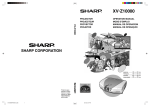
XV-Z10000
XV-Z10000
PROJECTOR
PROJECTEUR
PROYECTOR
PROJETOR
OPERATION MANUAL
MODE D’EMPLOI
MANUAL DE OPERACION
MANUAL DE OPERAÇÃO
SHARP CORPORATION
Printed in Japan
Imprimé au Japon
Impreso en Japón
Impresso no Japão
TINS-A440WJZZA
ENGLISH .............
-1 –
-92
FRANÇAIS ...........
-1 –
-91
ESPAÑOL ............
-1 –
-90
PORTUGUÊS ......
-1 –
-90
This equipment complies with the requirements of Directives 89/336/EEC and 73/23/EEC as amended by
93/68/EEC.
Dieses Gerät entspricht den Anforderungen der EG-Richtlinien 89/336/EWG und 73/23/EWG mit
Änderung 93/68/EWG.
Ce matériel répond aux exigences contenues dans les directives 89/336/CEE et 73/23/CEE modifiées
par la directive 93/68/CEE.
Dit apparaat voldoet aan de eisen van de richtlijnen 89/336/EEG en 73/23/EEG, gewijzigd door 93/68/EEG.
Dette udstyr overholder kravene i direktiv nr. 89/336/EEC og 73/23/EEC med tillæg nr. 93/68/EEC.
Quest’ apparecchio è conforme ai requisiti delle direttive 89/336/EEC e 73/23/EEC, come emendata
dalla direttiva 93/68/EEC.
Este equipamento obedece às exigências das directivas 89/336/CEE e 73/23/CEE, na sua versão
corrigida pela directiva 93/68/CEE.
Este aparato satisface las exigencias de las Directivas 89/336/CEE y 73/23/CEE, modificadas por
medio de la 93/68/CEE.
Denna utrustning uppfyller kraven enligt riktlinjerna 89/336/EEC och 73/23/EEC så som kompletteras av
93/68/EEC.
Dette produktet oppfyller betingelsene i direktivene 89/336/EEC og 73/23/EEC i endringen 93/68/EEC.
Tämä laite täyttää direktiivien 89/336/EEC ja 73/23/EEC vaatimukset, joita on muutettu direktiivillä 93/68/EEC.
SPECIAL NOTE FOR USERS IN THE U.K.
The mains lead of this product is fitted with a non-rewireable (moulded) plug incorporating a 10A fuse.
or
and of the
Should the fuse need to be replaced, a BSI or ASTA approved BS 1362 fuse marked
same rating as above, which is also indicated on the pin face of the plug, must be used.
Always refit the fuse cover after replacing the fuse. Never use the plug without the fuse cover fitted.
In the unlikely event of the socket outlet in your home not being compatible with the plug supplied, cut
off the mains plug and fit an appropriate type.
DANGER:
The fuse from the cut-off plug should be removed and the cut-off plug destroyed immediately and
disposed of in a safe manner.
Under no circumstances should the cut-off plug be inserted elsewhere into a 10A socket outlet, as a
serious electric shock may occur.
To fit an appropriate plug to the mains lead, follow the instructions below:
IMPORTANT:
The wires in the mains lead are coloured in accordance with the following code:
Blue: Neutral
Brown: Live
As the colours of the wires in the mains lead of this product may not correspond with the coloured
markings identifying the terminals in your plug, proceed as follows:
• The wire which is coloured blue must be connected to the plug terminal which is marked N or coloured
black.
• The wire which is coloured brown must be connected to the plug terminal which is marked L or
coloured red.
Ensure that neither the brown nor the blue wire is connected to the earth terminal in your three-pin plug.
Before replacing the plug cover make sure that:
• If the new fitted plug contains a fuse, its value is the same as that removed from the cut-off plug.
• The cord grip is clamped over the sheath of the mains lead, and not simply over the lead wires.
IF YOU HAVE ANY DOUBT, CONSULT A QUALIFIED ELECTRICIAN.
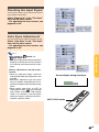
Before using the projector, please read this operation manual carefully.
Introduction
Introduction
ENGLISH
IMPORTANT
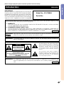
For your assistance in reporting the loss or theft of your
Projector, please record the Serial Number located on
the bottom of the projector and retain this information.
Before recycling the packaging, please be sure that
you have checked the contents of the carton thoroughly
against the list of “Supplied accessories” on page 14.
Model No.: XV-Z10000
Serial No.:
There are two important reasons for prompt warranty registration of your new SHARP Projector, using
the REGISTRATION CARD packed with the projector.
1. WARRANTY
This is to assure that you immediately receive the full benefit of the parts, service and labor
warranty applicable to your purchase.
2. CONSUMER PRODUCT SAFETY ACT
To ensure that you will promptly receive any safety notification of inspection, modification, or
recall that SHARP may be required to give under the 1972 Consumer Product Safety Act, PLEASE
READ CAREFULLY THE IMPORTANT “LIMITED WARRANTY” CLAUSE.
U.S.A. ONLY
WARNING:
High brightness light source. Do not stare into the beam of light, or view directly. Be especially
careful that children do not stare directly into the beam of light.
WARNING: To reduce the risk of fire or electric shock, do not expose this product to
rain or moisture.
See bottom of actual set.
CAUTION
RISK OF ELECTRIC SHOCK.
DO NOT REMOVE SCREWS
EXCEPT SPECIFIED USER
SERVICE SCREWS.
CAUTION: TO REDUCE THE RISK OF ELECTRIC SHOCK,
DO NOT REMOVE COVER.
NO USER-SERVICEABLE PARTS EXCEPT LAMP UNIT.
REFER SERVICING TO QUALIFIED SERVICE
PERSONNEL.
WARNING:
The lightning flash with arrowhead symbol,
within an equilateral triangle, is intended to
alert the user to the presence of uninsulated
“dangerous voltage” within the product’s
enclosure that may be of sufficient magnitude
to constitute a risk or electric shock to
persons.
The exclamation point within a triangle is
intended to alert the user to the presence of
important operating and maintenance
(servicing) instructions in the literature
accompanying the product.
FCC Regulations state that any unauthorized changes or modifications to this equipment not
expressly approved by the manufacturer could void the user’s authority to operate this equipment.
U.S.A. ONLY
-1
INFORMATION
This equipment has been tested and found to comply with the limits for a Class B digital device, pursuant to Part
15 of the FCC Rules. These limits are designed to provide reasonable protection against harmful interference in a
residential installation. This equipment generates, uses, and can radiate radio frequency energy and, if not installed
and used in accordance with the operation manual, may cause harmful interference to radio communications.
However, there is no guarantee that interference will not occur in a particular installation. If this equipment does
cause harmful interference to radio or television reception, which can be determined by turning the equipment off
and on, the user is encouraged to try to correct the interference by one or more of the following measures:
• Reorient or relocate the receiving antenna.
• Increase the separation between the equipment and the receiver.
• Connect the equipment into an outlet on a circuit different from that to which the receiver is connected.
• Consult the dealer or an experienced radio/TV technician for help.
U.S.A. ONLY
Declaration of Conformity
SHARP PROJECTOR, MODEL XV-Z10000
This device complies with Part 15 of the FCC rules. Operation is subject to the following conditions: (1) This device
may not cause harmful interference, and (2) this device must accept any interference received, including interference
that may cause undesired operation.
Responsible Party:
SHARP ELECTRONICS CORPORATION
Sharp Plaza, Mahwah, New Jersey 07430
TEL: 1-800-BE-SHARP (1-800-237-4277)
U.S.A. ONLY
WARNING:
The cooling fan in this projector continues to run for about 90 seconds after the projector is turned off. During
normal operation, when turning the power off always use the power (OFF) button on the projector or on the remote
control. Ensure the cooling fan has stopped before disconnecting the power cord.
DURING NORMAL OPERATION, NEVER TURN THE PROJECTOR OFF BY DISCONNECTING THE POWER CORD.
FAILURE TO OBSERVE THIS WILL RESULT IN PREMATURE LAMP FAILURE.
PRODUCT DISPOSAL
This projector utilizes tin-lead solder, and a pressurized lamp containing a small amount of mercury. Disposal of
these materials may be regulated due to environmental considerations. For disposal or recycling information,
please contact your local authorities or, if you are located in the United States of America, the Electronic Industries
Alliance: www.eiae.org .
Caution Concerning the Lamp Replacement
See “Replacing the Lamp” on pages 76-78.
WARNING:
Some IC chips in this product include confidential and/or trade secret property belonging to Texas Instruments.
Therefore you may not copy, modify, adapt, translate, distribute, reverse engineer, reverse assemble or discompile
the contents thereof.
-2
Outstanding Features
Introduction
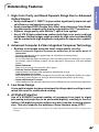
1. High Color Purity and Broad Dynamic Range Due to Advanced
Optical Engine
• Newly developed 12° DMD™ chip provides significantly improved optical efficiency and excellent contrast ratio.
• Newly developed DDR (Double Data Rate) chip eliminates Color Breaking phenomena common with previous generation DLP™ projectors.
• Superior image quality with Minolta™ optical lens system.
• Use of 270 W high-output lamp realizes both high color purity and high
brightness. Natural images made possible by high color reproducibility
can be created with high-brightness and powerful expression capabilities.
2. Advanced Computer & Video lntegrated Composer Technology
• Realizes vivid images using the latest image quality circuitry.
• New I/P conversion algorithm enhances the performance of the motion detect I/P
conversion.
Extensive improvements on the jagged edges or slanted lines in moving images.
• New Edge Up-Scaling
As a result of reducing jaggies and flickering when up-scaling edges of slanted lines, even signals
not reaching a panel resolution of 480I/P can be projected by converting to 720P high-definition
images.
• Noise Reduction
Allows for a clear image even with noisy source signals.
• Contrast Control Dynamic Gamma
Improved contrast and natural color gradation by minimizing hue change.
• Color Management System
Color Management System that freely adjusts only specific hues of RGBCMY enables easy adjustment of only specific locations of an image without affecting other portions of the image.
• Gamma Adjustment Function
Gamma Adjustment Function adds adjustments to each RGB gamma curve for finer image adjustment.
3. Low Noise Design
A new optical engine has been developed for this product resulting in minimized fan noise for undisturbed viewing.
4. All Digital Projection
Use of a DVI/HDCP terminal enables all processes from input to signal
processing and projection to be performed digitally, resulting in the realization of all-digital projection without any data loss due to analog conversion. This also supports the building of home theaters using HTPC*.
* Abbreviation for Home Theater Personal Computer that enables high-definition DVD playback using a personal
computer.
-3
Contents
Introduction
Outstanding Features ......................................... 3
Contents ............................................................... 4
IMPORTANT SAFEGUARDS ............................... 6
How to Access the PDF Operation Manuals of
SharpVision Manager ......................................... 9
Part Names ........................................................ 10
Projector (Front and Top View) ................................ 10
Projector (Rear View) .............................................. 11
Remote Control (Front View) ................................... 12
Remote Control (Top View) ..................................... 12
Using the Remote Control ................................ 13
Available Range of the Remote Control ................. 13
Inserting the Batteries ............................................. 13
Accessories ....................................................... 14
Connections and Setup
Connecting the Projector to Other Devices .... 16
Before Connecting .................................................. 16
Connecting the Power Cord ................................... 16
Connecting to Video Equipment .............................. 17
Connecting the Projector to a Computer ................. 21
Controlling the Projector by a Computer ................. 23
Using as a Wired Remote Control .......................... 24
Setup .................................................................. 25
Using the Adjustment Feet ..................................... 25
Adjusting the Lens .................................................. 26
Using the Lens Shift ................................................ 27
Selecting the HIGH CONTRAST/ HIGH
BRIGHTNESS MODE ........................................... 27
Setting up the Screen .............................................. 28
Screen Size and Projection Distance ...................... 29
Projecting a Reversed/Inverted Image ................... 30
-4
Basic Operation
Setting with the Buttons
Image Projection ............................................... 32
Basic Procedure ...................................................... 32
Selecting the On-screen Display Language ........... 34
Keystone Correction and
Vertical Size Adjustment ............................. 36
Setting with the Menus
Menu Bar Items ................................................. 38
Using the Menu Screen .................................... 40
Menu Selections (Adjustments) .............................. 40
Menu Selections (Settings) ..................................... 42
Adjusting the Picture ........................................ 44
Adjusting Image Preferences .................................. 44
Emphasizing the Contrast ....................................... 45
Selecting the Gamma Position ................................ 45
Selecting the C.M.S. Color ..................................... 45
Progressive Mode .................................................... 46
Picture Setting Function ........................................... 47
Adjusting the Gamma ....................................... 48
Selecting the Gamma Position ................................ 48
Adjusting the Gamma .............................................. 49
Color Management System (C. M. S.) .............. 50
Selecting the Color Reproduction Mode ................. 50
Selecting the Target Color ....................................... 50
Setting the Brightness of the Target Color ............... 51
Setting the Chromatic Value of the Target Color ...... 51
Setting the Hue of the Target Color ........................ 51
Resetting User-Defined Color Settings ................... 52
Overview of All Color Settings ................................. 52
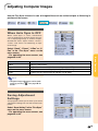
Adjusting Computer Images ............................ 53
When Auto Sync is OFF ........................................... 53
Saving Adjustment Settings ................................... 53
Selecting Adjustment Settings ................................ 54
Special Mode Settings ............................................ 54
Checking the Input Signal ....................................... 55
Auto Sync Adjustment ............................................. 55
Auto Sync Display Function ................................... 56
Selecting the Picture Display Mode ................
Switchable High Contrast/High
Brightness Mode .........................................
Digital Shift Function ........................................
Subtitle Setting ..................................................
Video Digital Noise Reduction
(DNR) System ..............................................
Displaying the Lamp Usage Time ....................
Setting On-screen Display ...............................
Selecting the Signal Type .................................
Setting the Video System .................................
Setting a Background Image ............................
Selecting the Economy Mode ..........................
Introduction
Easy to Use Functions
Appendix
58
61
62
62
63
63
64
65
66
66
67
Setting the Power Save ........................................... 67
RS-232C Off Function .............................................. 67
Automatic Power Off Function ................................. 68
Selecting the Transmission Speed
(RS-232C) ..................................................... 68
Reversing/Inverting Projected Images ............ 69
Displaying the Adjustment Settings ................ 70
Maintenance ......................................................
Cleaning the Ventilative Holes .........................
Maintenance Indicators ....................................
Regarding the Lamp .........................................
72
73
74
76
Lamp ...................................................................... 76
Caution Concerning the Lamp ................................ 76
Replacing the Lamp ................................................ 76
Removing and Installing the Lamp Unit ................. 77
Resetting the Lamp Timer ....................................... 78
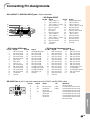
Connecting Pin Assignments ..........................
(RS-232C) Specifications and
Command Settings ......................................
Wired Remote Control Terminal
Specifications ..............................................
Computer Compatibility Chart .........................
Troubleshooting ................................................
For SHARP Assistance (U.S.A only) ...............
Specifications ....................................................
Dimensions ........................................................
Glossary .............................................................
Index ...................................................................
79
80
83
84
85
86
87
88
89
90
-5
IMPORTANT SAFEGUARDS
CAUTION: Please read all of these instructions before you operate this product and save them for
later use.
Electrical energy can perform many useful functions. This product has been engineered and manufactured to
assure your personal safety. BUT IMPROPER USE CAN RESULT IN POTENTIAL ELECTRICAL SHOCK OR
FIRE HAZARDS. In order not to defeat the safeguards incorporated in this product, observe the following basic
rules for its installation, use and servicing.
1. Read Instructions
All the safety and operating instructions should be read
before the product is operated.
2. Retain Instructions
The safety and operating instructions should be
retained for future reference.
3. Heed Warnings
All warnings on the product and in the operating
instructions should be adhered to.
4. Follow Instructions
All operating and use instructions should be followed.
5. Cleaning
Unplug this product from the wall outlet before cleaning.
Do not use liquid cleaners or aerosol cleaners. Use a
damp cloth for cleaning.
6. Attachments
Do not use attachments not recommended by the
product manufacturer as they may cause hazards.
7. Water and Moisture
Do not use this product near water–for example, near
a bath tub, wash bowl, kitchen sink, or laundry tub; in a
wet basement; or near a swimming pool; and the like.
8. Accessories
Do not place this product on an unstable cart, stand,
tripod, bracket, or table. The product may fall, causing
serious injury to a child or adult, and serious damage
to the product. Use only with a cart, stand, tripod,
bracket, or table recommended by the manufacturer,
or sold with the product. Any mounting of the product
should follow the manufacturer’s instructions, and
should use a mounting accessory recommended by
the manufacturer.
9. Transportation
A product and cart combination
should be moved with care. Quick
stops, excessive force, and
uneven surfaces may cause the
product and cart combination to
overturn.
10.Ventilation
Slots and openings in the cabinet are provided for
ventilation to ensure reliable operation of the product
and to protect it from overheating, and these openings
must not be blocked or covered. The openings should
never be blocked by placing the product on a bed,
sofa, rug, or other similar surface. This product should
not be placed in a built-in installation such as a bookcase or rack unless proper ventilation is provided or
the manufacturer’s instructions have been adhered to.
-6
11. Power Sources
This product should be operated only from the type of
power source indicated on the marking label. If you
are not sure of the type of power supply to your home,
consult your product dealer or local power company.
For products intended to operate from battery power,
or other sources, refer to the operating instructions.
12. Grounding or Polarization
This product is equipped with a three-wire groundingtype plug, a plug having a third (grounding) pin. This
plug will only fit into a grounding-type power outlet. This
is a safety feature. If you are unable to insert the plug
into the outlet, contact your electrician to replace your
obsolete outlet. Do not defeat the safety purpose of
the grounding-type plug.
13. Power-Cord Protection
Power-supply cords should be routed so that they are
not likely to be walked on or pinched by items placed
upon or against them, paying particular attention to
cords at plugs, convenience receptacles, and the point
where they exit from the product.
14. Lightning
For added protection for this product during a lightning
storm, or when it is left unattended and unused for long
periods of time, unplug it from the wall outlet and
disconnect the cable system. This will prevent damage
to the product due to lightning and power-line surges.
15. Overloading
Do not overload wall outlets, extension cords, or integral
convenience receptacles as this can result in a risk of
fire or electric shock.
16. Object and Liquid Entry
Never push objects of any kind into this product through
openings as they may touch dangerous voltage points
or short-out parts that could result in a fire or electric
shock. Never spill liquid of any kind on the product.
17. Servicing
Do not attempt to service this product yourself as
opening or removing covers may expose you to dangerous voltage or other hazards. Refer all servicing to
qualified service personnel.
Introduction
19. Replacement Parts
18. Damage Requiring Service
Unplug this product from the wall outlet and refer
servicing to qualified service personnel under the
following conditions:
a. When the power-supply cord or plug is damaged.
b. If liquid has been spilled, or objects have fallen
into the product.
c. If the product has been exposed to rain or water.
d. If the product does not operate normally by
following the operating instructions. Adjust only
those controls that are covered by the operating
instructions, as an improper adjustment of other
controls may result in damage and will often
require extensive work by a qualified technician
to restore the product to normal operation.
e. If the product has been dropped or damaged in
any way.
f. When the product exhibits a distinct change in
performance.
When replacement parts are required, be sure the
service technician has used replacement parts
specified by the manufacturer or have the same
characteristics as the original part. Unauthorized
substitutions may result in fire, electric shock, or other
hazards.
20. Safety Check
Upon completion of any service or repairs to this
product, ask the service technician to perform safety
checks to determine that the product is in proper
operating condition.
21. Wall or Ceiling Mounting
This product should be mounted to a wall or ceiling
only as recommended by the manufacturer.
22. Heat
This product should be situated away from heat sources
such as radiators, heat registers, stoves, or other
products (including amplifiers) that produce heat.
INTELLECTUAL PROPERTY RIGHTS
IMPORTANT
READ BEFORE USING THE PRODUCT
• Digital Light Processing, DLP, Digital Micromirror Device and DMD are trademarks of Texas Instruments.
• Microsoft and Windows are registered trademarks of Microsoft Corporation in the United States and/or
other countries.
• PC/AT is a registered trademark of International Business Machines Corporation in the United States.
• Adobe Acrobat is a trademark of Adobe Systems Incorporated.
• Macintosh is a registered trademark of Apple Computer, Inc. in the United States and/or other countries.
• Minolta is a registered trademark of Minolta Co., Ltd.
• All other company or product names are trademarks or registered trademarks of their respective companies.
-7
IMPORTANT SAFEGUARDS
Be sure to read the following safeguards when setting up
your projector.
Caution concerning the lamp unit
■ Potential hazard of glass particles if
lamp ruptures. In case of lamp rupture,
contact your nearest Authorized
SharpVision Service Center or Dealer
for replacement.
See “Replacing the Lamp” on pages 76-78.
CAUTION
PRECAUCIÓN
PRÉCAUTION
BQC-XVZ100001
Cautions concerning the setup of the projector
■ For minimal servicing and to maintain high image quality, SHARP recommends that this projector be installed
in an area free from humidity, dust and cigarette smoke.
When the projector is subjected to these environments,
the lens must be cleaned more often. As long as the
projector is regularly cleaned, use in these environments will not reduce the overall operation life of the
unit. Internal cleaning should only be performed by an
Authorized SharpVision Service Center or Dealer.
Do not set up the projector in places exposed to
direct sunlight or bright light.
■ Be sure that the intake vent and the exhaust vent are
not obstructed.
■ If the cooling fan becomes obstructed, a protection circuit will automatically turn off the projector. This does
not indicate a malfunction. Remove the projector power
cord from the wall outlet and wait at least 10 minutes.
Place the projector where the intake and exhaust vents
are not blocked, plug the power cord back in and turn
on the projector. This will return the projector to the
normal operating condition.
Cautions regarding the transportation of the projector
■ When transporting the projector, be sure not to subject
it to hard impact and/or vibration, as this can result in
damage. Take extra caution with the lens. Before moving the projector, be sure to unplug the power cord from
the wall outlet, and disconnect any other cables connected to it.
Other connected equipment
■ Position the screen so that it is not in direct sunlight or
room light. Light falling directly on the screen washes
out the colors, making viewing difficult. Close the curtains and dim the lights when setting up the screen in a
sunny or bright room.
■ When connecting other audio-visual equipment or a
computer to the projector, make the connections AFTER turning off the projector and the equipment to be
connected.
■ Please read the operation manuals of the projector and
the equipment to be connected for instructions on how
to make the connections.
The projector may safely be tilted to a maximum
angle of 5 degrees.
Temperature monitor function
■ Placement should be within ±5 degrees.
Do not subject the projector to hard impact and/
or vibration.
■ Take care with the lens so as not to hit or damage the
surface of the lens.
Rest your eyes occasionally.
■ Watching the screen for long hours continuously will
make your eyes tired. Be sure to occasionally rest your
eyes.
Avoid locations with high or low temperature.
■ The operating temperature for the projector is from 41°F
to 95°F (+5°C to +35°C).
■ The storage temperature for the projector is from
–4°F to 140°F (–20°C to +60°C).
Do not block the intake and exhaust vents.
■ Allow at least 11.8" (30 cm) of space between the exhaust vent and the nearest wall or obstruction.
-8
■ If the projector starts to overheat
due to setup problems or blockage
of the air vents, “
” and
“
” will blink in the lower left
corner of the picture. If the temperature continues to rise, the lamp will turn off, the
temperature warning indicator on the projector will blink,
and after a 90-second cooling-off period the power will
shut off. Refer to “Maintenance Indicators” on page 74
for details.
Info
• The cooling fan regulates the internal temperature, and
its performance is automatically controlled. The sound
of the fan may change during projector operation due
to changes in the fan speed. This does not indicate
malfunction.
• Do not unplug the power cord during projection or cooling fan operation. This can create damage due to the
rise in internal temperature, as the cooling fan also
stops.
Introduction
How to Access the PDF Operation Manuals of
SharpVision Manager
PDF operation manuals in several languages for the “SharpVision Manager” theater projector software provided are included in the CD-ROM. To utilize these manuals, you need Adobe
Acrobat Reader installed on your PC (Windows or Macintosh). If you have not installed Acrobat Reader yet, you can install it from the CD-ROM.
To install Acrobat Reader from the CD-ROM
For Windows:
1 Insert the CD-ROM in the CD-ROM drive.
2 Double click the “My Computer” icon.
3 Double click the “CD-ROM” drive.
4 Double click the “ACROBAT” folder.
5 Double click the language (name of the folder)
that you want to view.
6 Double click the installation program and
follow the instructions on the screen.
For Macintosh:
1 Insert the CD-ROM in the CD-ROM drive.
2 Double click the “CD-ROM” icon.
3 Double click the “ACROBAT” folder.
4 Double click the language (name of the folder)
that you want to view.
5 Double click the installation program and
follow the instructions on the screen.
For other operating systems:
Please download Acrobat Reader from the Internet (http://www.adobe.com).
For other languages:
If you prefer using Acrobat Reader for languages other than those included in the CD-ROM, please
download the appropriate version from the Internet.
Accessing the PDF Manuals
For Windows:
1 Insert the CD-ROM in the CD-ROM drive.
2 Double click the “My Computer” icon.
3 Double click the “CD-ROM” drive.
4 Double click the “MANUALS” folder.
5 Double click the language (name of the
folder) that you want to view.
6 Double click the “SVM2” pdf file to access the
SharpVision Manager manual.
For Macintosh:
1 Insert the CD-ROM in the CD-ROM drive.
2 Double click the “CD-ROM” icon.
3 Double click the “MANUALS” folder.
4 Double click the language (name of the
folder) that you want to view.
5 Double click the “SVM2” pdf file to access the
SharpVision Manager manual.
Note
• If the desired pdf file cannot be opened by double clicking the mouse, start Acrobat Reader first, then
specify the desired file using the “File”, “Open” menu.
• See the “readme.txt” file on the CD-ROM for important information not included in this operation manual.
-9
Part Names
Numbers in
refer to the main pages in this operation manual where the topic is explained.
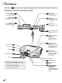
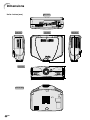
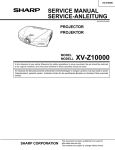
Projector (Front and Top View)
Adjustment buttons
(", ', \, |)
32
32
For displaying adjustment
and setting screens.
For selecting menu items.
ENTER button
32
For setting items selected
or adjusted on the menu.
UNDO button
MENU button
58
RESIZE button
For switching the screen
size (SIDE BAR, SMART
STRETCH, etc.).
32
INPUT button
37
For undoing an operation or
returning to the default
settings.
For switching input mode
1, 2, 3, 4 or 5.
32
Power (ON/OFF) buttons
For turning the power on
or off.
74
Temperature warning
indicator
When the internal
temperature rises, this
indicator will illuminate
red.
74
Lens shift dial
27
Zoom knob
26
Focus ring
26
Illuminates blue, indicating
normal function. Replace
the lamp when the
indicator illuminates red.
32
Adjustment foot
Lamp replacement
indicator
Power indicator
Illuminates red, when the
projector is in standby.
When the power is turned
on, this indicator will
illuminate blue.
25
Lens cap
Intake vent
Attaching and removing the lens cap
• Press on the two buttons of the lens cap
and attach it on the lens. Then release
the buttons to lock it in place.
• Press on the two buttons of the lens cap
and remove it from the lens.
-10
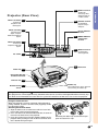
25
Adjustment foot
13
Remote control
sensor
61
HIGH CONTRAST/
HIGH BRIGHTNESS
MODE button
For switching between
“HIGH CONTRAST MODE”
and “HIGH BRIGHTNESS
MODE”.
17
18
23
Terminals for
component and
RGB signals.
INPUT 5 terminal
For controlling
projector using a
computer.
19
DC 12V OUTPUT
terminal
Terminal for DVI
digital, computer
RGB and component
signals.
INPUT 2 terminals
RS-232C terminal
24
WIRED REMOTE
control input
terminal
17
INPUT 4 terminal
18
Terminals for
component and RGB
signals.
AC socket
For connecting
video equipment.
16
73
Intake vent
Intake vent
73
Kensington Security
Standard connector
Exhaust vent
73
Remote control
sensor
13
Rubber cap
The terminal cover can be attached
after removing the rubber cap.
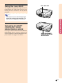
Using the Kensington Lock
This projector has a Kensington Security Standard connector for use with a Kensington MicroSaver Security System. Refer to the information that came with the system for instructions on how to use it to secure the projector.
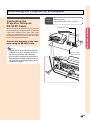
Using the Terminal Cover
When the projector is used on a desktop, high mounted or
ceiling mounted, attach the terminal cover (supplied) to hide
the connecting cables.
Attaching the Terminal Cover
1 Align the hook on the terminal cover with the insert hole
in the hook at the back of the projector.
2 Press the hook in the direction indicated with the arrow to
fasten the terminal cover to the projector.
3 Insert the terminal cover into the mounting groove on the
projector while pushing the tabs inside the terminal cover
to the outside with your fingers.
PUSH!
3
3
1
2
1
Removing the rubber cap attached on the projector and attach the clips.
-11
Introduction
Terminal for
connecting video
equipment with an
S-video terminal.
Projector (Rear View)
INPUT 1 terminals
INPUT 3 terminal
Part Names
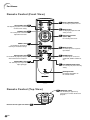
Remote Control (Front View)
32
KEYSTONE button
For turning the power on or off.
36
For adjusting Keystone Correction
or Vertical Size setting.
ENTER button
Power (ON/OFF) buttons
32
MENU button
For displaying adjustment and
setting screens.
32
For setting items selected or
adjusted on the menu.
32
Adjustment buttons
(', ", \, |)
For selecting menu items.
UNDO button
37
For undoing an operation or
returning to the default settings.
32
INPUT buttons
For switching to the respective
input modes.
AUTO SYNC button
55
58
For automatically adjusting images
when connected to a computer.
RGB/COMP. button
RESIZE button
For switching the screen size
(SIDE BAR, SMART STRETCH,
etc.).
65
For switching to the respective
input signal type.
47
PICTURE SETTING button
For selecting the picture memory
setting.
Backlight button
For lighting all buttons on
the remote control.
Remote Control (Top View)
24
WIRED R/C JACK
For controlling the projector by
connecting the remote control to the
projector.
Remote control signal transmitters
-12
13
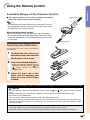
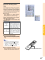
Using the Remote Control
Introduction
Available Range of the Remote Control
■ The remote control can be used to control the projector
within the ranges shown in the illustration.
Remote control
23'(7 m)
Note
• The signal from the remote control can be reflected off a screen
for easy operation. However, the effective distance of the signal
may differ due to the screen material.
45˚
30˚
30˚
When using the remote control:
• Be sure not to drop, expose to moisture or high temperature.
• The remote control may malfunction under a fluorescent lamp.
Under that circumstance, move the projector away from the fluorescent lamp.
45˚
30˚
Remote control
Inserting the Batteries
The batteries (two “AA” size) are included in
the package.
1
Pull down the tab on the cover
and remove the cover towards
the direction of the arrow.
2
Insert the included batteries.
3
Insert the lower tab of the
cover into the opening, and
lower the cover until it clicks
in place.
• Insert the batteries making sure the
and
polarities correctly match the
marks inside the batter y
compartment.
Incorrect use of the batteries may cause them to leak or explode. Please follow the precautions below.
Caution
• Insert the batteries making sure the polarities correctly match the
and
marks inside the battery compartment.
• Batteries of different types have different properties, therefore do not mix batteries of different types.
• Do not mix new and old batteries.
This may shorten the life of new batteries or may cause old batteries to leak.
• Remove the batteries from the remote control once they have run out, as leaving them can cause them to leak.
Battery fluid from leaked batteries is harmful to your skin, therefore be sure to first wipe them and then remove
them using a cloth.
• The batteries included with this projector may exhaust over a short period, depending on how they are kept.
Be sure to replace them as soon as possible with new batteries when they have run out.
• Remove the batteries from the remote control if you will not be using the remote control for a long time.
-13
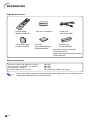
Accessories
Supplied accessories
Remote control
RRMCGA128WJSA
Lens cap (attached)
PCAPH1056CESA
Two “AA” size batteries
CD-ROM
(SharpVision Manager)
UDSKAA028WJN1
Power cord
CACCDA010DE01
Terminal cover
CCOVA1985CE02
Operation manual (this manual)
TINS-A440WJZZA
SharpVision Manager operation manual
TINS-A452WJZZ
Optional accessories
3 RCA to 15-pin D-sub cable (9'10'' (3.0m))
DVI to 15-pin D-sub adaptor (7.9'' (20cm))
DVI cable (9'10'' (3.0m))
RS-232C cable (32'10'' (10.0m))
Note
-14
AN-C3CP
AN-A1DV
AN-C3DV
AN-C10RS (null modem, cross type)
• Some of the cables may not be available depending on the region. Please check with your nearest
Authorized SharpVision Service Center or Dealer.
Connections and Setup
Connections and Setup
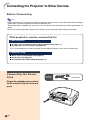
Connecting the Projector to Other Devices
Before Connecting
Note
• Before connecting, be sure to turn off both the projector and the devices to be connected. After making all
connections, turn on the projector and then the other devices.
When connecting a computer, be sure that it is the last device to be turned on after all the connections are
made.
• Be sure to read the operation manuals of the devices to be connected before making connections.
This projector can be connected to:
Video equipment:
■ A VCR, Laser disc player or other video equipment (See page 17.)
■ A DVD player or DTV* decoder (See page 18.)
*DTV is the umbrella term used to describe the new digital television system in the United States.
A computer using:
■ DVI to 15-Pin D-sub adapter (See page 21.)
■ A DVI cable (See page 22.)
■ An RS-232C cable (AN-C10RS) (See page 23.)
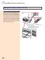
Connecting the Power
Cord
Plug in the supplied power cord into
the AC socket on the rear of the projector.
-16
Supplied
accessory
Power cord
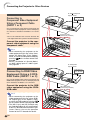
Connecting to Video Equipment
Connecting to Video
Equipment Using an
S-video or a Composite
Video Cable
VCR or other video equipment
To S-video output terminal
To video output terminal
Connections and Setup
Using an S-video or a composite video cable,
a VCR, laser disc player or other video equipment can be connected to INPUT 3 and INPUT
4 input terminals.
Connect the projector to the video
equipment using an S-video cable
or a composite video cable (both
commercially available).
Note
• The INPUT 3 (S-VIDEO) terminal uses a
video signal system in which the picture
is separated into color and luminance signals to realize a higher-quality image. To
view a higher-quality image, use a commercially available S-video cable to connect the INPUT 3 terminal on the projector and the S-video output terminal on the
video equipment.
Composite video cable
(commercially available)
S-video cable (commercially available)
-17
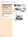
Connecting the Projector to Other Devices
To analog component
output terminal
Connecting to
Component Video Equipment
Using a Component Cable
(INPUT 1 or 2)
Use a component cable when connecting the
component video equipment such as DVD players and DTV* decoders to INPUT 1 or 2 terminal.
* DTV is the umbrella term used to describe the
new digital television system in the United States.
DVD player or
DTV* decoder
Component cable
(commercially available)
Connect the projector to the component video equipment using the
component cable.
Note
• When connecting the projector to the
video equipment in this way, select “Component” for “Signal Type” in the “Options”
menu, or select the Component mode by
on the remote control. See
pressing
page 65.
• Set the “Resolution” of “Special Modes”
to “480P” during input of a 480P signal.
See page 54.
To analog RGB
output terminal
DVD player or
DTV* decoder
Connecting to RGB Video
Equipment Using a 5 RCA
RGB Cable (INPUT 1 or 2)
Use a 5 RCA RGB cable when connecting the
RGB video equipment such as DVD players and
DTV* decoders to INPUT 1 or 2 terminal.
Connect the projector to the RGB
video equipment using the 5RCA
RGB cable.
Note
• When connecting the projector to the
video equipment in this way, select “RGB”
for “Signal Type” in the “Options” menu,
or select the RGB mode by pressing
on the remote control. See page 65.
• The (HD/C sync) and (VD) terminals may
be used depending on the specifications
of the DTV decoder connected to this projector. Please refer to the operation
manual of the DTV decoder for details.
-18
5 RCA RGB cable
(Commercially available)
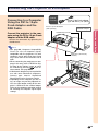
Connecting to Component Video Equipment
Using a 3 RCA to 15-pin
D-Sub Cable and the
DVI to 15-pin D-Sub
adaptor (INPUT 5)
Optional
accessories
DVI to 15-pin
D-sub adaptor
Type: AN-A1DV
(7.9" (20 cm))
DVI to 15-pin
D-sub adaptor
(sold
separately)
To analog component
output terminal
Connections and Setup
Use a 3 RCA to 15-pin D-Sub cable and the
DVI to 15-pin D-Sub adaptor when connecting
to the INPUT 5 terminal, component video
equipment such as DVD players and DTV* decoders.
3 RCA to 15-pin
D-sub cable
Type: AN-C3CP
(9'10" (3.0 m))
* DTV is the umbrella term used to describe the
new digital television system in the United States.
Connect the projector to the video
equipment using a 3 RCA to 15-pin
D-Sub cable and the DVI to 15-pin
D-Sub adaptor.
3 RCA to 15-pin
D-sub cable
(sold separately)
DVD player or
DTV* decoder
Note
• Select the input signal type of the video
equipment. See page 65.
-19
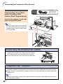
Connecting the Projector to Other Devices
Connecting to Video
Equipment with the DVI
Output Terminal Using
the DVI Cable
Optional
accessory
DVD player or
DTV* decoder
Use the DVI cable when connecting to the INPUT 5 terminal, video equipment with the DVI
output terminal such as DVD players and DTV*
decoders.
* DTV is the umbrella term used to describe the
new digital television system in the United States.
Connect the projector to the video
equipment using the DVI cable.
Note
• Select the input signal type of the video
equipment. See page 65.
-20
DVI cable
Type:AN-C3DV
(9'10'' (3.0m))
DVI cable
(sold separately)
Connecting the Projector to a Computer
Connecting to a Computer
Using the DVI to 15-pin
D-sub Adaptor and the
RGB Cable
DVI to 15-pin D-sub adaptor
Type: AN-A1DV (7.9" (20cm))
DVI to 15-pin D-sub adaptor
(sold separately)
Notebook computer
Connections and Setup
Connect the projector to the computer using the DVI to 15-pin D-sub
adaptor and the RGB cable.
Optional
accessory
To RGB output terminal
• Secure the connectors by tightening the
thumbscrews.
Note
• See page 84 “Computer Compatibility
Chart” for a list of computer signals
compatible with the projector. Use with
computer signals other than those listed
may cause some of the functions not to
work.
• When connecting the projector to a computer in this way, select “A.RGB” for “Signal Type” in the “Options” menu, or select
on the rethe “A.RGB” by pressing
mote control. See page 65.
• A Macintosh adaptor may be required for
use with some Macintosh computers.
Contact your nearest Authorized
SharpVision Service Center or Dealer.
• Depending on the computer you are using, an image may not be projected unless the signal output setting of the computer is switched to the external output.
Refer to the computer operation manual
for switching the computer signal output
settings.
RGB Cable (commercially
available)
-21
Connecting the Projector to Other Devices
DVI cable
Type:AN-C3DV
(9'10'' (3.0m))
Optional
accessory
Connecting to a Computer Using a DVI
Cable (Sold Separately)
To DVI Digital output terminal
Desktop computer
Connect the projector to the computer using the DVI cable.
Note
• Switch the signal type to either “A.RGB”
or “D.PC RGB” depending on whether the
computer output signal is analog or digital. See page 65.
DVI cable
(sold separately)
Connecting the thumbscrew cables
■ Connect the thumbscrew cable making sure that it fits correctly into the terminal. Then, firmly secure the connectors by tightening the screws on both sides of the plug.
■ Do not remove the ferrite core attached to the RGB cable.
Ferrite core
“Plug and Play” function
■ This projector is compatible with VESA-standard DDC 1/DDC 2B. The projector and a VESA DDC
compatible computer will communicate their setting requirements, allowing for quick and easy setup.
■ Before using the “Plug and Play” function, be sure to turn on the projector first and the connected
computer last.
Note
• The DDC “Plug and Play” function of this projector operates only when used in conjunction with a VESA
DDC compatible computer.
-22
Controlling the Projector by a Computer
Controlling the
Projector Using an
RS-232C Cable
To RS-232C terminal
Connections and Setup
When the RS-232C terminal on the projector
is connected to a computer with an RS-232C
cable (null modem, cross type, sold separately), the computer can be used to control
the projector and check the status of the projector. See page 80 for details.
RS-232C cable
Optional
accessory Type: AN-C10RS (32'10'' (10.0m))
Desktop computer
Connect the projector to the computer using an RS-232C cable.
Note
• Do not connect or disconnect an RS-232C
cable to or from the computer while it is
on. This may damage your computer.
• The RS-232C function may not operate if
your computer terminal is not correctly set
up. Refer to the operation manual of the
computer for details.
RS-232C cable
(sold separately)
-23
Connecting the Projector to Other Devices
Using as a Wired Remote Control
Connecting the Remote
Control to the Projector
WIRED REMOTE control input
terminal
When the remote control cannot be used due
to the range or positioning of the projector
(rear projection, etc.), connect a ø3.5 mm
minijack cable (commercially available or
available as Sharp service part QCNW4870CEZZ) from the WIRED R/C JACK on the
top of the remote control to the WIRED REMOTE control input terminal.
To WIRED R/C JACK
ø3.5 mm minijack cable
(commercially available or available as
Sharp service part QCNW-4870CEZZ)
-24
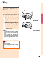
Setup
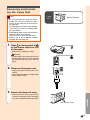
Using the Adjustment
Feet
1
2
Press the foot releases and lift
the projector to the desired
angle.
Connections and Setup
The height of the projector can be adjusted
using the adjustment feet when the projector
is placed on an uneven surface or when the
screen is slanted.
The position of the projected image can be
made higher by adjusting the projector when
it is in a location lower than the screen.
Foot releases
Remove your hands from the
foot releases. Once the adjustment feet have locked in position, release the projector.
• If the screen is at an angle, the adjustment feet can be used to adjust the
angle of the image.
Note
Adjustment feet
• The projector is adjustable up to approximately 5 degrees from the standard position.
• When the height of the projector is adjusted, the image may become distorted
(keystoned), depending on the relative
positions of the projector and the screen.
See page 36 for details on the keystone
correction.
Info
• Do not hold the lens when lifting or lowering the projector.
• When lowering the projector, be careful
not to get your finger caught in the area
between the adjustment foot and the
projector.
-25
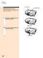
Setup
Focus ring
Zoom knob
Adjusting the Lens
The image is focused and adjusted to the
desired size using the focus ring or zoom
knob on the projector.
1
Zooming is adjusted by moving the zoom knob.
Zoo
m in
ut
mo
Zoo
Zoom Knob
2
The focus is adjusted by rotating the focus ring.
Focus ring
-26
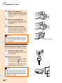
Using the Lens Shift
The height of the projected image can be adjusted within the shift range of the lens by
rotating the lens shift dial on the top of the
projector.
Lens shift dial
Up
n
Dow
Note
Connections and Setup
• Do not turn the lens shift dial beyond the
upper limit and lower limit positions. This
may cause the projector to malfunction.
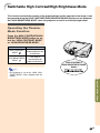
Selecting the HIGH
CONTRAST/ HIGH
BRIGHTNESS MODE
Pressing the HIGH CONTRAST/HIGH BRIGHTNESS MODE button switches between the
contrast emphasis mode and brightness emphasis mode. See page 61 for details.
HIGH CONTRAST/
HIGH BRIGHTNESS
MODE button
-27
Setup
Setting up the Screen
Position the projector perpendicular to the screen with all feet flat and level to achieve an optimal image.
Note
• The projector lens should be centered in the middle of the screen. If the horizontal line passing through the
lens center is not perpendicular to the screen, the image will be distorted, making viewing difficult.
• For optimal image, position the screen so that it is not in direct sunlight or room light. Light falling directly on
the screen washes out the colors, making viewing difficult. Close the curtains and dim the lights when
setting up the screen in a sunny or bright room.
• A polarizing screen cannot be used with this projector.
Standard Setup (Front Projection)
■ Place the projector at the required distance from the screenaccording to the desired picture size. (See page
29.)
Screen size : 100 inches (254cm)
Aspect ratio : 16:9
Example of Standard Setup
• The distance from the screen to the projector
Side View
may vary depending on the size of the screen.
P.29
90°
• The default setting can be used, when placing the
Audience
Top View
projector in front of the screen. If the projected image is reversed or inverted, readjust the setting to
“Front” for “PRJ Mode” in the “Options” menu.
P.69
• Place the projector so that an imaginary horizontal
90°
-28
line that passes through the center of the lens is
perpendicular to the screen.
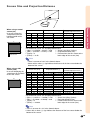
Screen Size and Projection Distance
x
y
4
3
: Screen area
: Picture area
Screen size (4:3)
Diag. (x)
250"
200"
150"
100"
84"
72"
60"
Width
200"
160"
120"
80"
67"
58"
48"
Height
150"
120"
90"
60"
50"
43"
36"
Projection distance (y)
Maximum (y1)
41'4" (12.6 m)
33' (10.1 m)
24'9" (7.5 m)
16'5" (5.0 m)
13'9" (4.2 m)
11'10" (3.6 m)
9'10" (3.0 m)
Minimum (y2)
30'6" (9.3 m)
24'4" (7.4 m)
18'3" (5.6 m)
12'1" (3.7 m)
10'2" (3.1 m)
8'8" (2.6 m)
7'2" (2.2 m)
Connections and Setup
When using a normal
screen (4:3)
In case of setting the
16:9 picture to the full
horizontal width of the
4:3 screen.
z
Distance from the lens center to
the lower edge of the screen (z)
Upper (z1)
Lower (z2)
0" (0 cm)
–12'6" (–286 cm)
0" (0 cm)
–10' (–229 cm)
0" (0 cm)
–7'6" (–171 cm)
0" (0 cm)
–5' (–114 cm)
0" (0 cm)
–4'2" (–96 cm)
0" (0 cm)
–3'7" (–82 cm)
0" (0 cm)
–3' (–69 cm)
The formula for screen size and projection distance
x : Screen size (diag.) (inches)
y1 (Max.) = (0.05058x – 0.0447) × 3.28
y2 (Min.) = (0.03734x – 0.0447) × 3.28
y : Projection distance (feet)
z1 (Upper) = 0
z : Distance from the lens center to the
z2 (Lower) = –0.45x
lower edge of the screen (feet)
Note
• There is an error of ±3% in the formula above.
• Values with a minus (–) sign indicate the distance of the lens center below the
bottom of the screen.
When using a wide
Screen size (16:9)
Projection distance (y)
screen (16:9)
In case of displaying the Diag. (x) Width Height Maximum (y ) Minimum (y )
1
2
16:9 picture on the whole
300"
261"
147"
54'1" (16.5 m) 39'11" (12.2 m)
of the 16:9 screen.
250"
218"
123"
45'1" (13.7 m) 33'3" (10.1 m)
16
9
: Picture area
200"
150"
133"
106"
100"
92"
84"
72"
60"
40"
174"
131"
116"
92"
87"
80"
73"
63"
52"
35"
98"
74"
65"
52"
49"
45"
41"
35"
29"
20"
36' (11.0 m)
26'12" (8.2 m)
23'11" (7.3 m)
18'11" (5.8 m)
17'11" (5.5 m)
16'5" (5.0 m)
15' (4.6 m)
12'10" (3.9 m)
10'8" (3.3 m)
7'1" (2.2 m)
26'7" (8.1 m)
19'11" (6.1 m)
17'7" (5.4 m)
13'11" (4.3 m)
13'2" (4.0 m)
12'1" (3.7 m)
11'1" (3.4 m)
9'6" (2.9 m)
7'10" (2.4 m)
5'2" (1.6 m)
Distance from the lens center to
the lower edge of the screen (z)
Upper (z1)
Lower (z2)
0" (0 cm)
–12'3" (–374 cm)
0" (0 cm)
–10'3" (–311 cm)
0" (0 cm)
–8'2" (–249 cm)
0" (0 cm)
–6'2" (–187 cm)
0" (0 cm)
–5'5" (–166 cm)
0" (0 cm)
–4'4" (–131 cm)
0" (0 cm)
–4'1" (–125 cm)
0" (0 cm)
–3'9" (–114 cm)
0" (0 cm)
–3'5" (–105 cm)
0" (0 cm)
–2'11" (–90 cm)
0" (0 cm)
–2'5" (–75 cm)
0" (0 cm)
–1'8" (–50 cm)
The formula for screen size and projection distance
x : Screen size (diag.) (inches)
y1 (Max.) = (0.05510x – 0.04593) × 3.28
y : Projection distance (feet)
y2 (Min.) = (0.04068x – 0.04369) × 3.28
z1 (Upper) = 0
z : Distance from the lens center to the
lower edge of the screen (feet)
z2 (Lower) = –0.4904x
Note
• There is an error of ± 3% in the formula above.
• Values with a minus (–) sign indicate the distance of the lens center below the
bottom of the screen.
-29
Setup
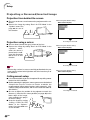
Projecting a Reversed/Inverted Image
Projection from behind the screen
■ Place a translucent screen between the projector and the audience.
■ Reverse the image by setting “Rear” for “PRJ Mode” in the
“Options” menu. See
page 69 for use of
this function.
Projection using a mirror
■ Place a mirror (normal flat type) in front of the lens.
■ Reverse the image by setting “Rear” for “PRJ Mode” in the
“Options” menu,
when the mirror is
placed on the audience side. See page
69 for use of this
function.
Info
• When using a mirror, be sure to carefully position both the projector and the mirror so the light does not shine into the eyes of
the audience.
When using the default setting.
▼On-screen Display
The image is reversed.
When using the default setting.
▼On-screen Display
The image is reversed.
When using the default setting.
▼On-screen Display
Ceiling-mount setup
■ It is recommended that you use the optional Sharp ceiling-mount
bracket for this installation.
■ Before mounting the projector, contact your nearest Authorized
Shar pVision Ser vice Center or Dealer to obtain the
recommended ceiling-mount bracket (sold separately). (ANCM250 ceiling-mount bracket, AN-EP101B extension tube for
AN-CM250.)
■ Be sure to adjust the position of the projector to match the
distance (z) from the lens center position (see page 29) to the
lower edge of the image,
when mounting the projector on the ceiling.
■ Invert the image by setting
“Ceiling + Front” for “PRJ
Mode” in the “Options”
menu. See page 69 for use
of this function.
-30
The image is inverted.
Basic Operation
Basic Operation
Image Projection
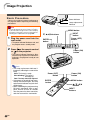
Basic Procedure
Power indicator
Connect the required external equipment to
the projector before operating the following
procedures.
Lamp replacement
indicator
Info
• The language preset at the factory is English.
If you want to change the on-screen display
to another language, reset the language according to the procedure on page 34.
1
Plug the power cord into the
wall outlet.
MENU button
", ',\, | buttons
ENTER
button
INPUT
button
Power (OFF)
button
• The power indicator illuminates red, and
the projector enters standby mode.
2
Press on the remote control
or
on the projector.
Power (ON)
button
• The power indicator illuminates blue.
After the lamp replacement indicator illuminates, the projector is ready to start
operation.
Note
• The lamp replacement indicator illuminates, indicating the status of the
lamp.
Blue: The lamp is ready.
Blue blinking: The lamp is
warming up.
Red: The lamp should be replaced.
• If the power is turned off and immediately switched on again, the lamp
replacement indicator may take time
to illuminate.
• When controlling the projector using
RS-232C commands from a computer, wait for at least 30 seconds
after the power has been turned on,
and then transmit the commands.
-32
Power (OFF)
button
ENTER
button
Power (ON)
button
MENU button
', ", \, |
buttons
INPUT
buttons
"On-screen Display (Example)
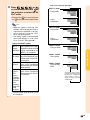
Press
,
,
,
or
on the remote control or on
the projector to select the INPUT mode.
• After pressing
once on the projector,
use to select the desired input mode.
INPUT 1 mode
➝
3
Using RGB*
Using
Component
Note
Using RGB*
Using
Component
INPUT 3 mode
Using S-Video
Basic Operation
➝
INPUT 5 mode
Using Analog
RGB
➝
INPUT 4 mode
Using Video
➝
About the INPUT modes
INPUT 1 Used for projecting images
INPUT 2 from equipment that sends
component signals or RGB
(Component/RGB*) signals connected to the
INPUT 1 or 2 terminals.
INPUT 3 Used for projecting im(S-Video) ages from equipment connected to the S-VIDEO input terminal.
INPUT 4 Used for projecting im(Video)
ages from equipment
connected to the VIDEO
input terminal.
INPUT 5 Used for projecting images from equipment
(Digital PC
connected to the DVI inRGB/
put terminal.
Digital PC
Component/
Digital Video
RGB/Digital
Video
Component/
Analog RGB/
Analog
Component)
INPUT 2 mode
➝
• When no signal is received, “NO
SIGNAL” will be displayed. When a
signal that the projector is not preset to receive is received, “NOT
REG.” will be displayed.
• The INPUT mode is not displayed
when “OSD display” is set to “Level
A” or “Level B”. (See page 64.)
The display varies according to the “Signal Type” with
the INPUT 5. The diagram
shown above is the example of having selected
“Analog RGB”.
* Input the RGB signal of the DTV, not
the computer.
-33
Image Projection
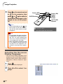
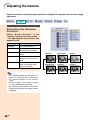
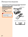
4
Press
or
on the remote control
on the projector, then
or
again while the
press
confirmation message is displayed, to turn off the projector.
Note
• If you accidentally pressed
and
do not want to turn off the power,
wait until the confirmation message
disappears.
Info
• Do not unplug the power cord during projection or cooling fan operation. This can cause damage due
to the rise in internal temperature,
as the cooling fan also stops.
• When connected to equipment such
as an amplifier, be sure to turn off
the power to the equipment connected first and then to the projector.
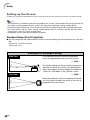
Selecting the On-screen
Display Language
• The on-screen display language of the
projector can be set to English, German,
Spanish, Dutch, French, Italian, Swedish,
Portuguese, Chinese, Korean or Japanese.
1
Press
2
Press \ or | to select “Language”.
-34
.
• The menu will be displayed.
Power (OFF)
button
ENTER button
Power (ON)
button
MENU
button
', ", \, |
buttons
3
Press ' or " to select the desired language, and then press
.
4
Press
.
• The desired language will be set as
the on-screen display.
Basic Operation
-35
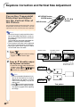
Keystone Correction and Vertical Size Adjustment
Correcting Trapezoidal
Distortion and Adjusting the Vertical Size of
the Picture
KEYSTONE button
ENTER button
', ", \, |
buttons
UNDO button
This function allows for Keystone (On-screen
Trapezoidal Distortion) Correction and the
adjustment of the vertical size of the picture.
Note
• When the image is projected either from
top or from bottom toward the screen at
an angle, the image becomes distorted
trapezoidally.
The function for correcting trapezoidal distortion is called Keystone Correction.
• The Keystone Correction can be adjusted
up to angle of approximately ±20 degrees.
• There are some input signal in which
“KEYSTONE” does not work.
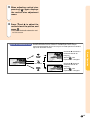
1
Press
.
Normal screen
Keystone Correction screen
* Vertical size
adjustment screen
• Each time
is pressed, the settings
toggles as shown on the right.
2
Press ', ", \ and | to adjust
the Keystone correction.
• If you want to make more detailed corto display the test
rections, press
pattern, and then press ', ", \ and
| to make the adjustments.
* “V-SIZE” is not displayed when the value
of “KEYSTONE” is “0”.
Compresses
upper side.
Note
• Since the trapezoidal distortion of the image can be corrected up to an angle of
approximately ±20 degrees, the actual
screen can be diagonally set up to that
angle as well.
• Press
to cancel Keystone Correction.
• Straight lines or the edges of images
may appear jagged while adjusting
the image.
-36
Compresses
lower side.
Test pattern
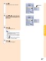
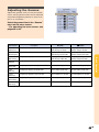
3
When adjusting vertical size,
again displays
pressing
the vertical size adjustment
menu.
4
Press "and ' to adjust the
vertical size of the picture, and
press .
• See below for details about the vertical size screen.
Ajuste de Tamanho Vertical
A razão parente da tela poderá variar quando a função de
deslocamento da lente é usada em combinação com a função
Correção Trapezoidal. Neste caso, ajuste a razão aparente usando o
ajuste de tamanho vertical.
Basic Operation
Premindo ' aumenta o
tamanho vertical da
imagem.
Aperte
para
reposicionar a imagem.
Tecla UNDO
Premindo " diminui o
tamanho vertical da
imagem.
Aperte
para
reposicionar a imagem.
-37
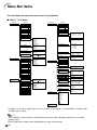
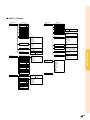
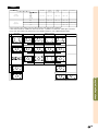
Menu Bar Items
This list shows the items that can be set in the projector.
■ INPUT 1 / 2 / 5 Mode
Main menu
Picture
Page 44
Main menu
Sub menu
Sub menu
Fine Sync
Contrast
–30
+30
Bright
–30
+30
Color
–30
+30
H-Pos
Tint
–30
+30
V-Pos
Sharp
–30
+30
Reset
CLR Temp
5500 11500
Clock
Page 53
–150
–60
Phase
–150
–60
+150
+60
+150
+60
Save Setting
Resolution Vert Freq
1 1024 × 768
60 Hz
2
800 × 600
75 Hz
Select Setting
Reset
•
•
White Emphasis [ON/OFF]
Gamma Position
7
Standard
Black Detail
Brighten
Custom 1
Custom 2
SVM Gamma
Resolution Vert Freq
60 Hz
1 1024 × 768
75 Hz
2 800 × 600
•
•
7
Special Modes
Color Selected
Standard
Custom 1
Custom 2
Custom 3
1
2
3
4
Progressive Mode
2D Progressive
3D Progressive
Film Mode
7
Picture Setting
Memory 1 Memory 5
INPUT1 / 2 / 5 Memory
•
•
Gamma Position
Standard
Black Detail
Brighten
Custom 1
Custom 2
SVM Gamma
Resolution
Hor Freq
Vert Freq
Auto Sync
OFF
Normal
High Speed
R-Gamma
–30
+30
G-Gamma
–30
+30
B-Gamma
–30
+30
R-Gain
–30
+30
G-Gain
–30
+30
B-Gain
–30
+30
Lamp Timer
R-Offset
–30
+30
OSD Display
G-Offset
–30
+30
Normal
Level A
Level B
B-Offset
–30
+30
Signal Type
RGB
Component
Background
Blue
None
Economy Mode
Power Save [ON/OFF]
RS-232C Port [ON/OFF]
Auto Power Off [ON/OFF]
RS-232C
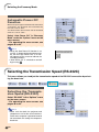
9600 bps
38400 bps
115200 bps
PRJ Mode
Front
Ceiling + Front
Rear
Ceiling + Rear
Options
Page 62
Digi. Shift
–30
+30
Subtitle
–30
+30
Reset
DNR
*
Reset
C.M.S.
1024 × 768
48.4 KHz
60 Hz
Signal Info
Auto Sync Disp [ON/OFF]
Gamma
Page 48
Resolution
1024 × 864
1152 × 864
1152 × 870
1152 × 882
Color Selected
Standard
Custom 1
Target
[R] Red
[Y] Yellow
[G] Green
[C] Cyan
[B] Blue
[M] Magenta
Page 50
Lightness
–30
+30
Chroma
–30
+30
Hue
–30
+30
Custom 3
Reset (This Color)
Reset (All Colors)
Language
View Settings
Page 34
English
Deutsch
Español
Nederlands
Français
Italiano
Svenska
Português
OFF
Level 1
Level 3
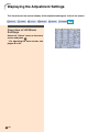
Status
Page 70
*In INPUT 5, the items in “Signal Type” are “D. PC RGB”, “D. PC Comp.”, “D. Video RGB”, “D. Video Comp.”
“A. RGB” and “A. Comp.”.
Note
• The resolution, vertical frequency and horizontal frequency figures displayed above are for example
purposes only.
• Picture adjustment settings differ depending on the type of input signal.
-38
■ INPUT 3 / 4 Mode
Main menu
Picture
Page 44
Sub menu
Main menu
Sub menu
Options
Digi. Shift
–30
+30
Page 62
Subtitle
–30
+30
Contrast
–30
+30
Bright
–30
+30
Color
–30
+30
Reset
DNR
Tint
–30
+30
Sharp
–30
+30
CLR Temp 5500
11500
Normal
Level A
Level B
Gamma Position
Standard
Black Detail
Brighten
Custom 1
Custom 2
SVM Gamma
Video System
Auto
PAL (50/60Hz)
SECAM
NTSC4.43
NTSC3.58
PAL-M
PAL-N
Color Selected
Standard
Custom 1
Custom 2
Custom 3
Background
Blue
None
Progressive Mode
2D Progressive
3D Progressive
Film Mode
Economy Mode
Power Save [ON/OFF]
RS-232C Port [ON/OFF]
Auto Power Off [ON/OFF]
Picture Setting
Memory 1 Memory 5
INPUT3 / 4 Memory
RS-232C
9600 bps
38400 bps
115200 bps
R-Gamma
–30
+30
G-Gamma
–30
+30
B-Gamma
–30
+30
R-Gain
–30
+30
G-Gain
–30
+30
B-Gain
–30
+30
R-Offset
–30
+30
G-Offset
–30
+30
B-Offset
–30
+30
Standard
Black Detail
Brighten
Custom 1
Custom 2
SVM Gamma
PRJ Mode
Front
Ceiling + Front
Rear
Ceiling + Rear
Language
Page 34
Basic Operation
OSD Display
White Emphasis [ON/OFF]
Gamma Position
Level 3
Lamp Timer
Reset
Gamma
Page 48
OFF
Level 1
English
Deutsch
Español
Nederlands
Français
Italiano
Svenska
Português
Reset
Status
Page 70
C.M.S.
Page 50
Color Selected
Standard
Custom 1
Target
[R] Red
[Y] Yellow
[G] Green
[C] Cyan
[B] Blue
[M] Magenta
Lightness
–30
+30
Chroma
–30
+30
Hue
–30
+30
Custom 3
Reset (This Color)
Reset (All Colors)
View Settings
-39
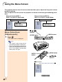
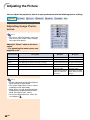
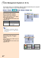
Using the Menu Screen
This projector has two sets of menu screens that allow you to adjust the image and various
projector settings.
You can operate the menus from the projector or remote control using the following procedure.
Menu screen for INPUT 1,
INPUT 2 or INPUT 5 RGB mode
Menu screen for INPUT 3,
INPUT 4 or INPUT 5 VIDEO Mode
Menu Bar
(Main Menu)
Menu Selections
(Adjustments)
1
Press
Menu Bar
(Main Menu)
", ', \, |
buttons
ENTER button
MENU button
.
• The menu screen is displayed.
Note
• The “Picture” menu screen for the
selected input mode is displayed.
• The on-screen display shown on the
lower right is displayed when the INPUT 1, 2 or 5 mode is selected while
RGB signals are input.
ENTER
button
MENU button
', ", \, |
buttons
"Menu Screen
-40
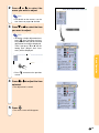
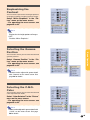
2
Press \ or | to select the
menu you want to adjust.
Note
• For details on the menus, see the
tree charts on pages 38 and 39.
3
Press " or ' to select the item
you want to adjust.
Note
• To display a single adjustment item,
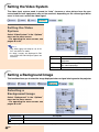
press
after selecting the item.
Only the menu bar and the selected
adjustment item will be displayed.
Then if you press " or ', the following item (“Bright” after “Contrast”) will be displayed.
• Press
Basic Operation
|
to return to the previous
screen.
4
Press \ or | to adjust the item
selected.
• The adjustment is stored.
5
Press
.
• The menu screen will disappear.
-41
Using the Menu Screen
Menu Selections
(Settings)
1
Press
" , ', \, |
buttons
ENTER button
MENU button
.
• The menu screen is displayed.
Note
• The “Picture” menu screen for the
selected input mode is displayed.
• The on-screen displays shown on
the lower right are displayed when
INPUT 1, 2 or 5 mode is selected
while RGB signals are input.
2
Press \ or | to select the
menu you want to adjust.
ENTER
button
MENU button
', " , \, |
buttons
Note
• For details on the menus, see the
tree charts on pages 38 and 39.
3
▼ Menu screen
Press " or ' to select the
item you want to set.
Note
• Press
to return to the previous
screen.
• In some menus, select the icon us”.
ing “
Sub menu
-42
4
Press |.
• The cursor shifts to the sub menu.
Press " or ' to select the setting of the item displayed in the
sub menu.
6
Press
Basic Operation
5
Sub menu
.
• The item selected is set.
Note
• Some adjustment items will display
a confirmation message.
When setting an item, press \ or
| to select “Yes” or “OK” and then
press
.
to select “ON” or “OFF” for
• Use
the item of “Economy Mode”.
7
Press
.
• The menu will disappear.
-43
Adjusting the Picture
You can adjust the projector’s picture to your preferences with the following picture settings.
Adjusting Image Preferences
Note
• First select “INPUT # Memory” when you
want to save the “Picture” menu settings.
See page 47 for details.
Adjust the “Picture” menu on the menu
screen.
➝For operating the menu screen, see
pages 40 to 43.
Selected Item
Description
\ button
| button
Contrast
For adjusting the contrast level
For less contrast
For more contrast
Bright
For adjusting the brightness of an image
For less brightness
For more brightness
Color
For adjusting the color intensity of an image
For less color intensity For more color intensity
Tint
For adjusting the tones of an image
Skin tones become purplish
Skin tones become greenish
Sharp
For making sharper or softer the contour of an image For less sharpness
Decreases color
For adjusting the color temperature of an image
temperature for warmer,
reddish, incandescentlike images.
For more sharpness
Increases color
temperature for cooler,
bluish, fluorescent-like
images.
CLR Temp
Note
• Picture adjustment settings differ depending on the type of input signal.
• The picture adjustments can be stored
separately in each input mode.
• Some items may not be adjustable depending on the combination of the INPUT
mode and “Signal Type” setting.
• To reset all adjustment items, select “Reset” and press .
-44
Emphasizing the
Contrast
This function emphasizes the bright portions
of images to obtain a higher contrast image.
Select “White Emphasis” in the “Picture” menu on the menu screen.
➝For operating the menu screen, see
pages 40 to 43.
Note
• ON
Emphasizes the bright portions of images.
• OFF
Disables “White Emphasis”.
Basic Operation
Selecting the Gamma
Position
This function allows you to select the desired
gamma position.
Select “Gamma Position” in the “Picture” menu on the menu screen.
➝For operating the menu screen, see
pages 40 to 43.
Note
• Gamma can be adjusted in greater detail
with “Gamma” on the menu screen. See
page 48 for details.
Selecting the C.M.S.
Color
This function allows you to select the desired
color reproduction mode.
Select “Color Selected” in the “Picture”
menu on the menu screen.
➝For operating the menu screen, see
pages 40 to 43.
Note
• Color can be adjusted in greater detail with
“C.M.S.” on the menu screen. See page
50 for details.
-45
Adjusting the Picture
Progressive Mode
This function allows you to select the progressive display of a video signal. The progressive display projects a smoother video
image.
Select “Progressive Mode” in the “Picture” menu on the menu screen.
➝For operating the menu screen, see
pages 40 to 43.
Note
•
2D Progressive
This function is useful to display fastmoving images such as sports and action films. This mode optimizes the image in a displayed frame.
3D Progressive
•
This function is useful to display relatively
slow-moving images such as drama and
documentary more clearly.
This mode optimizes the image by estimating the movement of a number of preceding and succeeding frames.
Film Mode
•
Reproduces the image of film source
clearly. Displays the optimized image of
film transformed with three-two pull down
(NTSC and PAL60Hz) or two-two pull
down (PAL50Hz and SECAM) enhancement to progressive mode images.
* The film source is a digital video recording with the original encoded as is at 24
frames/second. The projector can convert this film source to progressive video
at 60 frames/second with NTSC and
PAL60Hz or at 50 frames/second with
PAL50Hz and SECAM to play back a
high-definition image.
• When using progressive inputs, these
inputs are directly displayed so that 2D
Progressive, 3D Progressive and Film
Mode cannot be selected. These modes
can be selected in interlace signals other
than 1080I.
• In NTSC or PAL60Hz, even if the 3D Progressive mode has been set, the threetwo pull down enhancement will be enabled automatically, when the film source
has been entered.
• In PAL50Hz or SECAM, the two-two pull
down enhancement will be enabled only
in the Film Mode, when the film source
has been entered.
-46
Picture Setting Function
This function stores all items set in “Picture”.
Five settings can be stored separately in
“Memory 1” to “Memory 5”. Each stored setting is reassigned to each input mode (INPUT
1 to INPUT 5). Even when the input mode or
signal is changed, you can easily select optimal settings from the stored settings.
■ When Saving:
Select “Memory #” or “INPUT # Memory”
before setting on the “Picture” menu.
Select “Picture Setting” in the “Picture”
menu on the menu screen.
➝For operating the menu screen, see
pages 40 to 43.
Selected item
Basic Operation
Description
Settings of all items in “PicMemory 1
ture” can be stored for the reto
spective input modes. The
Memory 5
stored settings can be selected in any input modes.
Besides “Memory 1” to
“Memory 5”, other settings
INPUT 1 Memory
can be stored for each input
to
mode. “INPUT 1-5 Memory”
INPUT 5 Memory
can be selected for each input mode.
■ When Recalling Saved Settings:
When a saved memory number is selected,
the “Picture” menu settings change accordingly.
Note
• The items of “Picture Setting” can be selected directly by pressing
. The items
change in the order of “Memory 1” –
“Memory 5” and then “INPUT #
is pressed.
Memory” each time
■ When Changing Saved Settings:
When changing the saved “Picture” menu
settings, select the memory number first.
PICTURE SETTING button
-47
Adjusting the Gamma
Use this function to select the gamma position and adjust the gamma curve for finer image
adjustment.
Selecting the Gamma
Position
Select “Gamma Position” in the
“Gamma” menu on the menu screen.
➝For operating the menu screen, see
pages 40 to 43.
Selected item
Standard
Black Detail
Brighten
Custom 1–2
SVM Gamma
Description
For Standard picture.
Gives greater depth to
darker portions of image.
Brightens darker portions of
image.
Allows you to adjust the
gamma curve for each of
RGB.
Allows you to adjust gamma
value using SharpVision
Manager Software.
Note
• The gamma position you make the setting in this menu for can be selected in
the “Gamma Position” in the “Picture”
menu.
• Select “Custom 1” or “Custom 2” to make
the more detailed gamma setting.
• For selecting “SVM Gamma”, refer to the
SharpVison Manager operation manual
(supplied).
-48
Standard
Black Detail
Brighten
SVM Gamma
Custom 2
Custom 1
Adjusting the Gamma
Adjust the gamma curve to suit your preferences. These gamma values can be adjusted
only when the gamma position is set to “Custom 1” or “Custom 2”.
Select the gamma item in the “Gamma”
menu on the menu screen.
➝For operating the menu screen, see
pages 40 to 43.
Selected Item
Description
\ button
| button
For adjusting the display characteristic of red color
For giving greater depth to brighter For giving greater depth to darker
portion of image in red color.
portion of image in red color.
G-Gamma
(Green Gamma)
For adjusting the display characteristic of green color
For giving greater depth to brighter For giving greater depth to darker
portion of image in green color.
portion of image in green color.
B-Gamma
(Blue Gamma)
For adjusting the display characteristic of blue color
For giving greater depth to brighter For giving greater depth to darker
portion of image in blue color.
portion of image in blue color.
R-Gain
(Red Gain)
For adjusting the contrast level of red color
For less contrast in red color
For more contrast in red color
G-Gain
(Green Gain)
For adjusting the contrast level of green color
For less contrast in green color
For more contrast in green color
B-Gain
(Blue Gain)
For adjusting the contrast level of blue color
For less contrast in blue color
For more contrast in blue color
R-Offset
(Red Offset)
For adjusting the brightness level of red color
For less brightness in red color
For more brightness in red color
G-Offset
(Green Offset)
For adjusting the brightness level of green color
For less brightness in green color
For more brightness in green color
B-Offset
(Blue Offset)
For adjusting the brightness level of blue color
For less brightness in blue color
For more brightness in blue color
Basic Operation
R-Gamma
(Red Gamma)
-49
Color Management System (C. M. S.)
This function allows you to individually adjust the display characteristics of six colors (R:
Red, Y: Yellow, G: Green, C: Cyan, B: Blue, M: Magenta) .
Selecting the Color
Reproduction Mode
Select “Color Selected” in the “C.M.S.”
menu on the menu screen.
➝For operating the menu screen, see
pages 40 to 43.
Selected item
Standard
Custom 1-3
Description
Sharp default setting
“Lightness”, “Chroma” and
“Hue” can be adjusted for each
of the six colors.
Note
• If “Standard” is selected for “Color Selected”, other items (e.g., Target) cannot
be adjusted.
Selecting the Target
Color
Select “Target” in the “C.M.S.” menu on
the menu screen.
➝For operating the menu screen, see
pages 40 to 43.
-50
Red
Cyan
Yellow
Blue
Green
Magenta
Setting the Brightness
of the Target Color
Select “Lightness” in the “C.M.S.”
menu on the menu screen.
➝For operating the menu screen, see
pages 40 to 43.
Setting the Chromatic
Value of the Target
Color
Basic Operation
Select “Chroma” in the “C.M.S.” menu
on the menu screen.
➝For operating the menu screen, see
pages 40 to 43.
Setting the Hue of the
Target Color
Select “Hue” in the “C.M.S.” menu on
the menu screen.
➝For operating the menu screen, see
pages 40 to 43.
-51
Color Management System (C.M.S.)
Resetting User-Defined
Color Settings
Select “Reset (This Color)” or “Reset
(All Colors)” in the “C.M.S.” menu on
the menu screen.
➝For operating the menu screen, see
pages 40 to 43.
Selected item
Reset
(This Color)
Reset
(All Colors)
Description
“Lightness”, “Chroma” and “Hue”
of the color selected for “Target”
are reset.
“Lightness”, “Chroma” and
“Hue” of all colors are reset.
Overview of All Color
Settings
Select “View Settings” in the “C.M.S.”
menu on the menu screen.
➝For operating the menu screen, see
pages 40 to 43.
-52
Adjusting Computer Images
Use the Fine Sync function in case of irregularities such as vertical stripes or flickering in
portions of the screen.
When Auto Sync is OFF
When “Auto Sync” is “OFF”, interference
such as flickering or vertical stripes may occur if displaying tilings or vertical stripes.
Should this occur, adjust “Clock”, “Phase”,
“H-Pos” and “V-Pos” for obtaining an optimum image.
Selected Item
Basic Operation
Select “Clock”, “Phase”, “H-Pos” or “VPos” in the “Fine Sync” menu on the
menu screen.
➝For operating the menu screen, see
pages 40 to 43.
Description
Clock
Adjusts vertical noise.
Phase
Adjusts horizontal noise (similar to tracking on your VCR).
H-Pos
Centers the on-screen image by moving it to the left or right.
V-Pos
Centers the on-screen image by moving it up or down.
Note
• Computer image adjustments can be made
. See page 55 for
easily by pressing
details.
Saving Adjustment
Settings
This projector allows you to store up to seven
adjustment settings for use with various computers.
Select “Save Setting” in the “Fine Sync”
menu on the menu screen.
➝For operating the menu screen, see
pages 40 to 43.
-53
Adjusting Computer Images
Selecting Adjustment Settings
Adjustment settings stored in the projector
can be easily accessed.
Select “Select Setting” in the “Fine
Sync” menu on the menu screen.
➝For operating the menu screen, see
pages 40 to 43.
Note
• If a memory position has not been set, a
resolution and frequency setting will not
be displayed.
• When selecting a stored adjustment setting with “Select Setting”, you can set the
projector in the stored adjustments.
Special Mode Settings
Ordinarily, the type of input signal is detected
and the correct resolution mode is automatically selected. However, for some signals, the
optimal resolution mode in “Special Modes” on
the “Fine Sync” menu screen may need to be
selected to match the computer display mode.
Set the resolution by selecting “Special
Modes” in the “Fine Sync” menu on the
menu screen.
➝For operating the menu screen, see
pages 40 to 43.
Note
• Avoid displaying computer patterns which
repeat every other line (horizontal stripes).
(Flickering may occur, making the image
hard to see.)
• When a DVD player or Digital Video is connected, select 480P as the input signal.
• See “Checking the Input Signal” on the next
page for information on the currently selected
input signal.
-54
Checking the Input Signal
This function allows you to check the current
input signal information.
Select “Signal Info” in the “Fine Sync”
menu on the menu screen.
➝For operating the menu screen, see
pages 40 to 43.
Auto Sync Adjustment
Used to automatically adjust a computer image.
Select “Auto Sync” in the “Fine Sync”
menu on the menu screen.
➝For operating the menu screen, see
pages 40 to 43.
Note
Manual adjustments should be performed:
• When the optimum image cannot be
achieved with Auto Sync adjustment. See
page 53.
• Auto Sync adjustment may take some
time to complete, depending on the image of the computer connected to the projector.
• When setting “Auto Sync” to “OFF” or
is pressed Auto
“High Speed”, and if
Sync will be executed in “High Speed”
mode. If the button is pressed again
within one minute, Auto Sync will be executed in “Normal” mode.
Basic Operation
When setting to “ Normal” or
“
High Speed”:
• Auto Sync adjustment will occur when the
projector is turned on or when the inputs
are switched, when connected to a computer.
Screen display during Auto Sync
AUTO SYNC button
-55
Adjusting Computer Images
Auto Sync Display
Function
Used to set the screen displayed during Auto
Sync.
Select “Auto Sync Disp” in the “Fine
Sync” menu on the menu screen.
➝For operating the menu screen, see
pages 40 to 43.
Selected item
-56
Description
The image set as a background image is projected.
The computer image being
adjusted is displayed.
Easy to Use Functions
Easy to Use Functions
Selecting the Picture Display Mode
This function allows you to modify or customize the picture display mode to enhance the
input image. Depending on the input signal, you can choose “SIDE BAR”, “SMART STRETCH”,
“CINEMA ZOOM”, “STRETCH”, “NORMAL” or “DOT BY DOT” image.
Switching the Picture
Display Using Different
Input Signals
Press
RESIZE button
.
• Each time
is pressed, the display
changes as shown on pages 59 and 60.
Info
• In the Dot by Dot Mode, images are displayed in the original resolution, therefore
they will not be enlarged.
• To return to the standard image, press
while “RESIZE” is displayed on the screen.
RESIZE
button
Screen display of the picture display mode
-58
VIDEO
For 4:3
aspect ratio
For 16:9
aspect ratio
SIDE BAR
SMART
STRETCH
CINEMA
ZOOM
STRETCH
DOT BY DOT
480I
480P
576I
576P
NTSC
PAL
SECAM
960 ⳯ 720
1280 ⳯ 720
1280 ⳯ 720
1280 ⳯ 720
–
480P
960 ⳯ 720
1280 ⳯ 720
1280 ⳯ 720
1280 ⳯ 720
–
720P
–
–
–
1280 ⳯ 720
1280 ⳯ 720
1080I
–
–
–
1280 ⳯ 720
–
• Select “DOT BY DOT” during 720P input when viewing 720P output from a computer.
• 720P switches between “STRETCH” and “DOT BY DOT”. “STRETCH” is fixed when 1080I signal is entered.
• “Digi. Shift” and “Subtitle” only move when in the “SMART STRETCH” and “CINEMA ZOOM” modes.
Input Signal
SIDE BAR
Output screen image
CINEMA ZOOM
SMART STRETCH
*
*
*
*
*
*
STRETCH
DOT BY DOT
4:3 aspect ratio
480I
480P
540P
576I
576P
NTSC
PAL
SECAM
Letterbox
Squeeze
540P
1080I
16:9 aspect ratio
720P
Easy to Use Functions
-59
Selecting the Picture Display Mode
COMPUTER
SVGA (800 ⳯ 600)
For 4:3
aspect ratio
For without
4:3 aspect ratio
NORMAL
DOT BY DOT
960 ⳯ 720
800 ⳯ 600
XGA (1024 ⳯ 768)
960 ⳯ 720
1024 ⳯ 720
SXGA (1280 ⳯ 960)
960 ⳯ 720
1280 ⳯ 720
SXGA (1280 ⳯ 1024)
900 ⳯ 720
1280 ⳯ 720
• “NORMAL” is fixed when XGA (1024 × 768) signals are entered.
Input Signal
VGA
4:3 aspect ratio
(640 ⳯ 480)
SVGA
4:3 aspect ratio
(800 ⳯ 600)
XGA
4:3 aspect ratio
(1024 ⳯ 768)
SXGA
5:4 aspect ratio
(1280 ⳯ 1024)
-60
Output screen image
NORMAL
DOT BY DOT
Switchable High Contrast/High Brightness Mode
This function controls the quantity of the projected light and the contrast of the image. It can
be operated using the HIGH CONTRAST/HIGH BRIGHTNESS MODE button on the projector.
Set “HIGH BRIGHTNESS MODE” when the projector is used in a relatively bright room.
Operating the Theater
Mode Function
Press the HIGH CONTRAST/HIGH
BRIGHTNESS MODE button to select the “HIGH CONTRAST MODE”
or “HIGH BRIGHTNESS MODE”.
Selected mode
Description
HIGH CONTRAST
MODE
This mode is
recommended for dark
environments.
HIGH BRIGHTNESS
MODE
This mode is
recommended for
bright environments.
HIGH CONTRAST/
HIGH BRIGHTNESS MODE
button
Note
• The projector is set to the “HIGH CONTRAST MODE” when shipped from the
factory.
Easy to Use Functions
-61
Digital Shift Function
For easier viewing, this function shifts the entire image projected on the screen up or down
when projecting 16:9 images from DVD players and DTV* decoders.
* DTV is the umbrella term used to describe the new digital television system in the United
States.
Adjusting the Digital
Shift
Select “Digi. Shift” in the “Options”
menu on the menu screen.
➝For operating the menu screen, see
pages 40 to 43.
Note
• The Digital Shift Function works with the
SMART STRETCH and CINEMA ZOOM
screen. For details, see pages 59 and 60.
Subtitle Setting
With this function, you can adjust the vertical size of the display to allow for subtitles.
Adjusting the Vertical
Size of the Display
Select “Subtitle” in the “Options” menu
on the menu screen.
➝For operating the menu screen, see
pages 40 to 43.
Note
• When changing the screen with the Subtitle setting, not only the bottom of the
screen rises, but also the upper part is
changed to a certain point.
• The subtitle setting can be adjusted more
effectively with the Digital Shift function.
• The subtitle setting can be made only with
the SMART STRETCH and CINEMA
ZOOM screen. For details, see pages 59
and 60.
-62
Video Digital Noise Reduction (DNR) System
Digital Noise Reduction (DNR) provides high quality images with minimal dot crawl and cross
color noise.
Reducing Image Noise
Select “DNR” in the “Options” menu on
the menu screen.
➝For operating the menu screen, see
pages 40 to 43.
Note
• Set a level so as to view a clearer picture.
Make sure to set DNR to “OFF” in the following cases:
• When the image is blurry.
• When the contours and colors of moving
images drag.
• When TV broadcasts with weak signals
are projected.
Note
• This function is available with INPUT 1, 2
(480I, 480P, 580I and 580P signals) and
INPUT 3, 4 (all signals).
Easy to Use Functions
Displaying the Lamp Usage Time
Confirming the Lamp
Usage Time
This function allows you to check the lamp
usage time.
Select “Options” menu to see the lamp
usage time.
Lamp Usage Time
Note
• It is recommended that the lamp be
changed after approximately 1,900 cumulative hours of use.
-63
Setting On-screen Display
This function allows you to turn on or off the on-screen messages. When setting “
Level A”
or “
Level B” in “OSD Display”, the input mode display (e.g. INPUT 1) will not appear, even
if the INPUT button is pressed.
Turning Off the
On-screen Display
Select “OSD Display” in the “Options”
menu on the menu screen.
➝For operating the menu screen, see
pages 40 to 43.
Selected Item
-64
Description
Normal
All On-screen Displays are displayed.
Level A
Input and Auto Sync are not displayed.
Level B
All On-screen Displays are not displayed.
(except for Menu, On-screen Displays displayed when the KEYSTONE button is pressed,
and warning displays (Power off/Temp./Change The Lamp., etc.))
Selecting the Signal Type
This function allows you to select the input signal type RGB or Component for INPUT 1 and
2, or Digital PC RGB, Digital PC Component, Digital Video RGB, Digital Video Component,
Analog RGB or Analog Component for INPUT 5.
Selecting the Signal
Type
For INPUT 1 and INPUT 2
Select “Signal Type” in the “Options”
menu on the menu screen.
➝For operating the menu screen, see
pages 40 to 43.
Note
For INPUT 1 and INPUT 2
Set when RGB signals are
received from video equipment.
Set when analog component
Component signals are received from
video equipment.
RGB
For INPUT 5
For INPUT 5
Set when digital PC RGB
signals are received from
the computer.
Set when digital PC component signals are reD. PC Comp.
ceived from the computer.
Set when digital video
RGB signals are reD. Video RGB
ceived from video equipment.
Set when digital video
component signals are
D. Video Comp.
received from video
equipment.
Set when analog RGB
A. RGB
signals are received.
Set when analog compoA. Comp.
nent signals are received.
• The input signal type can also be switched
by pressing
. This switching at this time
is only able to be performed for switching
the of the above table.
Easy to Use Functions
D. PC RGB
RGB/COMP. button
-65
Setting the Video System
The video input system mode is preset to “Auto”; however, a clear picture from the connected audio-visual equipment may not be received, depending on the video signal difference. In that case, switch the video signal.
Setting the Video
System
Select “Video System” in the “Options”
menu on the menu screen.
➝For operating the menu screen, see
pages 40 to 43.
Note
• The video signal can only be set in INPUT 3 or INPUT 4 mode.
• In “Auto”, images are displayed in PAL
even if PAL-N or PAL-M input signals are
received.
PAL
SECAM
NTSC4.43
NTSC3.58
When connected to PAL video equipment.
When connected to SECAM video
equipment.
When reproducing NTSC signals in
PAL video equipment.
When connected to NTSC video equipment.
Setting a Background Image
This function allows you to select the image displayed when no signal is being sent to the projector.
Selecting a
Background Image
Select “Background” in the “Options”
menu on the menu screen.
➝For operating the menu screen, see
pages 40 to 43.
Selected Item
Description
Blue
Blue screen
None
Black screen *
* If the input signal has interference, the screen will be displayed with the interference.
-66
Selecting the Economy Mode
These functions allow you to reduce the power consumption of the projector.
Setting the Power Save
Select “Power Save” in “Economy
Mode” under the “Options” menu on the
menu screen.
➝For operating the menu screen, see
pages 40 to 43.
Note
• Although noise is reduced when “Power
Save” is set to “ON”, brightness decreases
by 20%.
• “Power Save” mode is factory preset to
“OFF”.
• “Power Save” is switched on and off by
pressing .
Brightness
Power
consumption
ON
(Low power
mode)
80%
220 W
OFF
(Standard mode)
100%
270 W
Status
RS-232C Off Function
Easy to Use Functions
This projector consumes power when using a
computer connected to the RS-232C terminal.
When not using these terminals, “RS-232C
Port” can be set to “OFF” to reduce standby
power consumption.
Select “RS-232C Port” in “Economy
Mode” under the “Options” menu on the
menu screen.
➝For operating the menu screen, see
pages 40 to 43.
ON
RS-232C connection is set to “ON”.
The RS-232C is operating at all
times (to accept communications).
OFF
RS-232C connection is set to
“OFF”. RS-232C does not operate
when the power supply is in
standby.
Note
• Set “RS-232C Port” to “ON” when using the
SharpVision Manager Software.
• “RS-232C Port” is switched on and off by
.
pressing
-67
Selecting the Economy Mode
Automatic Power Off
Function
When no input signal is detected for more than
15 minutes, the projector will automatically
turn off if set to “ON”.
The Auto Power Off function will be disabled
when it is set to “OFF”.
Select “Auto Power Off” in “Economy
Mode” under the “Options” menu on the
menu screen.
➝For operating the menu screen, see
pages 40 to 43.
Note
• When the Auto Power Off function is set
to “ON”, 5 minutes before the power turns
off, the message “Power OFF in X min.”
will appear on the screen to indicate the
remaining minutes.
• “Auto Power Off” is switched on and off
.
by pressing
Selecting the Transmission Speed (RS-232C)
This menu allows you to adjust the transmission speed of the RS-232C connection by selecting the baud rate.
Selecting the Transmission Speed (RS-232C)
Select “RS-232C” in the “Options” menu
on the menu screen.
➝For operating the menu screen, see
pages 40 to 43.
Note
• Make sure that both the projector and
computer are set for the same baud rate.
Refer to the computer’s operation manual
for instructions for setting the computer’s
baud rate.
-68
Reversing/Inverting Projected Images
This projector is equipped with a reverse/invert image function that allows you to reverse or
invert the projected image for various applications.
Setting the Projection
Mode
Select “PRJ Mode” in the “Options”
menu on the menu screen.
➝For operating the menu screen, see
pages 40 to 43.
Selected Item
Description
Front
Normal image
Ceiling + Front
Inverted image
Rear
Reversed image
Ceiling + Rear
Reversed and inverted image
Front
Ceiling+Front
Rear
Ceiling+Rear
Easy to Use Functions
Note
• This function is used for the reversed image and ceiling-mount setups. See page
30 for these setups.
-69
Displaying the Adjustment Settings
This function can be used to display all the adjusted settings as a list on the screen.
Overview of All Menu
Settings
Select the “Status” menu on the menu
screen and press
.
➝For operating the menu screen, see
pages 40 to 43.
-70
Appendix
Appendix
Maintenance
Cleaning the projector
Cleaning the lens
■ Be sure to unplug the power cord before cleaning the projector.
■ The cabinet as well as the operation panel is
made of plastic. Avoid using benzene or thinner,
as these can damage the finish on the cabinet.
■ Do not use volatile agents such as insecticides
on the projector.
Do not attach rubber or plastic items on the projector for long time.
The effects of some of the agents in the plastic
may cause damage to the quality or finish of the
projector.
■ Use a commercially available blower or lens
cleaning paper (for glasses and camera lenses)
for cleaning the lens. Do not use any liquid type
cleaning agents, as they may wear off the coating film on the surface of the lens.
■ As the surface of the lens can easily get damaged, be sure not to scrape or hit the lens.
Cleanin
Paper g
Wax
Thinner
■ Wipe off dirt gently with a soft flannel cloth.
ent
terg
l de
utra
Ne
Neutral detergent
diluted with water
■ When the dirt is hard to remove, soak a cloth in a
neutral detergent diluted with water, wring the
cloth well and then wipe the projector.
Strong cleaning detergents may discolor, warp
or damage the coating on the projector.
Make sure to test on a small, inconspicuous area
on the projector before using.
-72
Cleaning the exhaust and intake vents
■ Use a vacuum cleaner to clean dust from the
exhaust vent and the intake vent.
Cleaning the Ventilative Holes
• This projector is equipped with
ventilative holes to ensure the optimal operating condition of the projector.
• Periodically clean the ventilative hole
by vacuuming it off with a vacuum
cleaner.
• The ventilative holes should be
cleaned every 100 hours of use. Clean
the ventilative holes more often when
the projector is used in a dirty or
smoky location.
Cleaning the
Ventilative Holes
1
Side and Rear view
Bottom view
Ventilative
holes
Ventilative
holes
Power
(OFF)
button
Power
(OFF)
button
Press on the projector or
on the remote control to turn
off the power.
• Wait until the cooling fan stops.
Disconnect the Power Cord.
3
Clean the dust off by putting
the cleaner hose on the intake
ventilative holes.
Cleaner
hose
Appendix
2
Cleaner
hose
-73
Maintenance Indicators
■ The warning lights on the projector indicate problems inside the projector.
■ If a problem occurs, either the temperature warning indicator or the lamp replacement indicator will
illuminate red, and the power will turn off. After the power has been turned off, follow the procedures given below.
Power indicator
Lamp replacement indicator
Temperature warning indicator
About the temperature warning indicator
About the lamp replacement indicator
If the temperature inside the projector increases, due to blockage
of the air vents, or the setting lo” will blink in the
cation, “
lower left corner of the picture. If
the temperature keeps on rising,
the lamp will turn off and the temperature warning indicator will
blink, the cooling fan will run for
further 90 seconds, then the power
” apwill be shut off. After “
pears, be sure to perform the following measures.
■ When the lamp exceeds 1,900 cumulative hours of use,
“ ” will be displayed on the screen in
yellow. When the cumulative hours of use
reach 2,000, “ ” will change to red, the
lamp will automatically turn off and then
the projector as well. At this time, the
LAMP REPLACEMENT indicator will illuminate in red.
■ If you try to turn on the projector a fourth
time without replacing the lamp, the projector will not turn on.
Maintenance indicator
Abnormal
Normal
Temperature
warning
indicator
Lamp
replacement
indicator
Power
indicator
-74
Condition
Problem
Possible Solution
Off
Red on/
Power off
• Relocate the projector to an area
• Blocked air intake
with proper ventilation.
The internal
•
Cooling
fan
break•
Take
the projector to your nearest
temperature is
down
Authorized SharpVision Service
abnormally high.
• Internal circuit failure Center or Dealer for repair.
• Clogged air intake
• Clean the ventilative holes according to the procedure on page 73.
Blue on
Blue
blinks
when the
lamp is
active.
Red on/
Power off
The lamp does
not illuminate.
• Burnt-out lamp
• Lamp circuit failure
Red
blinks
Lamp replacement time.
• The lamp usage
time has exceeded
1,900 hours.
Red blinks
The power
indicator blinks
in red when the
projector is on.
Blue on/
Red on
• The exhaust vent
cover is open.
• Carefully replace the lamp. (See
page 77)
• Take the projector to your nearest
Authorized SharpVision Service
Center or Dealer for repair.
• Please exercise care when
replacing the lamp.
• Securely install the cover.
• If the power indicator blinks even
when the exhaust vent cover is
securely installed, contact your
nearest Authorized SharpVision
Service Center or Dealer for
advice.
Info
• If the temperature warning indicator illuminates, and the power turns off, follow the above possible solutions
and then wait until the projector has cooled down completely before plugging in the power cord and turning
the power back on. (At least 5 minutes.)
• If the power is turned off and then turned on again, as during a brief test, the lamp replacement indicator may
be triggered, preventing the power from going on. Should this occur, take the power cord out of the wall outlet
and plug it back in again.
. Make sure the power
• If you want to clean the air vents during projector operation, be sure to first press
has turned off and the cooling fan has stopped, then clean the vents.
• Do not unplug the power cord after the power has been turned off and while the cooling fan is running. The
cooling fan runs for about 90 seconds.
Appendix
-75
Regarding the Lamp
Lamp
■ It is recommended that the lamp (sold separately) be replaced after approximately 1,900 cumulative
hours of use or when you notice a significant deterioration in the picture and color quality. The lamp
usage time can be checked with “Lamp Timer” in the “Options” menu on the menu screen.
■ For lamp replacement, please consult your nearest Authorized SharpVision Service Center or Dealer.
■ The actual lamp service life may be less than 2,000 hours depending on the environment in which
the projector is used.
IMPORTANT NOTE TO U.S. CUSTOMERS:
The lamp included with this projector is backed by a 90-day parts and labor limited warranty. All service
of this projector under warranty, including lamp replacement, must be obtained through an Authorized
SharpVision Service Center or Dealer. For the name of the nearest Authorized SharpVision Service
U.S.A. ONLY
Center or Dealer, please call toll-free: 1-877-DTV-SHARP (1-877-388-7427).
Caution Concerning the Lamp
■ This projector utilizes a pressurized mercury lamp. A loud sound may indicate lamp failure. Lamp
failure can be attributed to numerous sources such as: excessive shock, improper cooling, surface
scratches or deterioration of the lamp due to a lapse of usage time. The period of time up to failure
largely varies depending on the individual lamp and/or the condition and the frequency of use. It is
important to note that failure can often result in the bulb cracking.
■ When the lamp replacement indicator and on-screen display icon are illuminated or flash, it is recommended that the lamp be replaced with a new one immediately, even if the lamp appears to be
operating normally.
■ Should the lamp break, the glass particles may spread inside the lamp cage or gas contained in the
lamp may be vented into the room from the exhaust vent. Because the gas in this lamp includes
mercury, ventilate the room well if the lamp breaks and avoid all exposure to the released gas. In
case of exposure to the gas, consult with a doctor as soon as possible.
■ Should the lamp break, there is also a possibility that glass particles may spread inside of the
projector. In such a case, it is recommended you contact your nearest Authorized SharpVision
Service Center or Dealer to remove the damaged lamp and assure safe operation.
Replacing the Lamp
Caution
• Do not remove the lamp unit immediately after operation of the projector. The lamp will be hot and touching
it can lead to burn or injury.
• Wait at least one hour after the power cord is disconnected to allow the surface of the lamp unit to fully cool
before removing the lamp unit.
■ If the new lamp does not light after replacement, take your projector to the nearest Authorized
SharpVision Service Center or Dealer for repair. Purchase a replacement lamp unit of type BQCXVZ100001 from your nearest Authorized SharpVision Service Center or Dealer. Then carefully change
the lamp by following the instructions described in this section. If you wish, you may have the lamp
replaced at your nearest Authorized SharpVision Service Center or Dealer.
-76
Removing and Installing the Lamp Unit
Info
• Be sure to remove the lamp unit by the
handle. Be sure not to touch the glass
surface of the lamp unit or the inside of
the projector.
• To avoid injury to yourself and damage
to the lamp, be sure to carefully follow
the steps below.
• Do not loosen other screws except for the
lamp unit cover and lamp unit.
(Only the silver screws are loosened).
• Please refer to the installation manual
included with the lamp unit.
1
Lamp
unit
BQC-XVZ100001
Press on the projector or
on the remote control to turn
off the power.
• Wait until the cooling fan stops.
Warning!
• Do not remove the lamp unit from the
projector right after use. The lamp will
be very hot and may cause burn or
injury.
2
Disconnect the power cord.
3
Remove the lamp unit cover.
• Unplug the power cord from the AC
socket.
• Leave the lamp until it has fully cooled
down (about 1 hour).
Appendix
• Loosen the user service screws that
secure the lamp unit cover. Then open
the cover in the direction of the arrow.
User service screws
-77
Regarding the Lamp
4
Remove the lamp unit.
5
Insert the new lamp unit.
6
Attach the lamp unit cover.
• Loosen the securing screws from the
lamp unit. Hold the lamp unit by the
handle and pull it in the direction of
the arrow.
• Press the lamp unit firmly into the lamp
unit compartment. Fasten the securing screws.
• Close the lamp unit cover in the direction of the arrow (to the close mark)
on the side of the projector. Then
tighten the user service screws.
2
Info
• If the lamp unit and lamp cover are not
correctly installed, the power will not turn
on, even if the power cord is connected
to the projector.
Resetting the Lamp Timer
Reset the lamp timer after replacing the lamp.
1
Connect the power cord.
2
Reset the lamp timer.
• Plug the power cord into the AC socket
of the projector.
• While holding down
, " and | on
the projector, press
on the projector.
• “LAMP 0000H” is displayed, indicating that the lamp timer is reset.
Info
• Make sure to reset the lamp timer only
when replacing the lamp. If you reset the
lamp timer and continue to use the same
lamp, this may cause the lamp to become
damaged or explode.
-78
1
User service screws
Connecting Pin Assignments
DVI-I (INPUT 5 / DIGITAL INPUT) port : 29 pin connector
• DVI Digital INPUT
C3
C5
Pin No.
1
2
3
4
5
6
7
8
9
10
11
12
13
14
15
24 23 • • • ~ • • • 18 17
C4
C2
C1
16
8 7• • • • • ~ • • • • • 2 1
••••••••• ~ ••••••••• 9
• DVI Analog RGB Input
Pin No.
1
2
3
4
5
6
7
8
9
10
11
12
13
14
15
Signal
Not connected
Not connected
Not connected
Not connected
Not connected
DDC clock
DDC data
Vertical sync
Not connected
Not connected
Not connected
Not connected
Not connected
+5V power
Ground
Signal
Pin No.
T.M.D.S data 2–
16
T.M.D.S data 2+
17
T.M.D.S data 2 shield 18
Not connected
19
Not connected
20
DDC clock
21
DDC data
22
Not connected
23
T.M.D.S data 1–
24
T.M.D.S data 1+
C1
T.M.D.S data 1 shield C2
Not connected
C3
Not connected
C4
+5V power
C5
Ground
Signal
Hot plug detection
T.M.D.S data 0–
T.M.D.S data 0+
T.M.D.S data 0 shield
Not connected
Not connected
T.M.D.S clock shield
T.M.D.S clock+
T.M.D.S clock–
Not connected
Not connected
Not connected
Not connected
Ground
• DVI Analog Component Input
Pin No.
16
17
18
19
20
21
22
23
24
C1
C2
C3
C4
C5
Signal
Pin No.
Hot plug detection
1
Not connected
2
Not connected
3
Not connected
4
Not connected
5
Not connected
6
Not connected
7
Not connected
8
Not connected
9
Analog input Red
10
Analog input Green
11
Analog input Blue
12
Horizontal sync
13
Ground
14
15
Signal
Not connected
Not connected
Not connected
Not connected
Not connected
Not connected
Not connected
Not connected
Not connected
Not connected
Not connected
Not connected
Not connected
Not connected
Ground
Pin No.
16
17
18
19
20
21
22
23
24
C1
C2
C3
C4
C5
Signal
Not connected
Not connected
Not connected
Not connected
Not connected
Not connected
Not connected
Not connected
Not connected
Analog input Pr/Cr
Analog input Y
Analog input Pb/Cb
Not connected
Ground
RS-232C Port: 9-pin D-sub male connector of the DIN-D-sub RS-232C cable
9876
54321
Signal
RD
SD
SG
Name
Receive Data
Send Data
Reserved
Signal Ground
Reserved
Reserved
Reserved
I/O
Input
Output
Reference
Not connected
Connected to internal circuit
Connected to internal circuit
Connected to internal circuit
Connected to internal circuit
Connected to internal circuit
Connected to internal circuit
Connected to internal circuit
Not connected
Appendix
Pin No.
1
2
3
4
5
6
7
8
9
-79
(RS-232C) Specifications and Command Settings
PC control
A computer can be used to control the projector by connecting an RS-232C cable (null modem, cross type,
commercially available) to the projector. (See page 23 for connection.)
Communication conditions
Set the serial port settings of the computer to match that of the table.
Signal format: Conforms to RS-232C standard.
Baud rate*: 9,600 bps / 38,400bps / 115,200bps
Data length: 8 bits
Parity bit: None
Stop bit: 1 bit
Flow control: None
*Use the same settings for the projector and computer.
Basic format
Commands from the computer are sent in the following order: command, parameter, and return code. After
the projector processes the command from the computer, it sends a response code to the computer.
Command format
C1 C2 C3 C4 P1 P2 P3 P4
Command 4-digit
Response code format
Normal response
O
K
Return code (0DH)
Parameter 4-digit
Problem response (communication error or incorrect command)
Return code (0DH)
E
R
R
Return code (0DH)
Info
• When more than one code is being sent, send each command only after the response code for the previous
command from the projector is verified.
• In the case of transmitting commands during standby, it takes a maximum of 30 seconds until the response
code is received.
• When the power is turned on during standby with the “POWER ON” command, wait for at least 30 seconds
after the power has been turned on, and then transmit the next command.
Note
• When using the computer control function of the projector, the projector’s operating status cannot be read
by the computer. Therefore, confirm the status by transmitting the display commands for each adjustment
menu and checking the status with the on-screen display. If the projector receives a command other than a
menu display command, it will execute the command without displaying the on-screen display.
Commands
Example:
• When “BRIGHT” of INPUT 1 image adjustment is set to –10.
Computer
R
-80
A
B
R
_
–
1
0
→
←
Projector
O
K
COMMAND PARAMETER
RETURN
COMMAND PARAMETER
RETURN
INPUT 5 WHITE ENPHASIS : OFF
R C W E _ _ _ 0 OK OR ERR
POWER OFF
P O W R _ _ _ 0 OK OR ERR
INPUT 5 WHITE ENPHASIS : ON
R C W E _ _ _ 1 OK OR ERR
KEYSTONE (–127 – +127)
K E Y S * * * * OK OR ERR
INPUT 5 PICTURE SETTING : INPUT 5 MEMORY R C P S _ _ _ 0 OK OR ERR
V-SIZE (–10 – +10)
V S I Z _ _ * * OK OR ERR
INPUT 5 PICTURE SETTING : MEMORY 1
R C P S _ _ _ 1 OK OR ERR
INPUT 1
I R G B _ _ _ 1 OK OR ERR
INPUT 5 PICTURE SETTING : MEMORY 2
R C P S _ _ _ 2 OK OR ERR
INPUT 2
I R G B _ _ _ 2 OK OR ERR
INPUT 5 PICTURE SETTING : MEMORY 3
R C P S _ _ _ 3 OK OR ERR
INPUT 3
I V E D _ _ _ 2 OK OR ERR
INPUT 5 PICTURE SETTING : MEMORY 4
R C P S _ _ _ 4 OK OR ERR
INPUT 4
I V E D _ _ _ 1 OK OR ERR
INPUT 5 PICTURE SETTING : MEMORY 5
R C P S _ _ _ 5 OK OR ERR
INPUT 5
I R G B _ _ _ 3 OK OR ERR
INPUT 1 2D PROGRESSIVE
R A I P _ _ _ 0 OK OR ERR
INPUT CHECK
I C H K _ _ _ 0 OK OR ERR
INPUT 1 3D PROGRESSIVE
R A I P _ _ _ 1 OK OR ERR
AUTO SYNC START
A D J S _ _ _ 1 OK OR ERR
INPUT 1 Film MODE
R A I P _ _ _ 2 OK OR ERR
INPUT 1 RESIZE : SIDE BAR/DOT BY DOT/NORMAL R A S R _ _ _ 3 OK OR ERR
INPUT 2 2D PROGRESSIVE
R B I P _ _ _ 0 OK OR ERR
INPUT 1 RESIZE : SMART STRETCH
R A S R _ _ _ 4 OK OR ERR
INPUT 2 3D PROGRESSIVE
R B I P _ _ _ 1 OK OR ERR
INPUT 1 RESIZE : CINEMA ZOOM
R A S R _ _ _ 1 OK OR ERR
INPUT 2 Film MODE
R B I P _ _ _ 2 OK OR ERR
INPUT 1 RESIZE : STRETCH
R A S R _ _ _ 2 OK OR ERR
INPUT 5 2D PROGRESSIVE
R C I P _ _ _ 0 OK OR ERR
INPUT 2 RESIZE : SIDE BAR/DOT BY DOT/NORMAL R B S R _ _ _ 3 OK OR ERR
INPUT 5 3D PROGRESSIVE
R C I P _ _ _ 1 OK OR ERR
R B S R _ _ _ 4 OK OR ERR
INPUT 5 Film MODE
R C I P _ _ _ 2 OK OR ERR
INPUT 2 RESIZE : CINEMA ZOOM
R B S R _ _ _ 1 OK OR ERR
INPUT 3 CONTRAST (–30 – +30)
V B P I _ * * * OK OR ERR
INPUT 2 RESIZE : STRETCH
R B S R _ _ _ 2 OK OR ERR
INPUT 3 BRIGHT (–30 – +30)
V B B R _ * * * OK OR ERR
INPUT 3 RESIZE : SIDE BAR
R B S V _ _ _ 3 OK OR ERR
INPUT 3 COLOR (–30 – +30)
V B C O _ * * * OK OR ERR
INPUT 3 RESIZE : SMART STRETCH
R B S V _ _ _ 4 OK OR ERR
INPUT 3 TINT (–30 – +30)
V B T I _ * * * OK OR ERR
INPUT 3 RESIZE : CINEMA ZOOM
R B S V _ _ _ 1 OK OR ERR
INPUT 3 SHARP (–30 – +30)
V B S H _ * * * OK OR ERR
INPUT 3 RESIZE : STRETCH
R B S V _ _ _ 2 OK OR ERR
INPUT 3 CLR TEMP (55 – 115)
V B C T _ * * * OK OR ERR
INPUT 4 RESIZE : SIDE BAR
R A S V _ _ _ 3 OK OR ERR
INPUT 3 DISPLAY
V B R E _ _ _ 0 OK OR ERR
INPUT 4 RESIZE : SMART STRETCH
R A S V _ _ _ 4 OK OR ERR
INPUT 3 ADJUSTMENT RESET
V B R E _ _ _ 1 OK OR ERR
INPUT 4 RESIZE : CINEMA ZOOM
R A S V _ _ _ 1 OK OR ERR
INPUT 3 WHITE ENPHASIS : OFF
V B W E _ _ _ 0 OK OR ERR
INPUT 4 RESIZE : STRETCH
R A S V _ _ _ 2 OK OR ERR
INPUT 3 WHITE ENPHASIS : ON
V B W E _ _ _ 1 OK OR ERR
PICTURE
INPUT 2 RESIZE : SMART STRETCH
INPUT 5 RESIZE : SIDE BAR/DOT BY DOT/NORMAL R C S R _ _ _ 3 OK OR ERR
PICTURE
CONTROL CONTENTS
P O W R _ _ _ 1 OK OR ERR
INPUT 3 PICTURE SETTING : INPUT 3 MEMORY V B P S _ _ _ 0 OK OR ERR
INPUT 5 RESIZE : SMART STRETCH
R C S R _ _ _ 4 OK OR ERR
INPUT 3 PICTURE SETTING : MEMORY 1
V B P S _ _ _ 1 OK OR ERR
INPUT 5 RESIZE : CINEMA ZOOM
R C S R _ _ _ 1 OK OR ERR
INPUT 3 PICTURE SETTING : MEMORY 2
V B P S _ _ _ 2 OK OR ERR
INPUT 5 RESIZE : STRETCH
R C S R _ _ _ 2 OK OR ERR
INPUT 3 PICTURE SETTING : MEMORY 3
V B P S _ _ _ 3 OK OR ERR
INPUT 1 CONTRAST (–30 – +30)
R A P I _ * * * OK OR ERR
INPUT 3 PICTURE SETTING : MEMORY 4
V B P S _ _ _ 4 OK OR ERR
INPUT 1 BRIGHT (–30 – +30)
R A B R _ * * * OK OR ERR
INPUT 3 PICTURE SETTING : MEMORY 5
V B P S _ _ _ 5 OK OR ERR
INPUT 1 COLOR (–30 – +30)
R A C O _ * * * OK OR ERR
INPUT 4 CONTRAST (–30 – +30)
V A P I * * * * OK OR ERR
INPUT 1 TINT (–30 – +30)
R A T I _ * * * OK OR ERR
INPUT 4 BRIGHT (–30 – +30)
V A B R * * * * OK OR ERR
INPUT 1 SHARP (–30 – +30)
R A S H _ * * * OK OR ERR
INPUT 4 COLOR (–30 – +30)
V A C O * * * * OK OR ERR
INPUT 1 CLR TEMP (55 – 115)
R A C T _ * * * OK OR ERR
INPUT 4 TINT (–30 – +30)
V A T I * * * * OK OR ERR
INPUT 1 DISPLAY
R A R E _ _ _ 0 OK OR ERR
INPUT 4 SHARP (–30 – +30)
V A S H _ * * * OK OR ERR
INPUT 1 ADJUSTMENT RESET
R A R E _ _ _ 1 OK OR ERR
INPUT 4 CLR TEMP (55 – 115)
V A C T _ * * * OK OR ERR
INPUT 1 WHITE ENPHASIS : OFF
R A W E _ _ _ 0 OK OR ERR
INPUT 4 DISPLAY
V A R E _ _ _ 0 OK OR ERR
INPUT 1 WHITE ENPHASIS : ON
R A W E _ _ _ 1 OK OR ERR
INPUT 4 ADJUSTMENT RESET
V A R E _ _ _ 1 OK OR ERR
INPUT 1 PICTURE SETTING : INPUT 1 MEMORY R A P S _ _ _ 0 OK OR ERR
INPUT 4 WHITE ENPHASIS : OFF
V A W E _ _ _ 0 OK OR ERR
INPUT 1 PICTURE SETTING : MEMORY 1
R A P S _ _ _ 1 OK OR ERR
INPUT 4 WHITE ENPHASIS : ON
V A W E _ _ _ 1 OK OR ERR
INPUT 1 PICTURE SETTING : MEMORY 2
R A P S _ _ _ 2 OK OR ERR
INPUT 4 PICTURE SETTING : INPUT 4 MEMORY V A P S _ _ _ 0 OK OR ERR
INPUT 1 PICTURE SETTING : MEMORY 3
R A P S _ _ _ 3 OK OR ERR
INPUT 4 PICTURE SETTING : MEMORY 1
V A P S _ _ _ 1 OK OR ERR
INPUT 1 PICTURE SETTING : MEMORY 4
R A P S _ _ _ 4 OK OR ERR
INPUT 4 PICTURE SETTING : MEMORY 2
V A P S _ _ _ 2 OK OR ERR
INPUT 1 PICTURE SETTING : MEMORY 5
R A P S _ _ _ 5 OK OR ERR
INPUT 4 PICTURE SETTING : MEMORY 3
V A P S _ _ _ 3 OK OR ERR
INPUT 2 CONTRAST (–30 – +30)
R B P I _ * * * OK OR ERR
INPUT 4 PICTURE SETTING : MEMORY 4
V A P S _ _ _ 4 OK OR ERR
INPUT 2 BRIGHT (–30 – +30)
R B B R _ * * * OK OR ERR
INPUT 4 PICTURE SETTING : MEMORY 5
V A P S _ _ _ 5 OK OR ERR
INPUT 2 COLOR (–30 – +30)
R B C O _ * * * OK OR ERR
INPUT 3 2D PROGRESSIVE
V B I P _ _ _ 0 OK OR ERR
INPUT 2 TINT (–30 – +30)
R B T I _ * * * OK OR ERR
INPUT 3 3D PROGRESSIVE
V B I P _ _ _ 1 OK OR ERR
INPUT 2 SHARP (–30 – +30)
R B S H _ * * * OK OR ERR
INPUT 3 Film MODE
V B I P _ _ _ 2 OK OR ERR
INPUT 2 CLR TEMP (55 – 115)
R B C T _ * * * OK OR ERR
INPUT 4 2D PROGRESSIVE
V A I P _ _ _ 0 OK OR ERR
INPUT 2 DISPLAY
R B R E _ _ _ 0 OK OR ERR
INPUT 4 3D PROGRESSIVE
V A I P _ _ _ 1 OK OR ERR
INPUT 2 ADJUSTMENT RESET
R B R E _ _ _ 1 OK OR ERR
INPUT 4 Film MODE
V A I P _ _ _ 2 OK OR ERR
INPUT 2 WHITE ENPHASIS : OFF
R B W E _ _ _ 0 OK OR ERR
INPUT 1 GAMMA POSITION : STANDARD
G M R A _ _ _ 0 OK OR ERR
INPUT 2 WHITE ENPHASIS : ON
R B W E _ _ _ 1 OK OR ERR
INPUT 1 GAMMA POSITION : BLACK DETAIL G M R A _ _ _ 1 OK OR ERR
INPUT 2 PICTURE SETTING : INPUT 2 MEMORY R B P S _ _ _ 0 OK OR ERR
INPUT 1 GAMMA POSITION : BRIGHTEN
G M R A _ _ _ 2 OK OR ERR
INPUT 2 PICTURE SETTING : MEMORY 1
R B P S _ _ _ 1 OK OR ERR
INPUT 1 GAMMA POSITION : CUSTOM 1
G M R A _ _ _ 3 OK OR ERR
INPUT 2 PICTURE SETTING : MEMORY 2
R B P S _ _ _ 2 OK OR ERR
INPUT 1 GAMMA POSITION : CUSTOM 2
G M R A _ _ _ 4 OK OR ERR
INPUT 2 PICTURE SETTING : MEMORY 3
R B P S _ _ _ 3 OK OR ERR
INPUT 1 GAMMA POSITION : SVM GAMMA G M R A _ _ _ 5 OK OR ERR
INPUT 2 PICTURE SETTING : MEMORY 4
R B P S _ _ _ 4 OK OR ERR
INPUT 2 GAMMA POSITION : STANDARD
INPUT 2 PICTURE SETTING : MEMORY 5
R B P S _ _ _ 5 OK OR ERR
INPUT 5 CONTRAST (–30 – +30)
R C P I _ * * * OK OR ERR
INPUT 2 GAMMA POSITION : BRIGHTEN
G M R B _ _ _ 2 OK OR ERR
INPUT 5 BRIGHT (–30 – +30)
R C B R _ * * * OK OR ERR
INPUT 2 GAMMA POSITION : CUSTOM 1
G M R B _ _ _ 3 OK OR ERR
INPUT 5 COLOR (–30 – +30)
R C C O _ * * * OK OR ERR
INPUT 2 GAMMA POSITION : CUSTOM 2
G M R B _ _ _ 4 OK OR ERR
INPUT 5 TINT (–30 – +30)
R C T I _ * * * OK OR ERR
INPUT 2 GAMMA POSITION : SVM GAMMA G M R B _ _ _ 5 OK OR ERR
INPUT 5 SHARP (–30 – +30)
R C S H _ * * * OK OR ERR
INPUT 3 GAMMA POSITION : STANDARD
INPUT 5 CLR TEMP (55 – 115)
R C C T _ * * * OK OR ERR
INPUT 3 GAMMA POSITION : BLACK DETAIL G M V B _ _ _ 1 OK OR ERR
INPUT 5 DISPLAY
R C R E _ _ _ 0 OK OR ERR
INPUT 3 GAMMA POSITION : BRIGHTEN
G M V B _ _ _ 2 OK OR ERR
INPUT 5 ADJUSTMENT RESET
R C R E _ _ _ 1 OK OR ERR
INPUT 3 GAMMA POSITION : CUSTOM 1
G M V B _ _ _ 3 OK OR ERR
G M R B _ _ _ 0 OK OR ERR
Appendix
GAMMA
BUTTONS & REMOTE CONTROL KEY
CONTROL CONTENTS
POWER ON
INPUT 2 GAMMA POSITION : BLACK DETAIL G M R B _ _ _ 1 OK OR ERR
G M V B _ _ _ 0 OK OR ERR
-81
(RS-232C) Specifications and Command Settings
CONTROL CONTENTS
INPUT 3 GAMMA POSITION : CUSTOM 2
COMMAND PARAMETER
RETURN
CONTROL CONTENTS
G M V B _ _ _ 4 OK OR ERR
RGB INPUT DISPLAY
RGB ADJUSTMENT RESET
I A R E _ _ _ 1 OK OR ERR
INPUT 4 GAMMA POSITION : STANDARD
SAVE SETTING (1 – 7)
M E M S _ _ _ * OK OR ERR
SELECT SETTING (1 – 7)
M E M L _ _ _ * OK OR ERR
RGB HORIZONTAL FREQUENCY CHECK
T F R Q _ _ _ 1 kHz (***. *OR_)
G M V A _ _ _ 0 OK OR ERR
G M V A _ _ _ 2 OK OR ERR
INPUT 4 GAMMA POSITION : CUSTOM 1
G M V A _ _ _ 3 OK OR ERR
INPUT 4 GAMMA POSITION : CUSTOM 2
G M V A _ _ _ 4 OK OR ERR
FINE SYNC*1
INPUT 4 GAMMA POSITION : BRIGHTEN
RGB VERTICAL FREQUENCY CHECK
T F R Q _ _ _ 2 Hz (***. *OR_)
AUTO SYNC : ON (NOTMAL)
A A D J _ _ _ 1 OK OR ERR
INPUT 4 GAMMA POSITION : SVM GAMMA G M V A _ _ _ 5 OK OR ERR
AUTO SYNC : ON (HIGH SPEED)
A A D J _ _ _ 2 OK OR ERR
INPUT 5 GAMMA POSITION : STANDARD
AUTO SYNC : OFF
A A D J _ _ _ 0 OK OR ERR
INPUT 5 GAMMA POSITION : BLACK DETAIL G M R C _ _ _ 1 OK OR ERR
AUTO SYNC DISPLAY ON
I M A S _ _ _ 1 OK OR ERR
INPUT 5 GAMMA POSITION : BRIGHTEN
G M R C _ _ _ 2 OK OR ERR
AUTO SYNC DISPLAY OFF
I M A S _ _ _ 0 OK OR ERR
INPUT 5 GAMMA POSITION : CUSTOM 1
G M R C _ _ _ 3 OK OR ERR
DIGITAL SHIFT (–30 – +30)
S T S H _ * * * OK OR ERR
INPUT 5 GAMMA POSITION : CUSTOM 2
G M R C _ _ _ 4 OK OR ERR
G M R C _ _ _ 0 OK OR ERR
S T S Z _ * * * OK OR ERR
POWER SAVE MODE : ON
T H M D _ _ _ 1 OK OR ERR
R-GAMMA (–30 – +30)
G M E R _ * * * OK OR ERR
POWER SAVE MODE : OFF
T H M D _ _ _ 0 OK OR ERR
G-GAMMA (–30 – +30)
G M E G _ * * * OK OR ERR
3D DNR : OFF
3 D N R _ _ _ 0 OK OR ERR
B-GAMMA (–30 – +30)
G M E B _ * * * OK OR ERR
3D DNR : LEVEL 1
3 D N R _ _ _ 1 OK OR ERR
R-GAIN (–30 – +30)
G M G R _ * * * OK OR ERR
3D DNR : LEVEL 2
3 D N R _ _ _ 2 OK OR ERR
G-GAIN (–30 – +30)
G M G G _ * * * OK OR ERR
3D DNR : LEVEL 3
3 D N R _ _ _ 3 OK OR ERR
B-GAIN (–30 – +30)
G M G B _ * * * OK OR ERR
OSD DISPLAY : NORMAL
I M D I _ _ _ 1 OK OR ERR
R-OFFSET (–30 – +30)
G M O R _ * * * OK OR ERR
OSD DISPLAY : LEVEL A
I M D I _ _ _ 2 OK OR ERR
G-OFFSET (–30 – +30)
G M O G _ * * * OK OR ERR
OSD DISPLAY : LEBEL B
I M D I _ _ _ 0 OK OR ERR
B-OFFSET (–30 – +30)
G M O B _ * * * OK OR ERR
INPUT 1 SIGNAL TYPE : RGB
I A S I _ _ _ 1 OK OR ERR
GAMMA RESET
G M R E _ _ _ 1 OK OR ERR
INPUT 1 SIGNAL TYPE : COMPONENT
I A S I _ _ _ 2 OK OR ERR
INPUT 1 COLOR SELECTED : STANDARD
C S R A _ _ _ 0 OK OR ERR
INPUT 2 SIGNAL TYPE : RGB
I B S I _ _ _ 1 OK OR ERR
INPUT 1 COLOR SELECTED : CUSTOM 1
C S R A _ _ 1 1 OK OR ERR
INPUT 2 SIGNAL TYPE : COMPONENT
I B S I _ _ _ 2 OK OR ERR
INPUT 1 COLOR SELECTED : CUSTOM 2
C S R A _ _ 1 2 OK OR ERR
VIDEO SYSTEM SELECTION : AUTO
M E S Y _ _ _ 1 OK OR ERR
INPUT 1 COLOR SELECTED : CUSTOM 3
C S R A _ _ 1 3 OK OR ERR
VIDEO SYSTEM SELECTION : PAL
M E S Y _ _ _ 2 OK OR ERR
INPUT 2 COLOR SELECTED : STANDARD
C S R B _ _ _ 0 OK OR ERR
VIDEO SYSTEM SELECTION : SECAM
M E S Y _ _ _ 3 OK OR ERR
INPUT 2 COLOR SELECTED : CUSTOM 1
C S R B _ _ 1 1 OK OR ERR
VIDEO SYSTEM SELECTION : NTSC4.43
M E S Y _ _ _ 4 OK OR ERR
INPUT 2 COLOR SELECTED : CUSTOM 2
C S R B _ _ 1 2 OK OR ERR
VIDEO SYSTEM SELECTION : NTSC3.58
M E S Y _ _ _ 5 OK OR ERR
INPUT 2 COLOR SELECTED : CUSTOM 3
C S R B _ _ 1 3 OK OR ERR
VIDEO SYSTEM SELECTION : PAL-M
M E S Y _ _ _ 6 OK OR ERR
INPUT 3 COLOR SELECTED : STANDARD
C S V B _ _ _ 0 OK OR ERR
VIDEO SYSTEM SELECTION : PAL-N
M E S Y _ _ _ 7 OK OR ERR
INPUT 3 COLOR SELECTED : CUSTOM 1
C S V B _ _ 1 1 OK OR ERR
INPUT 5 SIGNAL TYPE : ANALOG RGB
I C S I _ _ _ 1 OK OR ERR
INPUT 3 COLOR SELECTED : CUSTOM 2
C S V B _ _ 1 2 OK OR ERR
INPUT 5 SIGNAL TYPE : ANALOG COMPONENT I C S I _ _ _ 2 OK OR ERR
INPUT 3 COLOR SELECTED : CUSTOM 3
C S V B _ _ 1 3 OK OR ERR
INPUT 5 SIGNAL TYPE : DIGITAL COMPUTER (RGB) I C S I _ _ _ 3 OK OR ERR
INPUT 4 COLOR SELECTED : STANDARD
C S V A _ _ _ 0 OK OR ERR
INPUT 5 SIGNAL TYPE : DIGITAL COMPUTER (COMPONENT) I C S I _ _ _ 4 OK OR ERR
INPUT 4 COLOR SELECTED : CUSTOM 1
C S V A _ _ 1 1 OK OR ERR
INPUT 5 SIGNAL TYPE : DIGITAL VIDEO (RGB) I C S I _ _ _ 5 OK OR ERR
INPUT 4 COLOR SELECTED : CUSTOM 2
C S V A _ _ 1 2 OK OR ERR
INPUT 5 SIGNAL TYPE : DIGITAL VIDEO (COMPONENT) I C S I _ _ _ 6 OK OR ERR
INPUT 4 COLOR SELECTED : CUSTOM 3
C S V A _ _ 1 3 OK OR ERR
BACKGROUND SELECTION : BLUE
INPUT 5 COLOR SELECTED : STANDARD
C S R C _ _ _ 0 OK OR ERR
BACKGROUND SELECTION : NONE
I M B G _ _ _ 2 OK OR ERR
INPUT 5 COLOR SELECTED : CUSTOM 1
C S R C _ _ 1 1 OK OR ERR
AUTO POWER OFF : NO USE
A P O W _ _ _ 0 OK OR ERR
INPUT 5 COLOR SELECTED : CUSTOM 2
C S R C _ _ 1 2 OK OR ERR
AUTO POWER OFF : USE
A P O W _ _ _ 1 OK OR ERR
INPUT 5 COLOR SELECTED : CUSTOM 3
C S R C _ _ 1 3 OK OR ERR
LAMP USAGE TIME
T L T T _ _ _ 1 0–9999 (INTEGER)
TARGET : RED
C M T G _ _ _ 1 OK OR ERR
PROJECTION MODE : FRONT
I M P J _ _ _ 0 OK OR ERR
TARGET : YELLOW
C M T G _ _ _ 2 OK OR ERR
PROJECTION MODE : CEILING + FRONT
I M P J _ _ _ 1 OK OR ERR
TARGET : GREEN
C M T G _ _ _ 3 OK OR ERR
PROJECTION MODE : REAR
I M P J _ _ _ 2 OK OR ERR
TARGET : CYAN
C M T G _ _ _ 4 OK OR ERR
PROJECTION MODE : CEILING + REAR
I M P J _ _ _ 3 OK OR ERR
TARGET : BLUE
C M T G _ _ _ 5 OK OR ERR
LANGUAGE SELECTION : ENGLISH
M E L A _ _ _ 1 OK OR ERR
TARGET : MAGENTA
C M T G _ _ _ 6 OK OR ERR
LANGUAGE SELECTION : DEUTSCH
M E L A _ _ _ 2 OK OR ERR
LIGHTNESS (–30 – +30)
C M S L _ * * * OK OR ERR
LANGUAGE SELECTION : ESPAÑOL
M E L A _ _ _ 3 OK OR ERR
CHROMA (–30 – +30)
C M S C _ * * * OK OR ERR
LANGUAGE SELECTION : NEDERLANDS
M E L A _ _ _ 4 OK OR ERR
HUE (–30 – +30)
C M S H _ * * * OK OR ERR
LANGUAGE SELECTION : FRANÇAIS
M E L A _ _ _ 5 OK OR ERR
RESET (THIS COLOR)
C M R E _ _ _ 1 OK OR ERR
LANGUAGE SELECTION : ITALIANO
M E L A _ _ _ 6 OK OR ERR
RESET (ALL COLORS)
C M R E _ _ _ 2 OK OR ERR
LANGUAGE SELECTION : SVENSKA
M E L A _ _ _ 7 OK OR ERR
CLOCK (–150 – +150)
I N C L * * * * OK OR ERR
LANGUAGE SELECTION :
M E L A _ _ _ 8 OK OR ERR
PHASE (–60 – +60)
I N P H _ * * * OK OR ERR
LANGUAGE SELECTION : PORTUGUÊS
M E L A _ _ _ 9 OK OR ERR
H-POSITION (–150 – +150)
I A H P * * * * OK OR ERR
LANGUAGE SELECTION :
M E L A _ _ 1 0 OK OR ERR
V-POSITION (–60 – +60)
I A V P _ * * * OK OR ERR
LANGUAGE SELECTION :
M E L A _ _ 1 1 OK OR ERR
Options
SUBTITLE (–30 – +30)
INPUT 5 GAMMA POSITION : SVM GAMMA G M R C _ _ _ 5 OK OR ERR
LANGUAGE
GAMMA
C.M.S.
RETURN
I A R E _ _ _ 0 OK OR ERR
INPUT 3 GAMMA POSITION : SVM GAMMA G M V B _ _ _ 5 OK OR ERR
INPUT 4 GAMMA POSITION : BLACK DETAIL G M V A _ _ _ 1 OK OR ERR
FINE SYNC*1
COMMAND PARAMETER
I M B G _ _ _ 1 OK OR ERR
Note
• If an underbar (_) appears in the parameter column, enter a space. If an asterisk (*) appears, enter a value
in the range indicated in brackets under CONTROL CONTENTS.
• *1 FINE SYNC can only be set in the displayed RGB mode.
The return value of “TLTT_ _ _ 1” becomes “0” when the projector is in the following states:
• Power is in the standby mode
• Cooling fan is operating after the power has been turned off
-82
Wired Remote Control Terminal Specifications
Specifications of wired remote control input
• ø3.5 mm minijack
• External: GND
• Internal: +3.3V
Function and transmission codes
CONTROL
ITEM
SYSTEM CODE
JUDGEMENT
CODE
DATA CODE
SYSTEM CODE
CONTROL
ITEM
C1 C2 C3 C4 C5 C6 C7 C8 C9 C10 C11 C12 C13 C14 C15
JUDGEMENT
CODE
DATA CODE
C1 C2 C3 C4 C5 C6 C7 C8 C9 C10 C11 C12 C13 C14 C15
ON
1
0
1
1
0 0
1
1
0
1 0
1
0
1
0
RESIZE
1
0
1
1
0 0
1
1
1
1 0
1
0
1
0
OFF
1
0
1
1
0 0
1
1
0
1 0
0
1
1
0
PICTURE SETTING 1
0
1
1
0 1
0
0
1
1 1
0
0
1
0
MENU
1
0
1
1
0 0
0
1
0
0 0
1
1
1
0
AUTO SYNC
1
0
1
1
0 0
1
0
1
1 1
1
1
1
0
∂
1
0
1
1
0 0
0
1
1
1 0
0
1
1
0
KEYSTONE
1
0
1
1
0 1
1
1
1
1 1
0
1
1
0
ƒ
1
0
1
1
0 1
0
1
1
1 0
0
1
1
0
INPUT 1
1
0
1
1
0 0
1
0
1
1 0
0
0
1
0
ß
1
0
1
1
0 0
0
0
0
1 0
1
0
1
0
INPUT 2
1
0
1
1
0 0
1
0
1
1 1
0
0
1
0
©
1
0
1
1
0 1
1
1
1
0 0
1
0
1
0
INPUT 3
1
0
1
1
0 1
1
1
0
1 1
0
0
1
0
ENTER
1
0
1
1
0 1
1
1
0
1 0
1
0
1
0
INPUT 4
1
0
1
1
0 0
1
0
0
1 1
0
0
1
0
UNDO
1
0
1
1
0 1
0
0
1
1 0
1
0
1
0
INPUT 5
1
0
1
1
0 1
0
1
0
1 1
0
0
1
0
RGB/COMP.
1
0
1
1
0 1
0
0
0
1 1
1
1
1
0
Wired remote control function code
LSB
C1
1
System Code
C5
C6
1
0
*
0
1
MSB
Data Code
*
*
*
*
*
*
C13
C14
C15
*
1
0
• System codes C1 to C5 are fixed at “10110”.
• Codes C14 and C15 are reverse confirmation bits, with “10” indicating “Front” and “01” indicating “Rear”.
Sharp remote control signal format
Transmission format: 15-bit format
D
D
D
D
D
D
67.5 ms
D
D
D
D
D
D
D
67.5 ms
Wave form of output signal: Output using Pulse Position Modulation
t
T1
T0
“1”
“0”
26.4 µs
“0”
“0”
“0”
“1”
t
“0”
D
• t = 264 µs
• T0 = 1.05 ms
• T1 = 2.10 ms
• Pulse carrier frequency = 37.917 kHz
• Duty ratio = 1:1
C1
C2
C3
C4
System Address
D to D Common Data Bit
C5
C6
C7
C8
Appendix
Transmission control code
15 bit
Example of Reverse D to D
C9
C10
Function Key Data Bit
C11
C12
C13
Data
Expansion
C14
Mask
C15
Data
Determination
D
D
C1
C2
C3
C4
C5
C6
C7
C8
C9
C10
C11
C12
C13
C14
C15
1
0
1
1
0
1
0
0
0
0
0
0
0
1
0
C1
C2
C3
C4
C5
C6
C7
C8
C9
C10
C11
C12
C13
C14
C15
1
0
1
1
0
0
1
1
1
1
1
1
1
0
1
Reverse in D
-83
Computer Compatibility Chart
Computer
• Multiple signal support
Horizontal Frequency: 15–81 kHz, Vertical Frequency: 43–100 Hz, Pixel Clock: 12–120 MHz
• Compatible with sync on green and composite sync signals
• SXGA compatible in advanced intelligent compression
• AICS (Advanced Intelligent Compression and Expansion System) resizing technology
The following is a list of modes that conform to VESA. However, this projector supports other signals
that are not VESA standards.
PC/
MAC/
WS
Resolution
640 × 350
720 × 350
640 × 400
720 × 400
VGA
640 × 480
PC
SVGA 800 × 600
XGA 1,024 × 768
Horizontal
Vertical
DVI
Frequency Frequency VESA
Standard Support
(kHz)
(Hz)
27.0
31.5
37.9
27.0
31.5
27.0
31.5
37.9
27.0
31.5
37.9
26.2
31.5
36.8
37.9
37.5
43.3
47.9
53.0
31.4
35.1
37.9
44.5
48.1
46.9
53.7
56.8
64.0
35.5
40.3
48.4
56.5
60.0
68.7
73.5
77.2
80.6
60
70
85
60
70
60
70
85
60
70
85
50
60
70
72
75
85
90
100
50
56
60
70
72
75
85
90
100
43
50
60
70
75
85
90
96
100
Display
PC/
MAC/
WS
Resolution
1,152
×
864
✔
✔
✔
✔
✔
✔
✔
✔
✔
✔
✔
✔
✔
✔
✔
✔
✔
✔
✔
✔
✔
✔
✔
✔
✔
✔
✔
✔
✔
✔
✔
✔
✔
✔
✔
✔
✔
✔
✔
✔
✔
✔
✔
✔
✔
✔
✔
PC
SXGA
1,152
×
882
1,280 ×1,024
Upscale
MAC VGA 640 × 480
13”
MAC SVGA 832 × 624
16”
MAC XGA 1,024 × 768
19”
MAC SXGA 1,152 × 870
21”
PC
1,280 × 960
(WS)
SGI
(WS) SXGA 1,280×1,024
SUN
1,152 × 900
(WS)
Horizontal
Vertical
DVI
Frequency Frequency VESA
Standard Support
(Hz)
(kHz)
54.3
64.0
64.1
67.5
75.7
54.8
65.9
67.4
64.0
60
70
85
60
70
60
72
74
60
34.9
67
49.6
75
48.4
60
68.5
75
60.0
60
53.5
50
60.9
71.9
66
76
✔
✔
✔
✔
✔
✔
✔
✔
✔
✔
✔
Display
Advanced
Intelligent
Compression
Upscale
✔
✔
✔
Advanced
Intelligent
Compression
Advanced
Intelligent
Compression
Note
• This projector may not be able to display images from notebook computers in simultaneous (CRT/LCD) mode. Should this occur, turn off
the LCD display on the notebook computer and output the display data in “CRT only” mode. Details on how to change display modes can
be found in your notebook computer’s operation manual.
• When this projector receives 640 × 350 VESA format VGA signals, “640 × 400” appears on the screen.
• When projecting moving image of interlace signals using RGB input, the intended image may not be projected depending on the signal
types. In such cases, use the component, S-video or video input.
DTV
Signal
480I
480P
576I
576P
720P
720P
1080I
1080I
-84
Horizontal Frequency (kHz)
15.8
31.5
15.6
31.3
45.0
37.5
33.8
28.1
Vertical Frequency (Hz)
60
60
50
50
60
50
60
50
DVI Support
✔
✔
✔
✔
✔
✔
Troubleshooting
Problem
No picture and no sound
or projector does not start.
Check
• Projector power cord is not plugged into the wall outlet.
• Power to the external connected devices is off.
• The selected input mode is wrong.
• Cables incorrectly connected to rear panel of the projector.
• Remote control batteries have run out.
• External output has not been set when connecting notebook computer.
• The cover of the lamp unit is not installed correctly.
• The selected “Signal Type” is wrong.
• The video signal format of the video equipment is not set correctly.
• “Bright” is set to minimum position.
• Picture adjustments are incorrectly set.
(Video Input only)
• Video input system is incorrectly set.
(INPUT 1, 2 and 5 only)
• Input signal type is incorrectly set.
Page
16
–
33
17-22
13
–
78
65
65
44
44
66
65
Color is faded or poor.
• Adjust the focus.
• The projection distance exceeds the focus range.
(Computer Input only)
• Perform “Fine Sync” Adjustments (“Clock” Adjustment)
• Perform “Fine Sync” Adjustments (“Phase” Adjustment)
Picture is blurred;
noise appears.
An unusual sound is
occasionally heard
from the cabinet.
Maintenance
indicator illuminates.
26
28-29
53
53
• Noise will appear depending on the computer.
–
• The “DNR” (Digital Noise Reduction) setting is not correct.
63
• If the picture is normal, the sound is due to cabinet shrinkage
caused by a room temperature changes. This will not affect
operation or performance.
• See “Maintenance Indicators”.
–
74
Appendix
-85
Troubleshooting
Problem
Check
Picture is green on
• Change the input signal type setting.
INPUT 1 or 2
COMPONENT.
Picture is pink (no green)
on INPUT 1 or 2 RGB.
• The lamp replacement indicator is blinking in red. Replace the
Picture is dark.
lamp.
Picture is too bright and • Picture adjustments are incorrectly set.
whitish.
A response code cannot • In the case of transmitting RS-232C commands from a computer
during standby, it takes a maximum of 30 seconds for the
be received when the
computer to receive the response code. Set the response code
projector was attempted
waiting time of the computer to 30 seconds or more.
to be controlled using
RS-232C commands
from a computer during
standby.
Page
65
74
44
80
For SHARP Assistance (U.S.A only)
If you encounter any problems during setup or operation of this projector, first refer to the “Troubleshooting” section on pages 85 and 86. If this operation manual does not answer your question,
please call toll free 1-877-DTV-SHARP (1-877-388-7427) for further assistance. Or, send us an email at [email protected] .
Our World Wide Web address is http://www.sharpusa.com/ .
-86
Specifications
This SHARP projector uses a DMD Chip. This very sophisticated panel contains 921,600 pixels. As with any high technology electronic equipment such as large screen TVs, video
systems and video cameras, there are certain acceptable
tolerances that the equipment must conform to.
This unit has some inactive pixels within acceptable tolerances which may result in inactive dots on the picture screen.
This will not affect the picture quality or the life expectancy
of the unit. If you have any questions about this matter,
please call toll free 1-877-DTV-SHARP (1-877-388-7427).
Specifications are subject to change without notice.
U.S.A ONLY
-87
Appendix
Product type Projector
Model XV-Z10000
Video system NTSC 3.58/NTSC 4.43/PAL/PAL-M/PAL-N/PAL 60/SECAM
DTV480I/DTV480P/DTV720P/DTV1080I
Display method DLP chip, RGB optical shutter method
DLP panel Panel size: 0.8"
Display method: Single Panel Digital Micromirror Device (DMD™) by Texas Instruments
Drive method: Digital Light Processing (DLP™)
No. of dots: 921,600 dots (1,280 [H] × 720 [V])
Lens 1–1.35 × zoom lens, F3.8, f = 32.5–44.0 mm
Projection lamp 270 W SHP lamp
S-video input signal 4-pin Mini DIN connector (INPUT 3)
Y (luminance signal): 1.0 Vp-p, sync negative, 75 Ω terminated
C (chrominance signal): Burst 0.286 Vp-p, 75 Ω terminated
Component input signal RCA Connector (INPUT 1, 2)
Y: 1.0 Vp-p, sync negative, 75 Ω terminated
PB: 0.7 Vp-p, 75 Ω terminated
PR: 0.7 Vp-p, 75 Ω terminated
Horizontal resolution 520 TV lines (NTSC 3.58 input), 750 TV lines (DTV 720P input)
RGB input signal DVI-I terminal: (INPUT 5)/RCA connector: INPUT 1/2
<Digital>
Input impedance 50 Ω
Input level 250-1000mV
<Analog>
Input Impedance 75 Ω
Input level 0.7Vp-p
<Synchronization signal>
• Separate sync / Composite sync
Input level TTL level
Input impedance 1 K Ω
• Green on sync
Input level (Synchronizing input) 0.286Vp-p
Input Impedance 75 Ω
Video input signal RCA Connector: VIDEO (INPUT 4), composite video, 1.0 Vp-p, sync negative, 75 Ω
terminated
Computer control signal 9-pin D-sub connector (RS-232C Port)
Pixel clock 12–120 MHz
Vertical frequency 43–100 Hz
Horizontal frequency 15–81 kHz
Rated voltage AC 100–240 V
Input current 3.7 A (When using AC100V)
Rated frequency 50/60 Hz
Power consumption (normal) 365 W
Power consumption(standby) About 0.1 W (When using 100 V)
Heat dissipation 1,400 BTU/hour
Operating temperature 41°F to 95°F (+5°C to +35°C)
Storage temperature –4°F to 140°F (–20°C to +60°C)
Cabinet Plastic
I/R carrier frequency 38 kHz
Dimensions (approx.) 18 11/16" × 7" × 15 49/50" (475 (W) × 178 (H) × 406 (D) mm) (main body only)
18 11/16" × 7" × 19 1/2" (475 (W) × 178 (H) × 496 (D) mm) (including terminal cover)
Weight (approx.) 20.7 lbs. (9.4 kg)
Supplied accessories Remote control, Two AA size batteries, Power cord (11'10", 3.6 m), Terminal cover, Lens cap
(attached), Shar pVision Manager Software CD-ROM, Projector operation manual,
SharpVision Manager operation manual
Replacement parts Lamp unit (Lamp/cage module) (BQC-XVZ100001), Remote control (RRMCGA128WJSA),
AA size batteries , Power cord (CACCDA010DE01), Terminal cover (CCOVA1985CE02),
Lens cap (PCAPH1056CESA), SharpVision Manager Software CD-ROM (UDSKAA028WJN1),
Projector operation manual (TINS-A440WJZZA), SharpVision Manager operation manual
(TINS-A452WJZZ)
Dimensions
Units: inches (mm)
Top View
Side View
15 49/50 (406)
Side View
Rear View
7 (178)
Front View
18 11/16 (475)
Bottom View
-88
Glossary
Advanced intelligent compression
High quality resizing of lower and higher resolution images to fit the projector’s native resolution.
Aspect Ratio
Width and height ratio of an image. The normal
aspect ratio of a computer and video image is 4:3.
There are also wide images with an aspect ratio
of 16:9 and 21:9.
Auto Sync
Optimizes projected computer images by automatically adjusting certain characteristics.
Background
Initial setting image projected when no signal is
being output.
Clock
Clock adjustment is used to adjust vertical noise
when clock level is incorrect.
CLR Temp (Color temperature)
Function that can be used to adjust the color temperature to suit the type of image input to the projector. Decrease the color temperature to create
warmer, reddish images for natural flesh tones,
or increase to create cooler, bluish images for a
brighter picture.
C.M.S. (Color Management System)
Function allows you individually adjust the display
characteristics of six colors (R: Red, Y: Yellow, G:
Green, C: Cyan, B: Blue, M: Magenta)
Digital Shift Setting
The image can be moved vertically when the image display mode is set to SMART STRETCH or
CINEMA ZOOM during input of video or DTV signals.
Dot by dot
Mode that projects images in their native resolution.
Gamma
Image quality enhancement function that offers a
richer image by brightening the darker portions
of the image without altering the brightness of the
brighter portions.
HDCP
Display digital interface that also supports Analog interfaces.
Keystone correction
Function to digitally correct a distorted image
when the projector is set up at an angle, smoothens out jaggies on keystone images and compresses the image not only horizontally but vertically keeping the 4:3 aspect ratio.
Phase
Phase shift is a timing shift between isomorphic
signals with the same resolution. When phase level
is incorrect, the projected image typically displays
horizontal flicker.
Progressive Mode
The progressive display projects a smoother video
image. You can select three different modes: 2D
Progressive, 3D Progressive and Film Mode.
Resize
Allows you to modify or customize the picture display mode to enhance the input image. You can
select six different modes: SIDE BAR, SMART
STRETCH, CINEMA ZOOM, STRETCH, DOT BY
DOT or NORMAL.
Smart Stretch
Mode that stretches the right and left sides of the
4:3 image horizontally while maintaining the aspect ratio around the center of the image to display it on the WIDE screen.
Stretch
Mode that stretches the 4:3 image horizontally to
display it fully on a 16:9 screen.
Appendix
-89
Index
2D Progressive .................................................... 46
3D Progressive .................................................... 46
AC socket ............................................................ 16
Adjusting Computer Images ................................ 53
Adjusting the Lens ............................................... 26
Adjusting the Picture ............................................ 44
Adjustment buttons .............................................. 32
Adjustment feet .................................................... 25
Aspect ratio .......................................................... 59
Auto Power Off .................................................... 68
Auto Sync Adjustment ......................................... 55
AUTO SYNC button ............................................. 55
Auto Sync Disp .................................................... 56
Background .......................................................... 66
Batteries ............................................................... 13
Ceiling-mount setup ............................................. 30
CD-ROM ................................................................ 9
Chroma ................................................................ 51
CINEMA ZOOM ................................................... 59
Clock .................................................................... 53
CLR Temp (Color Temperature) .......................... 44
C.M.S. .................................................................. 50
Color Selected ..................................................... 50
DC 12V OUTPUT terminal .................................. 11
Digital Shift ........................................................... 62
DNR ..................................................................... 63
DOT BY DOT ....................................................... 59
ENTER button ...................................................... 32
Exhaust vent ........................................................ 73
Film Mode ............................................................ 46
Fine Sync ............................................................. 53
Focus ring ............................................................ 26
HIGH CONTRAST/HIGH BRIGHTNESS
MODE button .................................................... 61
Hue ...................................................................... 51
INPUT 1 terminals ............................................... 18
INPUT 1 – 5 modes ............................................. 33
INPUT 2 terminals ............................................... 18
INPUT 3 terminal ................................................. 17
INPUT 4 terminal ................................................. 17
INPUT 5 terminal ................................................. 19
INPUT button ....................................................... 32
Intake vent ........................................................... 73
Kensington Security Standard connector ............ 11
KEYSTONE button .............................................. 36
Keystone correction ............................................. 36
Lamp .................................................................... 76
Lamp replacement indicator ................................ 32
Lens cap .............................................................. 10
Lens shift dial ....................................................... 27
LIGHT button ....................................................... 12
Lightness ............................................................. 51
MENU button ....................................................... 32
NORMAL .............................................................. 60
Optional accessories ........................................... 14
OSD Display ........................................................ 64
PDF ........................................................................ 9
Phase ................................................................... 53
PICTURE SETTING button ................................. 47
Power (ON/OFF) buttons ..................................... 32
Power cord ........................................................... 16
Power indicator .................................................... 32
PRJ mode ............................................................ 69
Progressive Mode ................................................ 46
Remote control .................................................... 12
Remote control sensor ........................................ 13
Remote control signal transmitters ...................... 13
Replacing the lamp .............................................. 76
RESIZE button ..................................................... 58
Reversing/Inverting Projected Images ................ 69
RGB/COMP. button .............................................. 18
RS-232C terminal ................................................ 23
Save Setting ........................................................ 53
Select Setting ....................................................... 54
Selecting the on-screen display language .......... 34
SharpVision Manager ............................................ 9
SIDE BAR ............................................................ 59
Signal Info ............................................................ 55
Signal Type .......................................................... 65
SMART STRETCH .............................................. 59
Special Modes ..................................................... 54
Status ................................................................... 70
STRETCH ............................................................ 59
Supplied accessories ........................................... 14
Target ................................................................... 50
Temperature warning indicator ............................ 74
Terminal cover ..................................................... 11
UNDO button ....................................................... 37
Video System ....................................................... 66
WIRED R/C JACK ............................................... 24
WIRED REMOTE control input terminal ............. 24
Zoom knob ........................................................... 26
-90
VALID IN USA ONLY
CONSUMER LIMITED WARRANTY
SHARP ELECTRONICS CORPORATION warrants to the first consumer purchaser that this Sharp brand product (the “Product”), when
shipped in its original container, will be free from defective workmanship and materials, and agrees that it will, at its option, either repair
the defect or replace the defective Product or part thereof with a new or remanufactured equivalent at no charge to the purchaser for
parts or labor for the period(s) set forth below.
This warranty does not apply to any appearance items of the Product nor to the additional excluded item(s) set forth below nor to any
Product the exterior of which has been damaged or defaced, which has been subjected to improper voltage or other misuse, abnormal
service or handling, or which has been altered or modified in design or construction.
In order to enforce the rights under this limited warranty, the purchaser should follow the steps set forth below and provide proof of
purchase to the servicer.
The limited warranty described herein is in addition to whatever implied warranties may be granted to purchasers by law. ALL IMPLIED
WARRANTIES INCLUDING THE WARRANTIES OF MERCHANTABILITY AND FITNESS FOR USE ARE LIMITED
TO THE PERIOD(S) FROM THE DATE OF PURCHASE SET FORTH BELOW. Some states do not allow limitations on how long an
implied warranty lasts, so the above limitation may not apply to you.
Neither the sales personnel of the seller nor any other person is authorized to make any warranties other than those described herein,
or to extend the duration of any warranties beyond the time period described herein on behalf of Sharp.
The warranties described herein shall be the sole and exclusive warranties granted by Sharp and shall be the sole and exclusive
remedy available to the purchaser. Correction of defects, in the manner and for the period of time described herein, shall constitute
complete fulfillment of all liabilities and responsibilities of Sharp to the purchaser with respect to the Product, and shall constitute full
satisfaction of all claims, whether based on contract, negligence, strict liability or otherwise. In no event shall Sharp be liable, or in any
way responsible, for any damages or defects in the Product which were caused by repairs or attempted repairs performed by anyone
other than an authorized servicer. Nor shall Sharp be liable or in any way responsible for any incidental or consequential economic or
property damage. Some states do not allow the exclusion of incidental or consequential damages, so the above exclusion may not
apply to you.
THIS WARRANTY GIVES YOU SPECIFIC LEGAL RIGHTS. YOU MAY ALSO HAVE OTHER RIGHTS WHICH VARY FROM STATE TO
STATE.
Model Specific Section (In-Home Service)
XV-Z10000 Projector
Your Product Model Number & Description:
(Be sure to have this information available when you need service
for your Product.)
Warranty Period for this Product:
Additional Item(s) Excluded from
Warranty Coverage (if any):
Where to Obtain Service:
What to do to Obtain Service:
One (1) year parts and labor from date of purchase except for the
Projector Lamp for which the warranty period is ninety (90) days
from date of purchase. After the ninety (90) day warranty period on
the Projector Lamp, parts and labor for a lamp replacement are the
responsibility of the consumer.
Cleaning of Optical System and/or replacement of any filter.
Labor & materials required to remove and reinstall a suspended
projector in installations not accessible with a standard (8' step)
ladder or ceilings exceeding 12’ in height.
Labor & materials required to remove and reinstall a projector in
complex systems including, but not limited to, projectors installed
in custom enclosures, projectors connected to third party control
and automation systems, and realignment of projectors installed in
“mirrored” rear projection enclosures.
Appendix
From a Sharp Authorized Servicer located in the United States. To
find the location of the nearest Sharp Authorized Servicer, call Sharp
toll free at 1-800-BE-SHARP.
Contact your Sharp Authorized Servicer to obtain in-home service
for this Product. The Servicer will come to your home and if
necessary to remove the Product for repair at the Servicer’s facility,
the Servicer will reinstall it upon completion of repair. Be sure to
have Proof of Purchase available.
TO OBTAIN PRODUCT INFORMATION, CALL 1-877-DTV-SHARP OR VISIT www.sharpusa.com.
-91
VALID IN CANADA ONLY
LIMITED WARRANTY
Consumer Electronics Products
Congratulations on your purchase!
Sharp Electronics of Canada Ltd. (hereinafter called Sharp ) gives the following express warranty to the first consumer purchaser for
this Sharp brand product, when shipped in its original container and sold or distributed in Canada by Sharp or by an Authorized Sharp
Dealer:
Sharp warrants that this product is free, under normal use and maintenance, from any defects in material and workmanship. If any
such defects should be found in this product within the applicable warranty period, Sharp shall, at its option, repair or replace the
product as specified herein.
This warranty shall not apply to:
(a) Any defects caused or repairs required as a result of abusive operation, negligence, accident, improper installation or inappropriate
use as outlined in the owner s manual.
(b) Any Sharp product tampered with, modified, adjusted or repaired by any party other than Sharp, Sharp s Authorized Service
Centres or Sharp s Authorized Servicing Dealers.
(c) Damage caused or repairs required as a result of the use with items not specified or approved by Sharp, including but not limited
to head cleaning tapes and chemical cleaning agents.
(d) Any replacement of accessories, glassware, consumable or peripheral items required through normal use of the product including
but not limited to earphones, remote controls, AC adapters, batteries, temperature probe, stylus, trays, filters, belts, ribbons,
cables and paper.
(e) Any cosmetic damage to the surface or exterior that has been defaced or caused by normal wear and tear.
(f) Any damage caused by external or environmental conditions, including but not limited to transmission line/power line voltage or
liquid spillage.
(g) Any product received without appropriate model, serial number and CSA/cUL markings.
(h) Any products used for rental or commercial purposes.
(i) Any installation, setup and/or programming charges.
Should this Sharp product fail to operate during the warranty period, warranty service may be obtained upon delivery of the Sharp
product together with proof of purchase and a copy of this LIMITED WARRANTY statement to an Authorized Sharp Service Centre
or an Authorized Sharp Servicing Dealer. In home warranty service may be provided at Sharp s discretion on any Sharp television
with the screen size of 27 or larger and on any Sharp Over The Range Microwave Oven.
This warranty constitutes the entire express warranty granted by Sharp and no other dealer, service centre or their agent or employee
is authorized to extend, enlarge or transfer this warranty on behalf of Sharp. To the extent the law permits, Sharp disclaims any and
all liability for direct or indirect damages or losses or for any incidental, special or consequential damages or loss of profits resulting
from a defect in material or workmanship relating to the product, including damages for the loss of time or use of this Sharp product
or the loss of information. The purchaser will be responsible for any removal, reinstallation, transportation and insurance costs
incurred. Correction of defects, in the manner and period of time described herein, constitute complete fulfillment of all obligations
and responsibilities of Sharp to the purchaser with respect to the product and shall constitute full satisfaction of all claims, whether
based on contract, negligence, strict liability or otherwise.
WARRANTY PERIODS
Projector
1 year (bulb 90 days)
To obtain the name and address of the nearest Authorized Sharp Service Centre or Dealer, please contact:
SHARP ELECTRONICS OF CANADA LTD.
SHARP ELECTRONICS OF CANADA LTD.
335 Britannia Road East
Mississauga, Ontario
L4Z 1W9
(905) 568-7140
Web site: www.sharp.ca
-92
XV-Z10000
XV-Z10000
PROJECTOR
PROJECTEUR
PROYECTOR
PROJETOR
OPERATION MANUAL
MODE D’EMPLOI
MANUAL DE OPERACION
MANUAL DE OPERAÇÃO
SHARP CORPORATION
Printed in Japan
Imprimé au Japon
Impreso en Japón
Impresso no Japão
TINS-A440WJZZA
ENGLISH .............
-1 –
-92
FRANÇAIS ...........
-1 –
-91
ESPAÑOL ............
-1 –
-90
PORTUGUÊS ......
-1 –
-90