1
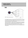
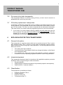
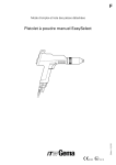
TRANSPONDER 3064 PRODUCT MANUAL Version: Draft 2012 v02 based on April 2007_V05.04.2007 Date: February 2015 2 PRODUCT MANUAL TRANSPONDER 3064 Contents 1 SAFETY INSTRUCTIONS _____________________________________________3 2 GENERAL INFORMATION ____________________________________________4 2.1 MODE OF OPERATION _________________________________________4 3 4 5 6 2.2 INCORPORATING THE TRANSPONDER IN DIFFERENT LOCKING SYSTEMS ___________________________________________________4 2.3 HIGHER-RANKING LOCKING LEVEL ______________________________5 SPECIAL DESIGNS __________________________________________________7 3.1 PASSWORD TRANSPONDER____________________________________7 3.2 3.3 3.4 SWITCH TRANSPONDER _______________________________________7 EXPLOSION PROTECTION TRANSPONDER (EX PROTECTION)________7 BONDED TRANSPONDER ______________________________________7 3.5 3.6 TRANSPONDER WITH INTEGRATED RFID CHIP ____________________7 FIRE SERVICE KEY TUBE TRANSPONDER ________________________8 3.7 G2 BATTERY REPLACEMENT TRANSPONDER _____________________8 EXPLOSION PROTECTION TRANSPONDER _____________________________8 4.1 GENERAL INFORMATION _______________________________________8 4.2 INDUSTRIAL STANDARDS ______________________________________8 4.3 CLASSIFICATION _____________________________________________8 ADDITIONAL FUNCTIONS ____________________________________________9 5.1 5.2 TIME ZONE CONTROL _________________________________________9 DATE OF VALIDITY ____________________________________________9 5.3 ACTIVATION TRANSPONDER ___________________________________9 BATTERY REPLACEMENT ___________________________________________10 6.1 BATTERY REPLACEMENT 3064_________________________________10 6.2 7 LOSS OF THE TRANSPONDER _______________________________________10 7.1 EMERGENCY OPENING _______________________________________10 7.2 8 9 BATTERY REPLACEMENT FOR EXPLOSION PROTECTION TRANSPONDER _____________________________________________10 REPLACEMENT TRANSPONDER [G1] ____________________________10 OVERVIEW OF DIFFERENCES BETWEEN G1 AND G2 PROTOCOLS ________11 DATABASE TRANSPONDER _________________________________________11 3 PRODUCT MANUAL TRANSPONDER 3064 1 SAFETY INSTRUCTIONS The transponder casing is protected against splash water. However, it is not watertight! Only use batteries which have been approved by SimonsVoss (see Section 9) The batteries used in Digital Locking Cylinder 3061 may pose a fire or burn hazard if handled incorrectly. Do not recharge, open, heat or burn these batteries. Do not short-circuit. Dispose of old and used batteries in the proper manner and store them out of children's reach! Damage may be caused to the transponder if you reverse the polarity. Do not touch the contacts on the new battery with your hands when replacing the old one. We recommend using cotton gloves free of fat or grease. When replacing the batteries, make sure that the electronics are not subject to mechanical load and are not damaged in any other way. Access through a door may be blocked due to defective or incorrectly programmed products. SimonsVoss Technologies GmbH is not liable for consequences of incorrect installation, such as blocked access to injured persons or those at risk, physical damage or any other losses. SimonsVoss Technologies GmbH accepts no liability for damage caused by incorrect fitting or installation. SimonsVoss Technologies GmbH reserves the right to make changes to the product or implement technical further developments without prior notice. This documentation has been compiled in accordance with the best knowledge available to us. However, errors cannot be ruled out. No liability is accepted in such cases. Should there be differences in the content of other language versions of this documentation, the German version applies in cases of doubt. 4 PRODUCT MANUAL TRANSPONDER 3064 2 GENERAL INFORMATION Transponder 3064 is a digital ‘key' which is programmed with locking plan software and functions using contactless, wireless communication. All functions are activated by pressing a button. These include authorisation identification and the opening and locking of doors, gates, barriers, furniture locks and similar elements. The transponder communicates with digital components - cylinders, Smart Relay and activation units - by sending and receiving continually changing crypto codes, which ensure that the system cannot be misused. As System 3060 functions using active transponder technology, the transponder features its own power source, a battery. This offers an advantage over passive technologies thanks to the lower power requirements in the cylinder and the greater operating range. SimonsVoss supplies different transponder models. These models are described in this document. The transponders are provided with two different firmware generations – G1 and G2. G2 features a more efficient communication protocol than G1. This will allow you to create larger, more efficient locking systems. Authorisations are written both on the locking cylinder and the transponder. This delivers greater flexibility in programming. A G2 system can also form a virtual network, i.e. authorisations and blocking lists are written on the transponder and transmitted into the locking system. This manual looks at the specific differences between transponders. Refer to the G2 manual for more detail. The G2 transponder features both the G1 and G2 protocols and can thus be programmed for both locking system generations. 2.1 Mode of operation To carry out an action, the transponder is held close to the digital lock (up to 40 cm for locking cylinders and 120 cm for Smart Relay) and then the transponder button is pressed. The transponder and the lock exchange key and authorisation data. The required action, such as opening or locking the door, can be carried out if the transponder is authorised for the digital lock. 2.2 Incorporating the transponder in different locking systems Each transponder can be used in three [G1] or four [G2] completely separate locking systems, providing that no areas of validity have been programmed. Each locking system receives its own password and is managed separately. 5 PRODUCT MANUAL TRANSPONDER 3064 Example: Company Branches Home 900 locks 85 locks 3 locks Locking System 1 Locking System 2 Locking System 3 Figure 1: A transponder for several separate locking systems 2.3 Higher-ranking locking level In order to create transponders which are to be authorised for more than three [G1] or four [G2] locking systems, higher-ranking locking levels need to be set up in such locking systems. A maximum of 3 higher-ranking levels can be created in a single locking system (green, blue and red). ! The red level is designed for security and safety services such as the fire service as these transponders can also open locks deactivated by a Block Lock function. ! A higher-ranking level is always reprogrammed at doors. 200 transponder IDs (TIDs) [G1] or 1024 [G2] are reserved per level in the LSM. Authorisations for different transponders in the higher-ranking locking levels may be different. 6 PRODUCT MANUAL TRANSPONDER 3064 Example: Company D Company C Company B Higher-ranking transponder Figure 2: Higher-ranking transponder Company A Main locking system Four companies are based in an office building with a main lock which is used by all the companies. Each company manages its own locking system with its own password. Each employee receives a transponder which is authorised for two locking systems, the main lock and their company's own system. The building management or on-site technicians and cleaning staff require access to all levels. The fire service, for example, requires a transponder which is authorised for all five locking systems in the building and also provides access if the alarm system is activated and the locking cylinders are deactivated by a Block Lock function. Higher-ranking locking levels are created in each of the five locking systems to provide access to all five locking systems. Each level receives the same password for all locking systems. 7 PRODUCT MANUAL TRANSPONDER 3064 3 SPECIAL DESIGNS 3.1 Password transponder Instead of being entered manually, the locking system password can be transmitted by radio using a special transponder. Standard transponders cannot be used as a password transponder. 3.2 Switch transponder For this type of transponder, a two-wire cable (about 1 m) is connected to the switch contacts on the button and fed to the outside. The transponder interconnects when the two wires are connected. Examples of use: 3.3 Linking third-party systems Remote activation of a digital locking cylinder or Smart Relay Explosion protection transponder (EX protection) This transponder features the same functions as Transponder 3064, but is also approved for use in Explosion Protection Zone 1 areas (please refer to Section 3 for further information). 3.4 Bonded transponder Bonded transponder This is a standard transponder as described above, but with a casing bonded to the transponder. This prevents the end user from misusing the transponder electronics or opening the casing. 3.5 Transponder with integrated RFID chip Transponders can be supplied with different integrated RFID chips as an option. These RFID Chips do not necessarily need to be programmed using the LSM programme. There is no logical connection between the active transponder and the passive RFID component. The following different technologies are offered: EM® 4102 HITAG® 1 HITAG® 2 MIFARE® Classic MIFARE® DESFire LEGIC® MIM256 LEGIC® ADVANT 128 8 PRODUCT MANUAL TRANSPONDER 3064 3.6 Fire service key tube transponder This transponder features a narrower casing (33 mm), so that it can be stored in a standardised fire service key tube safe. 3.7 G2 battery replacement transponder A G2 battery replacement transponder can be created in the LSM programme for G2 locking systems. This transponder can be used to deactivate freeze mode by activating it on the cylinder. The door can then be opened with an authorised transponder. This means there is no need to take the programming device to the lock concerned. ! In the case of an active battery warning, batteries are still used each time the door is opened. This may lead to the batteries being fully discharged if the transponder is not used for its intended purpose. The batteries must be replaced immediately in such cases. 4 EXPLOSION PROTECTION TRANSPONDER 4.1 General information This transponder is a special product which can be carried and used in Zone 1 potentially explosive areas. Zone 1 refers to an area where a potentially explosive atmosphere sometimes occurs during day-to-day operations. The following aspects must be taken into account: 4.2 The casing must not be opened. Only SimonsVoss Technologies GmbH may change the battery, unlike Standard Transponder 3064. As a general rule, users must comply with explosion protection regulations, such as the German Operating Regulations BGR132, when using the device. Industrial standards This transponder has been tested in accordance with applicable explosion protection standards. Refer to the following for further information: 4.3 Directive 94/9/EC DIN EN 60079-0 (Electrical equipment for potentially explosive atmospheres) DIN EN 60079-11 (Intrinsic safety 'i') Classification The transponder is classified as follows: Explosion Protection Zone 1 Intrinsic safety ib Explosion Group IIC Temperature class T3 9 PRODUCT MANUAL TRANSPONDER 3064 Equipment Group II2 G This applies to areas where a potentially explosive atmosphere may occur due to gases, vapours or mist. The information given refers to an ambient temperature between -20°C and +40°C in the area of use. 5 ADDITIONAL FUNCTIONS The following functions can be activated in the locking plan software: 5.1 Time zone control ZK transponder models can be programmed for digital locks, so that the transponders are only authorised for access at specific times. Such time zones are added to the locking plan software and the transponders are then allocated to the relevant time zone group. Example: 5.2 Mr Smith is issued the following authorisation: Monday to Friday 9 a.m.-6.30 p.m. Saturday 9 a.m.-12.45 p.m. Sunday No authorisation Date of validity Transponders can be programmed which feature a validity date for authorisation (also possible with a non-access-control model!): ! 5.3 Transponders which are valid from a specific point in time (e.g. as from 8 a.m. on July 12, 2013) Transponders which are valid until a specific point in time (e.g. until 5 p.m. on July 12, 2013) Transponders which are valid for a specific time period (e.g. between July 1, 2012 until July 31, 2014) A data set is created each time for the activation or expiry date. Activation transponder As the result of a Block Lock function, all authorised transponders are blocked for digital locks in a safety area when the alarm system is activated to prevent false alarms. Transponders can be programmed which eliminate this blocking mode and can thus be used in an emergency by the fire service, for example. The door can then only be opened using an authorised transponder. 10 PRODUCT MANUAL TRANSPONDER 3064 6 BATTERY REPLACEMENT 6.1 Battery Replacement 3064 The transponder battery can be replaced at any time when the battery warning is active (see Locking Cylinder 3061 Manual – Battery warning). Open the casing carefully, so that you can find the battery easily. Open the battery holder and remove the battery. Insert new battery and close battery holder. Press the casing back together again. When changing the battery, you must ensure that you do not take more than two minutes, that you do not press the transponder button during this time and that you do not cause a short circuit, otherwise you may cause data to be lost. 6.2 Battery replacement for explosion protection transponder ! Only SimonsVoss Technologies GmbH may replace the battery in this transponder. 7 LOSS OF THE TRANSPONDER 7.1 Emergency opening An emergency opening may be carried out with the Smart CD and PDA and by entering the locking system password. 7.2 Replacement transponder [G1] If a transponder is lost, it can be blocked in the locking plan and a replacement transponder added. If the locking system is operated in overlay mode [G1], the lost transponder is blocked automatically as soon as the replacement transponder is activated at the digital lock (see Software Operating Instructions for programming and procedure). 11 PRODUCT MANUAL TRANSPONDER 3064 8 OVERVIEW OF DIFFERENCES BETWEEN G1 AND G2 PROTOCOLS Locks per locking cylinder on a transponder Number of locking systems Max. number of TIDs per higher-ranking locking level Time zone groups Physical access lists storable Locking plan information G1 16,000 G2 64,000 3 4 [G2] + 3 [G1] 200 1024 5+1 n/a Locks 100 + 1 1000 Transponders or locks Table 1. Transponder differences between G1 and G2 9 DATABASE TRANSPONDER Casing Material Polyamide Colours Diameter Height Weatherproof plastic Black casing, button in different colours 42.0 mm 13.7 mm Ambient conditions Temperature range: -20ºC to +60ºC Protection rating: IP65 IP66 (.SPEZ version) Environmental Class III Batteries Type Manufacturer Quantity Voltage Battery life CR 2032 Varta, (Panasonic, Sony) 1 unit 3 volts G1: up to 100,000 operations or up to 10 years on standby G2: up to 400,000 operations or up to 10 years on standby