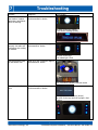
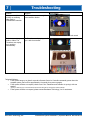
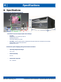
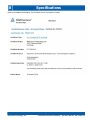
1
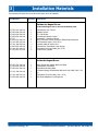
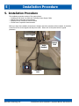
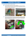
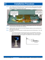
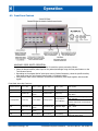
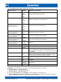
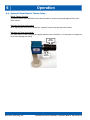
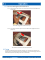
Installation / Operation Manual
CinemaVision
Resonance Technology, Inc.
18121 Parthenia Street
Northridge, California 91325, USA
+1 (818) 882-1997
+1 (800) 428-MRTV
www.mrivideo.com
Innovative MRI-Compatible Entertainment Systems
Advanced Functional MRI Systems
Resonance Technology, Inc.
CinemaVision System Installation / Operation Manual: RTC-CV Rev 14
Notice:
This document contains proprietary information protected by copyright. All rights reserved.
No part of the document may be photocopied or reproduced without the prior written consent of Resonance
Technology, Inc. Information contained in this document is covered by one or more of the following U.S. patents:
5627902, 5877732, 5432544, 5412419.
Resonance Technology, Inc.
CinemaVision System Installation / Operation Manual: RTC-CV Rev 14
Table of Contents
1. Introduction ......................................................................................... 1
2. Safety Information............................................................................... 2
2.1.
Important Warnings for Patient and Operator Safety ................................................................ 2
2.2.
Precautionary Patient Conditions................................................................................................ 2
2.3.
Use Restrictions........................................................................................................................... 3
2.4.
MRI Environment Hazards........................................................................................................... 3
2.5.
General Warnings for Electronic Products .................................................................................. 4
2.6.
Labeling Used to Indicate Device Safety..................................................................................... 4
2.7.
Medical Device Safety Approvals................................................................................................. 5
3. Installation Materials ........................................................................... 6
4. Room Layout Overview for Installation ............................................... 8
5. Installation Procedure ....................................................................... 10
5.1.
Installing the MR Laser Link Cable and Transducer Power Supply Cables ............................... 11
5.2.
Magnet Room Component Interconnection .............................................................................. 12
5.3.
Equipment Room Component Interconnection ......................................................................... 15
5.4.
Control Room Component Interconnection .............................................................................. 15
6. Operation ........................................................................................... 20
6.1.
CinemaVision System Features ................................................................................................. 20
6.2.
Front Panel Controls .................................................................................................................. 21
6.3.
Technologist Remote Control .................................................................................................... 22
6.4.
Optional Patient Monitor Camera Setup.................................................................................... 24
6.5.
Patient Setup ............................................................................................................................. 25
6.5.1.
6.5.2.
6.5.3.
6.5.4.
6.6.
Overview..................................................................................................................................25
Audio Setup .............................................................................................................................25
Video Setup .............................................................................................................................25
How to fit the Video Goggles into the 8-channel head coil ..................................................26
Cleaning ..................................................................................................................................... 26
7. Troubleshooting ................................................................................. 28
8. Specifications ..................................................................................... 32
9. Support Information .......................................................................... 34
Resonance Technology, Inc.
CinemaVision System Installation / Operation Manual: RTC-CV Rev 14
Resonance Technology, Inc.
CinemaVision System Installation / Operation Manual: RTC-CV Rev 14
1
Introduction
1. Introduction
Congratulations on your purchase of the CinemaVision system for patient comfort. This device represents more than
40 years of development and state-of-the-art engineering. We are confident this product will give you the tools you
need for comforting the patient while undergoing MRI scans.
This installation/operation manual outlines how to properly install and operate the system.
Thank you for choosing to purchase this system from Resonance Technology, Inc., the leader in fMRI and MRI
patient comfort systems.
Suggestions on how to improve this system are always welcome.
Sincerely,
Mokhtar Ziarati
President and CEO
Resonance Technology, Inc.
Page 1
Resonance Technology, Inc.
CinemaVision System Installation / Operation Manual: RTC-CV Rev 14
2
Safety Information
2. Safety Information
At Resonance Technology, Inc., patient safety is our top priority. Please review this section completely as its contents
are vital to the safety of the installer, the clinician/operator, and the patient.
2.1. Important Warnings for Patient and Operator Safety
WARNING
Prior to every use, inspect all system components that come in contact with the patient.
Discontinue product usage immediately if any damage is evident or presents other potential
hazards. Use of damaged components may cause injury to the clinician or the patient.
Examples of hazardous damage include but is not limited to the following:
• Protective lenses missing from the video goggles
• Cracked housing on video goggles or audio headset
• Microphone boom separated from headset housing (exposing wires)
• Cable padding torn, exposing cable inside
• Any damage potentially exposing wires to the patient
2.2. Precautionary Patient Conditions
Eye Disease / Eye Injury / Glaucoma
If the patient has been diagnosed with or is susceptible to eye disease, eye injuries, or glaucoma, instruct the
patient to consult their doctor before using the video goggles. Use of this product by individuals with
conditions such as glaucoma is not recommended.
Heart Disease / High Blood Pressure
If the patient has a history of heart disease or high blood pressure, instruct the patient to consult their doctor
before using this system. If during viewing any increased anxiety is experienced, stop using this product
immediately and instruct the patient to rest. If the symptoms persist after resting, instruct the patient to
consult their doctor before continuing using this product.
Seizures
If the patient has a history of temporary spasms, unconsciousness, or epileptic seizures from light
stimulation, instruct the patient to consult their doctor before using this system. Use of this product by such
individuals may cause spasms, unconsciousness, or seizures. If the patient experiences such symptoms, stop
using the product immediately and instruct the patient to consult their doctor.
Sickness / Headache / Nausea
If during use, the patient experiences any of the following symptoms, stop using this product immediately
and rest. These symptoms may indicate misuse or overuse of the product or that you should not use the
product for health reasons. If the following symptoms persist after rest, consult your doctor.
• Sore eyes, eye fatigue, or double vision
• Headache
• Inability to focus on the screen
• Stiff or sore shoulders or neck
For patient safety, the patient video goggles turn off automatically after six hours of continuous use. Read
this user manual for instructions on how to reset the video goggles to continue viewing video images.
Motion Sickness from using the Video Goggles
Some patients may experience motion sickness, headache, or nausea from viewing visual paradigms or video
programs, especially those with intense action and movement. If the patient experiences any of these
symptoms, stop using the product immediately. To avoid personal injury or injury to others, do not operate a
motor vehicle nor do anything that requires concentration until these symptoms disappear.
Page 2
Resonance Technology, Inc.
CinemaVision System Installation / Operation Manual: RTC-CV Rev 14
2
Safety Information
Loud Sound Volume
Avoid using audio headset with high volume for the patient as hearing expert’s advice against continuous
loud and extended audio play. If the patient experiences a ringing in their ears, reduce the audio headset
volume. The patient is advised to consult their health doctor for further advice.
2.3. Use Restrictions
Shelf-Life and System Maintenance Service Schedule
The CinemaVision System comes with a one year original manufacturer warranty and a shelf life of two years
from the date of installation. Optional extended warranty may be purchased for this system. With patient
safety in mind, Resonance Technology, Inc. recommends periodic maintenance service for this CinemaVision
System every six months after the one year original warranty period.
Restrictions on Using Non-Resonance Technology, Inc. Components with the CinemaVision system
The original manufacturer’s warranty will be voided if any non-Resonance Technology, Inc. Power Supply is
used to provide power the CinemaVision Transducer. The original manufacturer’s warranty will be voided if
other non-Resonance Technology, Inc. approved components are connected to the CinemaVision system. In
addition, Resonance Technology, Inc. cannot be held responsible or liable for any unauthorized use of this
equipment. If you have any questions about how to operate this system, please read this user manual or call
Resonance Technology, Inc. customer service at (818) 882-1997 or email [email protected].
2.4. MRI Environment Hazards
Installation of materials inside the MRI suite must be done with extreme caution and only by authorized
personnel. Care must be taken to keep ferromagnetic materials such as tools, filter plates, screws, etc. at
least three meters (approximately 10 feet) away from the energized magnet. Absolutely no work should be
done near the filter panel when a scan is in progress.
All cabling inside the MRI environment should either be connected or terminated properly. Failure to do so
may result in skin burns related to RF energy. All cables should be run straight and never looped, as this
may also cause serious skin burns inside the MRI room.
In addition, no persons with ferromagnetic prosthetic devices such as pacemakers or joint replacements
should enter the MRI suite at any time. Extremely high magnetic forces have the potential to dislodge
ferrous items at high velocities that can result in serious injury or death.
Only system components explicitly designated for use in the MRI suite should be placed inside the MRI suite.
Components not designated for use inside the MRI suite may present a projectile hazard and can become
airborne, causing property damage, serious bodily injury, or death. Please refer to the installation block
diagram to determine which components belong inside the MRI suite.
Resonance Technology, Inc. will not be held liable for any injuries or property damage which may occur as
the result of improper use or installation of this product. By agreeing to this notice, users certify that they
are familiar with basic safety procedures in an MRI room environment and that they have read and
understand these safety precautions.
For questions regarding installation procedures or this manual, Resonance Technology, Inc. technical support
staff may be reached Monday through Friday 8 a.m. to 5 p.m., Pacific Standard Time at (818) 882-1997, or
by email at [email protected].
Page 3
Resonance Technology, Inc.
CinemaVision System Installation / Operation Manual: RTC-CV Rev 14
2
Safety Information
2.5. General Warnings for Electronic Products
Electric shock
Failure to observe all operating and maintenance instructions may cause damage to this product and may
result in property damage and/or injury or death from electric shock, fire, or other cause.
To avoid the risk of electric shock or fire hazard, a multi-outlet power strip or extension cord should not be
connected to the video monitor socket outlet on the CinemaVision controller. This socket outlet should only
be used to power the CinemaVision video monitor provided with the system.
Do not disassemble this product.
Only Resonance Technology, Inc. trained and authorized personnel should perform all required service for
this product. Failure to comply with this warning may result in property damage, injury and/or death from
electric shock, fire, or other cause.
Avoid exposing this product to extreme environments.
This product may be damaged by high temperatures, direct sunlight exposure, by dropping this product, or
by other mechanical shock. Do not expose this product to rain or excessive moisture. Avoid these conditions
as the video goggle lenses may become damaged and may result in eye fatigue to the patient.
Unplug this product when not in use for long periods of time.
Always unplug this product when not in use for extended periods of time or during MRI maintenance. Leave
connected if used daily. In addition, to prolong the life of the video goggle, use the Technologist Remote to
turn off the power to the video goggle at night or when not in use. Note that if the system is not used for 2
hours, it will hibernate and you may have to press the Tech Remote TALK button to wake up the system.
2.6. Labeling Used to Indicate Device Safety
Type BF Applied Part
Devices that have conductive contact with the patient or have applied parts that are fixed in
medium or long term contact with the patient.
MR-Safe Device
Device considered safe for use anywhere inside the magnet room.
MR Conditionally-Safe Device
Device considered safe in the MR room under certain conditions.
MR Unsafe Device
Device considered unsafe for use in the MR room. These items should not be taken inside the
MR room due to being a projectile hazard in the magnetic field.
Page 4
Resonance Technology, Inc.
CinemaVision System Installation / Operation Manual: RTC-CV Rev 14
2
Safety Information
2.7. Medical Device Safety Approvals
The CinemaVision System has the following safety certifications:
Page 5
Resonance Technology, Inc.
CinemaVision System Installation / Operation Manual: RTC-CV Rev 14
3
Installation Materials
3. Installation Materials
Your CinemaVision system comes complete with all the necessary components to complete the system installation at
your facility. The following checklist is provided for materials verification purposes:
Part Number
Quantity
Photo
Description
RTC-550-010-000-001
1
CinemaVision Controller Unit
RTC-650-040-000-000
1
Speaker System
RTC-551-070-124-000
1
Video Goggle with Rubber Mask and Strap
RTC-650-060-000-000
1
Soft Shell Headphone w/ Microphone
RTC-550-050-000-000
1
CinemaVision Transducer
RTC-650-050-005-000
1
CinemaVision Transducer Power Supply
RTC-650-030-000-000
1
15" LCD Monitor with power supply
RTC-650-020-000-000
1
Technologist Remote Control
RTC-CV
1
Installation / Operation Manual (This manual)
RTC-650-070-060-000
1
Set of Corrective Lenses, optional (Offered Upon Request)
RTC-650-050-182-000
1
Transducer Mounting Plate (specific to your magnet type)
RTC-ALS-HEC
50
Headset Earpiece Covers
RTC-ALS-TWR
50
Tie Wraps
RTC-ALS-TWH
20
Tie Wrap Holders
RTC-651-000-453-000
1
Custom Headrest (for 8-channel coil) to fit audio headset
RTC-550-010-474-000
1
Remote Controls for Television
RTC-650-300-605-000
1
9-pin D-Sub Filter
RTC-ALS-HDH
2
Headset Hooks
RTC-550-010-477-000
RTC-650-020-606-000
RTC-650-010-235-000
ATS300SP
1
4
1
1
Control Room Camera
Batteries (AAA)
Remote Control for DVD
“T” – Antenna (TV/FM)
RTC-101-108-001-000
1
8-Channel MR Laser Link Cable
RTC-101-245-001-001
1
Transducer DC Power cable – 15 meters (~50’)
RTC-101-210-001-001
1
Transducer DC Power cable – 3 meters (~10’)
RTC-101-950-003-000
1
RG-59, 75 ohm Antenna cable – 10 meters (~35’)
RTC-101-306-003-000
RTC-101-303-003-000
2
1
Hospital Grade AC Power Cord
Power Cord Male/Female (for monitor)
Page 6
Resonance Technology, Inc.
CinemaVision System Installation / Operation Manual: RTC-CV Rev 14
3
Installation Materials
The following list shows the rooms where the items are to be installed.
Part Number
Quantity
Description
Outside the Magnet Room:
In the technologist room or near the penetration panel
RTC-551-010-000-000
RTC-650-040-000-000
RTC-650-030-000-000
RTC-650-020-000-000
RTC-CV
RTC-650-070-060-000
RTC-101-950-003-000
RTC-101-306-003-000
RTC-650-050-005-000
RTC-101-210-001-001
RTC-550-010-477-000
1
1
1
1
1
1
1
2
1
1
1
CinemaVision A/V Console
Speaker System
15" LCD Monitor
Technologist Remote Control
Installation / Operation Manual
Set of Corrective Lenses, optional (Offered Upon Request)
RG-59 Antenna cable (10m /35 ft)
Hospital Grade AC Power Cord
CinemaVision Transducer Power Supply
Transducer DC Power Cable (3m /10 ft)
Control Room Camera
Inside the Magnet Room:
RTC-551-070-124-000
RTC-550-050-000-000
RTC-650-050-182-000
1
1
1
RTC-101-108-001-000
1
RTC-101-245-001-001
RTC-650-060-000-000
1
1
Video Goggle with Rubber Mask and Strap
CinemaVision Transducer
Transducer Mounting Plate
8 Channel Orange CinemaVision MR Laser Link Cable (50m / 150
ft)
Transducer DC Power cable (15m / 50 ft)
Soft Shell Headphone w/ Microphone
Page 7
Resonance Technology, Inc.
CinemaVision System Installation / Operation Manual: RTC-CV Rev 14
4 Room Layout Overview for Installation
4. Room Layout Overview for Installation
WARNING: Absolutely no ferromagnetic tools should be brought inside the MRI Suite!
While no tools, other than tie wraps, are required to install the system in the MRI suite, absolutely all ferromagnetic
tools remain outside of, and away from the door leading to, the MRI suite.
Below is a typical MRI setup. Your individual installation may vary somewhat, but it will generally be spaced into
three areas: Control Room, Computer/Equipment Room and MRI Suite or Magnet Room.
The Control room setup consists of placement and connection of the CinemaVision Controller, Technologist Remote
Control, and LCD video monitor. Additional auxiliary audio/video sources such as an iPod®, iPhone®, MP3 player,
satellite receiver, or external DVD player may be connected.*
The Magnet room setup includes a single Laser Link cable bundle that will be connected from the CinemaVision
Controller unit through the filter panel wave-guide to the CinemaVision Transducer in the Magnet Room. With the
exception of the audio headset and visor goggles, all the Magnet Room components of the CinemaVision must be
installed to the side of the magnet shroud and never in line with the bore. Additionally, these components should be
placed in an area not heavily trafficked to keep them from being damaged.
* “iPod” and “iPhone” are registered trademarks of Apple Inc.
Page 8
Resonance Technology, Inc.
CinemaVision System Installation / Operation Manual: RTC-CV Rev 14
4 Room Layout Overview for Installation
Magnet Room
Control Room
LCD Video Monitor
Audio Headset
Video Goggles
Tech
Remote
Patient Monitoring
Camera
Control
Room
Camera
A/V Console
(Optional)
Penetration
Panel
Wave
Guide
8-channel Fiber
Optic Cable
(50m / 150’)
Transducer
Transducer
Power Cable
Transducer
Power Cable
(15m / 50’)
(3m / 10’)
Transducer
Power Supply
Must be placed outside the
magnet’s 20-Gauss line
Page 9
Resonance Technology, Inc.
CinemaVision System Installation / Operation Manual: RTC-CV Rev 14
5
Installation Procedure
5. Installation Procedure
The installation procedure consists of four major phases:
• Installing the MR Laser Link Cable and Transducer Power Supply Cables
• Magnet Room Component Interconnection
• Equipment Room Component Interconnection
• Control Room Component Interconnection
Before you begin the installation, determine the location where the transducer will be installed. It should be
a secure area next to the magnet and away from traffic. Please refer to the photo below for typical
placement:
Video Goggles
Audio
Headset
Patient
Bed
Transducer
Unit
Page 10
Resonance Technology, Inc.
CinemaVision System Installation / Operation Manual: RTC-CV Rev 14
5
Installation Procedure
5.1. Installing the MR Laser Link Cable and Transducer Power Supply Cables
The preferred method of routing the fiber optic cable is to run the cable from the control room through the
overhead ceiling drop tiles and down into the computer room in front of the filter panel through the Fiber
Optics Waveguide. It can then be run alongside the other MRI cables going to the magnet. The cable should
end where you intend to locate the transducer.
Note: Care must be taken to ensure the cable is not bent in radius of less than 15cm (6
inches) or damage to the optical fibers will occur.
MR Laser Link Cable
MR Laser Link Cable
r
r ≥ 15 cm
r
r < 15 cm
The routing of the transducer power cables will vary somewhat depending on the facility layout and the
magnet type. For most facilities and magnets, the typical procedure would be as follows:
5.1.1.
Determine the length of cable needed from the location of the transducer to the penetration panel.
If the run needed is longer than 3 meters (10 feet), then use the 15-meter (45-foot) transducer
power cable in the magnet room. The 3-meter cable will then be used in the computer/equipment
room.
5.1.2.
If there is a blank filter plate on the penetration panel, and a matching panel with DB-9 cut-out has
been provided, install the DB-9 low-pass filter such that the transducer power cables will mate with
the filter on both sides. If the filter was pre-installed, you will need to inspect the orientation to
ensure the cables will mate. In some cases it may be necessary to remove the filter and re-install it
in the opposite direction. Remove the blank filter plate and install the new one containing the DB-9
filter.
If there is not a blank filter plate available, look for an available DB-9 filter that may be installed
elsewhere on the penetration panel. If one is available, verify the polarity to ensure the transducer
cables will mate. Again, it may be necessary to reverse the direction of the filter.
If no free filters are available, then a new DB-9 cut-out will need to be punched into the penetration
panel or plate. Please check with the facility for permission and preference to the filter’s location.
5.1.3.
Route the transducer power cable that will be used in the magnet room, following a similar path to
the fiber optic cable. Avoid running the power cable close to the high-energy RF cables for
the magnet, as the RF energy may interfere with reliable operation of the system. Connect the
DB-9 connector of the cable to the DB-9 filter.
5.1.4.
In the computer/equipment room, choose a site for the transducer power supply that will be
convenient to the operator. Route the remaining transducer power cable from the power supply
location to the penetration panel. Connect the DB-9 cable to the same DB-9 filter that the other
transducer power cable is connected to.
Page 11
Resonance Technology, Inc.
CinemaVision System Installation / Operation Manual: RTC-CV Rev 14
5
Installation Procedure
5.2. Magnet Room Component Interconnection
5.2.1.
Remove both upper and lower cable covers from the transducer.
5.2.2.
Unravel all the fiber optic cables from the plastic coil. Select the red (#1), green (#2), blue (#3),
black (#4), and brown (#5) connectors. Put the unused fibers back into the plastic coil. Remove
the plastic dust caps from the five selected fiber optic connectors. Keep the dust caps for future use
whenever cables might be removed for service.
5.2.3.
Remove the dust caps on all the fiber optic connectors on the transducer. Matching the fiber optic
connector colors with the labels on the transducer, align the ridge on the cable connector with the
notch of the transducer’s connector. Insert the fiber optic cable connector until fully seated, then
gently turn the ring clockwise until it stops (approximately one quarter turn). Perform the same
procedure on the remaining fiber optic cables.
Page 12
Resonance Technology, Inc.
CinemaVision System Installation / Operation Manual: RTC-CV Rev 14
5
Installation Procedure
5.2.4.
Secure the fiber optic bundle strain relief to the transducer housing. Make sure all of the individual
fiber optic cables have a smooth bend radius. The fiber optics can be damaged if bent too tightly.
Fold the protective tape over the fiber optic cables.
Rubber grommet
used to secure the
fiber optics bundle
Put the spare unused
fiber cables back in
the plastic coil.
Protective
tape
5.2.5.
Connect the Power Supply cable to the Transducer. Route the cable to one of the round notches
near where the fiber optic bundle exits the housing.
5.2.6.
Carefully install the lower cable cover over these connections, making sure not to pinch any of the
cables under the screw posts.
5.2.7.
If the patient monitoring camera option is included, please perform the following steps. If not, skip
to Step 5.2.8.
The MRI/CAM 2020 patient monitoring camera option of the CinemaVision system allows
doctors and technologists to monitor patients undergoing MRI scans. This color camera is
MRI-safe and installed inside the magnet room typically on the wall behind the magnet.
Page 13
Resonance Technology, Inc.
CinemaVision System Installation / Operation Manual: RTC-CV Rev 14
5
Installation Procedure
5.2.7.1.
Use the included non-magnetic screws to attach the patient camera to the back wall behind
the magnet.
WARNING: Never use any metal screws that might be attracted by the
magnet as they may become projectiles and cause serious injury or death
to anyone inside the magnet room. Remember that the magnetic field is
always present.
5.2.7.2.
Connect the 4-pin camera power/signal cable to the camera, and route the cable to the
transducer.
WARNING: Avoid creating loops in the cable as it may cause MRI image
noise. Also, make sure to route the cable away from walkways inside the
magnet room.
5.2.8.
Connect audio headset and video goggle to transducer. Each latching connector should “click” on
both sides when fully seated. If the headset connection is equipped with a DB-9 connector, make
sure the screws on the sides of the connector are secure.
5.2.9.
Carefully install the upper cable cover, making sure to align all cables with their respective exit
notches in the housing, and making sure no cables are pinched while installing the cover.
Page 14
Resonance Technology, Inc.
CinemaVision System Installation / Operation Manual: RTC-CV Rev 14
5
Installation Procedure
5.3. Equipment Room Component Interconnection
5.3.1.
Place the Transducer power supply into the location chosen in Step 5.1.4. This location must be
outside of the 20-Gauss line.
5.3.2.
Connect the round transducer power cable connector to the power supply. Make sure the ring on the
connector is secure.
5.3.3.
Make sure the power supply’s switch is set to the “OFF” position. Connect a hospital-grade AC power
cable to the AC inlet connector, and to an available AC outlet in the computer/equipment room.
5.4. Control Room Component Interconnection
The photo below depicts a typical control room setup.
Video Monitor
Tech
Remote
Control
CinemaVision
A/V Controller
Page 15
Resonance Technology, Inc.
CinemaVision System Installation / Operation Manual: RTC-CV Rev 14
5
Installation Procedure
The photo below shows an overview of the CinemaVision A/V Console rear panel.
5.4.1.
Unravel all the fiber optic cables from the plastic coil. Select the red (#1), green (#2), blue (#3),
black (#4), and brown (#5) connectors. Put the unused fibers back into the plastic coil. Remove the
plastic dust caps from the five selected fiber optic connectors. Keep the dust caps for future use
whenever cables might be removed for service.
5.4.2.
Remove the dust caps on all the fiber optic connectors on the controller. Matching the fiber optic
connector colors with the colored rings on the controller, align the ridge on the cable connector with
the notch of the controller’s connector. Insert the fiber optic cable connector until fully seated, then
gently turn the ring clockwise until it stops (approximately one quarter turn). Perform the same
procedure on the remaining fiber optic cables.
Page 16
Resonance Technology, Inc.
CinemaVision System Installation / Operation Manual: RTC-CV Rev 14
5
Installation Procedure
5.4.3.
Connect the S-video and composite video (RCA) cables from the VIDEO MONITOR section to the LCD
monitor.
5.4.4.
Connect the monitor power supply to the LCD monitor and to the VIDEO MONITOR AC OUT
connector.
5.4.5.
Connect the Tech Remote Control to the TECH REMOTE connector.
5.4.6.
Connect the Control Room Camera to the CONTROL ROOM CAMERA connector. Please note the
connector only fits one way. The rib on the connector points to the left.
5.4.7.
Connect the Audio Speaker cables.
5.4.8.
Make sure the Controller power switch is in the off position. Connect the Hospital Grade
Power Cord to the Controller and an available active AC power outlet.
5.4.9.
Insert the strain relief of the fiber optic cable into the square notch in the side panel, using the side
which is the most convenient for the layout of the desk area. Place the other cables into the round
notches, using the side which is the most convenient. The photo below shows a typical arrangement.
5.4.10. Power on the LCD Monitor and then power on the Controller.
5.4.11. Power on the Transducer Power Supply, usually located in the computer room. (Exact location will
vary depending on installation and magnet type.) The logo rings on the CinemaVision Controller and
Transducer should start rotating within 30 seconds of both units being powered up.
Page 17
Resonance Technology, Inc.
CinemaVision System Installation / Operation Manual: RTC-CV Rev 14
5
Installation Procedure
5.4.12. Use the included plastic tie wraps to secure all cables connected to the back of the CinemaVision
Controller to prevent accidental disconnection.
5.4.13. Install the rear cable cover once all functions are verified to be working.
Page 18
Resonance Technology, Inc.
CinemaVision System Installation / Operation Manual: RTC-CV Rev 14
Page 19
Resonance Technology, Inc.
CinemaVision System Installation / Operation Manual: RTC-CV Rev 14
6
Operation
6. Operation
Below is a description of the CinemaVision control room components. The Controller converts the selected
audio and video source signals into optical signals that the MR Laser Link cables route to the Transducer unit
inside the magnet room. The Transducer unit recreates the signals and routes the audio and video signals to
the audio headset and video goggles.
LCD Video
Monitor to
view the
selected video
source.
The Tech
Remote unit
allows
control of all
system
features
The
CinemaVision
Controller unit
6.1. CinemaVision System Features
• Fiber optic link cable for audio, video, and data/voice communication between CinemaVision Controller in
the control room and Transducer in the magnet room
• Technologist Remote Control with a highly visible display to select all system features
• 15-inch LCD monitor and speaker system with subwoofer to view and hear the selected control room
audio and video sources
• Built-in DVD player with the ability to play DVD video, standard CD audio, MP3 audio, MPEG video, photo
CD, etc.
• Built-in AM/FM tuner to listen to available radio stations.
• Built-in digital TV tuner, capable of receiving 256-QAM digital cable or ATSC digital TV broadcast, received
via standard 75-Ohm coaxial cable connection.
• Auxiliary input jacks allow a variety of external audio/video sources, such as iPod®, iPhone®, satellite
receiver, etc.*
• Independent audio/video source selection for the control room and magnet room
• Control room camera so patient can see the clinician/technologist or parent(s) (for pediatric scans) during
the MRI scan session
• Patient stereo headset with communication microphone and patient-controlled alert button
• LCD video goggles for patient to view video images. Image presented to patient is the equivalent to
viewing a 62-inch screen at a distance of 5 feet, giving the impression of being in a private movie theater.
• (Optional) Patient monitoring with the use of an MRI-safe video camera located inside the magnet room
in an area where the technologist may not have a clear line of sight through the control room window
• Simple patient setup to prevent downtime.
* “iPod” and “iPhone” are registered trademarks of Apple Inc.
Page 20
Resonance Technology, Inc.
CinemaVision System Installation / Operation Manual: RTC-CV Rev 14
6
Operation
6.2. Front Panel Controls
AUXILIARY VIDEO INPUTS OPERATION:
In order to use the Auxiliary Video Inputs in the CinemaVision system proceed as follows:
• Select the desired auxiliary video input for the patient/technologist using the front panel buttons or the
Tech Remote Control.
• Depending on the selected kind of video input source (S-video/Composite), select the specific Auxiliary
video input using the Tech Remote Control wheel #4 (rightmost wheel).
• Verify that the video source selected is connected to the Auxiliary video input together with the audio
signals.
Front Panel Arrow Key Functions:
A/V Console
Operator Selection
Up (↑) Key
Down (↓) Key
Left (←) Key
Right (→) Key
Center (O) Key
Camera
[No function]
[No function]
[No function]
[No function]
[No function]
TV
Channel Up
Channel
Down
Volume Down
Volume Up
TV Setup Menu
Cursor Up
Cursor Down
Change Option
Change Option /
Enter submenu
DVD
DVD Menu Up
DVD Menu Left
DVD Menu Right
Enter / Select
AM/FM
Manual Tune
Up
DVD Menu
Down
Manual Tune
Down
Seek Down
Seek Up
Change Band (AM/FM Select)
AUX
[No function]
[No function]
[No function]
[No function]
Toggle between S-Video &
Composite Video Inputs
Press and Hold for 5 Sec: Enter TV
Setup Menu
Press and release: Change Option /
Enter submenu
Press and hold for 5 sec: Return to
previous menu level, or exit menu if
at top level
Page 21
Resonance Technology, Inc.
CinemaVision System Installation / Operation Manual: RTC-CV Rev 14
6
Operation
6.3. Technologist Remote Control
Wheel #1 - Controls the patient headset audio level.
Scrolling the wheel up increases the headset volume.
Scrolling the wheel down decreases the headset volume.
Scrolling the wheel down while pressing down on the Menu wheel (#4) mutes the headset.
Scrolling the wheel up while pressing down on the Menu wheel (#4) un-mutes the headset. (Previous
volume setting is resumed.)
Wheel #2 - Controls the Patient Microphone audio level.
Scrolling the wheel up increases the patient microphone volume.
Scrolling the wheel down decreases the patient microphone volume.
Scrolling the wheel down while pressing down on the Menu wheel (#4) mutes the microphone.
Scrolling the wheel up while pressing down on the Menu wheel (#4) un-mutes the microphone. (Previous
volume setting is resumed.)
Wheel #3 - Controls the system audio level.
Scrolling the wheel up increases the control room volume.
Scrolling the wheel down decreases the control room volume.
Scrolling the wheel down while pressing down on the Menu wheel (#4) mutes the control room speakers.
Scrolling the wheel up while pressing down on the Menu wheel (#4) un-mutes the control room speakers.
(Previous volume setting is resumed.)
Wheel #4 - Controls the system settings:
Clicking the wheel enters the system menu.
Scrolling the wheel up or down rotates through the system functions.
To select a desired menu function, press down on the wheel.
To select sub-menu functions scroll the wheel up/down and press down again.
Technologist Remote Control with built-in microphone volume adjustment – Push and hold the talk button then
scroll up or down the adjustment wheel #1. This adjustment is to change the tech remote built-in microphone volume
that the patient will hear during the two-way channel communication.
Page 22
Resonance Technology, Inc.
CinemaVision System Installation / Operation Manual: RTC-CV Rev 14
6
Operation
The Tech Remote Control system functions are as follows:
Menu Functions
Option
Patient A/V
DVD*
AUX
Camera
TV
Radio
DVD*
Aux
Camera
TV
Radio
Control Room AV
DVD Control
(if DVD is the selected source for
Patient or Control Room)
TV Channel
(if TV is the selected source for
Patient or Control Room)
Radio Station FM Tuner
(if Radio is the selected source for
Patient or Control Room)
Radio Station AM Tuner
(if Radio is the selected source for
Patient or Control Room)
Aux Input
(if AUX is the selected source for
Patient or Control Room)
Patient Volume Balance
Communication Mode
Full Duplex
Selects the Audio/Video for the Patient.
Selects the Audio/Video for the Control Room.
Play
Exit
Previous
Next
Pause
Stop
Up
Exit
Down
Next
Exit
Previous
Next
Exit
Previous
Automatic*
S-Video
Composite
Bar Graph
Auto
Manual*
Off
On*
Tech Camera
Manual
Auto*
Visor Power
On*
Off
On*
Off
A/V Console
Transducer
Tech Remote
Exit Menu
System Power
System Information
Exit Menu
Description of Function
Controls the Functions of the DVD player.
Controls the Scrolling of TV channels.
Controls the Scrolling between radio stations.
Controls the Scrolling between radio stations.
Selects the Type of Video Signal being fed through the AUX input
connector.
Used to balance the Audio on the Patient Headset.
Selects the Type of Connection between Controller and Patient.
Enables patient microphone in the Control Room even when Talk
button is pressed, so both patient and technologist can speak and
hear each other at the same time. Turn this off if there is a problem
with feedback.
If set to “Auto”, control room camera is automatically connected to
patient video when Talk button is pressed. Patient video changes
back to previous source when Talk button is released
Controls the Power Supplied to the patient video visor.
Controls the Power Supplied to CinemaVision Controller and
Transducer.
Displays hardware version, firmware version, and serial number of
selected device.
Exits menu.
*Default Settings
Please Note: To reset the system to the original Factory Default Settings, perform the following:
1. Adjustment Wheel #1 - Set Patient Audio to 1
2. Adjustment Wheel #2 - Set Patient Microphone to 2
3. Adjustment Wheel #3 - Set System Audio to 3
4. Press and hold the Talk button for 15 seconds. Wait for the display to count down to zero.
5. Release the TALK button and wait for the system to re-synchronize. Both the CinemaVision Controller and Transducer
front panel logo lights should have color lights rotating once synchronized.
Page 23
Resonance Technology, Inc.
CinemaVision System Installation / Operation Manual: RTC-CV Rev 14
6
Operation
6.4. Optional Patient Monitor Camera Setup
Patient Camera Controls:
The patient camera model MRI/2020 comes with automatic Iris control and manually adjusted Focus and
Zoom controls.
Adjusting the Focus lens control:
When adjusting the focus for the camera lens, rotate the control to get the best picture clarity.
Adjusting the Zoom lens control:
The Zoom control is used to magnify the specific target the lens is focused on. You may have to re-adjust the
focus when changing this setting.
ZOOM
CONTROL
FOCUS
CONTROL
Page 24
Resonance Technology, Inc.
CinemaVision System Installation / Operation Manual: RTC-CV Rev 14
6
Operation
6.5. Patient Setup
6.5.1.
Overview
Make sure all cables have been connected securely to the Transducer in the Magnet Room and that
the system components do not impede any walkways. Ensure that the Transducer is not placed
directly in front of the bore of the magnet. Before placing the Video Goggles and Headphones on the
patient, make sure that the microphone audio levels on the Control Room Tech Remote Control have
been set to a comfortable level. (See System Operation section on page 18 for level adjustments)
Place the Video Goggles and Headphones over the patient’s ears and eyes and adjust the headband
(NOTE: the pivot should not be rotated more then 15°) and visor bands if necessary. Position the
headset microphone about 1 inch (2.5 cm.) away from the patient’s mouth. Your patient is now ready
for your scan procedure.
Warning: Although all of the audio and video signals present in the CinemaVision system have
absolutely no high-voltages that might harm the patient, Resonance Technology, Inc. recommends
to never touch the patient when handling any powered component of the CinemaVision system
including the Transducer.
6.5.2.
Audio Setup
Make sure the system level output on the Tech Remote Control is set to approximately mid- level.
(See System Operation section on page 18 for level adjustments)
The patient headset output level can also be adjusted from the Tech Remote Control. For safety,
always notify the patient when making volume level adjustments to the patient audio headset.
6.5.3.
Video Setup
Select the desired audio / video source (Camera, TV, DVD, AM/FM, etc.) for both the patient and
operator using the selector switches on the front panel of the CinemaVision Controller.
Caution: Please do not make any changes to the DVD player “setup menu.” Any changes to these
default settings will result in loss of video and/or audio. Please Call Technical Support if you
experience any problems with your CinemaVision System.
Page 25
Resonance Technology, Inc.
CinemaVision System Installation / Operation Manual: RTC-CV Rev 14
6
Operation
6.5.4.
How to fit the Video Goggles into the 8-channel head coil
6.5.4.1. With the patient’s head half-way in the 8-channel head coil, slide the Video Goggles under
the center part.
Slide the Video Goggles under the Head coil center part
6.5.4.2. Fit the patient’s head all the way into the coil and slide the Video Goggles down to fit the
patient’s eyes.
Place the patient’s head all the way into the 8-channel head coil
6.6. Cleaning
For cleaning and disinfecting purposes, Resonance Technology, Inc. recommends using alcohol-free, nonflammable, and non-corrosive cleaning wipes such as SaniZide Plus® wipes on the video goggles, mask, and
audio headset components. Daily cleaning of these items is recommended.
Page 26
Resonance Technology, Inc.
CinemaVision System Installation / Operation Manual: RTC-CV Rev 14
Page 27
Resonance Technology, Inc.
CinemaVision System Installation / Operation Manual: RTC-CV Rev 14
7
Troubleshooting
7. Troubleshooting
If the problem arises inside the Magnet Room area:
NOTE: Turn off the Transducer Power Supply to prevent damage to the system components, when plugging in or
unplugging the power supply cable, headset, and/or video goggles.
If there is a problem with the system audio or video check the following on the Transducer by taking off the top and
bottom covers:
Transducer Troubleshooting Checklist
•
Check if color and number properly match the fiber optic
link cable and the Transducer.
•
Check for any damage that might have taken place on the
MRI Fiber Link Cable
•
Check Headset Connection for proper connection for Audio
•
Check Visor Connection for proper connection for Video
•
Check the Transducer Power Cable is Properly connected
After closing the Transducer and turning on the Transducer power supply:
Check if power is being supplied to the Transducer by checking for lights on the Transducer housing. Logo should
rotate clockwise and all six LEDs should be blue.
Problem
None
Diagnosis
All cables connected properly and
unit is receiving Power
Visual Details
All Round indicator lights are blue and the logo is
spinning with the colors Green, Red and Blue.
Page 28
Resonance Technology, Inc.
CinemaVision System Installation / Operation Manual: RTC-CV Rev 14
7
Problem
No communication from
the Headset. Headset
Microphone and Patient
Alert not working.
Troubleshooting
Diagnosis
Green fiber optic connection might
be disconnected or broken
Visual Details
No color on the Logo (above)
Tech Remote message (below)
Headset not functioning
properly. No audio and
microphone not working
on Headset
Blue fiber optic connection might be
disconnected or broken
No color on the Logo.
Left middle light is Red.
Only Black/White image
on the Patient Visor
Black fiber optic connection might be
disconnected or broken
The Transducer indications will look normal
No Video on the Patient
Visor
Brown fiber optic connection might
be disconnected or broken
Message present on the Visor (above).
No color on the Logo and Left top light is Red
(below).
Page 29
Resonance Technology, Inc.
CinemaVision System Installation / Operation Manual: RTC-CV Rev 14
7
Troubleshooting
Problem
Patient camera (located
in MRI) no streaming
video feed to
CinemaVision Controller
Diagnosis
Red fiber optic connection might be
disconnected or broken
Visual Details
The Transducer indications will look normal
Patient not receiving
Audio or Video. The
Transducer not staying
on or working
intermittently
The Transducer can be going out of
sync* with the controller.
Transducer lights turn on and off
Technical Problems:
• If the system hangs up or doesn’t respond to Remote Control or Controller commands, power down the
complete system, leave off for approximately 10 seconds, then power up again.
• If the system still does not respond, check to see if the Transducer and Controller is syncing* with one
another.
*Syncing is when the logo on the Transducer and the controller lights up and properly rotates clockwise.
•
If the system still does not respond, please contact Resonance Technology, Inc. for assistance.
Page 30
Resonance Technology, Inc.
CinemaVision System Installation / Operation Manual: RTC-CV Rev 14
Page 31
Resonance Technology, Inc.
CinemaVision System Installation / Operation Manual: RTC-CV Rev 14
8
Specifications
8. Specifications
Measurements of System Components:
CinemaVision Controller Input/Output Power Ratings:
•
AC Inlet:
Voltage Input: 100-240 VAC @ 50-60 Hz
Maximum Current: 2A
Fuses Power Rating: 250 V @2A
•
AC Outlet (Only the Video Monitor provided with this system should be connected to the AC outlet):
Voltage Output: 100-240 VAC @ 50-60 Hz
Maximum Current: 1A
CinemaVision System Shipping/Storage Environment Conditions:
•
Operating Temperature Range:
10°C - 40°C
•
Relative Humidity
30-75 %
•
ATM Pressure Exposure
700 – 1060 hPa
Page 32
Resonance Technology, Inc.
CinemaVision System Installation / Operation Manual: RTC-CV Rev 14
8
Specifications
Below is the Medical Device Safety Test Certificate for the CinemaVision System:
Page 33
Resonance Technology, Inc.
CinemaVision System Installation / Operation Manual: RTC-CV Rev 14
9
Support Information
9. Support Information
If you have any questions regarding the CinemaVision system use or installation, please don’t hesitate to call
Resonance Technology, Inc. Customer Service Department. Service and technical support staff may be reached
Monday through Friday 8 A.M. to 5 P.M., Pacific Standard Time (USA) at +1 (818) 882-1997, or e-mail to
[email protected].
Page 34
Resonance Technology, Inc.
CinemaVision System Installation / Operation Manual: RTC-CV Rev 14
9
Support Information
Resonance Technology, Inc. Product Recycling Program:
Resonance Technology Inc. actively supports the protection of the environment by efficiently recycling all our
electronic products. Our everyday pollution prevention activities reduce the need for electronic waste to go into
landfills. At Resonance Technology Inc. we are committed to our customers, our communities and to
everyone's environment. In light of the above, Resonance Technology, Inc. recommends that all our
customers return their undesired, obsolete, or unused Resonance Technology, Inc. equipment to the following
address for recycling:
Resonance Technology, Inc.
Attn: Product Recycling Program
18121 Parthenia Street
Northridge, CA. 91325
Page 35
Resonance Technology, Inc.
CinemaVision System Installation / Operation Manual: RTC-CV Rev 14
Notes
Page 36
Resonance Technology, Inc.
CinemaVision System Installation / Operation Manual: RTC-CV Rev 14