1
struction
anual
®
LLOW C
EL
©
®
C
US
CAUTION'.
FOR YOUR OWN SAFETY; Read
and follow all of the Safety and
Operating Instructions
before
Operating this Mortiser.
Customer Helpline
1-800-266-9079
Please have your Model No.
and Serial No. available.
Sears,
Roebuck
Part No. OR93780
VER 9.08
and Co., Hoffman
Estates,
IL 60179 U.S.A.
Espa_ol, pg. 29
SECTION
PAGE
Warranty..............................................................................................................................................................
2
ProductSpecifications
..........................................................................................................................................
2
Safetyinstructions .........................................................................................................................................................
3
Guidelines
cords .....................................................................................................................................
4
Grounding Instructions ..................................................................................................................................................
Specific Safety Instructions ..........................................................................................................................................
Accessories and Attachments ......................................................................................................................................
Carton Contents .............................................................................................................................................................
Know Your IViortiser ........................................................................................................................................................
for extension
5
6
7
8
9
Assembly instructions .................................................................................................................................................
Operations and Adjustment ........................................................................................................................................
Maintenance ..................................................................................................................................................................
10
16
24
Troubleshooting
Guide ................................................................................................................................................
Part List .........................................................................................................................................................................
25
26
EspaSol ..........................................................................................................................................................................
29
Service information ........................................................................................................................................
Back Page
ONE-YEAR FULL WARRANTY ON CRAFTSMAN
TOOL
If this Craftsman tool fails due to a defect in material or workmanship within one year from the date of purchase,
CALL 1-800-4-MY-HOME® TO ARRANGE FOR FREE REPAIR (or replacement if repair proves impossible).
If this tool is used for commercial or rental purposes, this warranty will apply for only ninety days from the date of
purchase.
This warranty applies only while this tool is in the United States.
This warranty gives you specific legal rights, and you may also have other rights, which vary, from state to state.
Sears, Roebuck and Co., Hoffman Estates,
IL 60179
Motor type:
Induction
Riser block included
Yes
Continuous duty HP
Amps
1/2 hp
6
Riser block height
Fence compatible with riser
2-1/4"
Yes
Volts
Hertz
120
60
Micro-adjust compatible with riser
Maximum stroke:
Yes
5"
RPM
1725
Under head to base:
8"
Chuck type
Keyed
Chisel center to fence:
3-1/8"
Chuck Maximum capacity
Chisel sizes:
3/8"
1/4" x 1/4"
5/16" x 5/16"
Under hold down, down position:
Under hold down, up position:
Fence size:
7/8" to 3-1/4"
1-7/8" to 4-1/4"
14-1/2" x 2-1/2"
3/8" x 3/8"
Base size:
1/2" x 1/2"
Overall dimensions:
13-3/4" x 8-3/4"
Height:
31"
Micro-adjustment
Yes
Width:
14-1/2"
Bit Holder
Handle position
Yes
Left or right,
interchangeable
Depth:
Weight:
16-1/2"
68 Ibs.
GENERAL
SAFETY
INSTRUCTIONS
Operating a Mortiser can be dangerous if safety and
common sense are ignored. The operator must be
familiar with the operation of the tool. Read this manual
to understand this Mortiser. DO NOT operate this
Mortiser if you do not fully understand the limitations
of this tool. DO NOT modify this Mortiser in any way.
REMEMBER: Your personal safety is your
responsibility.
BEFORE
USING THE MORTISER
To avoid serious injury and damage to the tool, read
and follow all of the Safety and Operating Instructions
before operating the Mortiser.
,
Some dust created by using power tools contains
chemicals known to the State of California to cause
cancer, birth defects, or other reproductive harm.
Some examples of these chemicals are:
,
,
DO NOT FORCE THE TOOL to perform an operation for which it was not designed. It will do a safer
and higher quality job by only performing operations
for which the tool was intended.
WEAR PROPER CLOTHING. DO NOT wear loose
clothing, gloves, neckties, or jewelry. These items
can get caught in the machine during operations
and pull the operator into the moving parts. The
user must wear a protective cover on their hair, if
the hair is long, to prevent it from contacting any
moving parts.
10. ALWAYS WEAR EYE PROTECTION. Any power
tool can throw debris into the eyes during operations, which could cause severe and permanent
eye damage. Everyday eyeglasses are NOT safety
glasses. ALWAYS wear Safety Goggles (that
comply with ANSI standard Z87.1) when operating
power tools. Safety Goggles are available at Sears
Retail Stores.
• Lead from lead-based paints.
• Crystalline silica from bricks, cement, and other
masonry products.
• Arsenic and chromium from chemically treated
lumber.
,
,
,
,
,
,
11. ALWAYS WEAR HEARING PROTECTION.
Plain cotton is not an acceptable protective device.
Hearing equipment should comply with ANSI $3.19
Standards.
Your risk from these exposures varies, depending
on how often you do this type of work. To reduce
your exposure to these chemicals: work in a wellventilated area, and work with approved safety
equipment, such as those dust masks that are specially designed to filter out microscopic particles.
12. ALWAYS UNPLUG THE TOOL FROM THE ELEC-
READ the entire Owner's Manual. LEARN how to
use the tool for its intended applications.
14. AVOID ACCIDENTAL
GROUND ALL TOOLS. If the tool is supplied with a
3-prong plug, it must be plugged into a 3-contact
electrical receptacle. The 3rd prong is used to
ground the tool and provide protection against
accidental electric shock. DO NOT remove the 3rd
prong. See Grounding Instructions.
AVOID A DANGEROUS WORKING ENVIRONMENT. DO NOT use electrical tools in a damp
environment or expose them to rain.
DO NOT use electrical tools in the presence of
flammable liquids or gasses.
ALWAYS keep the work area clean, well lit, and
organized. DO NOT work in an environment with
floor surfaces that are slippery from debris, grease,
and wax.
KEEP VISITORS AND CHILDREN AWAY. DO NOT
permit people to be in the immediate work area,
especially when the electrical tool is operating.
TRICAL RECEPTACLE when making adjustments,
changing parts or performing any maintenance.
13. KEEP PROTECTIVE GUARDS IN PLACE AND IN
WORKING ORDER.
STARTING. Make sure that
the power switch is in the "OFF" position before
plugging in the power cord to the electrical
receptacle.
15. REMOVE ALL MAINTENANCE
TOOLS from the
immediate area prior to turning the tool "ON".
16. USE ONLY RECOMMENDED
ACCESSORIES.
Use of incorrect or improper accessories could
cause serious injury to the operator and cause
damage to the tool. If in doubt, check the instruction
manual that comes with that particular accessory.
17. NEVER LEAVE A RUNNING TOOL UNATTENDED.
Turn the power switch to the "OFF" position. DO
NOT leave the tool until it has come to a complete
stop.
18. DO NOT STAND ON A TOOL. Serious injury could
result if the tool tips over or you accidentally contact
the tool.
19. DO NOT store anything above or near the tool where
anyone might try to stand on the tool to reach it.
20. MAINTAIN
YOURBALANCE.DONOTextend
yourselfoverthetool.Wearoil resistantrubbersoledshoes.Keepfloorclearofdebris,grease,and
wax.
21. MAINTAIN
TOOLSWITHCARE.Alwayskeeptools
cleanandin goodworkingorder.Keepallblades
andtoolbitssharp.
22. EACH AND EVERY TIME, CHECK FOR DAMAGED PARTS PRIOR TO USING THE TOOL.
Carefully check all guards to see that they operate
properly, are not damaged, and perform their
intended functions. Check for alignment, binding or
breaking of moving parts. A guard or other part that
is damaged should be immediately repaired or
replaced.
23. CHILDPROOF THE WORKSHOP AREA by removing switch keys, unplugging tools from the electrical
receptacles, and using padlocks.
24. DO NOT OPERATE TOOL IF UNDER THE INFLUENCE OF DRUGS OR ALCOHOL.
GUIDELINES
27. ALWAYS WEAR A DUST MASK TO PREVENT
INHALING DANGEROUS DUST OR AIRBORNE
PARTICLES, including wood dust, crystalline silica
dust and asbestos dust. Direct particles away
from face and body. Always operate tool in well
ventilated area and provide for proper dust removal.
Use dust collection system whenever possible.
Exposure to the dust may cause serious and
permanent respiratory or other injury, including
silicosis (a serious lung disease), cancer, and
death. Avoid breathing the dust, and avoid prolonged contact with dust. Allowing dust to get into
your mouth or eyes, or lay on your skin may promote absorption of harmful material. Always use
properly fitting NIOSH/OSHA approved respiratory
protection appropriate for the dust exposure, and
wash exposed areas with soap and water.
28. USE A PROPER EXTENSION CORD IN GOOD
CONDITION. When using an extension cord, be
sure to use one heavy enough to carry the current
your product will draw. Please see minimum recommended gauge for extension cords (AWG) table for
correct sizing of an extension cord. If in doubt, use
the next heavier gauge.
CORDS
The smaller the gauge number, the larger diameter of
the extension cord is. If in doubt of the proper size of an
extension cord, use a shorter and thicker cord. An
undersized cord will cause a drop in line voltage resulting in a loss of power and overheating. USE ONLY A
3-WIRE EXTENSION CORD THAT HAS A 3-PRONG
GROUNDING PLUG AND A 3-POLE RECEPTACLE
THAT ACCEPTS THE TOOL'S PLUG.
If you are using an extension cord outdoors, be sure
it is marked with the suffix "W-A" ("W" in Canada) to
indicate that it is acceptable for outdoor use.
Be sure your extension cord is properly sized, and
in good electrical condition. Always replace a damaged
extension cord or have it repaired by a qualified person
before using it.
Protect your extension cords from sharp objects,
excessive heat, and damp or wet areas.
25. SECURE ALL WORK. When it is possible, use
clamps or jigs to secure the workpiece. This is safer
than attempting to hold the workpiece with your
hands.
26. STAY ALERT, WATCH WHAT YOU ARE DOING,
AND USE COMMON SENSE WHEN OPERATING
A POWER TOOL. DO NOT USE A TOOL WHILE
TIRED OR UNDER THE INFLUENCE OF DRUGS,
ALCOHOL, OR MEDICATION. A moment of inattention while operating power tools may result in
serious personal injury.
FOR EXTENSION
120 VOLT OPERATION ONLY
25' LONG
50' LONG
100' LONG
0 to 6 Amps
18 AWG
16 AWG
16 AWG
6 to 10 Amps
18 AWG
16 AWG
14 AWG
10 to 12 Amps
16 AWG
16 AWG
14 AWG
12 to 15 Amps
14 AWG
12 AWG
Not
recommended
THIS TOOL MUST BE GROUNDED WHILE IN USE
TO PROTECT THE OPERATOR FROM ELECTRIC
SHOCK.
IN THE EVENT OF A MALFUNCTION
OR BREAK-
DOWN, grounding provides the path of least resistance
for electric current and reduces the risk of electric
shock. This tool is equipped with an electric cord that
has an equipment-grounding conductor and a grounding plug. The plug MUST be plugged into a matching
electrical receptacle that is properly installed and
grounded in accordance with ALL local codes and
ordinances.
DO NOT MODIFY THE PLUG PROVIDED.
If it will not
fit the electrical receptacle, have the proper electrical
receptacle installed by a qualified electrician.
IMPROPER ELECTRICAL CONNECTION of the equipment-grounding conductor can result in risk of electric
shock. The conductor with the green insulation (with or
without yellow stripes) is the equipment-grounding
conductor. DO NOT connect the equipment-grounding
conductor to a live terminal if repair or replacement of
the electric cord or plug is necessary.
The motor supplied with your Mortiser is a 120-volt,
single-phase motor. It is shipped wired for 120-volt
application. Never connect the green wire to a live
terminal.
USE ONLY A 3-WIRE EXTENSION CORD THAT HAS
A 3-PRONG GROUNDING PLUG AND A 3-POLE
RECEPTACLE THAT ACCEPTS THE TOOL'S PLUG.
REPLACE A DAMAGED OR WORN CORD
IMMEDIATELY.
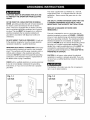
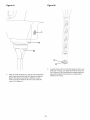
This tool is intended for use on a circuit that has an
electrical receptacle as shown in FIGURE 1. FIGURE 1
shows a 3-wire electrical plug and electrical receptacle
that has a grounding conductor. If a properly grounded
electrical receptacle is not available, an adapter as
shown in FIGURE 2 can be used to temporarily connect
this plug to a 2-contact ungrounded receptacle. The
adapter has a rigid lug extending from it that MUST be
connected to a permanent earth ground, such as a
properly grounded receptacle box. THIS ADAPTER IS
PROHIBITED IN CANADA.
CAUTION: In all cases, make certain the electrical
receptacle in question is properly grounded. If you are
not sure have a certified electrician check the electrical
receptacle.
CHECK with a qualified electrician or service personnel
if you do not completely understand the grounding
instructions, or if you are not sure the tool is properly
grounded.
Fig. 1-1
120 Volt
This Mortiser is for indoor use only. Do not expose to
rain or use in damp locations.
Fig. 1-2
120 Volt
grounding
conductor
grounding
adapter lu
grounding
conductor
0
(_
0
3-prong
electrical
receptacle
3-wire power cord
3-wire power cord
2-prong
electrical
receptacle
SPECIFIC
SAFETY
INSTRUCTIONS
ALWAYS WEAR EYE PROTECTION. Any power tool
can throw debris into the eyes during operations, which
could cause severe and permanent eye damage.
Everyday eyeglasses are NOT safety glasses.
ALWAYS wear Safety Goggles (that comply with ANSI
standard Z87.1) when operating power tools. Safety
Goggles are available at Sears Retails Stores.
Basic precautions should always be followed when
using any power tool. To reduce the risk of injury,
electrical shock or fire, comply with the safety rules
listed below:
.
.
.
.
.
.
.
8.
.
READ and understand the instruction manual
before operating this power tool.
15. USE ONLY DRILL BITS OR CUTTING TOOLS
that are not damaged. Damaged items can cause
malfunctions that lead to injuries.
16. ALWAYS position the hold-down directly over the
workpiece to prevent the workpiece from lifting
during operation. Loss of control of the workpiece
can cause serious injury.
17. TURN THE MACHINE "OFF" AND WAIT FOR
THE DRILL BIT, CUTTING TOOL, OR SANDING
DRUM TO STOP TURNING prior to cleaning the
work area, removing debris, removing or securing
work-piece, or changing the angle of the table. A
moving drill bit or cutting tool can cause serious
injury.
DO NOT OPERATE THIS MACHINE until it is
assembled and installed according to the instructions.
18. PROPERLY SUPPORT LONG OR WIDE work-
OBTAIN ADVICE FROM YOUR SUPERVISOR,
instructor, or another qualified person if you are not
familiar with the operations of this power tool.
19. NEVER PERFORM LAYOUT, ASSEMBLY OR
SET-UP WORK on the table/work area when the
machine is running. Serious injury can result.
DO NOT leave any power tool plugged into the
electrical outlet. Unplug it from the outlet when not
in use and before servicing and cleaning.
pieces, loss of control of the workpiece can cause
severe injury.
TO REDUCE THE RISK OF ELECTRICAL
SHOCK, do not use outdoors. Do not expose to
rain. Store indoors.
20. TURN THE MACHINE "OFF", disconnect the
machine from the power source, and clean the
table/work area before leaving the machine.
REMOVE THE SWITCH KEY to prevent unauthorized use. Someone else might accidentally start the
machine and cause serious injury to themselves.
FOLLOW all electrical and safety codes, including
the National Electric Code (NEC) and the Occupational Safety and Health Regulations (OSHA).
All electrical connections and wiring should be
made by qualified personnel only.
21. REPLACE a damaged cord immediately. DO NOT
use a damaged cord or plug. If the power tool is not
operating properly, or has been damaged, left outdoors or has been in contact with water, return it to
a Sears Service Center.
DO NOT handle the plug or mortiser with wet hands.
CONNECT power tool to a properly grounded outlet
only. See grounding instructions.
SECURE THE MACHINE TO A SUPPORTING
SURFACE. Vibration can cause the machine to
slide, walk, or tip over.
10. NEVER START THE MACHINE with the drill bit or
cutting tool against the workpiece. Loss of control of
the workpiece can cause serious injury.
11. PROPERLY LOCK THE DRILL BIT OR CUTTING
TOOL IN THE UNIT before operating this machine.
12. ADJUST the depth stop to avoid drilling into the table.
13. DO NOT attempt to mortise material that does not
have a flat surface, unless a suitable support is
used.
14. USE ONLY DRILL BITS, CUTTING TOOLS, OR
OTHER ACCESSORIES with shank size recommended in your instruction manual. The wrong size
accessory can cause damage to the machine
and/or serious injury.
22. USE only as described in this manual. USE accessories only recommended by Sears.
23. USE only the key that is provided
by the manufacturer or a duplicate
mechanism is used as an integral
is intended for mandatory removal
the chuck key before the mortiser
with the mortise
of it. An ejection
part of the key. It
or self-ejection of
can be turned on.
24. ADDITIONAL INFORMATION regarding the safe
and proper operation of this product is available
from the National Safety Council, 1121 Spring Lake
Drive, Itasca, IL 60143-3201 in the Accident
Prevention Manual for Industrial Operation and also
in the Safety Data Sheets provided by the NSC.
Please also refer to the American National
Standards Institute ANSI 01.1 Safety Requirements
for Woodworking Machinery and the U.S.
Department of Labor OSHA 1910.213 Regulations.
25. SAVE THESE INSTRUCTIONS.
Refer to them fre-
quently and use them to instruct other users.
AVAILABLE
ACCESSORIES
Sears may recommend other accessories not listed in
this manual,
May be available at your Sears Hardware Department or
see the Sears Power and Hand tool Catalog or visit
WWW.SEARS.COM for the following accessories,
ITEM
STOCK
See your nearest Sears Hardware Department or
Craftsman Power and Hand Tool Catalog for other
accessories.
NUMBER
1/4" Mortising Drill Bit
26411
5/16" Mortising Drill Bit
26412
3/8" Mortising Drill Bit
26413
1/2" Mortising Drill Bit
26414
1/4" Mortising Chisel
26415
5/16" Mortising Chisel
26416
3/8" Mortising Chisel
26417
1/2" Mortising Chisel
26418
Do not use any accessory unless you have completely
read the Instruction Manual for that accessory,
Use only accessories recommended for this mortiser.
Using other accessories may cause serious injury and
cause damage to the mortiser.
UNPACKING
AND CHECKING
CONTENTS
This mortiser will require some amount of assembly.
Three L handle allen wrenches (8mm, 6mm and 5mm)
and one T handle allen wrench (4mm) are provided for
assembly.
Remove all protective materials and coatings from the
parts. The protective coatings can be removed by
spraying WD-40 on a part and wiping it off with a soft
cloth. This may need to be redone several times before
all of the protective coatings are removed completely.
CAUTION: DO NOT use acetone, gasoline or lacquer
thinner to remove any protective coatings.
After cleaning, apply a good quality automotive wax to
any unpainted surfaces. Make sure to buff out the wax
before assembly.
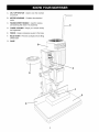
Remove all of the parts from the shipping box and lay
them on a clean work surface. Compare the items to
Figure 3 and verify that all items are accounted for
before discarding the shipping box.
To avoid serious injury, do not attempt to plug in the
power cord and turn "ON" the morfiser if any parts are
missing. The morfiser should only be turned "ON" after
all the parts have been obtained and installed correctly.
The following items and hardware are to be provided in
the shipping box:
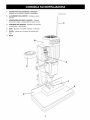
Figure
3
26 25
5
I
24
Ill
30
®
©
27
29 28
1. Mortiser
12. (4) M8 Lock Washers
22. Tool and Chisel Holder
2. Spacer Block
3. Raise / Lower Handle
13. (4) M8 Flat Washers
14. (4) M8 x 30mm Hex Head Screws
23. Hydraulic Cylinder
24. Hold Down
4. Fence Assembly
5.5mm L-Handle Allan Wrench
15. (4) M8 x 80mm Hex Head Screws
16. Base
25. Spring
26. Shoulder Bolt
6.6mm
L-Handle Allen Wrench
17. Micro Adjust Assembly
27. Guide Rod
7. 8mm L-Handle Allen Wrench
18. Lower Ball Stud Fitting
28. 1/2" Mortising Chisel and Bit
8. Chuck Key
9 4mm T-Handle Allen Wrench
19. (2) M4 x 8mm Pan Head Screws
29. 3/8" Mortising Chisel and Bit
20. (2) M4 Flat Washers
30. 5/16" Mortising Chisel and Bit
21. Support Bar
31. 1/4" Mortising Chisel and Bit
10. Long Fence Lock Handle
11. Short Fence Lock Handle
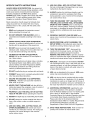
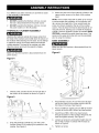
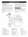
A. ON/ OFF
SWITCH - Used to turn the mortiser
on and off
B.
MOTOR HOUSING - Contains the electrical
motor
C.
RAISE/LOWER HANDLE - Used for raising
and lowering the chisel/bit assembly
D.
CHISEL HOLDER - Keeps your chisels handy
and organized
E.
FENCE - Keeps workpiece square to the base
F. HOLD DOWN - Prevents workpiece from lifting
off the base
G.
BASE
©
A
I
D
F
E
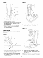
3.
Four different size allen wrenches are provided to assist
in the assembly of the Mortiser.
1.
DO NOT assemble the Mortiser until you are sure
the tool is disconnected from the power source.
2.
DO NOT assemble the Mortiser until you are sure
the power switch is in the off position.
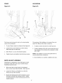
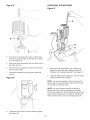
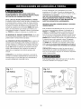
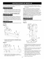
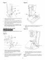
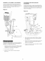
HYDRAULIC
CYLINDER
Attach the other end of the hydraulic cylinder to the
upper junction screw on the back of the mortiser
head.
NOTE: If the mortiser head will not slide up far enough
to accommodate the installation of the hydraulic cylinder, remove the single M6 x 10ram socket head cap
screw (not shown) located at the top of the mortiser
column. This will allow the head to slide beyond its normal path of travel, allowing you to install the hydraulic
cylinder. Once the hydraulic cylinder is installed, MAKE
CERTAIN to reinstall the socket head cap screw. This
serves as the upper limit stop and must be reinstalled
prior to using the mortiser.
ASSEMBLY
Attaching the hydraulic cylinder first makes certain that
the head of the mortiser cannot slide down the column of
the mortiser while attaching it to the base. Do not attempt
to attach the column to the base without the hydraulic
cylinder attached. The head of the mortiser may slide
down the column and crush the operator's fingers.
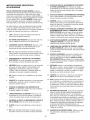
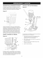
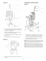
BASE ASSEMBLY
Make sure that the machine is disconnected from the
Figure 6
Make sure that the machine is disconnected from the
power source.
power source.
Figure
4
A
C
B
B
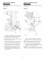
1.
Thread Lower Junction Screw (A) into hole (B) of
the column of the mortiser as shown in Figure 4.
Figure 5
.
C
D
.
.
.
2.
Snap the Hydraulic Cylinder (C) over the Lower
Junction Screw (D) by applying firm pressure to the
cylinder. See Figure 5.
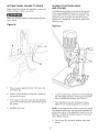
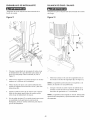
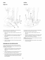
5.
10
Place Mortiser column (A) over the base (B) aligning the four holes in the mortiser column with the
four holes in the base. See Figure 6.
Place one M8 lock washer and one M8 flat washer
on each of the four M8 x 30ram hex head screws.
insert three of M8 x 30ram hex head screws
through the bottom of the mortiser, thread into the
base and tighten securely. See Figure 6.
Loosen set screw (C) and position depth stop rod
(D) so that it comes in contact with the base as
shown in Figure 6.
Tighten set screw.
Figure 7
Figure 9
G
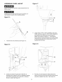
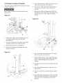
Detach Hydraulic Cylinder (E) from lower junction
screw See Figure 7.
,
Unscrew lower junction screw (F).
,
8.
Insert final M8 x 30mm hex head screw (G) through
the bottom of the mortiser, thread into the base,
and tighten securely.
3.
Screw in lower junction screw and reattach the
hydraulic cylinder as explained in HYDRAULIC
CYLINDER ASSEMBLY.
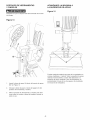
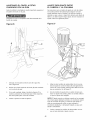
,
Insert fence glide shaft (G) through hole (H) in
column of the mortiser. See Figure 9.
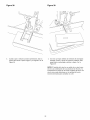
Figure 10
FENCE
ASSEMBLY
Make sure that the machine is disconnected from the
power source
Figure
8
\
/
E
©
F
,
Insert Guide Rod (A) through hole in Hold Down (B)
and tighten set screw (C) using supplied 4mm T
Handle allen wrench. See Figure 8.
,
Insert Guide Rod into hole (D) of Fence Assembly
(E) and tighten set screw (F) using supplied 4mm
T Handle allen wrench.
4.
Thread Short Fence Lock Handle (I) into the
column of the mortiser. Tighten to secure fence.
See Figure 10.
NOTE: Fence Lock Handle is spring loaded and can be
repositioned by pulling out on the handle and rotating it.
11
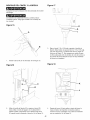
MICRO ADJUST
ASSEMBLY
RAiSiNG
/ LOWERING
HANDLE
Make sure that the machine is disconnected from the
Make sure that the machine is disconnected from the
power source.
power source.
Figure 11
Figure
A
12
B
F
E
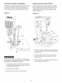
,
Fit the Micro Adjust Assembly (A) over the Fence
Glide Shaft (B) until the Support Plate (C) is flush
up against the Column (D). See Figure 11.
,
Align the two holes in the support plate with the two
holes in the mortiser column.
,
Fasten support plate to the column using two M4 x
8mm pan head screws and two M4 flat washers.
,
Tighten Lock Knob (E) so that the Micro Adjust
Assembly fits tightly on the Fence Glide Shaft.
,
Rotate Adjust Knob (F) clockwise to move the
Fence Assembly towards the Mortiser column.
Turn counter clockwise to move the fence away
from the Mortiser.
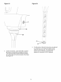
1.
Line up the notches in the hub of the handle (A)
with the slots in the gear shaft (B). See Figure 12.
NOTE: The handle may be attached to either the left
side or right side, depending on your preference.
2.
Place spring (C) over the shoulder bolt (D) and
insert through the hub of the handle. Tighten using
supplied L -Handle 8mm allen wrench.
NOTE: The handle is spring loaded. You can reposition
it by pulling it out and repositioning it on the gear shaft.
12
TOOL AND CHISEL
HOLDER
FASTENING
MACHINE TO
SUPPORTING
SURFACE
Make sure that the machine is disconnected from the
Figure 14
power source.
Figure
13
®
/
C
,
,
,
If during operation there is any tendency for the morfiser
to tip over, slide, or walk on the supporting surface, the
base must be secured to the supporting surface with
fasteners (not supplied), through the two holes (A)
located in the mortiser base.
Insert the support bar (A) into the support bracket
(B). See Figure 13.
Place the support bar through the hole (C) of the
tool and chisel holder.
Use tool and chisel holder to store all chisels and
chuck keys when not in use.
13
ASSEMBLING
CHISEL
AND BIT
Figure
17
Make sure that the machine is disconnected from the
power source.
\
\
\
\
\
\
\
\
Chisels are very sharp and can cause a serious cut.
Take extreme caution when handling chisels.
Figure 15
G
I
A
B
,
/
1.
Insert bit (A) into chisel (B). See Figure 15.
Lower chisel 1/16" to 3/16" and tighten set screw.
There must be a space of 1/16" to 3/16" clearance
(G) between the bushing (H) and shoulder of
chisel (I) as shown in Figure 17. This assures
having proper clearance between the cutting edges
of the bit and points of the chisel after the bit is
inserted into the chuck.
Figure 18
Figure 16
,f
[
/
K
,
Loosen set screw (C) and push chisel (D) up
through hole in head (E) as far as possible, making
sure that the opening in the chisel (F) is facing to
the left or right. See Figure 16.
,
14
Push bit (J) up through the chisel and into the
chuck (K) as far as it will go and lock bit into chuck
using the supplied chuck key. See Figure 18.
Figure
19
Figure 20
M
J
J
,
,
The flat portion of the bit (O) should now be adjusted
to a minimum of 1/16" below the bottom of the
chisel (P). See Figure 20. For certain types of
wood it may be necessary to increase this
distance to a maximum of 3/16" clearance.
Loosen set screw (L), push chisel (M) up against
the bottom of bushing (N) and tighten set screw.
This should provide the proper distance between
the cutting edges of the bit and points of the chisel
See Figure 19.
15
ON-OFF
SWITCH
DEPTH
The switch is located on the side of the motor, To turn
the machine on flip the switch up to the "ON" position,
To turn the machine off, move the switch down to the
"OFF" position.
Figure
Figure
STOP ROD
23
21
B
When the tool is not in use, the switch should be locked
in the "OFF" position to prevent unauthorized use. This
can be done by grasping the switch toggle (A) and
pulling it out of the switch. With the switch toggle
removed, the switch will not operate. Should the toggle
be removed while the machine is running, the switch
can be turned off once, but cannot be restarted without
inserting the switch toggle. See Figure 21.
RAISING
Figure
AND LOWERING
D
The depth stop rod is provided to limit the depth of the
chisel. See Figure 23.
THE HEAD
22
B
The head is raised and lowered by using the lever. For
maximum leverage during the mortising operation, the
lever can be repositioned by pulling out the hub (A) of
the lever assembly and repositioning hub on the pinion
shaft (B). See figure 22.
16
1.
To adjust the depth stop rod (A), loosen set screw
(B) using provided 4mm T handle allen wrench.
2.
Lower head until the chisel(C) is at the desired
depth.
3.
Lower depth stop rod until it contacts the base (D).
4.
Tighten set screw.
FENCE
HOLDDOWN
Figure 24
Figure 25
c
E
///
ii
/
B
I/i
D
C
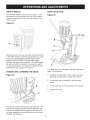
The Fence can be moved in and out to accommodate
various size workpieces.
The purpose of the holddown is to prevent the workpiece from lifting as the chisel is raised up.
1.
To move Fence, loosen Lock Knob (A) See Figure 24.
1.
To adjust, loosen set screw (A). See Figure 25.
2.
Loosen Fence Lock Handle (C) until the Fence
Glide Shaft (B) can slide freely.
2.
3.
Slide Fence in or out to the desired location.
Position Holddown (B) until it just touches the top of
the workpiece (C) and allows the workpiece to slide
left or right.
4.
Tighten Fence Lock Handle to lock the fence in place.
NOTE: The holddown can be turned upside down to
accommodate thicker workpieces.
3. Once Holddown is in position, retighten set screw.
MICRO ADJUST
ASSEMBLY
Sometimes it is necessary to move the fence in small
increments. When this is the case, the Micro Adjust
Assembly should be used.
1.
Make sure that the Lock Knob (A) is tightened
down on the Fence Glide Shaft (B). See Figure 24.
2.
Loosen the Fence Lock Handle (C) so that the
Fence (D) may slide smoothly.
,
Rotate the Adjustment Knob (E) clockwise to move
the fence in towards the mortiser column. Rotate
counterclockwise to move the fence away from the
mortiser column.
17
SETTING
CHISEL
SQUARE
SLIDING FIT BETWEEN
AND COLUMN
TO FENCE
Before using the mortiser, it is important to make sure
that the chisel is square to the fence.
A dovetail gib is provided on the rear of the head to
insure a good sliding fit between the head and the
column when the head is raised and lowered. This
should be set at the factory and should not need
adjustment. If adjustment is necessary, perform the
following steps.
Make sure that the mortiser is disconnected from the
power source.
Figure
HEAD
26
Figure
27
1
\
A
C
©
,
Place a square against the face of the fence (A).
See Figure 26.
,
Check to see if left side of chisel (B) is square to
the face of the fence.
,
If not square, loosen set screw (C) and reposition
chisel until the left side of the chisel is flat against
the square.
4.
,
2.
Retighten set screw.
Loosen 2 allen head screws (A) in the dovetail gib
(B) only slightly (less than 1/8 turn) using provided
6mm L-Handle Allen Wrench. See Figure 27.
Turn adjusting screws (C) clockwise to make a
tighter fit, turn counterclockwise for a looser fit.
NOTE: Correct adjustment is when a good snug sliding
fit is obtained without any side movement between the
gib and the column. This adjustment should not be too
tight that it restricts the sliding movement or too loose
that it affects accuracy.
3.
18
Once proper fit is achieved, retighten allen head
screws.
ATTACHING
COLUMN
EXTENSION
The column can be extended for the purpose of mortising taller workpieces
Make certain the machine is disconnected from the
,
Snap off the hydraulic cylinder (G) and remove the
lower junction screw (H). See Figure 29.
,
Remove the 4 M8 x 30mm Hex Head screws (I)
and remove the mortiser column (J) from the
base (K).
,
power source.
Remove the 4 M8 Lock Washers and 4 M8 Flat
Washers from the 4 M8 x 30mm Hex Head screws
and put them on the 4 M8 x 80mm Hex Head
Screws.
Figure 28
Figure
F
30
C
,
,
,
4.
Remove the 2 M4 x 8mm Pan Head Screws (A)
that fasten the MJcroAdjust Assembly (B).
See Figure 28.
Loosen Lock Knob (C) and remove micro adjust
assembly from the Fence Glide Shaft (D).
Remove Short Fence Lock Handle (E).
Slide Fence Glide Shaft completely out of the
mortiser column (F).
Figure
29
,
,
Line up the holes in the spacer block (L) with the
holes in the base. See Figure 30.
Place mortiser column over the spacer block and
fasten to base using the 4 M8 x 80ram Hex Head
Screws, 4 M8 Lock Washers and 4 M8 Flat
Washers.
10. Reinstall lower junction screw and attach hydraulic
cylinder.
11. Slide Fence Glide Assembly into the hole in the
Spacer Block.
12. Thread Long Fence Lock Handle (M) into spacer
block.
13. Place Micro Adjust Assembly over the Fence Glide
Shaft and fasten to the mortiser column using the
2 M4 x 8mm Pan Head Screws and 2 M4 Flat
Washers.
K
19
ROTATING
COLUMN
180 DEGREES
USING AUXILIARY
WOOD
FENCE
Sometimes a workpiece may be too large to fit between
the base and the chisel. When this is the case, you
can rotate the column of the mortiser 180 degrees, as
shown, and perform the work off of a bench or floor.
When mortising an extra high workpiece, an auxiliary
fence can be fastened to the fence with wood screws
(not provided) through the holes in the fence. This
provides additional support for the workpiece during
mortising operation.
Figure 31
Figure 32
A
,
B
,
When rotating column 180 Degrees, you must fasten
the machine to a supporting surface. See FASTENING
MACHINE TO SUPPORTING SURFACE.
1.
To rotate the column, remove the four M8 x 30mm
Hex Head Screws that bolt the mortiser column (A)
to the base (B). See Figure 31.
2.
Rotate Column 180 degrees.
3.
Replace four M8 x 30mm Hex Head Screws.
,
20
To attach a wooden auxiliary fence, place auxiliary
fence (A) up against the face of the main fence (B).
See Figure 32.
Fasten auxiliary fence to main fence through the
holes (C) in the main fence using wood screws
(not provided).
Place workpiece (D) up against auxiliary fence and
secure using the holddown (E).
USING
SACRiFiCiAL
BOARD
USING
When performing a through mortise, it is a good practice to use a sacrificial board to prevent any chipout at
the bottom of the mortise.
Figure
BITS WITH EXTRA
LONG SHANKS
When using bits with extra long shanks, it will be necessary to remove the extension.
33
Make certain that the mortiser is disconnected from the
power source.
1.
Remove the mortising bit.
Figure 34
E
A
D
A
@
C
,
To attach a sacrificial board, place sacrificial board
(A) against the face of the fence (B). See Figure 33.
,
Attach sacrificial board to fence using wood screws
(not provided) though the holes of the fence (C).
,
4.
Place workpiece (D) on top of sacrificial board and
up against the fence.
Fasten workpiece using the holddown (E).
,
Insert a flat head screwdriver
into the center hole
(A) of the motor end cap. See Figure 34.
,
21
Insert the chuck key (B) into the chuck (C) and
rotate screwdriver counterclockwise until the chuck
comes loose from the extension.
OPERATING
Figure 35
Figure
THE MORTISER
37
®
.
.
.
7.
To remove the extension (D), place a 16mm open
end wrench (not provided) on the flats of the extension. See Figure 35.
Insert a flat head screwdriver
the motor end cap.
into the center hole of
Turn the wrench clockwise to loosen the extension
from the motor shaft.
1.
Make sure that the workpiece (A) is held firmly
against the fence (B) when cutting and that the
holddown (C) is properly adjusted. See Figure 37.
2.
Using the Raise/Lower handle (D), lower the chisel
until it penetrates the workpiece.
Unscrew the extension from the motor shaft and
remove.
Figure
36
NOTE: The rate of penetration of the chisel must be
fast enough to prevent burning at the tip of the bit, but
not too fast as to stall the motor.
o
.
o
NOTE: You may encounter smoke from the bit or
material once the chisel has engaged the material.
The smoke created is a natural operating occurrence in
hollow chisel mortising and is caused by material chip
friction and the resins in the stock being burned off.
o
Thread the chuck onto the motor shaft and tighten.
See Figure 36.
22
Figure 38
,
Figure 39
When making next penetration, leave a gap
between the first and second holes. See Figure 38.
4.
Once the desired length of the mortise is achieved,
go back and chisel out the remaining gaps. This
will ensure a smooth, clean mortise. See Figure 39.
NOTE: Bluing of the chisel is not indicative of a dull
chisel, but a combination of friction and resin buildup
on the cutting faces of the chisel. A dull chisel can be
detected by the amount of excess force required to
complete a cut.
23
Repairstothis powertoolshouldbe performed
by
trainedpersonnel
only.ContactyournearestSears
ServiceCenterforauthorized
service.Unauthorized
repairsor replacement
withnon-factory
partscould
causeseriousinjuryto theoperatoranddamageto
yourmachine.
To clean and maintain the unpainted cast iron surfaces:
• Apply a heavy coat of WD-40 onto the unpainted cast
iron surface.
Use a fine steel wool pad to buff the unpainted cast
iron. Make sure to buff in a "front to rear" direction
only. A side-to-side buffing motion will show in the
finely ground cast iron as a flaw, defect or scratches.
Topreventinjurytoyourselfor damageto themachine,
turntheswitchtothe"OFF"positionandunplugthe
powercordfromthe electricalreceptacle
beforemaking
anyadjustments.
Reapply WD-40 and buff the unpainted cast iron
surfaces until the stain is removed. Make sure you
use the same front-to-rear buffing direction to avoid
scratching or marring the cast iron surface.
TheMortiserwilloperatebestif it is keptin proper
operatingcondition.Keepunitadjustedas described
in
OPERATIONS
ANDADJUSTMENTS.
• After all stains and/or rust have been removed,
clean all oil and dirt from the table saw using a soft
cloth or rag.
• Turnthe powerswitch"OFF"andunplugthepower
cordfromitspowersource.
• Donotallowgumandpitchto accumulate
oncutting
tool.
Lastly, you need to apply a good automotive paste
wax to all unpainted cast iron surfaces. This will help
to protect the saw from rusting from further contact
with moisture or oily hands.
• Donotallowchipstoaccumulate
onor aroundthe
machine.
• Keepchiselsandbitssharp.Keepinga sparesetof
chiselsandbitsonhandis recommended.
Replacementchiselsandbitsareavailableat Sears.
CAUTION:DONOTUSEFLAMMABLEMATERIALS
to cleanthismachine.Acleandryragor brushis all
thatis neededto removedustanddebrisbuildup.
PROTECTING
FROM RUST
LUBRICATION
The Mortiser has sealed lubricated bearings in the
motor housing that do not require any additional
lubrication from the operator.
• Fence guide and elevation screws should be cleaned
of debris and greased as needed.
CAST IRON TABLE
• Occasionally apply a few drops of light machine oil to
gibs to keep tables free in relation to base.
MAKE CERTAIN to turn the power "OFF" and unplug
the power cord from its power source.
The environment and frequency of human contact can
have a very detrimental impact on unpainted cast iron
surfaces. Moisture, humidity and oils (from human
hands!) can cause the unpainted cast iron surfaces to
mar or rust, so it is important to conduct routine maintenance to keep your mortiser looking new. Cleaning
and waxing the cast iron surfaces on a regular maintenance schedule is recommended as follows:
24
TOPREVENT
INJURYTOYOURSELF
or damagetothe mortiser,turntheswitchtothe OFFpositionandunplugthe
powercordfromthe electricalreceptacle
beforemakinganyadjustments.
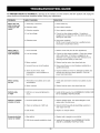
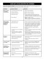
PROBLEM
LIKELY CAUSE(S)
SOLUTION
Motor does not
start or does not
come up to full
speed
1. Switch key is removed.
1. Insert switch key.
2. Defective switch
2. Have switch replaced.
3. Defective capacitor
3. Have capacitor replaced.
4. Low line voltage
4. Correct low line voltage condition. If machine is
plugged into an extension cord, disconnect and plug
directly into wall outlet.
5. Defective motor
5. Have motor replaced.
NOTE: 3 and 4 must be done by a qualified service
technician; Consult Sears service.
Motor stalls or
circuit breakers
open frequently
1. Circuit overload
1,
Reduce circuit load (turn off other appliances).
2. Correct low line voltage condition. Check line voltage
with a multi-meter. If mortiser is plugged into an
extension cord, unplug mortiser from extension cord
and plug mortiser directly to wall outlet.
2. Low line voltage
3. Motor overload
3,
4. Incorrect fuses on circuit breakers
Reduce load on motor, slow down feed rate.
4. Have correct fuses on circuit breakers installed by a
qualified electrician.
5. Short circuit in motor; loose
connections or worn insulation on
lead wires.
5,
Inspect terminals in motor for damaged insulation and
shorted wires and have them replaced. Check all
power lead connections.
1. Restricted air circulation due to dust
accumulation.
1. Clean dust and restore normal air circulation around
motor.
2. Motor overload
2. Reduce load on motor, slow down feed rate.
Drill bit stalls
or slips
1. Drill bit is not securely tightened in
chuck.
1. Install drill bit properly. See ASSEMBLING
BIT in ASSEMBLY INSTRUCTIONS.
Drill bit or material
smokes or burns
1. Incorrect spindle speed.
1. Reduce spindle speed. See speed diagram on the
under side of the belt cover.
2. Chips not exiting out of drill hole.
2. Retract drill bit frequently during drilling operation to
clear chips from hole.
3. Dull drill bit.
3. Replace or sharpen drill bit.
1. Bent drill bit.
1. Replace with a straight or new drill bit.
2. Drill bit not properly installed in chuck.
2. Install drill bit properly. See ASSEMBLING
AND BIT in ASSEMBLY INSTRUCTIONS.
Motor running
too hot
Excessive drill bit
runout or wobble
25
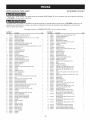
CHISEL AND
CHISEL
HOLLOWCHISELMORTISER
When servicing, use only CRAFTSMAN
product damage.
MODELNO.351.219071
replacement parts. Use of any other parts may create a HAZARD or cause
Any attempt to repair or replace electrical parts on this Mortiser may create a HAZARD unless repair is done by a
qualified service technician. Repair service is available at your nearest Sears Service Center.
Always order by PART NUMBER, not by key number.
KEY
NO.
PART
NO.
DESCRmPTION
KEY
NO.
QTY.
PART
NO.
DESCRmPTmON
QTY.
1
1A
1B
1C
2
3
4
5
8
7
8
9
10
OR93300
OR93301
OR93354
OR93353
OR93781
OR93302
OR93783
OR93383
OR93303
OR93304
OR93305
OR93782
OR93306
MOTOR MAIN ASSY (INCL, 1A,1B,1C,2,3,4,5,8,7,8,9)
MOTOR ASSY. INCL: 1/2HP 120V 6A 1720RPM
POWER CORD
STRAIN RELIEF
CRAFTSMAN LABEL
SWITCH BOX COVER
SPECIFICATION LABEL
2.9 X 12MM SELF TAP PAN HD SCREW
CAPACITOR 18UF
SWITCH
SWITCH KEY
NAMEPLATE
ADAPTER
1
1
1
1
1
1
1
6
1
1
1
1
1
55
58
57
58
59
60
81
82
83
84
85
88
87
OR93314
OR90507
OR93330
OR93331
OR93332
OR93333
OR93372
STD852008
OR93334
OR93370
STD851004
OR90346
OR93335
11
11A
OR93307
OR93352
CHUCK
CHUCK KEY
1
1
88
89
STD851008
OR93336
12
13
OR93308
OR93309
DEPTH STOP ROD
MOTOR SPACER
1
1
70
71
OR93337
OR93338
HINGE
M5X 8MM PAN HD SCREW
T-HANDLE WRENCH
CHISEL HOLDER
SUPPORT BAR
SUPPORT BRACKET
M6 X 12MM HEX SOC HD SCREW
M6 LOCKWASHER
COLUMN
M6 NYLOK NUT
M4 FLAT WASHER
M4 X 8MM PAN HD SCREW
SUPPORT PLATE
M6 FLAT WASHER
ADJUST KNOB
LOCK KNOB
ADJUST BRACKET
14
15
OR93376
OR93310
M6 X 30MM SPRING PIN
GEAR SHAFT JOINT
1
1
72
73
STD835030
STD852008
M8 X 30MM HEX HD SCREW
M8 LOCKWASHER
4
4
18
17
OR93311
OR93312
PLASTIC WASHER
LOCK KNOB
1
1
74
75
STD851008
OR93339
M8 FLAT WASHER
4
18
19
OR93313
OR90507
SPACER
M5 X 8MM PAN HD SCREW
1
2
78
77
OR93340
STD851006
HANDLE ASSEMBLY (SHORT)
BASE
M6 FLAT WASHER
1
1
2
20
21
OR93314
OR93315
HINGE
COVER
1
1
78
79
STD852008
OR93374
M6 LOCKWASHER
M6 X 20MM HEX SOC HD SCREW
2
2
22
23
OR93311
STD840810
PLASTIC WASHER
M6 HEX NUT
1
1
80
81
OR93341
OR93342
24
25
OR93316
OR93370
LOCK PLATE
M6 NYLOK NUT
1
1
82
83
OR93343
OR93378
26
27
OR91821
OR93317
M8X20MM
BUSHING
1
1
84
85
OR93344
OR93378
28
29
OR93377
OR93318
M6 X 45MM HEX SOC HD SCREW
HEAD CASTING
4
1
88
87
OR93345
OR93346
FENCE GLIDE PAD
FENCE GLIDE ASSY
FENCE
M8 X 10MM HEX SOC SET SCREW
HOLD DOWN
M8 X 10MM HEX SOC SET SCREW
GUIDE ROD
STABILIZER
2
1
1
1
1
1
1
1
30
30A
OR93784
OR93369
WARNING LABEL
3MM DRIVE RIVET
1
88
89
OR93347
OR93348
BALL STUD FITTING
JUNCTION SCREW
2
2
31
32
OR93380
OR93379
M8 X 15MM HEX SOC SET SCREW
M8 X 10MM TRUSS HD SCREW
1
2
90
91
STD840810
OR93373
M6 HEX NUT
M6 X 16MM HEX SOC HD SCREW
2
2
33
34
OR93319
OR93381
COLUMN GUIDE GIB
M8 X 20MM HEX SOC HD SCREW
1
2
92
93
OR93349
OR93371
RACK GEAR
M6 x 10MM HEX SOC HD SCREW
1
1
35
36
37
38
39
40
OR93320
OR93321
OR93323
OR93322
OR93376
OR93310
GEAR
COLLAR
M5 X 5MM HEX SOC SET SCREW
GEAR SHAFT
M6 X 30MM SPRING PIN
GEAR SHAFT JOINT
1
1
1
1
1
1
94
95
96
97
OR93382
OR93350
OR93351
OR93355
M8 X 90MM HEX HD SCREW
SPACER BLOCK
4
1
HANDLE ASSEMBLY (LONG)
CHISELAND DRILL BITASSEMBLY KIT
1
(INCL, 98, 99, 100, 101) (NOT SHOWN)
1
98
OR93356
41
42
OR93806
OR93325
HANDLE ASSEMBLY
SPRING
1
1
99
100
OR93359
OR93382
1/4" CHISEL AND DRILL BIT ASSEMBLY (NOT SHOWN)
5/18" CHISEL AND DRILL BIT ASSEMBLY (NOT SHOWN)
1
1
43
47
OR93326
OR93329
SHOULDER BOLT
KEY
1
1
101
102
OR93385
OR91728
3/8" CHISEL AND DRILL BIT ASSEMBLY (NOT SHOWN)
1/2" CHISEL AND DRILL BIT ASSEMBLY (NOT SHOWN)
1
1
48
49
OR93312
OR93311
LOCK KNOB
PLASTIC WASHER
1
1
103
104
OR90806
OR90292
50
51
52
53
54
OR93311
STD840810
OR93370
OR93316
OR93315
PLASTIC WASHER
M6 HEX NUT
M6 NYLOK NUT
LOCK PLATE
COVER
1
1
1
1
1
106
OR93780
5MM HEX WRENCH (NOT SHOWN)
6MM HEX WRENCH (NOT SHOWN)
8MM HEX WRENCH (NOT SHOWN)
INSTRUCTION MANUAL (NOT SHOWN)
1
1
1
1
HEX SOC SET SCREW
26
1
2
1
1
1
1
2
2
1
1
2
2
1
2
1
1
1
HOLLOWCHISELMORTISER
MODELNO.351.219071
5
IC -/
19 (2)J_
(2)
20-/
33
25
27 _
28 (4)
52
94 (4)
95
96
59
60
62
61 (2)-_
56
(2)
63
68 (2)
66
65 (2)\
"_
_69
93\
87_
88
(2) /
89
_@
_
91
67
(2)/
90 (2)
I
83
80 (2)_
27
28
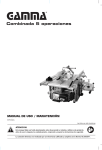
_nual de Instrucciones
®
FITAJADO
Cl CEL U C
E
No. de Modelo
351.219071
C
US
f
PRECAUCION:
PARA SU SEGURIDAD
PERSONAL:
Lea y obedezca todas las
Instrucciones
de Seguridad y
Funcionamiento
antes de hacer
uso de la Mortajadora.
Linea de Ayudaal Cliente
1-800-266-9079
Sirvase tenet listo su
No, de Modelo y No, de Serie
Sears,
Roebuck
and Co., Hoffman
Estates,
No. de Pieza OR93780
VER. 9.08
29
IL 60179 U.S.A.
SECCl6N
P._GINA
Garantia ..............................................................................................................................................................................................
30
Especificaciones
30
Instrucciones
del producto ........................................................................................................................................................
de seguridad
..............................................................................................................................................................
31
Directtices para las e×tensiones el6ctricas ....................................................................................................................................
Instrucciones
de conexi6n a tierra ..................................................................................................................................................
32
33
Instrucciones
34
Accesorios
Contenido
Conozca
de seguridad
y aditamentos
especfficas
.........................................................................................................................................
................................................................................................................................................................
35
de la caja .........................................................................................................................................................................
36
su mortajadora
Instrucciones
..................................................................................................................................................................
37
de montaje .................................................................................................................................................................
38
Operaciones y ajuste ........................................................................................................................................................................
Mantenimiento
...................................................................................................................................................................................
44
52
Guia de Iocalizaci6n
53
Listado
de averias .......................................................................................................................................................
de piezas ..............................................................................................................................................................................
Informaci6n
de servicio
...............................................................................................................................................
GARANTIA COMPLETA
DE UN A_lO PARA HERRAMIENTA
54
Contraportada
CRAFTSMAN
Siesta herramienta Craftsman fallara por causa de defectos en el material o en la mano de obra en un lapso de un
aSo a partir de la fecha de compra, LLAME al 1-800-4-MY-HOME® PARA SOLICITAR LA REPARACION
GRATUITA DEL PRODUCTO (o su reemplazo si no se puede reparar la unidad).
Si esta herramienta se usa alguna vez para fines comerciales o de alquiler, esta garantia es valida 0nicamente por
90 dias a partir de la fecha de compra.
Esta garantia aplica unicamente mientras la herramienta esta en los Estados Unidos.
Esta garantia le otorga derechos legales especificos y tambien puede usted tenor otros derechos que varien de
estado a estado.
Sears, Roebuck and Co., Hoffman Estates, IL 60179
Tipo de motor:
Inducci6n
Altura del bloque de elevaci6n
2-1/4 pulg.
HP de servicio continuo
1/2 hp
Amperios
Voltios
6
120
Guia compatible con
elbloque de elevaci6n
Si
Hertzios
60
RPM
1725
Tipo de mandrino
Llave
Capacidad maxima del mandrino
3/8 pulg
Dimensiones
de cincel:
Microajuste compatible
el bloque de elevaci6n
3/8 x 3/8 pulg.
1/2 x 1/2 pulg.
Posici6n de la agarradera
Izquierda o derecha,
intercambiable
Bloque de elevaci6n incluido
5 pulg.
8 pulg.
Distancia del centro del
1/4 x 1/4 pulg.
Si
Si
Si
Golpe de carrera maximo
Distancia del fondo del
cabezal a la base
5/16 x 5/16 pulg.
Microajuste
Portador de broca
con
cincel a la guia
3-1/8 pulg.
Bajo el ret6n, posici6n baja
7/8 a 3-1/4 pulg.
Bajo el ret6n, posici6n elevada
1-7/8 a 4-1/4 pulg.
Dimensiones
Dimensiones
14-1/2 x 2-1/2 pulg.
de la gu[a
de la base
Dimensiones totales:
Si
13-3/4 x 8-3/4 pulg.
Alto:
31 pulg.
Ancho:
14-1/2 pulg.
Profundidad:
16-1/2 pulg.
68 libras
Peso:
3O
INSTRUCCIONES
DE SEGURIDAD
GENERALES
El uso de una Mortajadora puede ser peligroso si se hace
caso omiso de la seguridad y el sentido comen. El operario
debe estar familiarizado con el funcionamiento de esta herramienta. NO OPERE esta Mortajadora si no entiende plenamente las limitaciones de esta herramienta. NO MODIFIQUE
este Mortajadora de ninguna manera. REOUERDE: Su
seguridad personal es su responsabilidad.
ANTES DE HACER USO
DE LA MORTAJADORA
Parte del polvo que se crea usando las herramientas
el6ctricas contiene productos quimicos que el estado de
California reconoce como causantes de cancer, defectos
de nacimiento, o da_os en el sistema reproductivo.
Algunos ejemplos de estos productos quimicos son:
• El plomo de pinturas con
El riesgo de estas exposiciones varia, dependiendo de
cuantas veces se realiza este tipo de trabajo. Para
reducir tu exposici6n a estos productos quimicos, trabaje
en un Area bien ventilada, y trabaje con el equipo
aprobado de seguridad, tal como mascaras dise_adas
para el polvo.
12. DESENCHUFE LA HERRAMIENTA DEL TOMACORRIENTES SIEMPRE que vaya a realizar cualquier
ajuste, recambio de piezas o Ilevar a cabo cualquier
tarea de mantenimiento.
13. MANTENGA TODOS LOS PROTECTORES EN SUS
SITIOS Y EN BUENAS CONDICIONES DE TRABAJO.
LEA el Manual de Instrucciones cabalmente. APRENDA
como usar la herramienta para su aplicaci6n propuesta.
CONECTE TODAS LAS HERRAMIENTAS
14. EVITE LOS ARRANQUES ACCIDENTALES. AsegtJrese
de que el interruptor de energia se encuentre en la posici6n de "OFF" (apagado) antes de enchufar el cord6n de
potencia y causar daSo a la herramienta.
A TIERRA.
Si la herramienta viene equipada con un enchufe de tres
machos, se le debe enchufar en un tomacorrientes de
tres contactos. El tercer macho se utiliza para conectar la
herramienta a tierra y ofrecer protecci6n contra los
choques el6ctricos accidentales. NO QUITE el tercer
macho. Ver Instrucciones de conexi6n a tierra.
4,
UTILICE LA VESTIMENTA CORRECTA. NO utilice ropa
holgada, guantes, corbatas ni articulos de joyeria. Estos
articulos pueden quedar atrapados en la maquina
durante las operaciones y arrastrar al operario hacia las
piezas en movimiento. El usuario debe Ilevar una cubierta protectiva sobre su cabello, si tiene cabello largo, para
protegerlo contra el contacto con cualquier pieza en
movimiento.
11. UTILICE PROTECClON AUDITIVA SlEMPRE. El algod6n por si solo no constituye un dispositivo de protecci6n
aceptable. El equipo auditivo debe cumplir con las
normativas $3.19 de ANSI.
• El arsenico y el cromo de la madera de construcci6n
quimicamente tratada
3,
9,
base de plomo
• El Silic6n cristalino de ladrillos, cemento, y de otros
productos de alba_ileria
2,
NO FUERCE LA HERRAMIENTA para realizar una
operaci6n para la que no fue diseSada. Realizara un
trabajo mas seguro y de mayor calidad s61o efectuando
aquellas operaciones para las que fue diseSada.
10. UTILICE PROTECCI(SN OCULAR SlEMPRE. Cualquier
herramienta mecanica puede expulsar escombros hacia
los ojos durante las operaciones, causando daSo ocular
grave y permanente. Los anteojos de uso cotidiano NO
son gafas de seguridad. Utilice gafas de seguridad
SlEMPRE (que cumplan con la normativa Z87.1 de
ANSI) cuando vaya a operar herramientas mecanicas.
Las gafas de seguridad estan disponibles en las tiendas
de Ventas al Detal de Sears.
Lea y obedezca todas las instrucciones de Seguridad y
Operaci6n antes de operar la Mortajadora para evitar heridas
graves y daSo a la herramienta.
1,
8,
15. RETIRE TODAS LAS HERRAMIENTAS DE MANTENIMIENTO de la zona inmediata antes de ENCENDER la
herramienta.
16. S(SLO UTILICE LOS ACCESORIOS
EVITE UN ENTORNO DE TRABAJO PELIGROSO. NO
utilice las herramientas el6ctricas en entornos htJmedos
ni las exponga a la Iluvia.
5,
NO utilice herramientas el6ctricas en la presencia de
liquidos o gases inflamables.
6.
Mantenga la zona de trabajo limpia, bien iluminada y
organizada EN TODO MOMENTO. NO trabaje en un
entorno con superficies de piso resbalosas debido a los
escombros, grasas y cera.
7.
MANTENGA ALEJADOS A LOS VISITANTES Y NINOS.
RECOMENDADOS.
El uso de accesorios incorrectos o indebidos puede
resultar en heridas graves al operario y causar daSo a la
herramienta. Si tiene dudas, consulte el manual de
instrucciones que viene con ese accesorio en particular.
17. NUNCA DEJE UNA M/_,QUlNA EN FUNClONAMIENTO
SIN ATENDER. Mueve el interruptor de energia a la
posici6n de "OFF" (apagado). NO se aleje de la maquina
hasta que se haya detenido por completo.
18. NO SE PARE SOBRE LA HERRAMIENTA. Esto podria
resultar en heridas graves si la herramienta se vuelca o
si usted hace contacto accidental con la herramienta.
NO permita que haya gente en la zona inmediata de
trabajo, sobre todo cuando la herramienta el6ctrica se
encuentre en funcionamiento.
31
19. NO almacene nada sobre o cerca de la herramienta
28. UTILICE UNA EXTENSIC)N ELI_CTRICA EN BUEN
donde alguien pueda intentar pararse sobre la herramienta para alcanzarlo.
ESTADO. Cuando vaya a hacer uso de una extensi6n
el_ctrica, asegtJrese de utilizar una que sea Io suficientemente pesada como para portar la corriente requerida
por su producto. Tenga la bondad de ver el cuadro de
calibres minimos recomendados para las extensiones
el_ctricas (AWG) para el dimensionamiento correcto de
una extensi6n el_ctrica. Si tiene dudas, utilice el pr6ximo
calibre mas pesado.
20. MANTENGA SU EQUILIBRIO. NO se extienda sobre la
herramienta. Utilice calzado con suelas de caucho y
resistentes al aceite. Mantenga el piso despejado de
escombros, grasas o cera.
21. MANTENGA SUS HERRAMIENTAS CON CUIDADO.
Mantenga sus herramientas limpias y en buen estado de
funcionamiento siempre. Mantenga filosas todas las
hojas y las brocas.
DIRECTRICES
PARA
LAS EXTENSIONES
ELI_CTRICAS
22. EN TODAY CADA UNA OCASlON, REVISE Sl EXlSTEN PIEZAS DANADAS ANTES DE HACER USO DE
Mientras menor sea el ntJmero de calibre, mayor sera el
diametro de la extensi6n el_ctrica. Si tiene dudas sobre las
dimensiones correctas de una extensi6n el_ctrica, utilice una
extensi6n mas corta y gruesa. Una extensi6n de tamaSo
reducido producira un baj6n en la tensi6n de linea, resultando
en la p@dida de energia y el sobrecalentamiento. USE S()LO
UNA EXTENSI(SN ELI_OTRIOA DE TRES ALAMBRES CON
ENCHUFE DE CONEXlC)N A TIERRA DE TRES MACHOS Y
RECEPT/_,CULO DE TRES MACHOS QUE ACEPTE EL
ENCHUFE DE LA HERRAMIENTA.
LA HERRAMIENTA. Revise todos los protectores cuidadosamente para asegurarse de que funcionen correctamente, que no esten daSados, y que realicen sus funciones destinadas. Revise la alineaci6n y si existe atascadura o ruptura de las piezas en movimiento. Un protector u otra pieza daSada debe repararse o sustituirse
inmediatamente.
23. HAGA SU TALLER A PRUEBA DE NINOS al quitar las
Ilaves de los interruptores, desenchufando las herramientas de sus tomacorrientes y usando candados.
24. NO OPERE LA HERRAMIENTA Sl SE ENCUENTRA
BAJO LA INFLUENClA DEL ALCOHOL O DE LAS
DROGAS.
Si va a hacer uso de una extension electrica a la intemperie, este seguro de que este marcado con el sufijo "W-A"
("W" en CanadA) para indicar que es aceptable para el uso a
la intemperie.
25. AFIANCE TODO EL TRABAJO. Cuando sea posible,
haga uso de abrazaderas o plantillas para afianzar el
material. Esto resulta mas seguro que intentar sujetar el
material con sus manos.
Este seguro de que su extension electrica tenga las
dimensiones correctas y este en buen estado de funcionamiento. Reponga siempre una extensi6n el_ctrica da_ada o
haga que una persona competente la repare antes de hacer
uso de ella.
26. MANTI-NGASE ALERTA, MIRE LO QUE EST/_,
HACIENDO Y TENGA SENTIDO COMUN CUANDO
VAYA A HACER USO DE UNA HERRAMIENTA
MEC/_,NICA. NO UTILICE UNA HERRAMIENTA CUANDO ESTI_ CANSADO NI BAJO LA INFLUENClA DE
Proteja sus extensiones electricas contra los objetos
filosos, el calor excesivo y los lugares htJmedas o mojadas.
DROGAS, ALCOHOL O MEDICAMENTOS.
Un momento de inatenci6n durante el uso de herramientas mecanicas puede resultar en heridas personales graves.
27. UTILICE SIEMPRE UNA CARETA CONTRA EL POLVO
PARA EVITAR ASPIRAR POLVOS PELIGROSOS O
PART|CULAS EN EL AIRE, incluyendo polvo de madera,
polvo de silice cristalino y polvo de asbesto. Dirija las
particulas en direcci6n opuesta al rostro y el cuerpo.
Opere la herramienta siempre en una zona bien ventilada
y proporcione la remoci6n apropiada del polvo. Utilice un
sistema de recolecci6n de polvo siempre que sea posible. La exposici6n al polvo puede ocasionar daSos respiratorios graves y permanentes u otras heridas, incluyendo silicosis (una enfermedad pulmonar grave), cancer y
la muerte. Evite aspirar el polvo y evite el contacto proIongado con el polvo. El permitir la entrada del polvo en
su boca u ojos, o dejar que permanezca sobre su piel,
puede promover la absorci6n de material daSino. Utilice
protecci6n respiratoria de ajuste correcto, aprobada por
NIOSH/OSHA y apropiada para la exposici6n al polvo, y
lave las zonas expuestas con jab6n y agua.
FUNCIONAMIENTO
A 120 VOLTIOS SOLAMENTE
25PIESDE
LARGO
32
50 PIES DE
LARGO
100 PIES
LARGO
0 a 6 Amperios
18AWG
16 AWG
16 AWG
6 a 10 Amperios
18AWG
16 AWG
14 AWG
10 a 12 Amperios
16AWG
16 AWG
14 AWG
12 a 15 Amperios
14AWG
12 AWG
No se
recomienda
El motor suministrado con su Mortajadora es un motor
monofasico de 120 voltios. Se envia ya cableada para las
aplicaciones a 120 voltios. Jamas conecte el alambre verde a
una terminaci6n con corriente.
USE SC)LO UNA EXTENSIC)N ELC'CTRICAS DE TRES
HILOS CON ENCHUFE DE CONEXIC)N A TIERRA DE TRES
MACHOS Y RECEPTACULO DE TRES MACHOS QUE
ACEPTE EL ENCHUFE DE LA HERRAMIENTA.
ESTA HERRAMIENTA DEBE ESTAR CONECTADA A
TIERRA DURANTE EL USO PARA PROTEGER AL OPERARIO CONTRA LOS CHOQUES ELC'CTRICOS.
EN EL CASO DE UN MALFUNCIONAMIENTO
O AVER|A,
la conexi6n a tierra ofrece el trecho de menor resistencia para
la corriente el_ctrica y reduce el riesgo de choque el_ctrico.
Esta herramienta viene equipada con un cord6n de energia
que tiene un conductor de conexi6n a tierra del equipo y un
enchufe de conexi6n a tierra. El enchufe DEBE estar enchu-
REPONGA CUALQUIER
INMEDIATAMENTE.
Esta herramienta esta diseSada para el uso en un circuito
que tiene un tomacorrientes conforme a Io ilustrado en la
FIGURA 1. La FIGURA 1 muestra un enchufe el_ctrico de
3 alambres y tomacorrientes con conductor de conexi6n a
tierra. Si no hay un tomacorrientes disponible, puede hacerse
uso provisional de un adaptador como el que aparece en la
FIGURA 2 para conectar este enchufe a un tomacorrientes de
2 contactos que no este conectado a tierra. El adaptador
dispone de una orejeta rigida que se extiende del mismo y
que DEBE estar conectado a una conexi6n a tierra permanente, tal como un tomacorrientes debidamente conectado a
tierra. ESTE ADAPTADOR ESTA PROHIBIDO EN CANAD/_,.
fado a un tomacorrientes que coincida con el mismo y es
correctamente instalado y conectado a tierra en conformidad
con TODOS los c6digos y ordenanzas en el ambito local.
NO MODIFIQUE EL ENCHUFE SUMINISTRADO. Si no cabe
en el tomacorrientes existente, haga que un electricista competente instale el tomacorrientes apropiado.
LA CONEXION
ELI_CTRICA INCORRECTA
del conductor de
conexi6n a tierra del equipo puede resultar en el peligro de
choques el_ctricos. El conductor con el aislante verde (con o
sin rayas amarillas) es el conductor de conexi6n a tierra del
equipo. NO conecte el conductor de conexi6n a tierra del
equipo a una terminaci6n con corriente si se requiere la
reparaci6n o el reemplazo del cord6n de energia o del
enchufe.
PRECAUCION: AsegtJrese en todos los casos de que el
tomacorrientes en cuesti6n este debidamente conectado a
tierra. Si no esta seguro, haga que un electricista competente
revise el tomacorrientes.
CONSULTE con un electricista competente o personal de
servicio si no entiende completamente las instrucciones de
conexi6n a tierra, o si no esta seguro si la herramienta se
encuentra debidamente conectada a tierra.
Esta Mortajadora debe usarse s61o bajo techo. No la utilice
en entornos htJmedos ni la exponga a la Iluvia.
Fig. 1-1
120 Voltios
Fig. 1-2
orejeta del
120 Voltios
adaptador de
conexi6n a
tierra
conductor
conductor de conexi6n
a tierra
CORDC)N DANADO O GASTADO
conexi6n
a tierra
0
de
(_
0
tomacorrientes
Je 3 machos
tomacorrientes
de 2 machos
enchufe de energia de 3 alambres
enchufe de energia de 3 alambres
33
INSTRUCCIONES
DE SEGURIDAD
14. USE SOLO BROCAS, HERRAMIENTAS CORTANTES
U OTROS ACCESORIOS con el tamaSo de espiga
recomendada en su manual de servicio. El accesorio de
ESPECiFICAS
tamaSo incorrecto puede ocasionar daSo a la maquina
y/o heridas graves.
UTILICE PROTECCION OCULAR SIEMPRE. Cualquier
herramienta mecanica puede expulsar escombros hacia los
ojos durante las operaciones, Io que puede causar daSo
ocular grave y permanente. Los anteojos cotidianos NO son
gafas de seguridad. Utilice Gafas de Seguridad (que cumplan
con la normativa Z87.1 de ANSI) SlEMPRE cuando vaya a
operar herramientas mecanicas. Las gafas de seguridad
estan disponibles en las tiendas de Ventas al Detal de Sears.
Se deben
el uso de
riesgo de
las reglas
16. SIEMPRE posicione el reten directamente sobre el
material para impedir que el levantamiento del material
durante la operaci6n. La p_rdida de control del material
puede resultar en lesiones graves.
obedecer ciertos procedimientos basicos durante
cualquier herramienta mecanica. Para reducir el
heridas, choques el_ctricos o incendios, cumpla con
de seguridad que aparecen a continuaci6n:
1.
LEA y entienda el manual de instrucciones
operar esta herramienta meca.nica.
2.
NO OPERE ESTA M/_,QUINA hasta que haya sido montada e instalada de acuerdo con las instrucciones.
3.
ASESORESE CON SU SUPERVISOR, instructor u otra
persona capacitada si no esta familiarizado con las
operaciones de esta herramienta mecanica.
4.
15. USE SOLO BROCAS O HERRAMIENTAS CORTANTES
que no esten daSadas. Los arficulos daSados pueden
causar averias que resultan en heridas.
17. APAGUE LA MAQUINA Y ESPERE A QUE LA BROCA,
HERRAMIENTA DE CORTE O TAMBOR DE LIJADO
DEJEN DE GIRAR antes de limpiar la zona de trabajo,
retirar los escombros, quitar o asegurar el material, o
cambiar el angulo de la mesa. Una broca o herramienta
cortante en movimiento puede ocasionar heridas graves.
antes de
LOS MATERIALES
18. APOYE ADECUADAMENTE
LARGOS O ANCHOS. La p_rdida de control del
material puede resultar en heridas graves.
19. JAMAS REALICE LABORES DE TRAZADO, ENSAMBLADO O MONTAJE sobre la mesa / zona de trabajo
cuando la maquina este funcionando. Esto puede resultar
en heridas graves.
NO deje ninguna herramienta mecanica enchufada al
tomacorrientes. DesenchtJfela del tomacorrientes cuando
5.
PARA REDUClR EL PELIGRO DE LOS CHOQUES
ELI_CTRICOS, no use la herramienta a la intemperie.
No la exponga a la Iluvia. Almacenela bajo techo.
20. APAGUE LA M/_,QUINA, desconecte la maquina de la
fuente de energia y limpie la mesa / zona de trabajo
antes de apartarse de la maquina. QUITE LA LLAVE
DEL INTERRUPTOR para impedir el uso desautorizado.
Otra persona podra arrancar la maquina accidentalmente
y herirse gravemente.
6.
OBEDEZCA todos los c6digos el_ctricos y de seguridad,
incluyendo el C6digo El_ctrico Nacional (NEC) y los
Reglamentos de Seguridad y Salud en el Trabajo
(OSHA). Todas las conexiones y cableado deben ser
realizadas por personal competente solamente.
21. REPONGA cualquier cord6n daSado inmediatamente.
NO utilice un cord6n o enchufe daSado. Si la herramienta
mecanica no funciona correctamente, o si se ha daSado,
dejado a la intemperie o entrado en contacto con agua,
devu_lvala a un centro de servicio Sears.
7.
NO maneje el enchufe ni la mortajadora con las manos
mojadas.
22. TILiCELA s61o conforme a Io descrito en este manual.
SOLO utilice accesorios recomendados por Sears.
8.
CONECTE la herramienta mecanica a un tomacorrientes
debidamente conectado a tierra. Consulte las instrucciones de conexi6n a tierra.
9.
AFIANCE LA M/_,QUINA A UNA SUPERFICIE
no este en uso y antes de rendir servicio o limpieza.
23. USO solamente la Ilave que se proporciona el mortiser
por el fabricante o un duplicado de _1, un mecanismo de
la eyecci6n es utilizado como parte integral de la Ilave,
se piensa para el retiro o la uno mismo-eyecci6n obligatorio de la Ilave de la tirada antes de que el mortiser se
pueda girar.
DE
APOYO. Las vibraciones pueden hacer que la maquina
se deslice, camine o se vuelque.
10. JAMAS ARRANQUE
24. INFORMAClON ADIClONAL acerca del funcionamiento
seguro y correcto de este producto esta disponible de
parte del National Safety Council, 1121 Spring Lake
Drive, Itasca, IL 60143-3201 en el Manual de Prevenci6n
de Accidentes para Operaciones Industriales, y tambi_n
en las Hojas de Datos de Seguridad suministradas por la
NSC. Tenga la bondad de referirse tambi_n a ANSI 01.1,
Requisitos de Seguridad para Maquinas de Ebanisteria
de la American National Standards Institute, y el
Reglamento 1910.213 de la OSHA del Departamento del
Trabajo de los EE.UU.
LA M/_,QUINA con la broca o la
herramienta de corte contra el material. La p_rdida de
control del material puede resultar en heridas graves.
11. ENClERRE LA BROCA O HERRAMIENTA CORTANTE
EN LA UNIDAD antes de hacer uso de la maquina.
12. AJUSTE el tope de profundidad para evitar perforar la
mesa.
13. NO intente amortajar material que no tenga una superficie plana a menos que se utilice una apoyo adecuado.
25. GUARDE ESTAS INSTRUCClONES. Refi_rase a elias
frecuentemente y utilicelas para capacitar a otros
usuarios.
34
ACCESORIOS
DISPONIBLES
Sears podra recomendar
dos en este manual.
Podrian encontrarse disponibles en su Departamento de
Ferreteria Sears o consulte el Catalogo de Herramientas
Manuales y Mecanicas Sears o visite WWW.SEARS.COM
para obtener informaci6n sobre los siguientes accesorios:
ART|CULO
1/4 pulg.
26411
Broca para Mortajadora
5/16 pulg.
26412
Broca para Mortajadora
3/8 pulg.
26413
Broca para Mortajadora
1/2 pulg.
26414
Cincel de Mortajadora
Consulte con su Departamento de Ferreteria Sears mas
cercano o su Catalogo de Herramientas Manuales y
Mec_.nicas de Craftsman para otros accesorios.
NUMERO DE EXISTENCIA
Broca para Mortajadora
1/4 pulg.
No haga uso de ningOn accesorio a menos que haya leido
cabalmente el Manual de Instrucciones para dicho accesorio.
S61o utilice accesorios recomendados para esta mortajadora.
El uso de cualquier otro accesorio podr_, ocasionar heridas
graves y producir da_o la mortajadora.
26415
Cincel de Mortajadora 5/16 pulg.
26416
Cincel de Mortajadora
3/8 pulg.
26417
Cincel de Mortajadora
1/2 pulg.
26418
otros accesorios que no estan lista-
35
DESENIPAQUE
Y COTEJO
DEL CONTENIDO
Despu_s de la limpieza, aplique una cera automotriz de
buena calidad sobre todas las superficies sin pintar.
AsegOrese de frotar la cera para eliminarla antes del montaje.
Esta mortajadora necesitarA cierta cantidad de montaje.
Se han suministrado tres Ilaves Allen de agarradera en "L"
(8 ram, 6 mm y 5 ram) y una Ilave Allen de agarradera en
"T" (4 ram) para el montaje.
Quite todas las piezas de la caja de envio y col6quelas sobre
una superficie de trabajo limpia. Compare los articulos con la
Figura 3 y compruebe que todos los articulos est6n contabilizados antes de descartar la caja de envio.
Quite todos los materiales y revestimientos protectivos de las
piezas. Los revestimientos protectivos pueden quitarse
rociando WD-40 sobre una pieza y frotandola con un paso
suave. Podr_, set necesario repetir el proceso varias veces
antes de poder quitar todos los revestimientos protectivos
completamente.
Para evitar heridas graves, no intente enchufar el cord6n de
energia y ENCENDER la mortajadora si faltan piezas. La
mortajadora s61o debe encenderse despu6s de haber
obtenido todas las piezas y de haberlas instalado correctamente.
PRECAUCION: NO utilice acetona, gasolina o diluyente de
laca para quitar los revestimientos protectivos.
Los siguientes arficulos y herramental deben proporcionarse
en la caja de embarque.
Figure
3
5
®
3111
30
©
29
1.
Mortajadora
13. Arandelas planas M8 (4)
23. Cilindro hidr_.ulico
2.
BIoque separador
24. Reten
3.
Agarradera de izado / bajada
14. Tornillos de cabeza hexagonal
M8 x 30 mm (4)
15. Tornillos de cabeza hexagonal
M8 x 80 mm (4)
16. Base
26. Perno de saliente
4.
Ensamblado de la guia
5.
Llave Allen agarradera en "L" 5 mm
6.
Llave Allen agarradera en "L" 6 mm
7.
8.
Llave Allen agarradera en "L" 8 mm
Llave del mandrino
9.
Llave Allen agarradera en "T" 4 mm
25. Resorte
27. Vara de guia
17. Ensamblado de microajuste
28. Cincel y broca de amortajado
1/2 pulg.
18. Aditamento del gorr6n de bola inferior
19. Tornillos de cabeza
troncoc6nica M4 x 8 mm (2)
29. Cincel y broca de amortajado
3/8 pulg.
10. Agarradera de cierre larga de la guia
20. Arandelas planas M4 (2)
11. Agarradera de cierre corta de la guia
21. Barra de apoyo
12. Arandelas de cierre M8 (4)
22. Portador de herramientas y cinceles
36
30. Cincel y broca de amortajado
5/16 pulg.
31. Cincel y broca de amortajado
1/4 pulg.
A.
INTERRUPTOR DE ENCENDIDO / APAGADO Utilizado para encender y apagar la mortajadora.
B.
ALOJAMIENTO
el_ctrico.
C.
AGARRADERA DE IZADO / BAJADOUtilizado
para elevar y bajar el ensamblado de cincel / broca.
D.
PORTADOR DE ClNCELES
convenientes y organizados
E.
GU|A-
F.
RETI_N - Impide que el material se levante de la
base.
G.
BASE
DEL MOTOR - Contiene el motor
- Mantiene sus cinceles
Mantiene el material cuadrado con la base.
©
A
I
D
F
E
37
3.
Se suministran cuatro tamaSos distintos de Ilave Allen para
ayudar con el montaje de la Mortajadora.
1.
NO monte la Mortajadora hasta estar seguro de que la
herramienta esta desconectada de la fuente de energia.
2.
NO monte la Mortajadora hasta estar seguro de que el
interruptor de energia esta en la posici6n de apagado.
MONTAJE
DEL CILINDRO
superior de la ensambladura
la escopladora.
en la base de la cabeza de
NOTA: Si la cabeza della escopladora no resbala hacia
arriba Io suficientemente lejos para acomodar al cilindro
hidraulico, quitar el tornillo de cabeza de socket M6 x 10mm
(no mostrado) situado en la tapa de la columna de la
escopladora. Esto permitira que la cabeza resbale mas alia
de su trayectoria normal, permitiendo que se instale el cilindro
hidraulico. Una vez que el cilindro hidraulico este instalado,
ASEGURATE de reinstalar el tornillo de casquillo o de socket.
Esto sirve como la parada del limite superior y se debe reinstalar antes de usar la escopladora.
HIDR/_ULICO
La atadura del cilindro hidraulico primero se asegura que el
jefe del mortiser no pueda resbalar abajo de la columna del
mortiser mientras que Io una a la base. No procure unir la
columna a la base sin el cilindro hidraulico unido, el jefe del
mortiser puede resbalar abajo de la columna y machacar los
dedos del operador.
Asegt_rese de que la maquina este desconectada
de energia.
Unir el otro extremo del cilindro hidraulico al tornillo
MONTAJE
DE LA BASE
AsegOrese de que la maquina este desconectada
de energia.
de la fuente
Figura 6
de la fuente
Figura 4
.®
C
'i_ 'X, .......
O
B
1,
Enroscas el tornillo mas bajo de la ensambladora (A) en
el agujero (B) de la columna de la escopladora segtJn las
indicaciones del cuadro 4.
Figura 5
.... _
2.
C
1.
Coloque la columna de la mortajadora (A) sobre la base
(B), alineando los cuatro agujeros en la columna de la
mortajadora con los cuatro agujeros en la base. Ver la
Figura 6.
2.
Coloque una arandela de cierre M8 y una arandela plana
M8 sobre cada uno de los cuatro tornillos de cabeza
hexagonal M8 x 30 mm.
3.
Inserte tres tornillos de cabeza hexagonal M8 x 30 mm a
tray,s del fondo de la mortajadora. Enr6squelos a la
base y apri_telos de manera segura. Ver la Figura 6.
4.
Afloje el tornillo de fijaci6n (C) y posicione la vara del
tope de profundidad (D) para que haga contacto con la
base segtJn Io ilustrado en la Figura 6.
5.
Apriete el tornillo de fijaci6n.
D
Encajar a presi6n el cilindro hidraulico(C)
sobre el
tornillo mas bajo de la ensambladura aplicando la presi6n
firme al cilindro. V_ase el cuadro 5.
38
Figura 7
Figura 9
G
6,
Separar el cilindro hidraulico (E) del tornillo mas bajo de la
ensambladura. V_ase el cuadro 7.
7.
Desatornillar
8.
Inserte el tornillo de cabeza hexagonal M8 x 30 mm final
(G) a trav_s del fondo de la mortajadora. Enr6squelo a la
base y apri_telo seguramente.
9,
Atornillar el tornillo mas bajo de la ensambladura y reinstalar el cilindro hidraulico segtJn Io explicado en ARMADO DEL CILINDRO HIDRA, ULICO.
el tornillo mas bajo de la ensambladura
ENSAMBLADO
(F).
3.
DE LA GUiA
Inserte el eje de deslizamiento de la guia (G) a trav_s del
agujero (H) en la columna de la mortajadora. Ver
Figura 9.
Figura 10
AsegtJrese de que la maquina este desconectada
de energia.
de la fuente
Figura 8
\
/
E
C)
F
1,
2,
Inserte la vara de guia (A) a trav_s del agujero en el
reten (B) y apriete el tornillo de fijaci6n (C) utilizando
para ello la Ilave Allen de agarradera en "T" de 4mm
suministrada. Ver Figura 8.
4.
Inserte la vara de guia en el agujero (D) del ensamblado
de guia (E) y apriete el tornillo de fijaci6n (F) utilizando
para ello la Ilave Allen de agarradera en "T" de 4mm
suministrada.
AVISO: La agarradera de cierre de la guia esta cargada con
resorte y puede ser reposicionada tirando de la agarradera y
rotandola.
39
Enrosque la agarradera de cierre corta de la guia (I) a
la columna de la mortajadora. Apriete para asegurar la
guia. Ver Figura 10.
ENSAMBLADO
DE MICROAJUSTE
Aseg0rese de que la m_.quina est6 desconectada
fuente de energia.
PALANCA
de la
DE IZADO / BAJADO
Aseg0rese de que la m_.quina est6 desconectada
de energia.
Figura 11
Figura
A
de la fuente
12
B
F
E
1.
Coloque el ensamblado de microajuste (A) sobre el eje
de deslizamiento de la guia (B) hasta que la placa de
apoyo (C) est6 pareja contra la columna (D). Ver la
Figura 11.
2.
Alinee los dos agujeros en la placa de apoyo con los dos
agujeros en la columna de la mortajadora.
3.
Afiance la placa de apoyo a la columna utilizando dos
tornillos de cabeza troncoc6nica M4 x 8 mm y dos arandelas planas M4.
1.
4.
5.
Alinee las muescas en el cubo de la agarradera (A) con
las ranuras en el arbol de engranajes (B). Ver Figura 12.
AVJSO: La agarradera podr_, colocarse a la izquierda o a la
derecha, de acuerdo con sus preferencias.
2.
Apriete la perilla de cierre (E) de manera que el ensamblado de microajuste pueda caber de manera ce_ida
sobre el eje de deslizamiento de la guia.
Coloque el resorte (C) sobre el perno de saliente (D) e
ins6rtelo a trav6s del cubo de la asidera. Apriete con la
Ilave Allen de agarradera en "L" suministrada.
AVlSO: La agarradera est,. cargada con resorte. Usted puede
reposicionarla extray6ndola y reposicion_.ndola sobre el arbol
de engranajes.
Gire la perilla de ajuste (F) en sentido horario para mover
el ensamblado de la guia hacia la columna de la
Mortajadora. Girela en sentido antihorario para alejar la
guia de la Mortajadora.
4O
PORTADOR
Y CINCELES
DE HERRAMIENTAS
AFIANZANDO
LA MAQUINA
LA SUPERFICIE
DE APOYO
A
Figura 14
AsegOrese de que la m_.quina est6 desconectada
de energia.
Figura
de la fuente
13
®
C
1,
Inserte la barra de apoyo (A) dentro del soporte de apoyo
(B). Ver Figura 13.
2,
Coloque la barra de apoyo a trav_s del agujero (C) del
portador de herramientas y cinceles.
3,
Utilice el portador de herramientas y cinceles para almacenar todos los cinceles y Ilaves de mandrino cuando no
est6n en uso.
Si existe cualquier tendencia por parte de la mortajadora en
volcarse, deslizarse o "caminar" sobre la superficie de apoyo
durante el funcionamiento, la base debe afianzarse a la
superficie de apoyo mediante el uso de afianzadores (no
suministrados) a trav6s de los dos agujeros (A) Iocalizados
en la base de la mortajadora.
41
MONTAJE
DEL CINCEL
Y LA BROCA
Asegt_rese de que la maquina este desconectada
de energia.
Figura
17
de la fuente
\
\
\
\
\
\
\
\
Los cinceles son sumamente filosos y pueden producir
cortaduras graves. Tenga gran cuidado con el manejo de
los cinceles.
Figura 15
G
I
A
B
3,
1.
Baje el cincel 1/16 a 3/16 pulg. y apriete el tornillo de
fijaci6n. Debe haber un espacio libre de 1/16 a 3/16 pulg.
(G) entre el buje (H) y el reborde del cincel (I) segtJn se
ilustra en la Figura 17. Esto asegura que exista el espacio libre adecuado entre los bordes de corte de la broca y
las puntas del cincel despu_s de que se haya insertado
la broca en el mandrino.
Inserte la broca (A) en el cincel (B). Ver la Figura 15.
Figura 18
Figura16
K
2,
Afloje el tornillo de fijaci6n (C) y empuje el cincel (D)
hacia arriba a trav_s del agujero en el cabezal (E) Io
maximo posible, asegurando que la abertura del cincel
(F) apunte hacia la izquierda o derecha. Ver la Figura 16.
4,
42
Empuje la broca (J) hacia arriba a trav_s del cincel y
hacia el interior del mandrino Io maximo posible y
encierre la broca al mandrino con la Ilave de mandrino
que se suministra. Ver la Figura 18.
Figura
19
Figura 20
M
J
J
6,
5,
Afloje el tornillo de fijaci6n (L), empuje el cincel (M) hacia
arriba contra el fondo del buje (N) y apriete el tornillo de
fijaci6n. Esto debe proporcionar la distancia correcta
entre los bordes cortantes de la broca y las puntas del
cincel. Ver la Figura 19.
43
La parte plana de la broca (0) debe ajustarse ahora a un
minimo de 1/16 pulg. por debajo del fondo del cincel (P).
Ver la Figura 20. Para ciertos tipos de madera podra ser
necesario aumentar esta distancia a un espacio libre
maximo de 3/16 pulg.
INTERRUPTOR
DE ENCENDIDO-APAGADO
VARA DEL TOPE DE PROFUNDIDAD
El interruptor esta Iocalizado en el costado del motor. Para
encender la maquina, conmute el interruptor hacia arriba a la
posici6n de "ON" (encendido). Para apagar la maquina, conmute
el interruptor hacia abajo a la posici6n de "OFF" (apagado).
Figura 23
Figura 21
B
Cuando la herramienta no est6 en uso, el interruptor debe
enclavarse en la posici6n de "APAGADO" para impedir el uso
desautorizado. Esto puede hacerse tomando la palanca del
interruptor (A) y extrayendola del interruptor en si. Con la
palanca del interruptor fuera de sitio, el interruptor no podrA
funcionar. Si se Ilegase a quitar la palanca mientras que la
maquina estuviese en funcionamiento, el interruptor podra
apagarse una sola vez, pero no podra arrancarse de nuevo
sin la inserci6n de la palanca del interruptor. Ver la Figura 21.
IZANDO
Y BAJANDO
D
La vara del tope de profundidad se proporciona
profundidad del cincel. Ver la Figura 23.
EL CABEZAL
Figura 22
B
El cabezal se eleva y se baja mediante el uso de la palanca.
Para obtener el apalancamiento m_,ximo durante la operaci6n
de amortajado, la palanca podrA reposicionarse con extraer el
cubo (A) del ensamblado de palanca, reposicionando el cubo
sobre el eje del pi_6n (B). Ver la Figura 22.
44
para limitar la
1.
Para ajustar la vara del tope de profundidad (A), afloje
el tornillo de fijaci6n (B) usando la Ilave Allen con
agarradera en "T" de 4 mm suministrada.
2.
Baje el cabezal hasta que el cincel (C) se encuentre a la
profundidad deseada.
3.
Baje la vara del tope de profundidad hasta que haga
contacto con la base (D).
4.
Apriete el tornillo de fijaci6n.
GUiA
RETI N
Figura 24
Figura 25
B
c
E
iii
/
//
B
D
C
La guia puede moverse hacia adentro y hacia afuera para
acomodar materiales de distintos tamaSos.
El prop6sito del reten consiste en prevenir el levantamiento
del material justo cuando se eleva el cincel.
1.
Para mover la guia, afloje la perilla de cierre (A). Ver la
Figura 24.
1.
Para ajustar, afloje el tornillo de fijaci6n (A). Ver la
Figura 25.
2.
Afloje la agarradera de cierre de la guia (C) hasta que el
eje de deslizamiento de la guia (B) pueda deslizarse
libremente.
2.
Posicione el reten (B) hasta que tan s61o toque la parte
superior del material (C) y permita que el material se
deslice hacia la izquierda o la derecha.
3.
Deslice la guia hacia adentro o hacia afuera a la ubicaci6n deseada.
AVISO: El reten puede colocarse de cabeza para acomodar
los materiales mas gruesos.
4.
Apriete la agarradera de cierre de la guia para encerrar
la guia en su sitio.
3.
ENSAMBLADO
DE MICROAJUSTE
A veces resulta necesarios mover la guia en incrementos
pequeSos. Cuando este sea el caso, se debe hacer uso del
ensamblado de microajuste.
1.
Asegt_rese de que la perilla de cierre (A) este apretada
sobre el eje de deslizamiento de la guia (B). Ver la
Figura 24.
2.
Afloje la agarradera de cierre de la guia (C) para que la
guia (D) pueda deslizarse de manera uniforme.
3,
Gire la perilla de ajuste (E) en sentido horario para mover
la guia adentro hacia la columna de la mortajadora. Gire
en sentido antihorario para alejar la guia de la columna
de la mortajadora.
45
Una vez que el reten este en posici6n, vuelva a apretar
el tornillo de fijaci6n.
AJUSTANDO
CUADRADO
EL CINCEL A ESTAR
CON LA GUiA
AJUSTE DESLIZANTE
ENTRE
EL CABEZAL Y LA COLUiVlNA
Antes de utilizar la mortajadora resulta importante asegurar el
encuadre del cincel con la guia.
Aseg0rese de que la mortajadora
fuente de energia.
Figura
est6 desconectada
Se proporciona una corredera de ajuste en corte de milano
en la parte posterior del cabezal para asegurar un buen
ajuste deslizante entre el cabezal y la columna cuando el
cabezal se vaya a elevar o bajar. Esto deberia estar fijado de
fabrica y no debe requerir ning0n ajuste. De ser necesario el
ajuste, realice los siguientes pasos.
de la
Figura
26
27
!
\
A
C
©
Coloque una escuadra contra la cara de la guia (A).
Ver la Figura 26.
1,
Afloje los dos tornillos de cabaza Allen (A) en la corredera de ajuste en corte de milano (B) s61o ligeramente
(menos de 1/8 de vuelta) usando la Ilave Allen de 6 mm
que se suministra. Ver la Figura 27.
Gire los tornillos de ajuste (C) en sentido horario para
hacer un ajuste mas ce_ido; girelos en sentido antihorario para un ajuste m_.s holgado.
2,
Revise que el lado izquierdo del cincel (B) est6 cuadrado
con la cara de la guia.
3,
Si no est,. cuadrada, afloje el tornillo de fijaci6n (C) y
vuelva a posicionar el cincel hasta que el lado izquierdo
del cincel quede piano contra la escuadra.
2.
4.
Vuelva a apretar el tornillo de fijaci6n.
AVlSO: El ajuste correcto se obtiene cuando se ha conseguido un buen ajuste deslizante ce_ido y sin movimiento lateral
entre la corredera de ajuste y la columna. Este ajuste no
debe ser excesivamente ce_ido, ya que restringe el
movimiento deslizante, o demasiado holgado, ya que esto
afecta la certidumbre.
3.
46
Vuelva a apretar los tornillos de cabeza Allen una vez
que se haya obtenido el ajuste correcto.
CONECTANDO
DE COLUMNA
LA EXTENSION
La columna puede extenderse con el fin de amortajar los
materiales m_.s altos.
AsegOrese de que la m_.quina est6 desconectada
de energia.
5.
Encajar a presi6n el cilindro hidraulico (G) y quitar el
tornillo mas bajo de la ensambladura (H). V6ase el
cuadro 29.
6.
Quite los 4 tornillos de cabeza hexagonal M8 x 30 mm (I)
y quite la columna de la mortajadora (J) de la base (K).
7.
Quite las 4 arandelas de cierre M8 y 4 arandelas planas
M8 de los 4 tomillos de cabeza hexagonal M8 x 30 mm y
col6quelos sobre los 4 tornillos de cabeza hexagonal M8
x 80 mm.
de la fuente
Figura 28
Figura 30
F
C
1.
Quite los 2 tornillos de cabeza troncoc6nica M4 x 8 mm
(A) que afianzan el ensamblado de microajuste (B). Ver
la Figura 28.
2.
Afloje la perilla de cierre (C) y quite el ensamblado de
microajuste del eje de deslizamiento de la guia (D).
3.
Quite la agarradera de cierre corta de la guia (E).
4.
Deslice el eje de deslizamiento de la guia completamente
fuera de la columna de la mortajadora (F).
Figura
M
29
J
========_
K
47
L
8.
Alinee los agujeros en el bloque separador (L) con los
agujeros en la base. Ver la Figura 30.
9.
Coloque la columna de la mortajadora sobre el bloque
separador y afiancela a la base utilizando los 4 tornillos
de cabeza hexagonal M8 x 80 mm, 4 arandelas de cierre
M8 y 4 arandelas planas M8.
10.
Reinstalar el tornillo m_.s bajo de la ensambladura
reinstalar el cilindro hidr_.ulico.
11.
Enrosque la agarradera de cierre larga de la guia (M) en
el bloque separador.
12.
Coloque el ensamblado de microajuste sobre el eje de
deslizamiento de la guia y afiance la columna de la mortajadora utilizando los 2 tornillos de cabeza troncoc6nica
M4 x 8 mm y 2 arandelas planas M4.
y
GIRANDO
LA COLUMNA
A 180 GRADOS
UTlUZANDO
DE MADERA
A veces un material puede ser excesivamente grande para
caber entre la base y el cincel. Si se produce este caso,
usted puede girar la columna de la mortajadora a 180 grados,
conforme a Io ilustrado, para realizar la labor sobre un
banquillo o sobre el suelo.
UNA GUIA AUXlLIAR
Cuando vaya a amortajar un material extremadamente alto,
se puede afianzar una guia auxiliar a la guia usando tornillos
de madera (no suministrados) a trav6s de los agujeros de la
guia. Esto ofrece apoyo adicional para el material durante la
operaci6n de amortajado.
Figura 31
Figura 32
A
B
Cuando vaya a girar la columna a 180 grados, debe afianzar
lamb, quina a una superficie de apoyo. Vet AFIANZANDO LA
MAQUINA A LA SUPERFICIE DE APOYO.
1.
Para girar la columna, quite los cuatro tornillos de cabeza
hexagonal M8 x 30 mm que empernan la columna de la
mortajadora (A) a la base (B). Ver la Figura 31.
2.
Gire la columna a 180 grados.
3.
Reponga los cuatro tornillos de cabeza hexagonal
M8 x 30 mm.
48
1,
Para conectar una guia auxiliar de madera, coloque la
guia auxiliar (A) contra la cara de la guia principal (B).
Ver la Figura 32.
2,
Afiance la guia auxiliar a la guia principal a trav6s de los
agujeros (C) en la guia principal usando tornillos de
madera (no suministrados).
3,
Coloque el material (D) contra la guia auxiliary
mediante el uso del ret6n (E).
afi_.ncela
USANDO
UNA TABLA SACRIFICATORIA
USANDO BROCAS
EXTRALARGAS
Cuando vaya a realizar un amortajado de paso, resulta
practico hacer uso de una tabla sacrificatoria para impedir
cualquier astillamiento en el fondo de la mortaja.
CON ESPIGAS
Cuando vaya a hacer uso de brocas con espigas extralargas,
ser_. necesario quitar la extensi6n.
Figura 33
AsegOrese de que la mortajadora est6 desconectada
fuente de energia.Retire la broca de amortajado.
1.
de la
Retire la broca de amortajado.
Figura 34
E
A
D
A
@
C
1.
Para conectar una tabla sacrificatoria, coloque la tabla
sacrificatoria (A) contra la cara de la guia (B). Ver la
Figura 33.
2.
Conecte la tabla sacrificatoria a la guia mediante el uso
de tornillos de madera (no suministrados) a trav6s de los
agujeros de la guia (C).
3.
Coloque el material (D) sobre la tabla sacrificatoria
contra la guia.
4.
y
B
Afiance el material usando el ret6n (E).
49
2.
Inserte un destornillador de punta plana dentro del
agujero central (A) de la tapa de extremo del motor.
Ver la Figura 34.
3.
Inserte la Ilave del mandrino (B) dentro del mandrino (C)
y gire el destornillador en sentido antihorario hasta aflojar
el mandrino de la extensi6n.
OPERANDO
Figura 35
Figura
LA MORTAJADORA
37
®
4.
Para quitar la extensi6n (D), coloque una Ilave de boca
de 16 mm (no suministrada) sobre las partes planas de
la extensi6n. Ver la Figura 35.
5.
Inserte un destornillador de punta plana en el agujero
central de la tapa de extremo del motor.
6.
Gire la Ilave en sentido horario para aflojar la extensi6n
del eje del motor.
7.
Destornille
Figura
1.
AsegOrese de que el material (A) est6 siendo sujetado
con firmeza contra la guia (B) durante el corte y que el
ret6n (C) est6 correctamente ajustado. Ver la Figura 37.
2.
Utilizando la agarradera de izado / bajado (D), baje el
cincel hasta que penetre el material.
la extensi6n del eje del motor y quitela.
36
AVlSO: La tasa de penetraci6n del cincel debe ser Io suficientemente r@ida como para impedir el quemado de la punta de
la broca, pero no tan r_.pido como para atascar el motor.
AVISO: Podra percibir humo proveniente de la broca o del
material una vez que el cincel se haya engranado al material.
El humo creado es un evento normal de funcionamiento en el
amortajado con cincel hueco y es producto de la fricci6n de
astillas del material y el quemado de las resinas del material.
0
8.
0
0
Enrosque el mandrino al eje del motor y apri6telo. Ver la
Figura 36.
5O
Figura 38
3,
Figura 39
Cuando vaya a realizar la pr6xima penetraci6n, deje un
espacio libre entre el primer agujero y el segundo. Ver la
Figura 38.
4,
Una vez que haya obtenido la extensi6n de amortajado
deseada, vuelva y cincele los espacios restantes. Esto
garantizara un amortajado uniforme y limpio. Ver la
Figura 39.
AVISO: El azulado del cincel no es sepal de un cincel romo,
sino de una combinaci6n de la acumulaci6n de fricci6n y la
acumulaci6n de resinas en las caras cortantes del cincel. Un
cincel romo puede detectarse por la cantidad de fuerza
excesiva necesaria para completar un corte.
51
Las reparaciones a esta herramienta mecanica s61o deben
ser realizadas por personal capacitado. Comuniquese con su
Centro de Servicio Sears m_.s cercano para recibir servicio
autorizado. Las reparaciones desautorizadas o el recambio
con piezas que no sean de fa.brica pueden producir heridas
graves al operario y da_o a su maquina.
Para limpiar y mantener las superficies de hierro moldeado
sin pintar:
• Aplique una capa gruesa de WD-40 sobre la superficie de
hierro moldeado sin pintar.
Use lana de acero fina para pulir el hierro moldeado sin
pintar. AsegtJrese de pulir en sentido "adelante hacia atras"
solamente. Un movimiento de pulido de lado a lado podra
percibirse como una imperfecci6n, defecto o rayaduras
sobre el hierro moldeado fino.
Para prevenir las heridas a si mismo o el da_o a su maquina,
gire el interruptor a la posici6n de "APAGADO" y desenchufe
el cord6n de energia del tomacorrientes antes de realizar
cualquier ajuste.
Vuelva a aplicar WD-40 y pula las superficies de hierro
moldeado sin pintar hasta que haya quitado la mancha.
AsegtJrese de usar el mismo movimiento de pulido "adelante hacia atras" para evitar rayar o desmejorar la superficie de hierro moldeado.
La Mortajadora funcionara mejor si se le mantiene en condiciones 6ptimas de funcionamiento. Mantenga la unidad ajustada segtJn Io descrito en OPERACIONES Y AJUSTES.
• APAGUE el interruptor de energia y desenchufe
de energia del tomacorrientes.
• Despu_s de haber quitado todas las manchas y/u oxidaci6n, limpie todo el aceite y suciedad de la mesa con un
paso o trapo suave.
el cord6n
Por Oltimo, debe aplicar una cera automotriz en pasta de
buena calidad para proteger todas las superficies de hierro
moldeado sin pintar. Esto ayudara a proteger la herramienta
contra la oxidaci6n debido al contacto posterior con la
humedad o manos grasosas.
• No permita que la goma y la resina se acumulen sobre la
herramienta cortante.
• No permita que las astillas se acumulen sobre la maquina o
alrededor de ella.
Mantenga los cinceles y las brocas afiladas. Se recomienda
tener a mano un juego extra de cinceles y brocas. Los
cinceles y las brocas de recambio estan disponibles en
Sears.
PRECAUClON:
NO UTILICE MATERIALES
LUBRICAClON
La Mortajadora tiene cojinetes lubricados y sellados en el
alojamiento del motor que no requieren lubricaci6n adicional
de parte del operario.
COMBUSTI-
BLES para limpiar esta maquina. $61o se necesita un paso
seco o un cepillo para quitar la acumulaci6n de polvo y de
escombros.
• Los escombros deben quitarse de la guia y de los tornillos
de elevaci6n, que deben ser engrasados segt_n sea necesario.
• Aplique ocasionalmente algunas gotas de aceite liviano
para maquinaria sobre las chavetas para mantener las
mesas libres en relaci6n con la base.
PROTEGIENDO
LA MESA DE HIERRO
MOLDEADO
CONTRA LA OXIDACION
ASEGURESE de APAGAR la energia y desenchufar
cord6n de energia de su fuente de suministro.
el
El entorno y la frecuencia del contacto humano podran tener
un impacto sumamente nocivo sobre las superficies de hierro
sin pintar. La humedad y las grasas (iprovenientes de manos
humanas!) pueden causar el deterioro o la oxidaci6n de las
superficies de hierro moldeado sin pintar, asi que resulta
importante realizar mantenimiento rutinario para conservar su
mortajadora como si fuese nueva. Se recomienda la limpieza
y el encerado de las superficies de hierro moldeado en la
siguiente manera:
52
PARA EVlTAR HERIRSE A Sl MISMO o causar daSo a la mortjadora, conmute el interruptor a la posici6n de apagado (OFF) y
desenchufe el cord6n de energia del tomacorrientes antes de realizar cualquier ajuste.
PROBLEMA
CAUSA(S)
POSIBLES
SOLUClON
Motor no arranca
o no alcanza
velocidad plena,
1. Llave del interruptor fuera de su sitio.
1. Inserte la Ilave del interruptor.
2. Interruptor defectuoso
2. Mande a reponer el interruptor.
3. Capacitador defectuoso
3. Mande a reponer el capacitador.
4. Baja tensi6n de linea
4. Corrija la condici6n de baja tensi6n de linea. Si la
m_.quina est,. enchufada a una extensi6n electrica,
descon6ctela y encht_fela directamente al tomacorrientes.
5. Motor defectuoso
5. Mande a recambiar el motor.
AVISO: 3 y 4 deben ser realizados por un tecnico de
servicio competente; consulte con el servicio de Sears.
Motor se ahoga
o los disyuntores
de circuito se
disparan con
frecuencia
1. Sobrecarga del circuito
1,
2. Baja tensi6n de linea
2. Corrija la condici6n de baja tensi6n de line& Revise la
tensi6n de linea con un multimetro. Si la mortajadora
est,. conectada a una extensi6n el_ctrica, desenchufe
la mortajadora del cord6n de extensi6n y enchufe la
mortajadora directamente a un tomacorrientes.
3. Sobrecarga del motor
3,
Reduzca la carga al motor; reduzca el ritmo de
alimentaci6n.
4. Fusibles incorrectos en los disyuntores
de circuito
4,
Haga que un electricista competente instale los fusibles
correctos al disyuntor
5,
Inspeccione las terminaciones del motor por si existe
aislamiento dafiado y alambres cortocircuitados y haga
que sean reemplazados. Revise todos las conexiones
de avances de energia.
5. Cortocircuito del motor; conexiones
sueltas o aislamiento desgastado en
los avances
El motor se
recalienta
1. Restricci6n en la circulaci6n del aire
debido a la acumulaci6n de polvo.
Reduzca la carga del circuito (apague otros aparatos).
1. Limpie el polvo y restaure la circulaci6n normal del aire
en torno al motor.
2. Sobrecarga del motor
2. Reduzca la carga al motor; reduzca el ritmo de
alimentaci6n.
La broca se atasca
o se resbala
1. La broca no est,. afianzada de manera
1. Instale la broca correctamente. Ver MONTAJE DEL
CINCEL Y LA BROCA en INSTRUCCIONES DE
MONTAJE.
La broca o el
material despiden
humo o arden
1. Velocidad incorrecta del huso.
1. Reduzca la velocidad del huso. Vea el diagrama de
velocidades en el fondo de la cubierta de la correa.
2. Astillas no est_.n siendo expulsadas por
el agujero de perforaci6n.
2. Retracte la broca frecuentemente durante la operaci6n
de perforaci6n para expulsar astillas del agujero.
3. Broca roma.
3. Reponga o afile la broca.
1. Broca torcida.
1. Rep6ngala con una broca recta o nueva.
Exceso de deriva
o bamboleo por
parte de la broca
segura dentro del mandrino.
2. Broca incorrectamente
mandrino.
instalada al
2. Instale la broca correctamente. Ver MONTAJE DEL
ClNCEL Y LA BROCA en INSTRUCClONES DE
MONTAJE.
53
MORTAJADORA
DE ClNCEL HUECO
NO. DE MODELO 351.219071
Cuando vaya a rendir servicio, s61o utilice piezas de recambio CRAFTSMAN.
un PELIGRO o producir daSo al producto.
El uso de cualquier otro tipo de piezas podra crear
Cualquier intento pot reparar o reemplazar las piezas el_ctricas en esta Mortajadora podr_, crear un PELIGRO a menos que la
reparaci6n sea efectuada pot un t6cnico de servicio competente. El servicio de reparaci6n esta disponible en su Centro de
Servicio Sears mas cercano.
Encargue siempre por NOMERO DE PIEZAy
No. de No. de
no por nOmero de clave.
No. de No. de
Clave
PJeza
DescripcJ6n
1
OR93300
ENSAMBLADO
Cant.
PRINCIPAL DEL MOTOR
PJeza
56
OR90507
TORNILLO DE CAB. TRONCOCONICA
57
OR93330
LLAVE DE AGARRADERA EN "T"
1
1
58
OR93331
PORTADOR DE CINCEL
1
1
(INCL. 1A, 1B, 1C, 2, 3, 4, 5, 6, 7, 8, 9)
DEL MOTOR, INCL: 1/2 HP, 120 V, 6 A, 120 RPM
Cant.
Clave
Descripci6n
M5 X 8 MM
2
1A
OR93301
ENSAMBLADO
1B
OR93354
CORDON DE ENERGJA
1
59
OR93332
BARRA DE APOYO
1
1C
OR93353
DESCARGA DE TENSION
1
60
OR93333
ABRAZADERA
1
2
OR93761
PLACA DE CRAFTSMAN
1
61
OR93372
TORNILLO DE CAB. HUECA HEX. M6 X 12 MM
2
3
OR93302
CUBIERTA DE LA CAJA DE INTERRUPTORES
1
62
STD852006
ARANDELA
2
4
OR93763
ETIQUETA DE ESPECIFICACIONES
1
63
OR93334
COLUMNA
5
OR93383
TORNILLO AUTOROSCADOR DE CABEZA TRONCOCONICA 2.9 X 12 MM
6
64
OR93370
TUERCA NYLOK M6
6
OR93303
CAPACITADOR 16 UF
1
65
STD851004
ARANDELA
7
OR93304
INTERRUPTOR
1
66
OR90346
TORNILLO DE CAB. TRONCOCONICA
8
OR93305
LLAVE DEL INTERRUPTOR
1
67
OR93335
PLACA DE APOYO
1
9
OR93762
PLACA DE NOTACIONES
1
68
STD851006
ARANDELA
2
10
OR93306
ADAPTADOR
1
69
OR93336
PERILLA DE AJUSTE
1
11
OR93307
MANDRINO
1
70
OR93337
PERILLA DE ClERRE
1
11A
OR93352
LLAVE DELMANDRINO
71
OR93338
ABRAZADERA
1
12
OR93308
VARA DEL TOPE DE PROFUNDIDAD
1
72
STD835030
TORNILLO DE CAB. HEX M8 X 30 MM
4
13
OR93309
SEPARADOR DEL MOTOR
1
73
STD852008
ARANDELA
DE CIERRE M8
4
14
OR93376
PASADOR DE RESORTE M6 X 30 MM
1
74
STD851008
ARANDELA
PLANA M8
15
OR93310
JUNTA DEL ARBOL DE ENGRANAJES
1
75
OR93339
ENSAMBLADO DE AGARRADERA
16
OR93311
ARANDELA DE PL/_STICO
1
76
OR93340
BASE
17
OR93312
PERILLA DE CIERRE
1
77
STD851006
ARANDELA
PLANA M6
2
18
OR93313
SEPARADOR
1
78
STD852006
ARANDELA
DE CIERRE M6
2
19
OR90507
TORNILLO DE CAB. TRONCOCONIOA
2
79
OR93374
TORNILLO DE CAB. HUECA HEX M6 X 20 MM
2
20
OR93314
BISAGRA
1
80
OR93341
ALMOHADILLA DE DESLIZAMIENTO
DE GUJA
2
21
OR93315
CUBIERTA
1
81
OR93342
ENSAMBLADO DE DESLIZAMIENTO
DE GUJA
1
22
OR93311
ARANDELA PL/_STICA
1
82
OR93343
GUIA
1
23
STD840610
TUERCAHEXAGONALM6
1
83
OR93378
TORNILLO DE FIJACION CAB. HUECA HEX. M8 X 10 MM
1
24
OR93316
PLACA DE CIERRE
1
84
OR93344
RETC'N
1
25
OR93370
TUERCA NYLOK M6
1
85
OR93378
TORNILLO DE FIJACION CAB. HUECA HEX. M8 X 10 MM
1
26
OR91821
TORNILLO DE FIJACION CAB. HUECA HEX. M8 X 20 MM
1
86
OR93345
VARA DE GU[A
1
27
OR93317
BUJE
1
87
OR93346
ESTABILIZADOR
1
28
OR93377
TORNILLO DE CAB. HUECA HEX M6 X 45 MM
4
88
OR93347
GORRON DE BOLA
2
29
OR93318
PIEZA FUNDIDA DEL CABEZAL
1
89
OR93348
TORNILLO DE EMPALME
2
30
OR93764
ETIQUETA DE ADVERTENClA
1
90
STD840610
TUERCA HEX. M6
2
30A
OR93369
REMACHE DE MARCHA 3 MM
91
OR93373
TORNILLO DE CAB. HUECA HEX. M6 X 16 MM
2
31
OR93380
TORNILLO DE FIJAClON CAB. HUECA HEX. M8 X 15 MM
1
92
OR93349
ENGRANAJE
1
32
OR93379
TORNILLO DE ARMADURA M8 X 10 MM
2
93
OR93371
TORNILLO DE CAB. HUECA HEX M6 X 10 MM
1
33
OR93319
CHAVETA DE LA GU[A DE COLUMNA
1
94
OR93382
TORNILLO DE CAB. HEX M8 X 90 MM
4
34
OR93381
TORNILLO DE CAB. HUECA HEX. M8 X 20 MM
2
95
OR93350
BLOQUE SEPARADOR
1
35
OR93320
ENGRANE
1
96
OR93351
ENSAMBLADO
36
OR93321
COLLARIN
1
97
OR93355
ESTUCHE DE MONTAJE DE CINCELY
37
OR93323
TORNILLO DE CAB. HUECA HEX. M5 X 5 MM
1
38
OR93322
_,RBOL DE ENGRANAJES
1
98
OR93356
39
OR93376
PASADOR DE RESORTE M6 X 30 MM
1
40
OR93310
JUNTA DEL _,RBOL DE ENGRANAJES
1
41
OR93806
ENSAMBLADO
1
42
OR93325
RESORTE
1
43
OR93326
PERNO DE SALIENTE
1
47
OR93329
LLAVE
1
48
OR93312
PERILLA DE CIERRE
1
49
OR93311
ARANDELA PL/_,STIOA
1
102
50
OR93311
ARANDELA PL/_,STICA
1
51
STD840610
TUERCAHEX.
52
OR93370
TUERCANYLOK
53
OR93316
PLACA DE CIERRE
1
54
OR93315
CUBIERTA
1
55
OR93314
BISAGRA
1
DE LA AGARRADERA
M6
M6
M5 X 8 MM
DE SOPORTE
DE CIERRE M6
1
1
PLANA M4
2
M4 X 8 MM
PLANA M6
DE AJUSTE
2
4
(CORTO)
1
1
DE ARMAZON
DE AGARRADERA
(LARGO)
1
BROCA
(INCL. 98, 99, 100, 101) (NO ILUSTRADO)
ENSAMBLADO
DE CINCEL Y BROCA 1/4 PULG.
(NO ILUSTRADO)
99
OR93359
ENSAMBLADO
DE CINCEL Y BROCA 5/16 PULG.
(NO ILUSTRADO)
100
OR93362
ENSAMBLADO
DE CINCEL Y BROCA 3/8 PULG.
(NO ILUSTRADO)
101
OR93365
ENSAMBLADO
DE CINCEL Y BROCA 1/2 PULG.
(NO ILUSTRADO)
1
OR91728
LLAVE HEXAGONAL 5 MM (NO ILUSTRADA)
1
103
OR90806
LLAVE HEXAGONAL 6 MM (NO ILUSTRADA)
1
1
104
OR90292
LLAVE HEXAGONAL 8 MM (NO ILUSTRADA)
1
1
106
OR93760
MANUAL DE INSTRUCCIONES
1
54
(NO ILUSTRADO)
MORTAJADORA
DE ClNCEL HUECO
NO. DE MODELO 351.219071
!9
(2)
23
25
52
94
53
(4)
4]
51
95
49
43 /
/48
62
96
6] (2)_
60
63
66 (2)
65 (2)\
87_
88
_@
(2)-I _
91
(2)1_
89 <2)/
90 (2)
81\
_78
<2>
(2)
75
(2)
55
Your Home
For expe_ troubleshooting
and home solutions
advice:
www,managemyhome,com
For repair -in your home- of all major brand appliances,
lawn and garden equipment, or heating and cooling systems,
no ma_er who made it, no matter who sold it!
For the replacement parts, accessories and
owner's manuals that you need to do-it-yourself.
For Sears professional installation of home appliances
and items like garage door openers and water heaters.
1-800-4-MY-HOME
®
Call anytime, day or night (U.S.A. and Canada)
www,sears,corn
www,sears,ca
Our Home
For repair of carry-in items like vacuums, lawn equipment,
and electronics, call an_ime for the location of your nearest
Sears Parts & Repair Service Center
1-800-488-1222
(U.S.A.)
1-800-469-4663
www,sears,com
To purchase
a protection
1-800-827-6655
agreement
(U.S,A.)
on a product serviced by Sears:
1-800-361-6665
Para pedir servicio de reparaci6n
a domicilio, y para ordenar piezas:
(Canada)
Au Canada pour service en fran_;ais:
1-800-LE-FOYER
Mc
(1-800-533-6937)
www.sears.ca
(1-888-784-6427)
TM
(Canada)
www,sears,ca
8M
® Register_ Trademark t
Trademark t
Servia Mark of Sears Brands, LLC
_:_Marca R_istrada ! TMMarca de F_brica ! s# Marca de Serviclo de Sears Brands, LLC
MCMarque de commerce /ME,Marque deposee de Sears Brands, LLC
56
@ Sears Brands, LLC