1
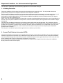
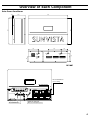
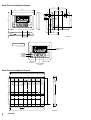
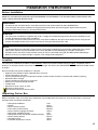
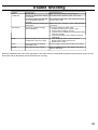
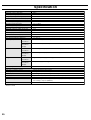
MODEL
JH-3500U
Solar Power Conditioner
INSTALLATION &
OPERATOR’S MANUAL
JH-3500 )
Grid - Interactive 1-Phase Inverter for Photovoltaic System
Ver.1.0
Page
• Notice for Users in the USA ................................. i
FCC Statement ....................................................... i
• IMPORTANT SAFETY INSTRUCTIONS ............... ii
• Features ................................................................. 1
Outline of Grid - Interactive Home PV system ........ 2
Required Condition for Grid-Interactive Operation ... 3
• Overview of Each Component ............................. 4
• Installation Instructions ....................................... 6
Before Installation .................................................. 6
Location ................................................................. 6
Unpacking Carton Box ........................................... 6
Required tools or items ........................................... 7
• Installing Solar Power Conditioner ..................... 8
• Electrical Connection ......................................... 11
Before Connecting ................................................ 11
• Wiring Solar Power Conditioner ........................ 13
• Connecting to DC Disconnect ............................ 15
• Connecting to AC Disconnect ............................ 17
• Installing Solar Power Conditioner Display ...... 19
• Test Running ....................................................... 22
Checking DC Voltage from PV Array ..................... 22
Checking AC Voltage from Grid ............................ 22
Test Running ........................................................ 23
Reinstalling Lower Front Panel .............................. 23
• Changing Operating Parameter ......................... 24
• Parameter and its Description ........................... 27
• Trouble Shooting ................................................ 28
• Specification ....................................................... 29
Notice for Users in the USA
FCC Statement
WARNING - FCC Regulations state that any unauthorized changes or modifications to this equipment not expressly approved by
the manufacturer could void the user’s authority to operate this equipment.
Note: This equipment has been tested and found to comply with the limits for a Class B digital device pursuant to Part 15 of the
FCC Rules.
These limits are designed to provide reasonable protection against harmful interference in a residential installation. This
equipment generates, uses and can radiate radio frequency energy and, if not installed and used in accordance with the
instructions, may cause harmful interference to radio communications. However, there is no guarantee that interference will not
occur in a particular installation. If this equipment does cause harmful interference to radio or television reception, which can be
determined by turning the equipment off and on, the user is encouraged to try to correct the interference by one or more of the
following measures:
• Reorient or relocate the receiving antenna.
• Increase the distance between the equipment and receiver.
• Consult the dealer or an experienced radio/TV technician for help.
i
IMPORTANT SAFETY INSTRUCTIONS
SAVE THESE INSTRUCTIONS
This manual contains important safety instructions for JH-3500U that shall be followed during the installation and
maintenance of the solar power conditioner.
To reduce the risk of electrical shock, and to ensure the safe installation and operation of the solar power conditioner,
the following words appear throughout this manual to inform you of or alert you something may cause dangerous
situation or safety instructions must be followed.
WARNING : May cause serious injury or kill a person unless the instructions are followed.
CAUTION : May harm or damage a person unless the instructions are followed.
NOTE
: Important information when installing or using the solar power conditioner.
General Safety Precautions
WARNING
• Follow all cautions and instructions marked on the solar power conditioner and this manual.
• Check all electrical connections to be firm and secure;
failure to do so may result in solar power conditioner from heat, smoke, and or fire.
• Never use the solar power conditioner except for the grid connected photovoltaic (hereafter called PV) power
system.
• Refer all installations of the solar power conditioner to certified personnel only after receiving prior approval
from a power company.
• Installation of the solar power conditioner and other devices in improper locations may cause smoke or fire
from each device.
• To reduce risk of electrical shock during installation or servicing, turn off all AC and DC disconnects.
CAUTION
• All electrical installations should be done in accordance with the local and national electrical codes ANSI /
NFPA70.
NOTE
• This solar power conditioner contains no user serviceable parts. Return the unit to a SHARP authorized
service center for maintenance.
•
symbols in the solar power conditioner and in this manual indicate grounding.
symbols in the solar power conditioner indicate “on” and “off” symbols. “
” is “on” symbol and “
” is
•
“off” symbol.
• Never exceed the voltage of more than 380V, which is the maximum system voltage of the solar power
conditioner.
ii
Features
Standard features of the solar power conditioner are:
• High output power inverter with HF transformer.
The solar power conditioner has a maximum output power of 3.5kW at ambient temperatures up to 40°C. The maximum
input from PV array is 4.5kW. And the solar power conditioner is equipped with a high frequency (HF) transformer to isolate
the PV array and the grid.
• Maximum power point tracking function on Multi-PV strings.
A maximum 3 PV strings can be input to the solar power conditioner. The maximum power point tracking function is
available on the solar power conditioner, and maximum power of each PV string can be output individually. This function
enables flexible layout of PV modules regardless of the type or the location.
• High efficiency and long operating life
The high frequency isolation transformer contributes to light weight of the solar power conditioner. The maximum conversion
efficiency is more than 92%.
• Equipped with LCD display
The LCD display shows the AC output power of the conditioner in real time as well as the accumulated power and amount
of avoided CO2 emission.
• UL Listed
The solar power conditioner provides islanding protection and satisfies US safety operating standards and code
requirement. It is UL Listed (UL 1741-1999). NEC 690 building code requirements for PV may be met with the optional
ground fault protection.
• Lightning Protection
This solar power conditioner has a lightning protection device on both DC and AC sides. EXTERNAL DEVICE IS NOT
REQUIRED.
1
Outline of Grid-Interactive Home PV System
The home PV system is a product for grid connection that includes the following components: PV modules that convert light into DC
electricity, a solar power conditioner that changes DC into AC and blends the power with the utility, a DC disconnect to break
the connection between the PV modules and the power conditioner, and an AC disconnect to break the connection between the
load center and the power conditioner. The system is connected to the grid through the AC load center.
When the system produces more energy than is consumed in the home, the excess power is supplied to the grid.
Grid
PV Array
AC
Load
Center
Watt-Hour
Meter
DC
Disconnect
PV Module
PV String
PV String
Solar Power
Conditioner
(JH-3500U)
AC
Disconnect
Display
The JH-3500U incorporates anti islanding protection and meets the requirements of UL 1741, which ensures the customer of the
safest PV power generation possible. The JH-3500U includes an internal ground fault detector interupter (GFDI) in compliance with
NEC 690 building code requirements.
The JH-3500U has also been tested to FCC class B requirements, in order to minimize radio and TV interference.
2
Required Condition for Grid-connected Operation
The solar power conditioner meets the following requirements for connection to the grid:
1. Islanding Protection
The power conditioner will shut down if the power from the grid becomes abnormal or fails. This will provide safety to the
people working on power lines and protect the home circuits and power conditioner.
The solar power conditioner continually monitors the voltage and frequency of the grid through an internal control circuit. It will
detect an abnormal condition or failure of the grid. Abnormal conditions include AC overvoltage, AC undervoltage, AC
overfrequency, and AC underfrequency. The solar power conditioner immediately shuts down and disconnects from the grid
should any of the above conditions occur.
Per UL 1741, the solar power conditioner will stop within 2 seconds should the grid voltage be lower than 211V AC or higher than
264V AC. The solar power conditioner will stop within 1 second should the frequency of the grid be lower than 59.3Hz or higher
than 60.5Hz.
The solar power conditioner incorporates two functions to detect and prevent islanding operation. This is important when the
output of the power conditioner and the power consumption of the home are well balanced and the voltage or the frequency of the
grid does not change during a power failure, resulting in the power failure not detected. This is avoided with a passive system
that detects a jumping voltage phase, and an active system that detects frequency shift that stops the power conditioner
operation within 2 seconds.
The solar power conditioner display indicates grid-off status to indicate a power failure.
2. Ground Fault Detector Interrupter (GFDI)
The ground fault detector interrupter is the protection facility for the PV system which is required by UL1741. This function will
monitor the ground current of the PV array at the detect circuit, and if the current is more than 1A, the solar power conditioner
stops to shut down the ground current. The solar power conditioner display indicates ground fault status. In this case, the solar
power conditioner will not restart automatically and requires a manual start.
A fuse (rated 1A) will also detect the ground fault and if the fuse blows out by the ground fault, the solar power conditioner
display shows that status on the display.
3
Overview of Each Component
Solar Power Conditioner
192
600
450
450
11.4
200
8
φ2
8
φ2
148
8
φ2
100
67
8
φ2
192
152
DC Terminal Block
for PV string
DC Input Switch
G
Display Jack
AC Terminal Block
GFDI (Ground Fault
Detector Interrupter) Fuse
4
Solar Power Conditioner Display
51.6
45.6
136.8
83.5
7.0
116.6
10
27.8
26.8
46.0
SOLAR POWER CONDITIONER DISPLAY
POWER
BACK
LIGHT
RESET
DISPLAY
MODE
CO 2
12.0
45.8
57.8
32.8
20
(unit:mm)
Name of Parts
LCD DISPLAY
PANEL
POWER
POWER
BUTTON
RESET
BUTTON
RESET
SOLAR POWER CONDITIONER DISPLAY
BACK
LIGHT
DISPLAY
MODE
CO 2
BACK LIGHT
CO2 BUTTON
BUTTON
DISPLAY MODE
BUTTON
Solar Power Conditioner Bracket
40
566
59
6.5
18
82
125
20
-φ
6.
5
452
186
2
φ1
42.2
70
70
70
70
70
70
70
71.8
(unit:mm)
5
(unit:mm)
Installation Instructions
Before Installation
READ ALL THE INSTRUCTIONS AND CAUTIONS MARKED ON THIS MANUAL, THE SOLAR POWER CONDITIONER, AND
THE PV ARRAY BEFORE INSTALLATION.
WARNING
• All electrical work should be done in accordance with local and national electrical codes ANSI/NFPA70.
• Connecting the solar power conditioner to the grid should only be done after receiving prior approval from the power
company and performed only by a Sharp certified installer.
CAUTION
• The solar power conditioner is approximately 57 lbs. in weight. To avoid the damage of the solar power conditioner or the
installer, do not drop the solar power conditioner.
• To avoid the risk of fire and the malfunction of the solar power conditioner, the open circuit voltage of each string should
be lower than 350V and the short circuit current of each string should be lower than 10A.
NOTE
• The National Electrical Code (NEC) requires that the solar power conditioner be connected to a dedicated circuit, and no
other outlets or device may be connected to this circuit. (See NEC section 690-64(b)(1)). The NEC also imposes
limitations on the size of the inverter and the manner in with it is connected to the grid. See NEC Section 690-64(b)(2).
• When the PV array is exposed to light, it supplies a DC voltage to this equipment.
Location
The solar power conditioner should be installed outdoors and the solar power conditioner display indoors. Installation of these
devices in an improper location may cause smoke or fire danger. Also refer to the IMPORTANT SAFETY INSTRUCTIONS section
on page ii.
Do not install the solar power conditioner in a location:
• Higher than the altitude of about 3,000 feet above sea level
• Prone to damage by sea water
• Close to volatile corrosive gas or liquid (for example, locations where chemicals are processed, feedlots or poultry)
• Exposed to direct sunlight
• Prone to flooding or high levels of snow pack
• Minimal or no air flow and high humidity
• Condensation
• Exposure to steam, vapor, or water
• Exposure to direct cool air
• Near television antenna or antenna cable
Unpacking Carton Box
Before installation, make sure all the items listed below are included within the carton box. If any of these items is missing or
damaged, notify your dealer immediately.
•
•
•
•
•
•
•
•
•
•
Solar power conditioner
Bracket
Screws (for the bracket)
Flat washer (for the bracket)
Screws (for the hanging the bracket)
Solar power conditioner display
Wiring cable for the solar power conditioner display
Screws (for the display)
Operation manual
Installation & Operator’s manual
1 unit
1 piece
10 pieces
10 pieces
1 piece
1 unit
1 piece
2 pieces
1 piece
1 piece
6
Required tools or items
Besides the supplied items on the previous page, the following tools or items are necessary.
Tools:
• Measuring tape
(longer than 1 m)
• Screw drivers
Phillips and Flat-head
• Electric driver
Torque: 0.78~3.4 N.m
• Nipper
• Hammer
• Pliers
• Wire strippers
• Utility knife
• Socket wrench and fittings
• Torque wrench
• Open-end wrench
• Electric drill
• Drill bits
∅6mm, 7mm, 8.5mm
• Cord reel
• Ladder (if necessary)
• Stepladder
• Low-voltage gloves
• Helmet
• Waste cloth
• Pencil or pen
• Cable tie
• Insulating tape
• Sealing putty
• Multimeter
Max usable DC voltage: more than 400V
• Frequency counter
• Ground tester
• Level
• Calculator
Items:
•
•
•
•
Grounding wire (AWG 10)
Wiring cable
Conduit pipe
Conduit hubs
• AC disconnect
• DC disconnect
7
(refer to page 13)
(3/4”)
(For 3/4” holes, Liquidtight and wet-location hubs that comply with
the requirements of UL 514B)
2. Attach the bracket to the wall. A hole allocated on the upper side of the horizontal center is for
hanging the bracket.
Tighten included screw which is intended for hanging it on the wall (not completely tighten,
some spacing to hang the bracket is needed). This screw does not need the flat washer. And
then, hang the bracket to the screw.
3. Tighten ten pieces of included screws to fix the bracket. These screws need flat washers.
At the end, Tighten all the screws for hanging completely.
Remove metal debris created when tightening screws or drilling holes.
CAUTION
•
Be sure to use the included mounting bracket to insure that the solar power conditioner is water resistant.
4. Remove the A screw on the bottom of the solar power conditioner.
5. Place the solar power conditioner so that it is hooked on the upper and center hooks on the
bracket.
6. Hold the solar power conditioner firmly and pull the bottom part of it forward to confirm that it is
hooked on the bracket securely.
9
7. Seal the space between the mounting bracket and the wall with modified silicone sealant.
Sealing
Sealing
Sealing
8. Tighten A screw removed on step 3 through the lower hook of the bracket.
A
9. Confirm that the solar power conditioner is installed securely.
10
Electrical Connection
The solar power conditioner is the inverter to be connected to both the PV modules and the grid (AC 240 volt, 60Hz). Connections
must be performed according to the electrical wiring diagram below:
Photovoltaic
Module
Solar
Power
DC
AWG12(or14) Conditioner
disconnect
Main AC
load
center
AWG10(or12)
P
P(1)
AC
disconnect
15A
(Option)
20A
P(2)
AC
15A
(Option)
P(3)
15A
(Option)
N
400V DC or over
240V AC
DC
AWG10
AWG10
N(3)
N(2)
N(1)
Conduit
1A
Main House Grounding System
PV Frame Ground
AWG10
Conduit
Ground Fault Detector
Interrupter (GFDI) Fuse
Exclusive Cable(40m)
Before Connecting
1. Confirm the setting condition of the components composing the PV power system.
1 Confirm that the PV module, the DC disconnect, the solar power conditioner, and the AC
disconnect are securely installed.
CAUTION
• Installation of the PV module, the DC disconnect, and the AC disconnect must be performed following the setting manual
of each component.
• Grounding should be performed following this manual.
• Input and output circuits should be isolated from the enclosure.
2 Confirm that the PV module and the DC disconnect are wired.
11
NOTE
• Wiring of the PV module
· Number of PV modules in series should obey the condition that the open circuit voltage of the PV strings is not higher
than 350V DC when the ambient temperature is from -20°C to 40°C, and the minimum operation voltage is higher than 110V.
· The number of the PV strings must be three or less. The number of PV modules in series of each PV string can be
different if the above condition is satisfied. The short circuit current of each PV string must be lower than 10A.
• DC Disconnect
· Rated input voltage of the DC disconnect switch must be 400V DC or over.
· Grounding terminal must be connected to the PV frame and solar power conditioner.
• AC Disconnect
· The AC disconnect switch must be capable of disconnecting the 240V-30A / AC.
· Supply over current protection fuse of 30A.
· Grounding terminal must be connected to the solar power conditioner and the AC load center.
Ask SHARP authorized dealer for PV modules or the AC&DC disconnects if necessary.
3. Confirm that breaker on the DC disconnect is in OFF status. If it is in ON status, turn it to OFF
status.
4. Confirm that the dedicated breaker for the solar power conditioner on the AC load center, and the
breaker on the AC disconnect is in OFF status. If they are in ON status, turn them to OFF status.
12
Wiring Solar Power Conditioner
WARNING
• All the procedures must be performed by a certified installer.
• Wiring the solar power conditioner and the DC disconnect enclosure, or the AC load center (or the AC disconnect enclosure)
must be performed with conduit. Also, the wiring of the solar power conditioner to the solar power conditioner display
should be safe from abrasion, moisture, heat, UV, and other elements of risk.
• Completely cover the surface of the entire PV array with an opaque (dark) material before wiring the solar modules. The PV
array produces electrical energy when exposed to light and could create a hazardous shock condition.
• Do not operate with wet hands or when the body is wet, or on a wet surface. It may cause an electrical shock.
• Use low-voltage protective glove.
• Disconnect the PV array output cable and the module output cable when operating, or wear electrically insulated gear.
• Be sure to turn off the following before starting wiring; otherwise it may cause an electrical shock:
· the entire input breaker
· the dedicated breaker for the solar power conditioner on the distribution board
· the DC disconnect switch
· the dedicated breaker of the AC load center
· the AC disconnect switch
• Do not turn on the DC disconnect switch until the wiring operation is finished, and starts the operation of the solar power
conditioner.
CAUTION
• Unused cable opening must be capped to keep the enclosure watertight.
• Grounding operation is the responsibility of the certified installer.
• To avoid risk of fire or electrical shock, select proper insulation and size for wires .
• To reduce the risk of short circuits during installation or servicing of the solar power conditioner, use insulated tools.
NOTE
• All electrical installations shall be done in accordance with all local electrical codes and the National Electrical Code (NEC),
ANSI/NFPA 70.
• Use the cables of the designated size. The cables should be single copper conductor wires with a nylon jacket, and the
temperature rating of the cables should be more than 90°C with UV resistant coatings.
· Use AWG 10(or 12), for the AC cable between the solar power conditioner and the AC disconnect.
· Use AWG 12(or 14), for the DC cable between the solar power conditioner and the DC disconnect.
· Use AWG 10, for all grounding cables.
• Be sure to use a ring terminal or a fork terminal when connecting to the terminal with multi-stranded wire.
• Because of voltage drops and other considerations, larger sized cable (up to AWG10) are available.
The solar power conditioner has five cable openings (for 3/4” conduit) and their caps. Up to three openings can be
used for the connection with the DC disconnect enclosure, and one opening for the connection with the AC load center (or AC
disconnect enclosure). And wiring of the solar power conditioner and the solar power conditioner display uses an opening (for 3/4”
conduit). Unused openings must be capped to keep the enclosure watertight.
13
Before Wiring
Remove the front panel of the solar power conditioner.
1. Unscrew 4 screws, then, remove the lower part of the front panel of the solar power conditioner.
2. Two openings are available for DC disconnect. Choose which openings to use, and remove the
end cap of the opening. Don’t remove the caps of the openings which are not used.
AC Disconnect
DC Disconnect
(PV Strings)
(front)
Display
Bottom View of Solar Power Conditioner
14
Connecting to DC Disconnect
This section describes the connection between the solar power conditioner and the DC disconnect. The distribution of the
connection are the output cables from the PV string (maximum three pairs of cables) and a grounding cable from the DC
disconnect.
Follow all WARNING and CAUTION of Wiring Solar Power Conditioner (page 13).
GND terminal
DC terminal Block for
DC disconnect
G
1. Utilize AWG12 cables for DC input single copper conductor wire (positive and negative) from the
DC disconnect through the conduit. Up to three pairs can be connected to the solar power
conditioner. Each pair should be marked as one pair of cables which are connected to the same
PV string when installing the PV array.
Tape
Tape
2. Locate the grounding cable (AWG 10 single copper conductor wire) from the DC disconnect
enclosure. This cable should be also located in the same conduit pipe used for the DC cables.
3. Remove the jacket of only one of the positive cables (black) which is connected to the first
terminal block. The length of the exposed conductor should be long enough to connect to the
DC terminal securely, and short enough to avoid touching any part except the terminal. See
below for detail.
16mm±1mm
DC cable
13mm±1mm
grounding cable
4. Connect the cable to the positive terminal of the terminal block 1 (rightmost), and tighten the screw
firmly to crimp the cable.
- +
15
5. Return to step 3 for the negative cable (white) to connect to the negative terminal of the terminal
block 1.
If the polarity is reversed, the solar power conditioner cannot operate.
6. The next pair of cables should be connected to next left terminal block. Return to step 3 to
connect the cables.
7. If all DC cables are connected to terminal blocks, remove the jacket of the grounding cable
(AWG10 single copper conductor wire) in the same way (See step 3) .
8. Locate the grounding cable to the rightmost “GND” terminal of AC terminal block, and tighten the
screw firmly to crimp the cable.
GND
G
9. Confirm all the cables are correctly and firmly connected to the terminals of the solar power
conditioner.
16
Connecting to AC Disconnect
This section describes the connection between the solar power conditioner and the AC disconnect. The distribution of the
connection is the AC output cable from the solar power conditioner (one paired cable) and the grounding cable.
Follow all WARNING and CAUTION of Wiring Solar Power Conditioner (page 13).
CAUTION
• Use exterior cable or tube on the exterior part between the conditioner and the PV module.
NOTE
• The AC disconnect includes function of over current protect.
AC terminal Block
for AC disconnect
G
1. Use two AWG 12 cables for AC output single copper conductor wire (not included).
2. Remove the jacket of only one cable. The length of the exposed conductor should be long
enough to connect to the AC terminal securely, and short enough to avoid touching any part
except the terminal. See below for detail.
13mm±1mm
3. Connect one cable to the L2 terminal of the AC terminal block, and tighten the screw firmly to
crimp the cable.
Connect another cable (after performing step 2) to the L1 terminal, and tighten the screw firmly to
crimp the cable.
L1 L2
G
4. If two AC cables are connected to the terminal block, remove the jacket of the grounding cable
(AWG10 single copper conductor wire) in the same way. (See step 2)
17
5. Connect a grounding cable to the leftmost G terminal of the AC terminal block, and tighten the
screw firmly to crimp the wire.
GND
G
6. Confirm that all the cables are correctly and firmly connected to the terminals of the solar power
conditioner.
Confirm that all the screws never move if the connected cable is pulled or bent. Tighten all the
screws firmly again. Make tight, 25 year duration, high quality connections and terminations.
18
Installing Solar Power Conditioner Display
Follow all WARNING and CAUTION on Location of Installation Instructions (page 6).
WARNING
• Do not install the display outdoors, as it may be damaged leading to smoking or fire.
CAUTION
• Signal cable of the display should not be cut or fastened, as it may cause malfunction.
• Use the included signal cable to connect the solar power conditioner and the display.
• Do not pull the signal cable at the connector, as it may break the wire.
1. Insert the larger 4-pin connector of the signal cable to the display jack in the solar power
conditioner (listen for clicking sound that ensures it is locked in place).
2. Connect the ground cable to the ground terminal in the solar power conditioner,
and tighten the installed screw with Phillips screw driver.
3. Insert the flat-head screwdriver into the slits on the bottom of the display, and twist the screw
driver in the direction of the diagram to open the front cover(See below for detail).
4. When the front cover is opened (small clicking sound), remove the front cover.
5. Insert the smaller connector of the signal cable from the backside of the display.
19
6. Insert the cable into the slot.
INV
SVC
SETTING
ENTRY
SELECT
Slot
7. Insert the smaller 4-pin connector of the cable to the connector in the display.
(listen for clicking sound that ensures it is locked in place).
Installing Display in a Socket Box
If you want to install the display on a wall, refer to Installing Display onto a Wall.
1. Insert the cable into the groove on the backside of the display.
Groove
2. Position the display and tighten by included screws. If installed in the dual outlets, use A opening
for screws, and if in the four outlets, use B. Do not expose the cable to abrasion risk.
A
B
Socket Box
A
B
When the procedure is completed, hook the top of the front cover on the hook of the display, and push the bottom side of the
cover until you hear a clicking sound.
20
Installing Display on a Wall
If you want to install the display in a socket box, refer to Installing Display in a Socket Box.
1. Tighten the included two screws for the display into the wall (not completely tighten, leave some
spacing to hook the display).
2. Insert the cable in the vertical groove on the backside of the display.
If using the upper groove, remove the cover of the groove.
3. Hook the display at the two screw slots on the backside and secure it down in place.
When the procedure is completed, hook the top of the front cover on the hook of the display, and push the bottom side of the
cover until you hear a clicking sound.
21
Test Running
CAUTION
Confirm the following before testing
• All terminals are securely connected.
• All wires are connected.
• The exposed conductors have no short circuits.
• All the cables are joined and fixed in place with the cable ties.
• All the conduit hubs are tightened.
Checking DC Voltage from PV String
Checking must be performed on a sunny day.
1. If the PV modules are covered with sheets, remove them.
2. Remove the GFDI fuse.
3. Turn on the DC disconnect switch.
4. Set the positive probe of the multimeter to the positive terminal of a DC terminal block, and the
negative probe to the negative terminal of the same terminal block. The multimeter
voltage range should be set over 400V DC.
5. Confirm that the reading of the multimeter is more than DC140V.
6. Check the voltage and the polarity at all the DC terminal blocks in the same way.
Checking AC Voltage from Grid
1. Turn on the dedicated breaker for the solar power conditioner on the AC load center.
2. Check the voltage of the terminal at the AC disconnect. The value should be approx. 240 V, 60Hz.
If not, check whether the connection is correct.
3. Turn on the AC disconnect switch.
4. Check the voltage between L1 and L2 terminals in the AC terminal block. The reading of the
multimeter should be approx. 240 V, 60Hz. If not, check whether the connection is correct again.
5. Check the voltage between L1 and GND in the AC terminal block. And check the voltage between
L2 and GND in the AC terminal block. The reading of the multimeter should be approx. 120V 60Hz.
If not, check whether the connection is correct again.
22
Test Running
1. Turn on all the DC wiring switches, and confirm that “d-47” is displayed on the LCD display. If “d47” is not displayed, the DC connections are incorrect. Check the polarity of all the DC wiring.
2. Turn off the AC&DC disconnect switches, and wait for 5 minutes to avoid the risk of electric
shock.
3. 5 minutes after the AC&DC disconnect is turned off, insert the GDFI fuse to the fuse socket. And
then turn on the AC&DC disconnect switches.
4. “d-47” will be displayed again. To clear previous error message, press “POWER” and “DISPLAY
MODE” buttons of the solar power conditioner display simultaneously. Then “CLEAR” will be
displayed for 5 seconds, and only “STOP” is displayed. If “d-47” is displayed again, the GDFI fuse
may be blown because some of the DC connections are incorrect. Check the polarity of all the DC
wiring.
5. Press “POWER” button of the solar power conditioner display for more than 2 seconds. Then,
“STAND-BY” is displayed, and the solar power conditioner starts the operation. “GRIDCONNECTED”, “RUN”, and the value of the output power are displayed.
6. If the operation is confirmed, press “POWER” button for more than 2 seconds to stop the solar
power conditioner.
Reinstalling Lower Front Panel
WARNING
The lower part of the front panel should be installed to avoid fire, smoke or malfunction from moisture.
1. Hang upper hook of the lower front cover onto the lower hook of the upper front cover; then
lower side of the lower front cover may be snapped closed.
1
2
2. Tighten four screws again. Do not tighten too much to avoid damage to the paintwork.
23
Changing Operating Parameter
CAUTION
The following operation includes the changing of the trip points of voltage or frequency. Never open the front cover of the
solar power conditioner display except by an authorized installer.
• To change the trip points, follow the instructions below.
• Perform changes while PV module is generating power during the daytime of a sunny day. Refer to the table on page 28 of the
value. The default value is designated by bold character.
1. Stop the power conditioner manually.
Press “POWER” button if it is operating.
“STOP” will be displayed on the display.
POWER
RESET
SOLAR POWER CONDITIONER DISPLAY
BACK
LIGHT
DISPLAY
MODE
CO 2
2. Remove the front cover of the display.
Refer to page 22.
3. Slide the both of two dip switches to “SVC” position with a narrow tool.
The first parameter number and its value appear on the display. If the display continues to
indicate “STOP”, one or both switches are left in INV position. In this mode, do not press “POWER”
button! (“POWER” is not indicated on the display. See below figure.), do not make the solar power
conditioner start operating. Confirm the both switches are in “SVC” position.
24
4. To change the parameter number, press “SELECT”.
5. When the target parameter number is displayed, press “SETTING” to change its value.
Only parameter numbers 1,2,7,9,11,12 can be changed.
25
6. When finished to changing all the target parameter values, press “ENTRY” to save the values.
7. When finished, slide the both dip switches to INV position.
9. Reinstall the front cover of the display.
26
Parameter and its Description
Parameter
Number
1
2
3
4
5
6
7
8
9
10
11
12
27
Parameter Description
AC over voltage
AC under voltage
AC over/under voltage stop time
AC over frequency
AC under frequency
AC over/under frequency stop time
Reversion timer
AC voltage suppression function
Islanding protection level
AC voltage suppression level
PV system maximum output power
Transmission address
Parameter value
260
211
2
0.5
-0.7
0.1
10
OFF
6
50
1.0
5
262
213
264
215
(60.5)
(59.3)
180
150
9
OFF
1.5
-
2.0
31
240
300
2.5
3.0
3.5
4.0
4.5
5.0
5.5
6.0
Trouble Shooting
Display
F-01
GRID OFF
No display
Check point
Power failure
Confirm AC Disconnect Switch
is turned on.
Confirm the dedicated breaker
of the distribution board is
tuned on.
Check AC terminal voltage with
multimeter
Check DC terminal voltage
with multimeters
E-23
(Internal)Temperature of power
conditioner inside is too high.
D-47
Check ground fault detector
interrupter fuse.
The mode is set to manual.
STOP
Countermeasure
Wait until utility recovers from blackout.
If AC Disconnect Switch is OFF, turn it ON.
If the dedicated breaker of the distribution board
is OFF, turn it ON.
Check the grid if voltage is under 240V between
L1 and L2.
If DC input voltage is under 135V,
1 Confirm DC disconnect switch is ON.
2 Confirm that sunlight is enough.
3 Confirm that PV module has no problem about
receiving sunlight.
4 Confirm the wiring of PV module and power
conditioner.
1 Turn the power "OFF" and wait until the
temperature inside becomes low.
2 Review the location.
If fuse is open, insert new fuse into fuse socket.
Press POWER button of the display and check
RUN is displayed.
When the conditioner does not recover regardless of the action above or it stops displaying other code except the above, turn DC
disconnect and AC disconnect switch off and refer for servicing.
28
Specification
Model
JH-3500U
Maximum system voltage (DC)
380 V
Rated input voltage (DC)
240 V
Range of operating DC voltage (DC)
110 V to 350 V
Maximum array short circuit current (DC)
10 A
Maximum operating current (DC)
22.5 A (7.5A for a DC input × 3)
Nominal output voltage (AC)
240 V
Operating voltage range (AC)
211 V to 264 V
Nominal output frequency (AC)
60 Hz
Operating frequency range (AC)
59.3 Hz to 60.5 Hz
Maximum continuous output current (AC)
15 A
Maximum continuous output power (AC)
3500 W
Rated output power
3000 W
Peak conversion efficiency (%)
92 %
Power factor
More than 0.95 (more than rated output power 1/8)
Total harmonic distortion [ THD ] (%)
Less than 5%
Operating temperature
-4°F_to_104°F_(-20˚C to +40˚C)
Solar Power
Conditioner
Solar Power
32°F_to_104°F_(0˚C to +40˚C)
Conditioner
Display
Dimension
Solar Power
Width-x-Height-x-Depth_(23.62x17.72x7.56_inches)_(600×450×192_mm)
Conditioner
Solar Power
Width-x-Height-x-Depth_(5.39x4.61x0.79_inches)_(137×117×20_mm)
Conditioner
Display
Weight
Solar Power
Approx._62_pounds_(Approx. 28 kg*)
Conditioner
Solar Power
0.5_pounds_(Approx. 0.2 kg)
Conditioner
Display
Enclosure type
3R
Main Circuit System
Solar power conditioner system
Voltage stiff current control system
Switching system
PWM (pulse width modulation) system
Insulator system
Built-in high frequency insulating transformer system
Electric system
1-phase 2-wire system(connected to 1-phase 3-wire system)
Protection
Grid-connected protection
AC Over Voltage / Under Voltage, AC Over Frequency / Under Frequency detection
Ground fault protection
DC detector / interrupter
anti-islanding component (IEEE929)
* Bracket included
29
SHARP CORPORATION
Printed in Japan
Doc. NO. 0000