1
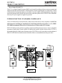
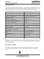
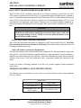
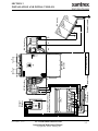
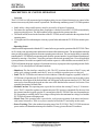
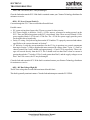
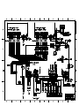
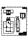
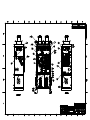
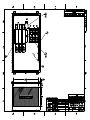
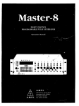
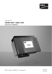
OPERATION and MAINTENANCE
MANUAL
for
MODEL PV-225208
225 kW Grid-Tied Photovoltaic Inverter
Document #151811
Revision C November 26, 2003
IMPORTANT SAFETY INSTRUCTIONS
SAVE THESE INSTRUCTIONS - THIS MANUAL CONTAINS IMPORTANT INSTRUCTIONS FOR XANTREX TECHNOLOGY MODEL PV-225208 GRID TIED PHOTOVOLTAIC
INVERTER THAT SHALL BE FOLLOWED DURING INSTALLATION AND MAINTENANCE
OF THE PV-225208.
Xantrex Technology Inc.
161-G SOUTH VASCO ROAD
Livermore, CA 94550
(925) 245-5400
Copyright 2003, Xantrex Technology Inc.
Table of Contents
Product Description ................................................. Section 1
Introduction ........................................................................... 1-1
Major Components ................................................................ 1-1
Control Components .............................................................. 1-2
Interconnection Standards Compliance ................................. 1-3
Specifications ........................................................................ 1-4
Equipment Symbol ................................................................ 1-4
Safety .............................................................................. Section 2
Safety Features ...................................................................... 2-1
Isolation Procedure ................................................................ 2-2
Installation And Initial Turn-On ........................ Section 3
Isolation Transformer Requirements ..................................... 3-1
Torque and Wire Gauge Specifications................................. 3-1
Installation Instructions ......................................................... 3-2
Interconnection Wiring .......................................................... 3-4
Initial Turn On Procedure ...................................................... 3-6
Operation .................................................................... Section 4
Description of System Operation .......................................... 4-1
Operation Features................................................................. 4-2
Operator Interface .................................................................. 4-3
Manual State Transitions ....................................................... 4-5
Automatic State Transitions .................................................. 4-6
Auto-Restart Feature ............................................................. 4-7
Isolation Procedure ................................................................ 4-7
Turn-On Procedure ................................................................ 4-7
Troubleshooting ........................................................ Section 5
General .................................................................................. 5-1
Alarms and Fault Conditions ................................................. 5-1
Preventative Maintenance .................................... Section 6
Periodic Maintenance ............................................................ 6-1
Isolation Procedure ................................................................ 6-2
Turn-On Procedure ................................................................ 6-2
Appendix ...................................................................... Section 7
Fault Codes ............................................................................ 7-1
Read/Write Parameter Menu ................................................. 7-1
Drawings List ........................................................................ 7-4
Warranty and Certifications .................................................. 7-4
SECTION 1
PRODUCT DESCRIPTION
INTRODUCTION
The Xantrex Technology Model PV-225208 is a current following grid tied photovoltaic inverter, utilizing
state-of-the-art IPM (Intelligent Power Module), insulated gate bi-polar transistors (IGBT’s) and gate drive
circuits to allow interface of a photovoltaic array with a utility grid. The PV-225208 consists of an inverter
bridge, photovoltaic controller, and associated control electronics. The PV-225208 control software provides
for complete overall system control with a variety of protection and safety features.
MAJOR COMPONENTS
The major components of the PV-225208 are identified in Figure 1-1. Control components are identified in
Figure 1-2. For specific control components see Drawing No. 151808 located in Section 7 (Appendix).
Main Enclosure
This enclosure is NEMA-3R rated. The PV-225208 main enclosure contains the power electronic inverter
bridge, electrical and electromechanical control components, power supplies, system sensing circuits, and the
PV-225208 embedded control unit. Also found within the main enclosure are some of the system protection
devices (sense and control power fuses).
Figure 1-1
DOCUMENT: 151811
PV-225208 Photovoltaic Inverter
Operation and Maintenance Manual
Copyright 2003, Xantrex Technology Inc.
1-1
SECTION 1
PRODUCT DESCRIPTION
AC Interface Enclosure
This enclosure is NEMA-3R rated. The AC Interface serves as the connection between the isolation
transformer/utility and the PV-225208. This enclosure is where the AC line fuses and AC disconnect switch
reside. For specific control components see Drawing No. 151809 in Section 7 (Appendix).
DC Interface Enclosure
This enclosure is NEMA-3R rated. The DC Interface serves as the connection interface between the PV
array and the PV-225208. This enclosure is where the DC disconnect switch and DC contactor reside. For
specific control components see Drawing No. 151810 in Section 7 (Appendix).
CAUTION
The fuses within the PV-225208 are intended for protecting the PV-225208 control circuitry
only. They are not intended to provide protection for the PV array or external cabling.
Power Electronics Matrix
The power electronics converters are located at the top of the PV-225208 Main Enclosure. Each matrix is
comprised of switching transistors (IGBTs), transistor gate drive electronics, a laminated power bus, DC
capacitor bank, and an aluminum extrusion heat sink with a cooling fan. A fan is located above each matrix
heatsink.
The PV array is tied logically to the matrix DC bus via the DC interface enclosure. The embedded
control unit manages the transfer of power between the DC bus and the utility grid.
Operator Interface
The operator interface is located on the front door of the PV-225208 main enclosure. It consists of an On/Off
switch and a keypad with liquid crystal display for control and monitoring purposes. All interface components
are NEMA-3R rated. Refer to Section 4 for detailed operation instructions.
Inductor Enclosure
This enclosure is NEMA-3R rated. It contains the necessary filter components to insure the PV-225208 line
currents and voltages meet IEEE-519 and UL1741 harmonic distortion requirements. Mounted on the right
and left side of the lower enclosure are inductor fans to allow cooling of the line filter components within. This
enclosure also serves as the mounting base for the PV-225208 main enclosure.
CONTROL COMPONENTS
The following assemblies are contained within the PV-225208 main enclosure as shown in Figure 1-2. For
specific control components see Drawing No. 151808 in Section 7 ( Appendix).
Power Distribution Panel
This panel contains many of the Electro-mechanical, protective, and control power components necessary to support the operation of the PV-225208.
DOCUMENT: 151811
PV-225208 Photovoltaic Inverter
Operation and Maintenance Manual
Copyright 2003, Xantrex Technology Inc.
1-2
SECTION 1
PRODUCT DESCRIPTION
Power Control Unit (PCU)
The PCU is a Digital Signal Processor (DSP) based control board that performs numerous control and
diagnostic functions associated with PV-225208 operation. Its most significant tasks are control of PV-225208
electromechanical components and power electronics converters, signal conditioning for high voltage signal
inputs and communication with the operator interface panel and system sensors. The PCU also contains the
necessary DC power supplies to support its operation.
INTERCONNECTION STANDARDS COMPLIANCE
The PV-225208 has been tested and listed by Underwriters Laboratories to be in compliance with UL1741
Static Inverters And Charge Controllers For Use In Photovoltaic Power Systems, as well as IEEE929-2000 Recommended Practice For Utility Interface Of Photovoltaic (PV) Systems.
IEEE-929-2000 provides guidance regarding equipment and functions necessary to ensure compatible
operation of photovoltaic systems which are connected in parallel with the electric utility. UL1741 is
the standard applied by Underwriters Laboratory to the PV-225208 to verify it meets the recommendations of
IEEE-929-2000. Refer to both documents for details of these recommendations and test procedures.
F-F
E-E
Figure 1-2
DOCUMENT: 151811
PV-225208 Photovoltaic Inverter
Operation and Maintenance Manual
Copyright 2003, Xantrex Technology Inc.
1-3
SECTION 1
PRODUCT DESCRIPTION
SPECIFICATIONS
The PV-225208 has been designed for photovoltaic power systems, which operate within the following specifications. Application of the PV-225208 in a manner inconsistent with these specifications may cause damage
to the PV-225208 and other system components, and is a violation of the terms of the warranty.
Nominal AC Line Voltage
208 VAC, +10% - 12%
Maximum AC Line Current
695 ARMS (at low line voltage)
Nominal Line Frequency
60 Hz, +0.5 - 0.7 Hz
Continuous AC Output Power
225.0 kW @ 208 VAC 3 Phase
PV Maximum Voltage
600 VDC
Peak Power Tracking Window
330*- 600 VDC
PV Minimum Peak Power Tracking Voltage
330 VDC
PV Maximum Operating Current
Maximum PV Array Short Circuit Current
710 ADC
1100 ADC
PV Configuration
Monopolar negative grounded
Operating Temperature
**- 20 to 50° C
Storage Temperature
- 40 to 50° C
Maximum Ambient Temperature Rating
50° C
Relative Humidity
To 95%, Non- condensing
Elevation
Derated above 6,600 feet
Dimensions (in inches)
87 X 102 X 27
Weight
Approx. 1935 lbs.
Enclosure Type
NEMA 3R
UL Listing File
File- E199356
*Dependent on actual AC line voltage. Refer to Section 4 for detail on the minimum power tracking voltage.
**If ambient temperature is between -20 to 0° C, the unit must be powered up in standby for at least one
hour prior to going on-line.
EQUIPMENT SYMBOL
Chassis ground – Customer supplied system ground connection point. This symbol may be found near
a stud within the main enclosure. It is provided as a location to bond the electrical system equipment
ground.
DOCUMENT: 151811
PV-225208 Photovoltaic Inverter
Operation and Maintenance Manual
Copyright 2003, Xantrex Technology Inc.
1-4
SECTION 2
SAFETY
SAFETY FEATURES
WARNING
The PV-225208 enclosure contains exposed high voltage conductors. The enclosure
doors should remain locked, except during maintenance or testing. These servicing
instructions are for use by qualified personnel only. To reduce the risk of electric
shock, do not perform any servicing other than that specified in the operating
instructions unless you are qualified to do so. Do not open the cabinet doors if
extreme moisture is present (rain or heavy dew).
On/Off Switch
The PV-225208 incorporates a maintained position on/off switch located on the front door of the main enclosure. Under normal conditions, the on/off switch is in the on position. Turning the switch to the off position will
initiate a controlled shutdown of the PV-225208 and open the A/C contactor within the unit. The A/C contactor
cannot be closed unless the switch is in the on position. The PV-225208 is prevented from being restarted until
the on/off switch is turned back to the on position. Cycling the on/off switch will reset the PV-225208 and
attempt to clear any system fault.
Main Enclosure Door Interlock Switch
The front door of the PV-225208 main enclosure is equipped with an interlock switch to preclude operation in
the event of the front door being opened. It is required that the PV-225208 main enclosure door handle be
padlocked during normal operation.
WARNING
The PV-225208 will immediately shutdown if the front door is opened during operation. It is required that the PV-225208 main enclosure door handle be padlocked
during normal operations. Please make sure the unit is powered down, and isolated
from the utility grid and PV panels, prior to opening the front door. Allow 5 minutes for
any stored potentials to be discharged, prior to opening the unit.
Disconnect Switches
Both AC & DC switches are equipped with lockout hasps for personnel safety. The switch enclosure
door will not open while the PV-225208 is running. In addition, the switch handle and shaft provide a door
interlock. The door cannot be opened when the switch is in the “on” position. The PV disconnect switch is
equipped with an auxiliary contact block which enables the switch to be used as a load break PV disconnect.
In the event a disconnect switch is opened while the PV-225208 is processing power from the PV array, the
contact block will signal the PCU to stop processing power before the switch opens.
Fault Reporting
Any fault conditions are reported to the operator interface. The LCD will display a text description of
the fault. Refer to Section 5, Troubleshooting, for detailed descriptions of system fault conditions.
PV Ground Fault Detection
The PV-225208 is equipped with ground fault detection circuitry (see section 3, installation and section 7,
system schematic for further detail). Upon detection of 10 amps of ground fault current, the PV-225208
executes an orderly shutdown, and annunciates a ground fault at the operator interface. The PV-225208 will
remain faulted until the ground fault is remedied and cleared at the operator interface (see section 5, troubleshooting).
DOCUMENT: 151811
PV-225208 Photovoltaic Inverter
Operation and Maintenance Manual
Copyright 2003, Xantrex Technology Inc.
2-1
SECTION 2
SAFETY
Over/Under Voltage and Frequency
The over/under frequency and voltage detection setpoints have been chosen to be in compliance with
IEEE-929 and UL1741.
Fault Condition
(% of Nominal)
Voltage Range
Trip Time
VAC < 50%
VAC < 104
6 Cycles
50% < VAC < 88%
104 < VAC < 183
2 Seconds
88% < VAC < 110%
183 < VAC < 228
Normal Operation
110% < VAC < 137%
228 < VAC < 285
2 Seconds
137% < VAC
285 < VAC
2 Cycles
f < rated - 0.7
f < 59.3
6 Cycles
f > rated +0.5
f > 60.5
6 Cycles
Anti Island Protection
A digital phase-shift-loop (PSL) circuit is implemented in the DSP inverter controller to prevent
“Islanding” of the PV-225208.
The DSP continuously makes minor adjustments to the power factor phase angle above and below
unity. In the event of a utility outage, these adjustments destabilize the feedback between the inverter
and the remaining load, resulting in an over/under frequency or voltage condition. The PV-225208 then
performs an orderly shutdown. The fault condition will remain until the utility voltage and frequency have
returned to normal for 5 minutes.
This method has been extensively tested and proven to exceed the requirements of UL 1741.
ISOLATION PROCEDURE
The following procedure should be followed to de-energize the PV-225208 for maintenance:
WARNING
The terminals of the PV input may be energized if the arrays are energized. In
addition, allow 5 minutes for all capacitors within the main enclosure to discharge
after disconnecting the PV-225208 from AC and DC sources.
1.
2.
3.
4.
5.
Turn the on/off switch to the off position.
Open the DC interface (PV array) disconnect switch.
Open the AC interface disconnect switch.
Open the isolation transformer circuit breaker.
Install lockout devices on the isolation transformer circuit breaker and PV disconnect switch.
DOCUMENT: 151811
PV-225208 Photovoltaic Inverter
Operation and Maintenance Manual
Copyright 2003, Xantrex Technology Inc.
2-2
SECTION 3
INSTALLATION AND INITIAL TURN-ON
ISOLATION TRANSFORMER REQUIREMENTS
The PV-225208 UL1741 certification requires the use of a Xantrex Technology specified 225 kVA WYE/
WYE isolation transformer between the inverter AC output and the utility interconnection (See Appendix in
Section 7 for transformer dimensions and specifications. This custom 225 kVA isolation transformer is not part
of the 225 kVA inverter, but can be ordered as a separate item. If maintaining the listing to UL1741 is not a
requirement for your application, contact Xantrex Technology for a fact sheet describing the installation options and precautions for installing this inverter in a photovoltaic system that does not require UL1741 compliance.
WARNING
Xantrex Technology requires installing an isolation transformer between the PV225208 inverter and the point of utility interconnection. Failure to do so could result
in catastrophic damage to the PV-225208 as well as the utility distribution system
and will void the product warranty.
Inverter Side Isolation Transformer Requirements
The inverter side of the isolation transformer is configured as a WYE, and is rated for 208 VAC. The neutral
(X0) connection on the inverter side must be left floating. If the neutral is tied to ground, the inverter will
be damaged internally at power-up.
Utility Side Isolation Transformer Requirements
The utility side windings of the isolation transformer are configured WYE, and must match the voltage at the
utility inter-tie. Verify that the transformer supplied matches the voltage requirement. Also, the transformer is
supplied with a neutral connection on the utility side. Connection of this utility-side neutral does not affect the
operation of the inverter. Check local jurisdiction for their requirements regarding the connection of this
neutral.
Contact your Xantrex Technology distributor if you have any questions regarding isolation transformer
requirements.
TORQUE AND WIRE GAUGE SPECIFICATIONS
The following torque specifications are to be used on all electrical interfaces made during installation
of the PV-225208.
Torque Table
DOCUMENT: 151811
Terminal Block or Bolt Size
Torque Setting
3/8-16 Bolt (AC)
250 in lbs./28.2 Nm
Terminal Block (DC+, DC-,
& DC Neutral)
275 in lbs/31.1 Nm
PV-225208 Photovoltaic Inverter
Operation and Maintenance Manual
Copyright 2003, Xantrex Technology Inc.
3-1
SECTION 3
INSTALLATION AND INITIAL TURN-ON
The following table shows acceptable wire gauges to be connected to the PV-225208 AC and DC inputs.
Wire Gauge Table
Termination
Wire Range AWG
Compression Lug (AC)
Up to 4 600MCM-#2
Conductors Per Phase
Compression Lug (DC+ and
DC-)
Up to 8 600MCM-#2
Conductors for each (+) and
(-)
Terminal Block (DC Neutral)
Up to 2 350MCM-#6
Conductors
INSTALLATION INSTRUCTIONS
CAUTION
All wiring methods shall be in accordance with the National Electrical Code ANSI/
NFPA 70. All power conductors interfacing to the PV-225208 should be sized in
accordance with the National Electric Code ANSI/NFPA 70 and local codes. Large
gauge wire must have a minimum bend radius dependent upon the wire gauge (refer
to the National Electric Code, Article 373-6B). Take care to keep the wire bundles
away from any sharp edges which may damage wire insulation over time. Xantrex
Technology recommends using 250 MCM, 105 degrees C, minimum, copper wire
for all connections to the PV-225208.
Ventilation Considerations
Maintain a minimum of 12” clearance in back , front and both sides of the PV-225208 for proper cooling fan
operation.
Installation
1. Move the PV-225208 into place. Lift the PV-225208 from beneath the lower enclosure with a forklift as
shown in Figure 3-1. (See following page.)
2. Anchor the lower enclosure feet to the floor with a 1/2” anchor bolts.
3. Install all conduits needed for cable entry in the shaded areas of both AC and DC interface enclosures as shown in Figure 3-2. (See following page).
DOCUMENT: 151811
PV-225208 Photovoltaic Inverter
Operation and Maintenance Manual
Copyright 2003, Xantrex Technology Inc.
3-2
SECTION 3
INSTALLATION AND INITIAL TURN-ON
Lift Here
Figure 3-1
Cable Entry
Area
Cable Entry
Area
Figure 3-2
Array Grounding
NEC 690-41/42 requires the PV array to be earth grounded. The PV-225208 chassis is also bonded to the
PV safety ground terminal block. Refer to the system schematic in the appendix for further wiring configuration.
DOCUMENT: 151811
PV-225208 Photovoltaic Inverter
Operation and Maintenance Manual
Copyright 2003, Xantrex Technology Inc.
3-3
SECTION 3
INSTALLATION AND INITIAL TURN-ON
Ground Fault Detection
The PV-225208 is equipped with a ground fault detection circuit
and current transducer (CT1 in illustration). This circuit is active
when the PV array is grounded as described in the previous
section. In the event of a greater than 10 amp ground fault, the
PV-225208 will execute an orderly shutdown and annunciates a
ground fault at the operator interface. The PV-225208 will remain
faulted until the ground fault is remedied and cleared at the operator interface (see section 5, Troubleshooting).
CAUTION
The input and output circuits are isolated from the
enclosure and the system grounding, if required by sections 690-41, 690-42 and 690-43 of the National Electric
Code, ANSI/NFPA 70, is the responsibility of the installer.
CT1
INTERCONNECTION WIRING
CAUTION
To reduce the risk of fire, connect only to a circuit provided with 800 amperes
@208VAC, or 400 amperes @480VAC maximum branch circuit overcurrent protection in accordance with the National Electrical Code, ANSI/NFPA 70.
The following wires for connecting the PV-225208 to external devices are not provided by Xantrex Technology: (See installation diagram on pages 3-5.)
•
•
•
•
Connect 3-Phase 208 VAC inverter output (AC Disconnect switch) to terminals of the 208 VAC
inverter side of isolation transformer. The neutral on the inverter side of the isolation transformer
must be left floating. Ground loops will exist when the inverter starts switching, which will
cause the inverter to shut down due to phase over-currents and will result in damage to the
PV-225208. Also, insure that this neutral is not bonded to the isolation transformer frame. Be
sure to maintain proper phasing as shown in the system schematic found in Section 7.
Connect Isolation transformer grid side terminals 1, 2, and 3 to line circuit breaker. Be sure to maintain
proper phasing as shown in the system schematic found in Section 7.
PV frame ground to ground terminal block (TB3).
Connect PV+, PV-, and PV Safety ground to the DC interface enclosure’s designated terminations. See Section 7 for further detail .
CAUTION
When connecting external AC wires to the PV-225208, positive phasing sequence
must be maintained throughout the installation process. Refer to the System Schematic in Section 7 of this manual for proper phasing convention.
Install all wires listed above. Refer to the Appendix in Section 7 for layout of the AC and DC interface enclosures. Refer to the system schematic in Section 7 for more detailed terminal locations.
DOCUMENT: 151811
PV-225208 Photovoltaic Inverter
Operation and Maintenance Manual
Copyright 2003, Xantrex Technology Inc.
3-4
DOCUMENT: 151811
PV-225208 Photovoltaic Inverter
Operation and Maintenance Manual
Copyright 2003, Xantrex Technology Inc.
H0
A
B C
Chassis Gnd
AC Interface
X1 H1
Isolation
Transformer
X3 H3 X2 H2
X0
To Single Point Electrical
Distribution System Ground
A B C N
Circuit
Breaker
Wiring Diagram
PV-225208
Inverter
GND
PV-
DC Interface
PV+
Frame Ground
PV Array
SECTION 3
INSTALLATION AND INITIAL TURN-ON
3-5
SECTION 3
INSTALLATION AND INITIAL TURN-ON
INITIAL TURN ON PROCEDURE
The following must be performed by an approved Technician:
The following procedures are intended to verify correct installation and proper operation of the PV-225208.
These steps are to be followed sequentially. Do not continue if any of the steps or results are unclear. Refer to
Section 4 for a detailed description of system operation. Refer to Section 5 for fault condition descriptions and
troubleshooting. Refer to Section 7 for detailed system schematics.
•
•
•
•
•
•
•
•
•
•
•
•
Visual Inspection, Isolation Transformer WYE/WYE
Verify the isolation transformer circuit breaker is open.
If a phase rotation meter is available, verify proper phase rotation at the line side of the isolation
transformer circuit breaker.
Insure the neutral on the inverter side is left floating. If the inverter side neutral is tied to ground,
the inverter will not function properly. Also, insure that the neutral is not bonded to the
isolation transformer frame.
Verify the inverter 208 VAC conductors are connected to the isolation transformer.
If the wires are marked, verify they follow the sequence on the line side of the isolation transformer
and circuit breaker.
Verify the utility conductors are properly connected to the isolation transformer.
Visual Inspection, PV-225208
Insure AC and DC disconnect switches are opened.
Remove the front cover from the inductor enclosure, open the door of the main enclosure, and
disconnect enclosures and inspect.
Verify all wire connections are tight.
Inspect the fiber optic cables between the PCU and the matrix driver boards. All fibers should be
snap-locked into their respective receivers/transmitters.
Insure all connector jack screws on the PCU and matrix driver board are tight.
Verify AC phase connections landed at the AC interface enclosure.
Visual Inspection, PV Array Wiring
Verify the PV+, PV-, and PV safety ground are isolated from each other. The safety ground must not
be tied to PV-.
• Verify all PV fuses are installed.
•
Initial Power
Turn the On/Off switch, located on the front door to off.
With the DC disconnect switch opened, close one of the PV array string disconnect switches.
Carefully measure VDC across the PV +/- terminal block. The value should be the same as at the
PV array string disconnect switch. It should also be positive.
• Close the PV disconnect switch.
• Carefully measure VDC between the DC contactor negative (-) terminal and the DC switch positive
•
•
•
DOCUMENT: 151811
PV-225208 Photovoltaic Inverter
Operation and Maintenance Manual
Copyright 2003, Xantrex Technology Inc.
3-6
SECTION 3
INSTALLATION AND INITIAL TURN-ON
•
•
•
•
•
•
•
•
•
•
•
•
•
•
•
•
•
•
(+) terminal. The value should be the same as at the PV array string disconnect switch. It should also be
positive.
Open all PV string disconnect switches.
Close the isolation transformer circuit breaker.
Verify 208 VAC voltage across the AC disconnect switch. If a phase rotation meter is available,
verify proper phase rotation at the AC disconnect switch.
Close the AC disconnect switch.
Verify 208 VAC voltage across the AC line fuses F1-3.
System Verification
Upon applying 208 VAC power to the PV-225208, observe the operator interface panel. After approximately 15 seconds, the panel should finish initialization and will probably report a fault condition.
Remedy any faults reported. To clear a fault condition, press the <ENTER> key twice. If the fault message
does not change, the fault condition is still present. Most likely, any faults seen at this point will be related
to PV-225208 safety switches. To disable the door interlock switch with the main enclosure door opened,
pull the switch shaft out. It will lock in its ‘maintenance’ position. Once all faults are cleared the system will
read ‘Sleeping’ or ‘Keyswitch Disable’ depending on the position of the On/Off switch. To re-enable
interlock, push the shaft in and close the door.
Scroll up the menu until ‘Enter Read Parameter:’ is displayed.
Press <Enter>, then <19>. This is line voltage frequency being read by the PCU. It should read 60.0
+0.5, -0.7.
Verify the On/Off switch is in the ‘Off’ position.
Close the PV array string disconnect switches.
Close the PV-225208 DC disconnect switch.
Press <F2> on the operator interface panel. If the PV voltage is above the PV Start Voltage setpoint,
the second line should read ‘Waking Up’. Once the PV Start Time is exceeded, the PV-225208 should
transition to ‘Power Tracking’.
The power tracker was previously limited to 25% of PV-225208 rated power. Once the PV-225208 has
stabilized operation (approximately 20 seconds), scroll through the main operator interface panel menu.
Verify all phase voltages and currents are closely balanced.
Scroll to ‘Enter Read Parameter:’ Press <ENTER> then <17> <ENTER> to view ground fault
current value. This value should be equal to or very close to zero. Continue to monitor this value as
the PV-225208 is commanded to higher power levels.
Enter the write parameter menu and increase the ‘I PPT Max %’ to 50. Exit the write parameter
menu and verify all operating values are proper.
Continue to increment ‘I PPT Max %’ to 100. Depending upon solar conditions, the PV-225208 may not
operate at full power. If the PV array is not experiencing full sun, the PV maximum power tracker will
regulate the PV voltage to maintain maximum PV power output. To determine if the PV-225208 has
reached it’s maximum power output, enter <20> at the ‘Enter Read Parameter:’ ‘0’ means the PV-225208
has not reached maximum power, contrarily, ‘1’ means the PV-225208 has reached maximum power and
executed the modified peak power tracker to limit output power.
The PV-225208 is now fully operational.
DOCUMENT: 151811
PV-225208 Photovoltaic Inverter
Operation and Maintenance Manual
Copyright 2003, Xantrex Technology Inc.
3-7
SECTION 3
INSTALLATION AND INITIAL TURN-ON
Power Tracker Fine Tuning:
• All PV-225208 operating parameters have been set at the factory, based upon prior experience with PV
arrays. Contact your Xantrex Technology distributor for further information.
• It is recommended that the PV-225208 be watched during Wake-Up and Sleep Test. If the PV-225208
cycles between operating and sleeping at either of these times, the condition setpoints are not set properly
(refer to section 4 for detailed description of PV-225208 state transitions). The PV225208 should not
cycle if the setpoints are set properly.
NOTE
Some field adjustable parameters are password protected and may only be changed
by trained service technicians. In particular are parameters relating to utility protection setpoints. Any changes to these setpoints should be agreed upon by the
local utility and the equipment owner.
NOTE
Visually inspect the exterior surfaces for any damage (nicks, chips, exposed base
metal and scratches) that may have occurred during shipment or installation. Touch
up or recoat using White NISSEN Feltip Paint Marker, or equivalent to prevent
rust or corrosion.
DOCUMENT: 151811
PV-225208 Photovoltaic Inverter
Operation and Maintenance Manual
Copyright 2003, Xantrex Technology Inc.
3-8
SECTION 4
OPERATION
DESCRIPTION OF SYSTEM OPERATION
Overview
The PV-225208 is a fully automated grid-tied photovoltaic inverter. Manual interaction or control of the
inverter is necessary only in the event of a system fault. The following conditions govern PV-225208 operation:
•
•
•
•
Stable utility voltage and frequency must be present for all states of operation.
Fault states are automatic from any state of operation. A fault will cause the PV-225208 to immediately
stop processing all power. The fault condition will be reported to the operator interface.
The on/off switch, located on the front door of the PV-225208, must be switched to the on position for all
operating states.
Cycling the on/off switch attempts to clear any system faults and return the PV-225208 to normal operation.
Operating States
A state machine implemented within the PCU control software governs the operation of the PV225208. There
are five steady-state operating states and numerous intermediate transition states. The intermediate transition
states provide an orderly progression from one operating state to the next. The user has the ability to manually
transition the PV-225208 between operating states from the operator interface keypad. Manual transitions are
initiated by entering a ‘Goal State’, where the goal state is the desired operating state. Given all applicable
system parameters are within acceptable limits, and the request is valid within the state machine, the PV225208 will initiate the proper sequence of operations necessary to progress to the requested goal state. Refer
to Figure 4-3 for a description of valid state transitions.
• Shutdown: The line interface controller is idle. The PCU monitors the status of the PV array and
utility grid, waiting in standby until the PV array is available to produce power to the grid.
• Fault: The PV-225208 has encountered a fault condition. When this happens, regardless of the PV225208 state-of-operation, the PV-225208 will stop processing all power and execute an orderly system
shutdown. A description of the fault and fault code will appear on the operator interface LCD. The Fault
state may be cleared from the keypad once the cause of the fault has been corrected. See Section 5 for a
complete description of all fault codes.
• Manual Current: This operating state is provided to evaluate the existing PV array V-I characteristics. The PV controller regulates a constant amount of PV current as commanded by the user from
the operator interface keypad, up to the PV current limit of the PV-225208. If the user commands more
PV current than is available, the DC bus voltage will drop below the minimum bus voltage level and the
PV-225208 will return to Sleeping mode.
• Matrix Test: This operating state is provided to verify proper operation of the matrix and associated control electronics. There is no power transfer between the PV and utility in this mode.
• Power Tracking: This is the standard operating state of the PV-225208. The PV-225208 maximum
power tracker will demand maximum power from the PV array, given sufficient PV irradiance.
DOCUMENT: 151811
PV-225208 Photovoltaic Inverter
Operation and Maintenance Manual
Copyright 2003, Xantrex Technology Inc.
4-1
SECTION 4
OPERATION
The user should be aware of the following conditions governing PV-225208 state transitions:
• Utility power must be present for all states of operation.
• Fault states are automatic from any state of operation. A fault will cause the PV-225208 to immediately
stop processing all power. The fault condition will be reported to the operator interface LCD.
• Most PV-225208 faults are latching and must be cleared at the operator interface keypad before
transitioning to another operating state.
• The On/Off switch, located on the front door of the PV-225208, must be in the On position for all
operating states except Matrix Test, in which case it must be in the Off position.
OPERATION FEATURES
Fixed Unity Power Factor Operation
The Xantrex PV Series grid tied inverters maintain unity power factor during operation. The control software
constantly senses utility voltage, and constructs the output current waveform to match the utility voltage. The
PV line of inverters are not capable of operation without the presence of normal utility voltage, nor are they
capable of varying the output power factor off unity.
Utility Voltage/Frequency Fault Automatic Reset
In the event of a utility voltage or frequency excursion outside of preset limits, the PV-225208 will stop
operation and annunciate a fault at the operator interface. Once the utility voltage has stabilized within acceptable limits for a period of at least five minutes, the PV-225208 will automatically clear the fault and resume
normal operation. Voltage and frequency fault setpoints are detailed later in this section.
Active Island Detection
Much concern has been given to the possibility of an inverter causing a ‘utility island’ condition during
a utility power outage. An island condition is defined as grid tied inverter maintaining operation and
supporting a load that has been isolated from the utility power source. This requires the load to be
closely balanced to the output power of the inverter as well as having a resonant frequency close to
60Hz. Needless to say, this is an extremely remote possibility. To insure this condition does not occur,
the PV-225208 control software contains an active phase-shift-loop algorithm, which destabilizes a balanced
load, which may otherwise be capable of maintaining inverter operation in the absence of utility voltage. This
feature has been extensively tested and proven to exceed the safety requirements of UL-1741 and IEEE-9292000.
Ground Fault Detection
The PV-225208 is equipped with a ground fault detection circuit and current transducer. In the event of a 10
amp ground fault, the PV-225208 will execute an orderly shutdown and annunciates a ground fault at the
operator interface. (See Section 5, Troubleshooting).
DOCUMENT: 151811
PV-225208 Photovoltaic Inverter
Operation and Maintenance Manual
Copyright 2003, Xantrex Technology Inc.
4-2
SECTION 4
OPERATION
Current Imbalance Detection
In the event of phase-to-phase current imbalance of greater than 20% between phases, the inverter will execute an orderly shutdown, and annunciate a fault at the operator interface. See Section 5, Troubleshooting,
for further information on this fault condition.
DC Overvoltage Detection
In the event of DC voltage greater than 600Vdc, the PV-225208 will execute an orderly shutdown and
annunciate a fault to the operator interface. If DC voltage remains greater than 600Vdc, the PV-225208 may
be irreparably damaged. See Section 5, troubleshooting for further information on this fault condition.
Peak Power Tracking
The PV-225208 control software employs an active PV peak power tracker designed to maintain maximum
power output from the PV array at all times of operation. The peak power voltage point varies primarily
depending upon the temperature of the PV cells. The PV-225208 constantly seeks the optimum voltage and
current operating points of the PV array to maintain maximum PV power output. Upon PV wake-up, the
power tracker will increase power while ramping PV array voltage to the PV maximum power voltage reference setpoint (PPT V Ref). The change rate is governed by the power point ramp time setpoint (PPT Ramp
T). Once the PV voltage is ramped to the reference setpoint, the PCU begins to adjust the commanded PV
voltage around the reference setpoint, seeking maximum PV power. The power tracker may only adjust the
operating voltage +/- 20% of PPT V Ref. The PV maximum power voltage step and update rate are user
setable (PPT V Step and PPT Rate, respectively).
If available PV power is above the maximum allowable power level of the PV-225208, the power tracker will
increase voltage as needed to maintain output power below rated maximum.
The minimum operating voltage of the PV-225208 is 330 VDC. The power tracker will not track voltage
below this point, regardless of the reference voltage setpoint.
Automatic Sleep Test
Toward the end of every solar day, the PV-225208 automatically determines when to stop producing power
dependent upon the output power of the inverter. As the net output power of the PV-225208 nears zero, a
timer is started to allow the inverter to ride through any brief irradiance reductions.
OPERATOR INTERFACE
The operator interface display consists of two main menu levels: The read parameter menu and the
write parameter menu. The read parameter menu consists of all system parameters, the date and time.
These can be viewed any time the PV-225208 has control power.
The write parameter menu consists of a goal state sub-menu, and all system write parameters. The write
parameter menu is password protected and may only be changed by trained service technicians. In
particular are parameters relating to utility protection setpoints. These have been set in the factory to
DOCUMENT: 151811
PV-225208 Photovoltaic Inverter
Operation and Maintenance Manual
Copyright 2003, Xantrex Technology Inc.
4-3
SECTION 4
OPERATION
the limits mandated by UL1741. Any changes to these setpoints should be agreed upon by the local utility and
the equipment owner. The ability to adjust the voltage and frequency setpoints with respect to the actual utility
voltage and frequency has been provided as a simulation tool to verify the PV-225208 accurately detects and
responds to a utility excursion. This test should only be performed by a trained service technician. It is possible
to adjust the setpoints in a manner that will prevent the PV-225208 from functioning.
Upon system power up, the operator interface LCD will display the system operating state on the first
line. The second line will display the date and time. This is the standard display.
Refer to Section 7, Appendix for a complete description of all system read/write parameters.
NOTE
The operator interface display will reset itself to the standard display if there is no
input for 30 seconds.
Read
Parameter
Menu
Standard
Display
Password
Enter
Goal State
Password
Write
Parameter
Menu
Set Date/Time
Change
Parameters
Figure 4-1
Operator Interface Flow Chart
Figure 4-2
Operator Interface Keypad
Viewing Read/Write Parameters Values
To display any parameter, use the /\ or \/ keys on the operator interface keypad to scroll through the
read/write parameters. The \/ key will scroll downward through the menu and the /\ key will scroll
upward. Upon reaching the end of the menu, it will roll-over to the beginning.
DOCUMENT: 151811
PV-225208 Photovoltaic Inverter
Operation and Maintenance Manual
Copyright 2003, Xantrex Technology Inc.
4-4
SECTION 4
OPERATION
Write parameter values are password protected; however, they may be viewed in the read parameter
menu without entering a password. From the standard display press the /\ key. The display will read
‘Enter Parameter ID:’. Enter the desired write parameter ID, then press the ‘Enter’.
Refer to Section 7: Appendix, for a table of all read/write parameters and their descriptions.
Changing Write Parameter Values
From the standard display or anywhere in the read parameter menu, you may access the write parameter menu by pressing the <MENU> key. This will ask for a password. Enter the password and press
the <ENTER> button. Use the /\ or \/ key on the operator interface keypad to scroll through the write
parameters. To change the displayed parameter, press the <ENTER> button. Enter the desired value
and press <ENTER>. If the value entered is outside the acceptable range for the parameter, the original
value will remain. To leave the write parameter menu press the <MENU> button repeatedly until the
standard display shows on the LCD.
Refer to Section 7: Appendix, for a table of all read/write parameters and their descriptions.
Commanding Goal State Changes
From the standard display press the <MENU> key. This will ask for a password. Enter the password
and press the <ENTER> button. The LCD will prompt ‘Change Goal State?’. Press <ENTER> again.
The goal state menu will show on the LCD. Scroll through the goal state menu with the /\ or \/ keys
until the desired goal state is reached. Press <ENTER>. The LCD will prompt: ‘Press F4 to Confirm’.
Press <F4> and the PV-225208 will transition to this goal state. If the goal state requested violates the
conditions of the state machine, the PV-225208 will remain in the previous state of operation.
Setting the Date and Time
From the standard display enter the write parameter menu (see previous). From the ‘Change Goal
State?’ prompt, scroll up with the /\ key until date/time parameter is reached. Press the enter key. The
date/time will be replaced with an underscore. Enter the proper date/time in a six digit format. For
example: The date is entered month-day-year: April 28, 2002 is entered 042802 <ENTER>. The time
is entered in military hours-minutes-seconds: 4:30 pm is entered 163000 <ENTER>. If the date/time is
entered incorrectly the original value will remain. Press <MENU> to return to the standard display.
MANUAL STATE TRANSITIONS
Refer to previous sections on commanding PV-225208 goal states.
• Sleeping → Matrix Test → Sleeping:
Turn the On/Off switch to the Off position. Command the PV-225208 to Matrix Test. Once the user has
completed the test, command the PV-225208 to Sleeping. If the On/Off switch is turned to On while the
PV-225208 is in the Matrix Test state, the PV-225208 will transition to Sleeping.
DOCUMENT: 151811
PV-225208 Photovoltaic Inverter
Operation and Maintenance Manual
Copyright 2003, Xantrex Technology Inc.
4-5
SECTION 4
OPERATION
Figure 4-3
PV-225208 State Machine
• Power Tracking→ Manual Current→ Power Tracking or Sleeping:
Verify the PV manual current parameter (I Manual %) is set to the desired percent of rated. Command the PV-225208 to Manual Current mode from the operator interface keypad. While in the manual
current mode, the user may change the PV manual current parameter. However, the user may demand
greater current than the capacity of the PV array. If this causes the PV voltage to drop below the minimum
operating voltage (330 Vdc), the PV-225208 will transition to Sleeping.
To exit the Manual Current mode the user must manually command the PV-225208 to either Power
Tracking or Sleeping.
AUTOMATIC STATE TRANSITIONS
• Sleeping → Power Tracking → Sleeping:
The On/Off switch must be turned to the On position. Once the PV voltage exceeds the PV voltage
start setpoint (PV V Start) the PV-225208 will start a wake-up timer (PV T Start). If the PV voltage
remains above the PV start voltage setpoint for the duration of the wake-up timer, the PV-225208 will
transition to Power Tracking.
If the PV power drops below the PV power stop setpoint (PV P Stop) the PV-225208 will start a PV
sleep timer (PV T Stop). If the PV voltage and power remain below their respective setpoints for the
duration of the sleep timer, the PV-225208 will transition to Sleeping
DOCUMENT: 151811
PV-225208 Photovoltaic Inverter
Operation and Maintenance Manual
Copyright 2003, Xantrex Technology Inc.
4-6
SECTION 4
OPERATION
• Any State → Fault:
If the PV-225208 encounters a fault, regardless of operating state, it will transition to the Fault state. The
PV-225208 will remain in this state until the fault condition has been remedied and cleared via the front
panel.
A description of the fault will show on the first line of the operator interface LCD. The second line
of the LCD will read ‘Clear Fault?’. To clear a fault press <ENTER>. The PV-225208 will transition to
Sleeping. If the fault does not clear, the fault condition has not been corrected. If the ‘Clear Fault?’ message is not shown on the second line of the LCD, scroll through the read parameter menu with the /\ or \/
keys until the message appears.
AUTO-RESTART FEATURE
In the event of a utility voltage or frequency surge or sag, which causes the inverter to shut down, the
PV-225208 will automatically transition to a fault condition. Once the utility recovers for a period of five
minutes, the PV-225208 will automatically clear the fault, then resume normal operation.
ISOLATION PROCEDURE
The following procedure should be followed to de-energize the PV-225208 for maintenance:
1.
2.
3.
4.
5.
Turn the On/Off switch to the Off position.
Open the DC interface (PV array) disconnect switch.
Open the AC interface disconnect switch.
Open the isolation transformer circuit breaker.
Install lockout devices on the isolation transformer circuit breaker and PV disconnect switch.
WARNING
The terminals of the PV input may be energized if the arrays are energized. In addition, allow 5 minutes for all capacitors within the main enclosure to discharge after
disconnecting the PV-225208 from AC and DC sources.
TURN-ON PROCEDURE
Refer to Section 3 for a detailed first-time turn on procedure.
1. Remove any lockout devices from the isolation transformer circuit breaker and PV disconnect
switch.
2. Close the isolation transformer circuit breaker.
3. Close the AC interface disconnect switch.
4. Close DC interface (PV array) disconnect switch.
5. Turn the On/Off switch to the On position.
After a 15 second initialization period, the PV-225208 will automatically transition to ‘Waking Up’, given the
PV voltage is greater than the PV V Start setpoint.
DOCUMENT: 151811
PV-225208 Photovoltaic Inverter
Operation and Maintenance Manual
Copyright 2003, Xantrex Technology Inc.
4-7
SECTION 5
TROUBLESHOOTING
GENERAL
In the event of a fault, the PV-225208 will annunciate the condition at the operator interface. The PV-225208
will execute an orderly shutdown and remain faulted until the fault is cleared (manually or automatically).
In general, the operator should respond to any PV-225208 fault as follows:
1. The source of the fault should be sought by referring to the following chart.
2. Rectify the fault condition and attempt to clear the fault by cycling the on/off switch.
3. If the problem cannot be corrected, note and write down the fault code and description, then contact
your Xantrex Technology distributor for assistance or service.
ALARM AND FAULT CONDITIONS
WARNING
Lethal energy may be stored within each matrix assembly. Use extreme caution
when troubleshooting. After disconnect all sources of power, wait at least 5 minutes
for internal capacitors to discharge.
(H) - Fault triggered by hardware.
(S) - Fault triggered by software.
0000 - No Faults
No fault conditions are detected.
002C/012C - Matrix Over-Temperature (S)
The temperature of the matrix (002C Matrix 1; 012C Matrix 2) aluminum heat sink exceeded 85°C.
Possible causes:
• External cooling fan inoperable
• Air flow on heat sink impeded due to accumulation of debris
• Operation above rated ambient temperature for an extended period of time
002E - State Machine Failure (S)
Software has encountered an undefined state.
Attempt to clear the fault by either cycling control power or pressing the black reset button in the lower
left corner of the PCU. If the fault is sustained, replacement or service of the PCU will be necessary.
002F – Parameter Out Of Date (S)
Software has determined that the system variables within the operator interface panel do not match the
ones in the PCU. Generally this fault may be cleared and normal operation resumed.
0031 - Ground Current Fault (S)
The earth safety ground current has exceeded the maximum programmed value (Max Gnd Flt I).
DOCUMENT: 151811
PV-225208 Photovoltaic Inverter
Operation and Maintenance Manual
Copyright 2003, Xantrex Technology Inc.
5-1
SECTION 5
TROUBLESHOOTING
Possible causes:
• Inspect the PV array for ground faults.
• CT8 defective: Troubleshoot the ground fault CT8, located on the power distribution panel of the main
enclosure (see system schematic drawing in Section 7), using the procedures described in fault YY27.
0032 - PV Overvoltage (S)
The PV voltage has exceeded the maximum programmed limit (PV Max Volt).
Check the PV input voltage at the PV disconnect switch. If the voltage is below 600 VDC, clear the
alarm and restart the PV-225208.
0040 - In Programming Mode (S)
System is in reload PROM mode.
0042 - Bad Memory (S)
The static memory test failed upon system initialization. This fault is generally transient in nature.
Attempt to clear the fault by either cycling control power or pressing the black reset button in the lower
left corner of the PCU. If the fault is sustained, replacement or service of the PCU will be necessary.
0045 – Line Matrix Failure to Turn On (S)
0046 – Line Matrix Failure to Turn Off (S)
Software was not able turn on or turn off the indicated switching matrix.
Attempt to clear the fault by either cycling control power or pressing the black reset button in the lower
left corner of the PCU. If the fault is sustained, replacement or service of the PCU will be necessary.
0061 – Line AC Frequency Too Low (S)
The AC line frequency fell below the allowable limit.
This fault is self-clearing. Once the utility frequency has recovered within the acceptable operating
range, the PV-225208 will automatically clear this fault and resume normal operation after 5 minutes. If the
fault will not clear, verify the adjustable setpoint is below the actual utility frequency. If the fault is sustained,
contact your Xantrex Technology distributor for assistance or service.
0062 - Line AC Frequency Too High (S)
The AC frequency exceeded the allowable limit.
This fault is self-clearing. Once the utility frequency has recovered within the acceptable operating
range, the PV-225208 will automatically clear this fault and resume normal operation after 5 minutes. If the
fault will not clear, verify the adjustable setpoint is above the actual utility frequency. If the fault is sustained,
contact your Xantrex Technology distributor for assistance or service.
DOCUMENT: 151811
PV-225208 Photovoltaic Inverter
Operation and Maintenance Manual
Copyright 2003, Xantrex Technology Inc.
5-2
SECTION 5
TROUBLESHOOTING
0063 - AC Voltage Too Low (S)
The AC Inverter voltage fell below the minimum programmed limit (Min AC Volt).
This problem was caused by the utility. Clear the fault and restart the PV-225208.
Possible causes:
• High momentary load which forces the inverter to current limit
• Fuses F1, F2, F3, F4, F5 or F6 blown
• SSR-1 inoperable
• Contactor K1 inoperable
• Utility voltage fell below the allowable limit.
This fault is self-clearing. Once the utility voltage has recovered within the acceptable operating range,
the PV-225208 will automatically clear this fault and resume normal operation after 5 minutes. If the fault will
not clear, verify the adjustable setpoint is below the actual utility voltage. If the fault is sustained, contact your
Xantrex Technology distributor for assistance or service.
0064 - AC Voltage Too High (S)
The inverter controller voltage exceeded the maximum-programmed limit (Max AC Volt).
Possible causes:
• SSR-1 inoperable
• Contactor K1 inoperable
• Utility voltage exceeded the allowable limit.
This fault is self-clearing. Once the utility voltage has recovered within the acceptable operating range,
the PV-225208 will automatically clear this fault and resume normal operation after 5 minutes. If the fault will
not clear, verify the adjustable setpoint is above the actual utility voltage. If the fault is sustained, contact your
Xantrex Technology distributor for assistance or service.
012A - Interrupt Time-Out (S)
The PCU was not able to service the interrupt for approximately 1 second.
Attempt to clear the fault and restart the PV-225208 by pressing the black reset button on the lower left corner
of the PCU. If the fault is sustained, replacement or service of the PCU will be necessary.
0230 – Door Interlock Switch Open (H)
The door interlock lock switch located in the inside upper left corner of the main enclosure door is open.
If the switch is closed and the fault still registers on the front panel, isolate the PV-225208 from external power,
then:
•
•
Verify continuity across the switch contact block while the switch is closed.
Verify continuity between PCU-J2-5 and PCU-J3-3.
0430 - PV Auxiliary Switch Open (H)
DOCUMENT: 151811
PV-225208 Photovoltaic Inverter
Operation and Maintenance Manual
Copyright 2003, Xantrex Technology Inc.
5-3
SECTION 5
TROUBLESHOOTING
The dry contact auxiliary switch mounted to the PV disconnect switch has been toggled. The auxiliary
switch should be opened when the PV disconnect switch is open. If the fault will not clear when the PV
disconnect switch is closed:
• Isolate PV-225208 from utility power.
• Close PV disconnect switch and check continuity between PCU J3-3 and PCU J2-7. If there is no
continuity, inspect wiring between the PCU and the auxiliary switch (see page 2 of the system schematic
for further detail).
XX25/XX26 - Line Gate Drive Fault (S)
One of the IGBT gate drive boards signaled the PCU that there was a fault. The second two digits refer to
which matrix has the fault. XX25 refers to matrix 1 and XX26 refers to matrix 2. The particular device at
which the fault was detected is indicated by the first two digits of the fault code, as follows:
XX: 01 = Phase A+
02 = Phase A04 = Phase B+
08 = Phase B10 = Phase C+
20 = Phase CIf more than one phase faults simultaneously, the error code will contain the summation of phase fault
values. For example, if phase A+ and B+ of matrix 1 fault simultaneously, the error will read 0525.
Make sure the fiber optics for the device and matrix in question are properly connected to the driver
board. Similarly, make sure the fiber is properly connected at the PCU.
Clear the fault and restart the PV-225208. If the fault is sustained, contact your Xantrex Technology distributor
for assistance or service.
YY27/YY28 - Line Over-Current Fault (S)
Current in one phase of the matrix has exceeded the allowable limit. YY27 refers to matrix 1 and YY28 refers
to matrix2. The faulted phase is indicated by the first two digits of the fault code, as follows:
YY: 01 = Phase A
02 = Phase B
04 = Phase C
If more than one phase faults simultaneously, the error code will contain the summation of phase fault
values. For example, if phase A and C of matrix 1 fault simultaneously, the error will read 0527.
Possible causes:
• AC system wiring short: Inspect the AC power system for short circuits.
• PCU Power Supply is defective: Verify +/-15Vdc sources, referenced to analog ground, on the
PCU. There are labeled test points on the PCU circuit board. Note: There are two isolated +15Vdc
power supplies labeled +15Vdc and +15Vdc Drv. The +15Vdc Drv power supply provides power
for the matrix driver boards only.
• Faulty CT wiring: Verify the wiring between the PCU power supply and the CT is properly connected and undamaged. Refer to page 2 of the system schematic in Section 7.
• CT defective: Locate the current transducer for the matrix and phase in question (see control components drawing in Section 7). With a digital multi-meter measure the voltage from CT pins 1, 2, and
3 to chassis ground. Pins 1 and 3 should read approximately +15 and -15Vdc respectively. These
voltages are sourced directly from the PCU. Pin 2 should read less than 20mV when no current is
passing through the CT window. If Pin 2 reads greater than 20mV, and the supply voltages are on
DOCUMENT: 151811
PV-225208 Photovoltaic Inverter
Operation and Maintenance Manual
Copyright 2003, Xantrex Technology Inc.
5-4
SECTION 5
TROUBLESHOOTING
Pins 1 and 3 are correct, the CT may be damaged.
Clear the fault and restart the PCU. If the fault is sustained contact your Xantrex Technology distributor for
assistance or service.
0828 – PV Over-Current Fault (S)
Current through the PV CT has exceeded the allowable limit.
Possible causes:
• PV system wiring short: Inspect the PV power system for short circuits.
• PCU Power Supply is defective: Verify +/-15Vdc sources, referenced to analog ground, on the
PCU. There are labeled test points on the PCU circuit board. Note: There are two isolated +15Vdc
power supplies labeled +15Vdc and +15Vdc Drv. The +15Vdc Drv power supply provides power
for the matrix driver boards only.
• Faulty CT wiring: Verify the wiring between the PCU and the CT is properly connected and undamaged. Refer to the system schematic in Section 7.
• CT defective: Locate the current transducer for the PV leg in question (see control components
drawing in Section 7). With a digital multi-meter measure the voltage from CT pins 1, 2, and 3 to
chassis ground. Pins 1 and 3 should read approximately +15 and -15Vdc respectively. These voltages are sourced directly from the PCU. Pin 2 should read less than 20mV when no current is
passing through the CT window. If Pin 2 reads greater than 20mV, and the supply voltages are on
Pins 1 and 3 are correct, the CT may be damaged
Clear the fault and restart the PCU. If the fault is sustained contact your Xantrex Technology distributor
for assistance or service.
8021 - DC Bus Voltage High (H)
The DC Bus voltage has exceeded the maximum allowable limit.
This fault is generally transient in nature. Clear the fault and attempt to restart the PV-225208.
DOCUMENT: 151811
PV-225208 Photovoltaic Inverter
Operation and Maintenance Manual
Copyright 2003, Xantrex Technology Inc.
5-5
SECTION 6
PREVENTATIVE MAINTENANCE
PERIODIC MAINTENANCE
Xantrex Technology recommends that the following preventative maintenance be carried out on the
PV-225208:
Monthly intervals or as required:
NOTE
Visually inspect the exterior surfaces for any damage (nicks, chips, exposed base
metal and scratches). Touch up or recoat using White NISSEN Feltip Paint Marker,
or equivalent to prevent rust or corrosion.
Aluminum Extrusion Heatsink
Accumulation of dirt and debris on the aluminum extrusion heatsinks and fans will decrease the ability
to transfer heat, which can cause the PV-225208 to shutdown on over-temperature alarms. Inspect
the aluminum extrusion heatsinks and fans for accumulation of dirt and debris. Clean if debris is present.
Fan Operation
Verify proper operation of the heatsink cooling fans, located above the matrix heatsinks. The fans
operate when the K1 contactor is closed. Remove any debris from the fans.
Internal Circulation Fan:
Verify the internal circulation fan is operating whenever there is utility power applied to the
PV-225208.
Inductor Enclosure Cooling Fans:
Verify these fans operate whenever the PV-225208 is processing power.
Six month intervals:
(See Isolation Procedure located on page 6-2, and perform prior to the following)
Enclosure Seals
Inspect the enclosure access panel seal. If damaged, replace with equivalent closed cell foam
gasket. Call your Xantrex Technology distributor for factory replacements or specifications.
Electrical Connections
Inspect the condition of all wiring within the PV-225208. Inspect all wire crimps and connections for
damage caused from high temperature. Check for corrosion. Replace any damaged wires. Verify all
mechanical connections are sufficiently tightened. Verify all conduction surfaces are clean and free of
corrosion.
DOCUMENT: 151811
PV-225208 Photovoltaic Inverter
Operation and Maintenance Manual
Copyright 2003, Xantrex Technology Inc.
6-1
SECTION 6
PREVENTATIVE MAINTENANCE
Mechanical electrical connections will loosen over time. This is caused primarily by thermal cycling
during normal operation. As connections loosen, electrical impedance will increase at the connection,
eventually leading to fire and component damage. It is critical to check all electrical connections every
six months.
Inductor Enclosure
Access the inductor enclosure and remove any accumulated dirt and debris. Vacuum enclosure
whenever dust or dirt is present.
ISOLATION PROCEDURE
The following procedure should be followed to de-energize the PV-225208 for maintenance:
WARNING
The terminals of the PV input may be energized if the arrays are energized. In
addition, allow 5 minutes for all capacitors within the enclosure to discharge after shutting down the PV-225208.
1.
2.
3.
4.
5.
Turn the on/off switch to the off position.
Open the DC interface (PV array) disconnect switch.
Open the AC interface disconnect switch.
Open the isolation transformer circuit breaker.
Install lockout devices on the isolation transformer circuit breaker and PV disconnect switch.
TURN-ON PROCEDURE
Refer to Section 3 for a detailed first-time turn on procedure.
1. Remove any lockout devices from the isolation transformer circuit breaker and PV disconnect
switch.
2. Close the isolation transformer circuit breaker.
3. Close the AC interface disconnect switch.
4. Close the DC interface (PV array) disconnect switch.
5. Turn the on/off switch to the on position.
After a 15 second initialization period and a 5 minute wake up period, the PV-225208 will automatically begin
power tracking, given the PV voltage is greater than the PV start voltage setpoint.
DOCUMENT: 151811
PV-225208 Photovoltaic Inverter
Operation and Maintenance Manual
Copyright 2003, Xantrex Technology Inc.
6-2
SECTION 7
APPENDIX
FAULTS CODES
Refer to section 5 for detailed fault code descriptions.
H - Fault(s) triggered by hardware
S - Fault(s) triggered by software
Error
Code
Fault Source (s )
H/S
0000 No Faults
Error
Code
Fault Source (s )
H/S
0062 Line Frequency Too High
(S)
002C Matrix Over- Temperature
(S)
0063 Line Voltage Too Low
(S)
002E State Machine Failure
(S)
0064 Line Voltage Too High
(S)
002F Software Parameter Out of Date
(S)
012A Interrupt Time- Out
(S)
0031 Ground Current Fault
(S)
0230 Door Interlock
(H)
0032 PV Over- Voltage
(S)
0430 PV Auxiliary Contact Block
(H)
0040 In Programming Mode
(S)
XX25 Line Matrix Gate Drive
(S)
0042 Bad Memory
(S)
YY27 Line Matrix Over- Current
(S)
0045 Line Matrix Control Failure to Turn On
(S)
0828 PV Over- Current
(S)
0046 Line Matrix Control Failure to Turn Off
(S)
8021 DC Bus Voltage Too High
(H)
0061 Line Frequency Too Low
(S)
READ/WRITE PARAMETER MENU
Read-Only Parameters
Parame te rs
Current Operating
State
System Goal State
DOCUMENT: 151811
ID Type
1 Read
2
Read
Units
N/A
N/A
Data Limits
N/A
N/A
De fault
De s criptions
N/A
Curre nt State s :
0- Initilizing
1- Key- Disabled
2- Sleeping
3- Starting
4- Power- Tracking
5- Manual Current
6- Matrix Test
7- Faulted
N/A
Goal State s :
0- Shut Down
1- Power- Tracking
2- Manual Current
3- Matrix Test
PV-225208 Photovoltaic Inverter
Operation and Maintenance Manual
Copyright 2003, Xantrex Technology Inc.
7-1
SECTION 7
APPENDIX
Parame te rs
Fault Code
ID
Type
Units
Data Limits
3
Read
N/A
N/A
De fault De s criptions
N/A
See Fault Codes Above
4
Read
N/A
N/A
N/A
Inve rte r State s :
0- Shut Down
1- Standby
2- Starting
3- Main- Setting
4- On- Line
Line A- B Voltage
5
Read
Vrms
N/A
N/A
Line to Line Voltage
Line B- C Voltage
6
Read
Vrms
N/A
N/A
Line to Line Voltage
Line C- A Voltage
7
Read
Vrms
N/A
N/A
Line to Line Voltage
Line A Current
8
Read
Arms
N/A
N/A
Line B Current
9
Read
Arms
N/A
N/A
Line C Current
10
Read
Arms
N/A
N/A
Inverter Real Power
11
Read
kVA
N/A
N/A
Inverter Matrix
Temperature
12
Read
°C
N/A
N/A
Inverter State
PV State
13
Read
N/A
N/A
N/A
PV Voltage
14
Read
VDC
N/A
N/A
PV Current
15
Read
ADC
N/A
N/A
PV Power
16
Read
kW
N/A
N/A
Ground Fault Current
17
Read
Arms
N/A
N/A
Peak Power On/Off
18
Read
N/A
N/A
N/A
Inverter Frequency
19
Read
Hz
N/A
N/A
Maximum Inverter
Power
20
Read
kVA
N/A
N/A
DOCUMENT: 151811
PV-225208 Photovoltaic Inverter
Operation and Maintenance Manual
Copyright 2003, Xantrex Technology Inc.
PV State s :
0- Shut Down
1- Sleep
2- Wakeup
3- Online
4- Sleep- Test
0- O n
1- Off
Maximum Line Power
Recorded by PCU
7-2
SECTION 7
APPENDIX
Parame te rs
ID
Type
Units
Data Limits
De fault De s criptions
Maximum PV Power
21
Read
kW
N/A
1:1
Maximum Line Power
Recorded by PCU
Maximum Inverter
Current (phase A)
22
Read
Arms
N/A
1:1
Maximum Line Current
Recorded by PCU
Commanded PV
Current
23
Read
ADC
N/A
1:1
Maximum PV Current
Available to be
Commanded by the PV
Power Tracker
Maximum AC Voltage
32
Write
Volts
190 < V < 229
229
Maximum AC Voltage
fault setpoint *
Minimum AC Voltage
33
Write
Volts
183 < V < 220
183
Minimum AC Voltage
fault setpoint *
Maximum AC
Frequency
34
Write
Hz
59.3 < Hz <
60.5
60.5
Maximum AC Frequency
fault setpoint *
Minimum AC
Frequency
35
Write
Hz
59.3 < Hz <
60.5
59.3
Minimum AC Frequency
fault setpoint *
Maximum Ground
Fault Interrupt
36
Write Amps
1 < I < 20
10
Ground fault current
setpoint
PPT V Ref
37
Write
Volts
300 < V < 600
400
Peak Power Tracker
Reference Voltage
PV V Start
38
Write
Volts
300 < V < 600
440
PV power tracker wakeup voltage
PV T Start
39
Write
Sec
0 < T < 1200
300
Time delay for PV
wake- up
PV T Stop
40
Write
Sec
0 < T < 1200
20
Time delay for PV sleep
test
PV P Stop
41
Write
kW
0 . 2 < kW <
10.0
1.0
PV power point to begin
sleep test timer
* Inverter trips off line within two cycles on over/under voltage and frequency faults. It should be
noted that the voltage trip limits can be up to 1% off from the actual grid voltage at full load due to
the 1% regulation of the isolation transformer. The PV-225208 uses phase to phase voltage measurement
to detect the under/over voltage trip limits. For an unbalanced, single phase voltage variation of +10% and
-12% as per UL1741 the trip limits must be set to 220V for maximum AC voltage and 193V for minimum
AC voltage. Consult your local utility for their specific requirement.
DOCUMENT: 151811
PV-225208 Photovoltaic Inverter
Operation and Maintenance Manual
Copyright 2003, Xantrex Technology Inc.
7-3
SECTION 7
APPENDIX
Parame te rs
ID
Type Units
Data Limits
De fault De s criptions
I PPT Max %
42
Write
%
0 < % < 100
100
Percent of maximum allowable
PV power tracker mode current
I Manual %
43
Write
%
0 < % < 100
25
Percent of maximum allowable
PV manual mode current
Turns power tracker on or off. If
off the power tracker will
regulate voltage at the reference
setpoint.
0 = Off
1 = On
PPT Enable
44
Write
N/A
0 or 1
1
PPT Rate
45
Write
Sec
0.1 < T < 10.0
0.5
Power tracker update rate
PPT V Step
46
Write
Volts
0 < V < 10.0
1.0
Voltage perturbation step of
power tracker
WARRANTY AND CERTIFICATION
Xantrex Inverter Warranty Registration
Underwriters Laboratories Compliance Of Standard UL1741
DRAWINGS LIST
151828 : Schematic, System, Grid Tied PV Inverter, PV-225208
151807 : Envelope Drawing, Grid Tied Inverter, PV-225208
151808 : Enclosure, Main, Control Components, PV-225208
151809 : Enclosure, AC Interface, PV-225208
151810 : Enclosure, DC Interface, PV-225208
151812 : Transformer, 225 kVA, 3-Pole, 60 Hz, 98% Efficient, 208Y/120 or 480Y/277
DOCUMENT: 151811
PV-225208 Photovoltaic Inverter
Operation and Maintenance Manual
Copyright 2003, Xantrex Technology Inc.
7-4
Xantrex Technology, Inc.
Distributed Power Markets
161G South Vasco Road
Livermore, CA 94550 USA
Phone +1 925.245.5400
Fax +1 925.245.1022
XANTREX PV SERIES LIMITED WARRANTY AND REGISTRATION
Xantrex Technology warrants all equipment supplied to Customer under this purchase
order against defects in workmanship and material for a period of (12) twelve months
from delivery, provided that the equipment has been operated and maintained in
accordance with the service manual provided with the equipment. Should Customer
give Xantrex written notice of any such defects within the warranty period, and
Xantrex’s inspection confirms the existence of such defects, Xantrex shall correct the
defects, either by repair or replacement, at its sole option.
For wall-mounted products (generally, below 30 kW in rating), defective products must
be returned to Xantrex or it Authorized Service Center in the original or equivalent
packaging. The cost of transportation and insurance on items returned for service is at
the Customer’s expense. Return transportation and insurance expense shall be borne by
Xantrex.
For floor mounted inverter products (generally, 30 kW in rating and above), warranty
repairs or replacements are performed at the installation site. Xantrex’s material, labor,
freight and travel/living expenses associated with such repair or replacement shall be
borne by Xantrex.
In either case, Customer’s labor and travel/living expense shall be borne by Customer.
Xantrex will assume no expense, liability or responsibility for repairs made by or for
Customer without written authority from Xantrex. Xantrex shall not be responsible for
any consequential, incidental or similar damages.
THE FOREGOING WARRANTIES ARE IN LIEU OF ALL OTHER WARRANTIES, EXPRESS
OR IMPLIED, INCLUDING, BUT NOT LIMITED TO, THE IMPLIED WARRANTIES OF
MERCHANTABILITY AND FITNESS FOR A PARTICULAR PURPOSE.
Project Name
Customer PO #
Inverter Serial #
Delivery Date
______________________
______________________
______________________
______________________
Xantrex Authorized Signature:
Customer Authorized Signature:
________________________
________________________
________________________
Date
________________________
Date
D
D
Xantrex Technology Inc. PV-225208
Photovoltaic Inverter
Major Parts List
Assembly Description: Main Enclosure, Control Components, PV-225208
Xantrex Technology Assembly # 151808
Item #
Qty
Reference Designator
Xantrex Technology Part #
1
2
3
4
5
6
7
8
9
10
11
12
13
14
15
16
17
18
19
20
21
22
23
24
1
1
2
1
1
3
1
2
2
1
7
2
1
1
1
2
3
1
2
4
5
1
1
1
T1
T2
T3,T4,T5
K1
SSR1,SSR2
C4,C5
C1
CT1,2,3,4,5,6,8
B1,B2
B3
PS1
TB4
TB2,TB3
F4-12
F13,14
F7,8
F9-12
F4-6,13,14
S6
TB1
CT7
1-151751-01
1-151775-01
1-150209-02
1-151614-01
1-151615-01
1-151774-01
1-150204-03
1-112129-01
1-111196-01
1-151782-01
1-113712-01
1-151187-01
1-151023-01
1-160006-01
1-150343-01
1-119154-01
1-112590-03
1-112590-01
1-117452-02
1-117452-07
1-117452-04
1-150329-01
1-150329-01
1-151787-01
25
26
27
28
1
2
2
2
Qty
1
1
2
L1,L2
B4,B5
TS1,TS2
Reference Designator
S3
-
1-151750-01
1-151605-01
1-151024-01
1-151530-02
Xantrex Technology Part #
1-151128-02
1-117906-01
1-150326-01
29
30
31
151808
Description
Upper Enclosure
Fab, Enclosure, Upper, 2 Bay, PV225208
Assy, PCU, W/Power Supply, PV225208
Assy, Matrix
Transformer, 208:24V, 250VA, 1Phase
Transformer, 208:120V, 500VA, 1 Phase
Transformer, 2.4V, 5V 1-Phase
Contactor, 630A, 3-Phase
SSR, 10A, 240V
Capacitor, .15uF, 1000V, Ceramic Disc
Capacitor, 10 KVAR, 3P, 600V
CT, Hall Effect, 500A, AC
Fan, 1/4 HP, 208VAC, 1-Phase
Fan, 120V, 4", Internal
Power Supply, Single Out, +15VDC
Block, Terminal, 2-Pos
Block, Terminal, 4-Pos, 600V
Block, Fuse, 600V, 3-Pole
Block, Fuse, 600V, 2-Pole
Fuse, 15A, 500VDC
Fuse, 6A, 500VDC
Fuse, 1A, 500VDC
Switch, Interlock, Door
Switch, Interlock, Door
Current, Transducer, 1000A
Lower Enclosure
Fab, Enclosure, Lower, 2 Bay, PV225208
Reactor, 3PH, 130uH, 312 Arms
Fan, 10", 600 CFM
Thermostat, Disk, Snap, 157 to 169C
Enclosure Door (Not Shown)
Assy, LCD, W/Keypad
Switch, On/Off, 2 Pole
Contact Block, NC
Sheet 2 of 2
Xantrex Technology Inc. PV-225208
Photovoltaic Inverter
Major Parts List
Assembly Description: Enclosure, AC Interface, PV-225208
Xantrex Technology Assembly # 151809
Item #
Qty
Reference Designator
Xantrex Technology Part #
1
2
3
4
5
6
7
1
1
1
3
3
1
1
S1
F1-3
F1-3
SA1
-
1-151784-01
1-151754-01
1-151669-03
1-151465-03
1-151785-01
1-114653-01
1-119648-01
151809
Description
Fab, Enclosure, DC Interface, PV225208
Fab, Panel, Encl, AC, PV225208
Switch, Dscnct, Non-Fuse, 600V, 800A
Fusebase, Sq Body Fuse Style
Fuse, Sq Body, 800A, 700V
Arrestor, Surge, MOV, 650V
Bracket, Surge Arrestor, Mntg
Sheet 2 of 2
Xantrex Technology Inc. PV-225208
Photovoltaic Inverter
Major Parts List
Assembly Description: Enclosure, DC Interface, PV-225208
Xantrex Technology Assembly # 151810
151810
Item #
Qty
Reference Designator
Xantrex Technology Part #
1
2
3
4
5
1
1
1
1
1
S2
K2
TB5
1-151783-01
1-151755-01
1-151669-04
1-151786-01
1-151792-01
Description
Fab, Enclosure, DC Interface, PV225208
Fab, Panel, Encl, DC, PV225208
Switch, Dscnct, Non-Fuse, 600V, 1200A
Contactor, 3P, 750A, 120VAC coil
Block, Power Distribution, 1 Pole
Sheet 2 of 2
Xantrex Technology Inc.
161-G South Vasco Road
Livermore, CA, USA 94550
SOURCE CONTROL SPECIFICATION
DOC NO.
REV
ECO
DATE
DRAWN
A
1321
12/9/2002
CRF
Q.C.
ENGR
MFG
151812
PART DESCRIPTION
XFMR, 225KVA, 3 PHASE, 60Hz, 208Y
MANUFACTURER
SQUARE D
MFG’S PART NO.
208Y208
208Y480
225TQ56373 (Custom Built)
225TQ56374 (Custom Built)
DATA SOURCE:
http://www.squared.com/
XANTREX PART NO.
1-151812-01
1-151812-02