1
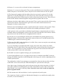
AR8000 bulletin page
Installing the DS8000 Speech Inversion Decoder
The DS8000 may be fitted to the AR8000 (also the AR5000) to provide analogue speech
inversion descrambling, however not all types of speech inversion can be addressed by this
option, primarily it is intended for Japanese cordless phones and some UK PMR446
transmissions etc.
The DS8000 fitting & operating instruction sheet for the AR8000 is presented here in an
Acrobat PDF file format, the file is 50kB in size.
For operation of the DS8000 with the AR5000, please refer to the AR5000 operating manual.
AR8000 Discriminator Output
The discriminator output on the AR8000 is taken from pin 11 on U1. U1 is a TK10489 on the
middle IF board.
To get to the correct board first split the set by removing the screws in the battery
compartment and at the top of the set. The set is then split in two main pieces. The board that
the discriminator output is on the board in the rear half of the set. This is the IF board and
needs to be removed.
To remove the IF board unscrew the nuts off each encoder on the top of the set. Next remove
the two screw in the bottom of the board, and make sure the battery terminals that come
through the board are straight. Gently ease the board away from the rear of the set.
U1 is located on the rear of the board that has just been removed. The discriminator output is
taken from pin 11 of the TK10489 and a suitable earth.
Opto Scout Modification
The hardware modification includes adding a small jack to the radio to make it possible to
connect the Scout™ with a flexible cable using 2.5mm phone jacks cables, and plugs. The
modification described will permit easy connection from the Scout™ to the radio for reaction
tune operation. This modification may however void the manufacture's warranty. Keep this in
mind and make sure you are aware of the possibility.
Having been warned, it can be stated that the addition of the jack described here as easily
done by a qualified electronics technician who is experience in working on two way radios
and scanners. Careful soldering of the wires to locations is necessary. If you are not
experienced at soldering or taking apart hand held radios you should seek assistance from a
qualified technician.
Disassemble the radio and check the jack location against the picture. Make sure all the
batteries are removed and that the power adapter is disconnected.
The jack being installed is a 2.5mm (3/32") phone jack. The centre or tip connection from the
Scout carries data to the radio. The wires used are number 24 stranded. In the AR8000, the
wire lengths are short, a little more than an inch.
It is not necessary to drill a hole for the jack. locate the position of the hole relative to the
power jack as shown in the picture. Tale a few minutes to see that the jack location will not
interfere with the PC boards when the radio is re-assembled. To create a hole in the plastic
case , use an X-acto knife and place the point in the centre of the desired location. Rotate the
blade creating a hole in the soft plastic. Keep checking the hole size against the jack to make
sure that you don't make it too large. It may be necessary to bevel the edge of the hole for the
nut to fit on the jack. Some people feel that it is easier to create the hole in this manner than to
use a drill (if a small drill is available, it becomes a simple operation but hold some protective
material such as a wood block inside the cabinet of the AR8000 to prevent the drill from
raking all the components from the inside of the radio!
The ground connections can be made where ever it is convenient. The picture shown positions
that work well. The data connection in the AR8000 is taken directly from a chip resistor (as
shown). Solder carefully to prevent damage to the resistor. Check for continuity between the
nut on the outside of the jack and the ground connection to the radio's PC Board using a
tester. If this checks out and polarity is not reversed then re-assemble the radio.
Power up: When the Scout is twitched on, a display self test is performed. The self-test
consists of illuminating all front panel display segments and annunciators for approximately
two seconds, followed by displaying 'SCOUT' for another two seconds and then the
communications LANGUAGE enabled for another two seconds. The Scout then begins
operation in the operating mode selected by the FILTER and CAPTURE switches (AOR
AR8000 or CI-V ICOM).
Changing the position of the CAPTURE switch during the display self text will toggle the
serial communications language between CI-V and AR8000. The default communications is
9600bps, experiment with CR/LF or place the AR8000 into NEW_USER_MODE, the
parameters will then be correct! Place the AR8000 in 2VFO mode, remember, reaction-tune
will only occur when active new frequencies are clocked by the Scout. When new
transmissions are encountered, the AR8000 will react and follow the display of the Scout
immediately, after a period of monitoring recall the SCOUT MEMORIES to select which
frequencies you wish to store into the AR8000.
AR8000 Keypad Replacement
The AR8000 keypad comprises of a complete membrane with carbon printed contacts.
Eventually with use, the carbon will deplete resulting in failure. There were two types of
replacement keypad as spare parts, standard (original) and 'hard shell' (later)... the 'hard'
type has a cover over the printed letters to prevent them from wearing off.
A new keypad has been introduced in 2003 to replace BOTH types of keypad. The part
number is:
Standard
A few customers have commented on slight difficulty when fitting the later types of keypad
on earlier sets and feel that the later keypad may be very slightly larger (the front case holes
of the later sets providing greater clearance) so have had to carefully enlarge the clearance
with glass-paper etc.
Before any work is carried out, place the set on a bench covered with a duster to prevent the
set being scratched.
1) Remove 2 x screws (silver coloured) in battery compartment.
2) Remove 2 x screws on side panels. These are the small black screws located next to the
rubber side pieces. On each side, remove only the screw located nearest to the rear panel.
3) The front panel complete with the rubber side pieces can now be removed. To do this,
slight force is needed pulling the two case halves away from each other. Do not lever the
halves apart and do not twist them apart as inside connector pins may be bent.
4) With the front case half removed, the main circuit board now has to be removed from it in
order to expose the keypad.
To do this, remove 5 screws (silver coloured) holding the board in place and unclip the
speaker connector.
5) Carefully lift the board away from the case noting that the side switch panel will also lift
away with the main board (there is no need to separate the two).
6) The keypad can now be lifted out of the case.
If any contamination has been deposited onto the board contacts, this can be cleaned away by
light rubbing with a non residue solvent and cloth.
Refitting is the reverse of the above procedure. Care must be taken to ensure that the new
keypad is situated the correct way up and with all its keys located in their slots in the case
front before refitting the board. Care must also be taken to make sure that when mating the
two halves together again, all of the connector pins locate correctly. It the two halves are
pressed directly together keeping both sides parallel, then no problems should arise.
Do nut over tighten any of the screws.
Power up the set and check the operation of all the keys.
Wandering "Birdies"
The floating birdies appear to be an interaction between the two DC-DC inverters of the I.F.
PCB and ceramic crystal of the CPU PCB. When the set is fully assembled, both boards come
close together and probably interact.
The frequency of the CPU crystal is 4.91MHz, it is easy to locate the crystal on the CPU PCB.
Simply remove the two screws in the battery compartment and the two (rear half) case screws
on the side of the receiver near to the top. The receiver will part into two... the crystal is on
the CPU half near the centre of the board. It is soldered directly to the PCB and looks very
similar to a miniature fuse.
This crystal may be replaced with a *metal cased* crystal package style HC49/4H being
recommended (half height)... a watch style crystal may be even better. Of course the legs
cannot pass through the PCB so lay the crystal on its side soldering the legs to the PCB crystal
pads keeping them as short as possible.
Any frequency above about 4.2 MHz will be okay (the pitch of the beep will change though)
but if you want to retain the REMOTE CONTROL / CLONE capability then you need to be
very close to 4.91 MHz: 4.9152 MHz is available as an "off the shelf" item from most good
component suppliers and retains the REMOTE CONTROL capability.
Tightening BNC socket and replacement of wire link
Before any work is carried out, place the set on a bench covered with a duster to prevent it
being scratched.
1) Remove 2 x screws (silver coloured) in battery compartment.
2) Remove 2 x screws on side panels. These are the small black screws located next to the
rubber side pieces. On each side, remove only the screw located nearest to the rear panel.
3) The front panel complete with the rubber side pieces can now be removed. To do this,
slight force is needed pulling the two case halves away from each other. Do not lever the
halves apart and do not twist them apart as inside connector pins may be bent. This will leave
the RF and IF boards connected together along with the top panel and rear case.
4) Remove the three rubber knobs on the top panel. These can be removed with a fairly strong
pull and twist motion. If the knobs have gone soft or the rubber inside them has been
damaged, it is best to replace them.
5) Remove the nuts holding the volume, squelch and encoder controls to the top panel. These
are not usually very tight and can be loosened with a suitably pointed pair of pliers.
At this point it is also a good idea to withdraw from the battery compartment the two battery
terminals which pass through the sockets on the IF board. Note that the ends of these contacts
may be bent over and will need to be straightened before removal.
6) Undo the two screws holding the PCB in place and withdraw the board from the set by
lifting the bottom of the board (to separate the connector between IF and RF boards) before
withdrawing the controls from the top panel.
7) The rear of the BNC socket should now be visible. Note; some sets may have an earth strap
which will have to be de-soldered.
If you are intending to just tighten the BNC socket, this can be done without any further
dismantling, but, it is much easier if the entire RF board is removed from the rear case (three
screws - two at rear and one in centre) and then the top panel removed from the RF board
(solder joints to BNC centre and earth points).
8) The BNC can now be tightened using a pair of pointed pliers.
It can be quite difficult to get it very tight, but one trick is to hold the actual BNC socket by
placing an old BNC plug onto it and holding that with a large pair of pliers, tightening the nut
with the pointed pliers.
The problem here is that if you manage to get enough force between the two pliers, the lugs
on the BNC can be sheered off (the AOR workshop has a special tool for this job).
Once tight, a spot of sealant can be used on the nut to keep the socket in position. A blob of
super-glue could be used although this can make it impossible to remove the socket in the
future should it ever require replacing. Note; do not use screw-lock, as this can make the
plastic top panel brittle.
9) If the antenna wire link was broken, it can be replaced easily at this point.
The original one fitted is a solid wire link threaded through a very small bead (usually white
in colour, it is not an inductor!).
A simple piece of wire soldered in place will replace this or, better still, add a small piece of
flexible wire to prevent any future breakage.
If you are careful, the small bead can be slid off the original wire and threaded onto the new
link (it usually has a spot of glue holding it on) although this is trickier than it sounds (and is
debatable if its omission makes any difference at all).
10) Rebuild the unit in reverse order to the above.
Don't forget to re-solder the BNC earth. Although this is slightly flexible, it is a good idea to
solder it once the RF board and top panel are refitted to the rear cover to get it in its correct
position.
Take care to put the control pots through the top panel before pushing the IF and RF board
connectors together. Similarly make sure that the front section and IF boards are positioned
correctly before pushing the sockets together.
It is a good idea to re-fit the battery terminals before the front panel is fitted. Bend over any
protruding wire from the back of the battery sockets with a pair of pliers - this will prevent the
battery terminals coming loose or dropping out.
Don't over tighten the control pot nuts and make sure that they are fairly central in their
recesses. The rubber knobs should just push on again.
11) Test your work.
EARLY AR8000 (first 500 units) CPU tolerance - won't always switch on
A 'few' reports have been received suggesting that the AR8000 will not always switch back on
again once switched off, especially when using NiCads. Sometimes the LCD lamps illuminate
and other times the set does nothing at all (occasionally just two lines of text are displayed at
boot-up).
This is a minor tolerance problem due to a high value resistor (1M OHM) in part of the reset
circuit. The problem is not that it won't switch on, but rather one inverter doesn't switch off !
The remedy is SIMPLE and involves the fitting of one diode such as a 1SS268 etc (since this
time fitted to all production units - from about serial 10500 upward).
1. Remove the battery cover & NiCads.
2. Remove the two screws in the battery compartment.
3. Remove the two side screws nearest the rear case... it is not necessary or advisable to
remove all four screws.
4. Carefully separate the two case halves.
5. Locate the 1M OHM surface mount resistor on the microprocessor PCB (R6). Fit a diode
across the 1M OHM resistor - it is easier to anchor between the regulator S-8054 (far right pin
with set upright) and C8. An 1SS268 diode is used simply because it is small and fits easily
but a standard 1N4048 or similar may be used to equal effect. If a 1SS268 is used (double
diode SMD package) then only one diode is used so one leg is unused.
6. Reassemble and test.
AR8000 BANDSCOPE bandwidths
The bandwidth is centre frequency (the frequency you are listening to) PLUS + MINUS five
divisions:
USB/LSB/CW
approx 3kHz per division regardless of step size, giving a maximum
bandwidth of about 28 - 30kHz.
approx 10kHz per division when step size is 12.5kHz or less
AM/NFM/WFM when step size is 25kHz or above, the bandwidth per division is equal to
the current step size i.e. 30kHz, 50kHz, 100kHz, 200kHz etc.
AR8000 'PLL ERR' display
If the 'PLL ERR' message is displayed when the batteries have only slightly discharged (the
receiver works okay from external supply), add a 10pF capacitor to the I.F. PCB in parallel
with R33, this should prevent the PLL unlock.
AR8000 low battery indication
Occasionally it is possible for the LOW BATTERY message to appear on the LCD
prematurly. The 'low battery' message should appear when the battery voltage typically drops
to 4.2V and the 'battery error' message is displayed when the voltage typically drops to 3.5V
(at which point the receiver stops functioning).
The low battery display is monitored by the CPU via a potential divider (pair of series
resistors) R25 (33k OHM) and R26 (100k OHM) on the CPU PCB. In incorrect results are
displayed, adjust the values of R25 & R26.
AR8000 squelch splutter (audio mute)
The squelch operation on the AR8000 is controlled by the squelch line entering the
microprocessor on pin 63. The audio mute is controlled by the microprocessor from pin 11.
There is very little time delay between the action of these two lines. The squelch signal
operates very quickly with respect to the RFinput into the receiver. Signals with levels close
to the threshold can therefore produce a broken recovered audio (audio mute).
On our demonstration set (early production), the squelch threthold was 0.2uV going to 50uV
fully clockwise making the squelch setting quite critical. A later production set had a far
narrower (better) range of 0.15uV to 1.5uV.
The mute delay time constant is controlled by R81 (100k OHM) and C96 (0.1uF) on the I.F.
board. It is also probably controlled by the microprocessor but the AOR UK workshop does
not have design data on this matter. Increasing the time constant of this circuit gives a far
'nicer' audio mute response (i.e. removes any squelch chopping in and out) but doesn't affect
the actual squelch performance with regard to signal, search and scan... there is a slihght side
effect of a very brief 'shhhh' noise at the end of transmissions prio to the squelch closing.
Just altering C96 to 2.2uF or 4.7uF (or even parallelling 1.0uF) gives a second or so delay
which appears to be plenty to remopve the squelch chattering on smaller signal lavels. The
actual squelch action with regard to RF performance is unaffected as only the audio mute had
been modified.
AR8000 squelch 'blindness'
It is possible for the AR8000 squelch to remain open irrespective of the controls position
(even fully clockwise) WITH NO SIGNAL PRESENT.
1. Place the receiver in [2VFO] mode.
2. Enter a VHF frequency into VFO 'A' such as 145.400MHz NFM. Ensure there is no
transmission.
3. Switch to VFO 'B' by pressing [2VFO].
4. Enter a frequency into VFO 'B' such as 5.505MHz USB. Ensure that the receiver is picking
up a signal (so that AGC is being produced).
5. Press [2VFO] to swap back to VFO 'A'. WHITE NOISE will be audible and cannot be
muted even with the squelch control fully clockwise.
6. The squelch will then close if:
a. if a good strong signal appears then departs
b. press the [MONI] key
c. rotate the tuning [DIAL]
d. re-enter the wanted frequency via the keypad
The above has been reproduced on ALL sets irrespective of serial number or production
batch, it must be considered as a 'characteristic'.
AR8000 locked out memory - VFO transfer CPU reset
There is a known situation in which the AR8000 can be made to reset. This will happen if you
press [A=B] to transfer a locked out memory channel to VFO. The receiver will appear to
function perfectly but will rest when next switched off / on again.
If you wish to transfer a PASS CHANNEL to VFO, use the [ENT] key to transfer the
frequency to the temporary VFO (rather than 2VFO) as described in the operating manual (or
unlock the locked out memory channel first).
AR8000 supplied aerial frequency response (RA8000)
A crude test carried out on the AR8000 antenna shows quite a large dip around the area of the
VHF marine band. Results were obtained by simply injecting a 0dBm signal into an (uncalibrated VHF) antenna approximately 2 metres away from the AR8000 antenna connected
to the 50OHM input of a spectrum analyser. Telescopic aerial provide far better results,
especially for marine monitoring but are less concealable and more prone to mechanical
damage.
AR8000 stuck on lower case memory banks
A few AR8000 operators have found that their sets have automatically reverted to LOWER
CASE memory channels when manually selecting memory locations. This has been found to
be the result of enabling select scan mode.
With one or more memory locations tagged for select scan, the AR8000 will automatically
select the CASE of memory location to be that of the first tagged location. Selection of the
other CASE memories is possible but has to be selected every time a location is entered. Any
subsequent tagged locations make no difference.
For example:
If memories a01 & A02 are tagged for select scan, then when manually selecting a memory
location, the set will automatically go to the lower case memories unless specifically
requested otherwise.
If memories a03 & A02 are tagged, the set will default to upper case locations in manual
select.
If however, the first tagged memory location in upper and lower CASE memories is the same
(i.e. a04 & A04), then the set will not automatically default to either case. Memory retrieval
will behave as if select scan is not enabled.
AR8000 computer port connection (ribbon cable)
EARLY AR8000 audio scan component change
On early production units (above 10500 but below 12000), the audio scan / audio search
facility may fail to stop on low-modulated signals such as 12.5kHz NFM transmissions.
This is likely to be due to a lowering of AF gain in NFM to reduce the possibility of
microphonic behaviour. This action has incidentally lowered the level of signal path to the
CPU which monitors whether the received signal is modulated or unmodulated.
To compensate for this change in level, the component values around U5(B) have been
changed:
Component Old
New
47k OHM 22k OHM
R82
R83
470k OHM 1M OHM
C98
220pF
100pF
This component change was applied to all later production units.
One possible side effect, when a tape recorder adapter (CR8000) is connected when receiving
a strong high level AM signal, some distortion may be experienced.
AR8000 narrow AM filter
Some time ago Lowe in the UK developed a modification for the AR8000 where the SSB
filter was switched in circuit for narrow-band AM reception (short wave)... the switching of
the optional DS8000 was utilised for standard / narrow filter selection. Following the arrival
of 'CE' emission standards, the modification was dropped several years ago. Their modified
AR8000 was marketed under the title of AR8000DX. More recently in the UK has been
offering narrow AM switching, the origins are thought to be the same design but AOR has no
specific information.
Other designs to switch the SSB filter for AM listening have been posted to the internet. The
following is an example and is not intended as a modification text, nor is it endorsed or tested
in any way:
No cuts to the pins or sockets are required. There are two etch runs near F3 and F4 along
with a couple of existing feed through holes. Make etch cuts and solder 'wire-wrap' wire to
the cut etch and then take advantage of the existing feed through holes to solder the wires to.
Break the two lines feeding the 12kHz filter (NFM) and 4.0kHz filter (SSB), switch with a
DPDT switch. When the DPDT switch is in one position everything is normal. When the
switch is in the other position, break the two etches and then send the voltage that normally
would turn on the 12kHz filter over to the 4.0kHz filter. It connects to the two (22k OHM)
resistors that feed two diodes which direct the path through both filters.
AR8000 RS232 signal level response
Using the LM command to the AR8000 through RS232 control a theoretical signal level
response can be obtained with up to 64 steps. In practice, the number of steps is little over 40.
The response levels may vary slightly from set to set but for each set, the level is very
consistent.
Levels taken from one of the later production units are as follows:
Input signal level dBm Hex response
-120
0
-116
05
-112
06
-111
07
-110
07
-109
08
-108
09
-107
0A
-106
0B
-105
0B
-104
0C
-103
0D
-102
0E
-101
0F
-100
10
-95
14
-90
17
-85
1A
-80
1C
-75
1E
-70
1F
-65
20
-60
22
-55
23
-50
23
-45
24
-40
25
-30
26
-10
27
+10
28
AR8000 top panel knobs
As time passes, the top panel knobs may appear to loosen, this is more apparent on earlier
units. Occasionally we receive reports that the on/off switch does not function... in reality the
knob is simply slipping round-and-round and no longer has enough friction to activate the
on/off click switch.
The knobs have a rubber type composition and appear to chemically react with the metallic
material of the control shafts over a period of time. The later AR8000 knobs have a harder
composition and thicker walls, in fact it is quite difficult to pull the later type knobs off the
control shafts, a grip like superman is required!
When replacing the top panel knobs, clean the shaft with a cloth or tissue to remove any
residue before fitting the replacement knob. It is common to find a green fluid present on the
control shafts.
Replacement knobs are available as spare parts, please refer top the Service section of the
AOR UK web site. These spare parts are relatively inexpensive.
Remember, the Vol/On/Off and Squelch knobs have 'dots' printed on them while the encoder
knob is blank.
AR8000 Battery contact springs
The two battery contacts in the top right and left hand corners of the AR8000 provide the
battery feed through the case to the main PCBs. They pass through small holes in the case
and locate into sprung sockets fitted to the PCB. This provides a versatile method of
connection and allows battery contacts to be replaced without the need for removing any case
parts - but it has its drawbacks.
The battery contacts may come out with the batteries when they are removed (especially if
the batteries are a tight fit). This is no problem if the board socket remains in place when the
contact is pushed back into place, but the sockets can also be pushed away from their location
when re-inserting the contact.
Later sets overcame these problems by bending the end of the battery contacts over slightly
after the wire end had passed through the socket. This was done before final assembly. These
battery contacts cannot be removed without removing the case but also do not come out
accidentally.
To replace or re-fit the battery contacts:
Remove the battery cover and batteries.
Remove the two screws in the battery compartment.
Remove one screw from each side panel on either side of the radio (it’s probably best to
choose the screws nearest the rear panel).
The two case halves should now pull apart. Note that a small amount of resistance will be
experienced as the two inter-board sockets are being pulled apart.
The battery contacts and their sockets are now exposed on the middle PCB.
If the battery contacts are bent over, straighten them with a pair of pliers before pulling them
out through the battery compartment.
If the battery contacts are already out, check that the sockets are straight and upright on the
PCB to allow the contacts to be re-fitted.
If the set has had a hard life, check that the metal section of the socket is still springy and
making a good connection with the battery contact. With the battery contact removed, the
socket contact should return to the same position as the two unused sections of the socket next
to it. I.e. the gap where the battery contact has pulled out from should close up.
If worn, it is possible to replace it with one of the unused sections of the socket.
Briefly how to do this –
Remove the three control knobs.
Remove the three lock nuts (fine pliers should do).
Unscrew the two board screws.
Remove the board.
Unsolder the offending socket.
If removing both sockets, simply re-fit each socket in the others position (hence an unused
section now becomes a used section).
If only removing one socket, the spring contacts can be removed and exchanged - Click the
solder end out of the socket and bend up slightly, press the lug hidden underneath and
withdraw the contact. Exchange it with one of the unused ones and refit.
Re-assemble in reverse to the above (note; new control knobs may have to be fitted).
Re-fit the battery contacts through the holes in the battery compartment and into the sockets.
Using a pair of pliers, bend over the protruding end of the contact slightly to prevent it
coming out again. This may not be possible if the contacts are very short. If this is the case,
before pushing them fully home, put a small amount of glue (‘super-glue’ will do) on the
section of the contact to be pushed into the case hole and/or side slots.
Re-assembly is the reverse of the above procedure.
Take care that the two inter-board contacts fit together correctly and that the side panels fit
into their slots.
Now refit your batteries and test your work.
Additional note:
Three other battery contacts are fitted to the set. These are a ‘double’ contact items and are
located by a slot at each end and three plastic lugs moulded into the case. These do not
generally cause any problems but on later sets have a spot of glue in the slots and on the lugs
to add to their robustness. It is a good idea to carry this out at the same time with the aid of a
tube of ‘super-glue’. Take care to keep the glue away from the spiral section which makes
contact with the battery – ‘super-glue’ makes quite a reasonable insulator.
AR8000 DC socket replacement
A 1.3mm concentric power socket is fitted to the AR8000. Although reasonably robust, it is
only a small socket and may eventually fail after several years of hard use. Alternatively with
rough use or a lot of movement when connected to an external power source, the solder
connections may eventually break.
Either of these problems are easily rectified by someone reasonably competent with a small
soldering iron.
At worse a new socket will have to be purchased and possibly a new set of control knobs.
These are all relatively low cost items and are usually available from stock.
To carry out the work:
Remove the battery cover and batteries.
Remove the two screws in the battery compartment.
Remove one screw from each side panel on either side of the radio (it’s probably best to
choose the screws nearest the rear panel).
The two case halves should now pull apart. Note that a small amount of resistance will be
experienced as the two inter-board sockets are being pulled apart.
The CPU / display board remains attached to the front and top panel, rear (RF/VCO) and
centre (IF) boards remain attached to the rear panel.
The power socket is now visible on the centre PCB.
The battery contacts and their sockets are also now exposed. If the battery contacts are bent
over, straighten them with a pair of pliers before pulling them out through the battery
compartment.
If the battery contacts are already out, check that the sockets are straight and upright on the
PCB to allow the contacts to be re-fitted.
Remove the three control knobs. These should just pull off, although they can be very stiff. If
old, worn or gone soft, it is a good idea to use this as an opportunity to replace them. If
replacing them, remove any traces of oil from the shafts. Some sets also had a green sealant
on the shafts. Remove any traces of this. Note; leave re-fitting of the knobs until the very last
job after testing the radio. Having to remove them again may damage them.
Remove the three lock nuts now revealed (a pair fine pointed pliers will do this if care is
taken).
Remove the two board screws.
Lift the centre PCB straight away from the rear panel and then withdraw the control pots from
the top panel. Again, resistance will be experienced due to a connector in the centre of the
board.
With the underside of the board now exposed, the power socket can de-soldered and removed
or simply re-soldered if the joints have fractured.
When refitting, for additional robustness, a small amount of solder can also be applied to the
two exposed parts on the upper side of the socket.
If the PCB solder pads have fractured or lifted from the board. The only option is to bridge the
broken section with a small length of suitable wire. Luckily all PCB tracks going to the socket
connections are clearly visible, so this should present too many problems.
Although I’ve never done it, a spot of glue on the underside of the power socket will add to its
robustness – this could also hold the socket in place while it is being soldered.
Re-assembly is the reverse of the above procedure. Take care when fitting the boards together
to ensure that inter-board sockets are mated together correctly.
Refit the battery contacts before the cases are joined and bend the protruding end of the wire
over to prevent the battery contact from being able to come out again accidentally.
When fully assembled but before fitting the control knobs, connect the power supply and test
your work. Also check battery operation.
Many thanks fort the Infos to www.aoruk.com