1
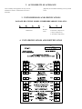
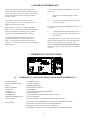
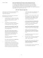
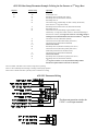
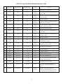
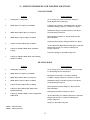
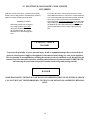
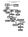
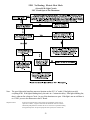
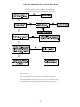
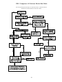
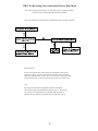
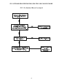
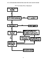
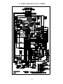
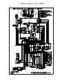
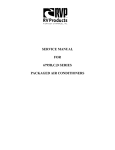
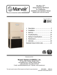
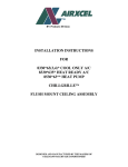
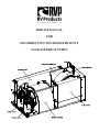
SERVICE MANUAL
FOR
6535 SERIES TWO TON HIGH EFFICIENCY
PACKAGED HEAT PUMPS
TABLE OF CONTENTS
1.
2.
3.
4.
5.
6.
7.
8.
9.
10.
11.
12.
13.
14.
Warnings . . . . . . . . . . . . . . . . . . . . . . . . . . . . . . . . . . . . . . . . . . . . . . . . . . . . . . . . . . . . . . . . . . . . . . . . . . . . . . . . . . 2
Accessibility Of Appliance . . . . . . . . . . . . . . . . . . . . . . . . . . . . . . . . . . . . . . . . . . . . . . . . . . . . . . . . . . . . . . . . . . . 3
Unit Dimensions And Specifications . . . . . . . . . . . . . . . . . . . . . . . . . . . . . . . . . . . . . . . . . . . . . . . . . . . . . . . . . . 3
Unit Specifications And Identification . . . . . . . . . . . . . . . . . . . . . . . . . . . . . . . . . . . . . . . . . . . . . . . . . . . . . . . . . 3
Unit Depiction Figures . . . . . . . . . . . . . . . . . . . . . . . . . . . . . . . . . . . . . . . . . . . . . . . . . . . . . . . . . . . . . . . . . . . . . . 4
General Information . . . . . . . . . . . . . . . . . . . . . . . . . . . . . . . . . . . . . . . . . . . . . . . . . . . . . . . . . . . . . . . . . . . . . . . . 5
Thermostat Specifications . . . . . . . . . . . . . . . . . . . . . . . . . . . . . . . . . . . . . . . . . . . . . . . . . . . . . . . . . . . . . . . . . . . 5
A. 6535-3451 Coleman-mach Series Thermostat . . . . . . . . . . . . . . . . . . . . . . . . . . . . . . . . . . . . . . . . . . . . . . . . 5
B. 6535-3351 Coleman-mach Series Thermostat . . . . . . . . . . . . . . . . . . . . . . . . . . . . . . . . . . . . . . . . . . . . . . . . 7
Heat Pump Operation Sequence Cooling Mode . . . . . . . . . . . . . . . . . . . . . . . . . . . . . . . . . . . . . . . . . . . . . . . . 10
Heat Pump Operation Sequence Heating Mode . . . . . . . . . . . . . . . . . . . . . . . . . . . . . . . . . . . . . . . . . . . . . . . . 10
Wirebox Component Checkout
A. Wirebox Component Checkout 6535 (-) Series . . . . . . . . . . . . . . . . . . . . . . . . . . . . . . . . . . . . . . . . . . . . . . . 11
B. Wirebox Component Checkout 6535 (A) Series . . . . . . . . . . . . . . . . . . . . . . . . . . . . . . . . . . . . . . . . . . . . . . 12
Service Problems And Possible Solutions . . . . . . . . . . . . . . . . . . . . . . . . . . . . . . . . . . . . . . . . . . . . . . . . . . . . . 13
Electrical Diagnostic Flow Charts . . . . . . . . . . . . . . . . . . . . . . . . . . . . . . . . . . . . . . . . . . . . . . . . . . . . . . . . . . . . 14
A. Cooling Mode Operation . . . . . . . . . . . . . . . . . . . . . . . . . . . . . . . . . . . . . . . . . . . . . . . . . . . . . . . . . . . . . . . . 15
A.1 No Cooling; Cooling Mode (Green L.E.D. Light Circuit) . . . . . . . . . . . . . . . . . . . . . . . . . . . . . 16
A.2 No Indoor Blower Low Speed; Cooling Mode . . . . . . . . . . . . . . . . . . . . . . . . . . . . . . . . . . . . . . . 17
A.3 No Indoor Blower High Speed; Cooling Mode . . . . . . . . . . . . . . . . . . . . . . . . . . . . . . . . . . . . . . 18
A.4 Compressor #1 Checkout; Cooling Mode . . . . . . . . . . . . . . . . . . . . . . . . . . . . . . . . . . . . . . . . . . 19
A.5 Compressor #2 Checkout; Cooling Mode . . . . . . . . . . . . . . . . . . . . . . . . . . . . . . . . . . . . . . . . . . 20
B. Heating Mode Operation . . . . . . . . . . . . . . . . . . . . . . . . . . . . . . . . . . . . . . . . . . . . . . . . . . . . . . . . . . . . . . . . 21
B.1 No Heating; Electric Heat Mode (Green L.E.D. Light Circuit) . . . . . . . . . . . . . . . . . . . . . . . . 22
B.2 No Indoor Blower; Electric Heat Mode . . . . . . . . . . . . . . . . . . . . . . . . . . . . . . . . . . . . . . . . . . . . 23
B.3 Compressor #1 Checkout; Electric Heat Mode . . . . . . . . . . . . . . . . . . . . . . . . . . . . . . . . . . . . . 24
B.4 Compressor #2 Checkout; Electric Heat Mode . . . . . . . . . . . . . . . . . . . . . . . . . . . . . . . . . . . . . 25
B.5 No Reversing Valve Operation Electric Heat Mode . . . . . . . . . . . . . . . . . . . . . . . . . . . . . . . . . . 26
C. Outdoor Blower Motor; Heating or Cooling Mode
C.1 No Outdoor Blower Low Speed . . . . . . . . . . . . . . . . . . . . . . . . . . . . . . . . . . . . . . . . . . . . . . . . . . . 27
C.2 No Outdoor Blower High Speed . . . . . . . . . . . . . . . . . . . . . . . . . . . . . . . . . . . . . . . . . . . . . . . . . . 28
Wiring Diagram - 6535 (-) Series . . . . . . . . . . . . . . . . . . . . . . . . . . . . . . . . . . . . . . . . . . . . . . . . . . . . . . . . . . . . 29
Wiring Diagram - 6535 (A) Series . . . . . . . . . . . . . . . . . . . . . . . . . . . . . . . . . . . . . . . . . . . . . . . . . . . . . . . . . . . . 30
1. WARNINGS
IMPORTANT NOTICE
BREAKER FOR THE AIR CONDITIONER TO OFF,
DISCONNECTING ALL EXTERNAL ELECTRICAL
CONNECTIONS AND CORDS, SWITCHING ON BOARD
ELECTRICAL GENERATORS AND INVERTOR TO OFF, AND
REMOVING THE CABLE FROM EACH POSITIVE TERMINAL
ON ALL STORAGE AND STARTING BATTERIES.
These instructions are for the use of qualified individuals
specially trained and experienced in installation of this type
equipment and related system components.
Installation and service personnel are required by some states
to be licensed. PERSONS NOT QUALIFIED SHALL NOT
INSTALL NOR SERVICE THIS EQUIPMENT.
CAREFULLY FOLLOW ALL INSTRUCTIONS AND
WARNINGS IN THIS BOOKLET TO AVOID DAMAGE TO
THE EQUIPMENT, PERSONAL INJURY OR FIRE.
SHOCK HAZARD
WARNING
TO PREVENT THE POSSIBILITY OF SEVERE PERSONAL
INJURY, DEATH, OR EQUIPMENT DAMAGE DUE TO
ELECTRICAL SHOCK, ALWAYS BE SURE THE POWER
SUPPLY TO THE APPLIANCE IS DISCONNECTED BEFORE
DOING ANY WORK ON THE APPLIANCE. THIS CAN
NORMALLY BE ACCOMPLISHED BY SWITCHING THE
Improper installation may damage equipment, can create a
hazard and will void the warranty.
The use of components not tested in combination with these
units will void the warranty, may make the equipment in
violation of state codes, may create a hazard and may ruin the
equipment.
2
2. ACCESSIBILITY OF APPLIANCE
The accessibility of this appliance will vary from one
installation to another. It shall be left to the service
technicians.
judgement, the best method of attaining access to perform
service.
3. UNIT DIMENSIONS AND SPECIFICATIONS
PACKAGE HEAT PUMP MODEL NUMBER BREAKDOWN FOLLOWS:
6
5
3
5
Revision
Letter
Model Series
X
7
1
6 - Panasonic Compressor(s)
7 - Sanyo Compressor(s)
8 - Tecumseh Compressor(s)
4. UNIT SPECIFICATIONS AND IDENTIFICATION
3
5. UNIT DEPICTION FIGURES
Figure 1
Figure 2
4
6. GENERAL INFORMATION
This packaged heat pump mounts below the floor of the
vehicle. The innovative design makes it possible to maintain a
smooth, free-flowing roof line for the vehicle. It also relocates
all noise and condensate drainage off the roof to below the
floor of the vehicle.
1st stage (the first compressor and refrigeration circuit), will
operate when:
1)
The thermostat is demanding cooling or electric
heating,
The heat pump contains a dual compressor system. It
combines the capacity of two roof mounted units into one
highly efficient and compact package.
2)
The vehicle is being powered by either shore line or
the on-board generator.
2nd stage (the second compressor and refrigeration circuit), will
operate when:
Each compressor is connected to a separate refrigeration
circuit. The system can be operated with a single compressor
when the air conditioning requirement is low, or with two
compressors when maximum performance is required.
1)
This heat pump operates a two-stage system. The first
compressor and refrigeration circuit is referred to as “1st
Stage”. The second compressor and refrigeration circuit is
referred to as “2nd Stage”. First and second stage will operate
as indicated below.
The thermostat senses room temperature that is 2
degrees or higher than the setpoint temperature on
the thermostat.
Switching and control of 1st and 2nd stage cooling is automatic.
When the cooling demand does not require that both systems
operate, stage two will shut down leaving stage one in
operation. Heat operation always energizes both stages,
however, only stage one operates if power is not available to
circuit #2.
7. THERMOSTAT SPECIFICATIONS
7A.
THERMOSTAT - 6535-3451 COLEMAN-MACH SERIES THERMOSTAT
SET TEMP. RANGE:
DISPLAY TEMPERATURE:
SCALE:
DISPLAY FORMAT:
RESOLUTION:
ACCURACY:
SAMPLING RATE:
POWER SOURCE:
OPERATING TEMPERATURE:
OUTPUT LOAD:
55 TO 90 DEGREES F.
-20 TO 160 DEGREES F.
DEGREES FAHRENHEIT
LIQUID CRYSTAL DISPLAY
ONE DEGREE F.
± 2% OF DISPLAY TEMPERATURE RANGE
EVERY 30 SECONDS
12 VDC NON-REGULATED, NON-FILTERED ± 2 VOLTS
-10 TO +55 DEGREE C.
40 mA MINIMUM TO 1.5 AMP MAXIMUM FOR EACH OUTPUT
SAFEGUARDS:
STATIC ELECTRICITY PROTECTION TO END USER AFTER INSTALLATION
ANTI-STATIC PACKAGING TO BE USED FOR SHIPMENT
SPIKE PROTECTION TO 400 VDC ON R+ TERMINAL
CONFORMAL COATING ON P.C. BOARD PROTECTION FROM MOISTURE
5
DEFAULT MODE:
WHEN THE THERMOSTAT IS SWITCHED TO HEAT AND ELECTRIC HEAT IS
SELECTED ON THE SUB-BASE, AND THE OUTDOOR TEMPERATURE FALLS
TO A POINT AT WHICH THE HEAT PUMP SHUTS DOWN (USUALLY BETWEEN
25 - 40 DEGREES), THE SUB-BASE WILL AUTOMATICALLY ALSO CALL FOR GAS
FURNACE OPERATION IF THE INDOOR TEMPERATURE DROPS TO 45 DEGREES.
GAS FURNACE OPERATION WILL SHUT OFF AT 60 DEGREES. THE USER SHOULD SWITCH
THE SUB-BASE TO GAS HEAT IF THIS OCCURS.
6535-3451 Thermostat Operation
The heat pump is operated from the wall mounted thermostat.
This thermostat will also operate the 12VDC furnace
connected to this thermostat.
no effect on the operation of the cooling blower. Fan
switch positions and their resulting function are
listed below:
Identification and operational descriptions for all thermostat
switches and display are listed below:
HIGH AUTO - When in the high automatic position,
the cooling blower operates at high speed and cycles
off and on with the 1st stage compressor. 2nd stage
cooling will cycle on and off as needed having no
effect on cooling blower operation.
1.
2.
Liquid Crystal Display - The display will be visible
any time the system is in operation. The display will
remain visible while the thermostat is on and
powered.
LOW AUTO - When in the low automatic position,
the cooling blower operates at low speed and cycles
off and on with the 1st stage compressor. 2nd stage
cooling will cycle on and off as needed having no
effect on cooling blower operation.
System Switch - The system switch has four
positions to control the operation of the heating and
air conditioning systems. They are as follows:
COOL - When in the cool position, 1st and 2nd stage
cooling will cycle from the cooling system setpoint.
Blower operation will be controlled by the position
of the Cooling Fan Switch.
LOW ON - When in the low on position, the cooling
blower operates continuously at low speed. Stage 1
and Stage 2 compressors cycle on and off as needed.
HIGH ON - When in the high on position, the
cooling blower operates continuously at high speed.
Stage 1 and Stage 2 compressors cycle on and off as
needed.
HEAT - When in the heat position, the heating
system will cycle from the heating system setpoint.
Heat will be by electricity (heat pump) or gas as
selected on sub-base. The gas heating blower will
operate per the heating system manufacturer
specifications.
During heat pump operation, the blower operates at
high speed with heat demand.
OFF - When in the off position, no thermostat or
system operation will occur.
4.
FAN - When in the fan position, the cooling blower
will operate continuously at high speed.
3.
Heat Source Switch - The heat source switch has two
positions to control the operation of the heating
systems. They are as follows:
ELECTRIC - When in the electric heat position, the
heat pump will cycle from the heating system
setpoint. Gas heat default is as described above in
the thermostat specifications
Cooling Fan Switch - The fan switch has four
positions from which to control the operation of the
cooling blower. The fan switch controls operation of
the cooling blower only after the system switch is
placed into the COOL position. With the system
switch in any other position, the fan switch will have
GAS - When in the gas heat position, the furnace will
cycle from the heating system setpoint.
6
6535-3451 Thermostat Wiring
The thermostat operation switches the
12VDC + to all output terminals
7B. THERMOSTAT - 6535-3351 COLEMAN-MACH SERIES THERMOSTAT
6335-3351 THERMOSTAT OPERATION
The display indicates room temperature and the word ROOM
is shown on the LCD until the temperature selector is pressed;
at which time the display temporarily indicates the setpoint
temperature and the word SET is shown on the LCD. Each
time the UP arrow is pressed, the setpoint will increase. Each
time the DOWN arrow is pressed, the setpoint will decrease.
Once the temperature selector button is no longer pressed for
a few seconds, the room temperature will again be displayed,
and the word ROOM will be displayed on the LCD.
In gas heat mode, the gas furnace will provide the only source
of heat and the heat pump is locked out.
NOTE
The temperature displays in degrees Fahrenheit
as a factory set default (See Figure 2). To
display in degrees Celsius, move the jumper
marked “F” and “C” to bridge between middle
pin and position “C”.
In electric heat mode, if the heat pump is unable to satisfy the
thermostat, DIFF will flash on the thermostat LCD when 2nd
stage heating is required to satisfy the thermostat.
7
6535-3351 Heat Pump Thermostat Example To Bring On Gas Furnace as 2nd Stage Heat
Setpoint
70
\\\
Indoor Temp.
70+
69
71
69
65
71
69
65
71
69
71
\\\
69
65
71
\\\
69
71
Operation
No functions occur
Heat Pump turns on (Primary heat source)
Heat Pump turns off (Thermostat satisfied)
Heat Pump turns on
Gas Furnace turns on (Heat Pump not able to satisfy Thermostat)
(First strike for 2nd stage heat counter)
Heat Pump and Gas Furnace turn off (Thermostat satisfied)
Heat Pump turns on
Gas Furnace turns on (Heat Pump is again unable to satisfy
Thermostat), (2nd stage heat counter reaches 3rd strike and Heat Pump is
locked out for 2 hours), 2nd stage heat counter is reset if Heat Pump is
running for more than 20 minutes and does not call for 2nd stage heat
Gas Furnace turn off (Thermostat satisfied)
Gas Furnace turns on (Becomes Primary heat source)
Gas Furnace turns off (Thermostat Satisfied)
After 2 hour lockout
Heat Pump turns on (Resumes as Primary heat source)
Gas Furnace turns on (Becomes primary heat source)
(Heat Pump is locked out for another 2 hours)
Gas Furnace turns off (Thermostat Satisfied)
After 2 hour lockout
Heat Pump turns on (Resumes as primary heat source)
Heat Pump turns off (Thermostat satisfied)
(2nd stage heat counter is reset any time Heat Pump satisfies
thermostat setpoint and does not need Gas Furnace)
The word “DIFF” will flash on LCD when 2nd stage heat is operating.
There is a 30 second delay between Stage 1 and Stage 2. Heat pump operation.
There is also a 3 minute anti-short cycle delay time of 3 minutes for cooling.
6535-3351 Thermostat Wiring
The thermostat operation switches the
12VDC + to all output terminals.
8
6535-335 2-stage Heat Pump Thermostat Operation Table
Mode Switch
Fan Mode Switch
Fan Speed Switch
Calling
1
Cool
Auto
Lo
No
2
Cool
Auto
Lo
Stage 1
1° Above Set
ID fan low, compressor #1 and OD blower low
cycle as needed
3
Cool
Auto
Lo
Stage 2
2° Above Set
ID fan low, compressors #1 & #2 and OD blower
high cycle as needed
4
Cool
On
Lo
No
5
Cool
On
Lo
Stage 1
1° Above Set
ID fan low continuous, compressor #1 and OD
blower low cycle as needed
6
Cool
On
Lo
Stage 2
2° Above Set
ID fan low continuous, compressors #1 & #2 and
OD blower high cycle as needed
7
Cool
Auto
Hi
No
8
Cool
Auto
Hi
Stage 1
1°Above Set
ID fan high, compressor #1 and OD blower low
cycle as needed
9
Cool
Auto
Hi
Stage 2
2° Above Set
ID fan high, compressors #1 & #2 and OD blower
high cycle as needed
10
Cool
On
Hi
No
11
Cool
On
Hi
Stage 1
1° Above Set
ID fan high continuous, compressor #1 and OD
blower low cycle as needed
12
Cool
On
Hi
Stage 2
2° Above Set
ID fan high continuous, compressors #1 & #2 and
OD blower high cycle as needed
13
Off
Auto
Lo or Hi
No
No functions occur in this mode
14
Off
On
Lo
No
ID fan low continuous
15
Off
On
Hi
No
ID fan high continuous
16
Gas Heat
Auto or On
Lo or Hi
No
No functions occur in this mode
17
Gas Heat
Auto or On
Lo or Hi
Stage 1
Heater will be energized to run
18
Gas Heat
Auto or On
Lo or Hi
Stage 2
There is no provision for 2nd stage heat when
operating in the gas heat mode
19
Elec Heat
Auto or On
Lo or Hi
No
20
Elec Heat
Auto or On
Lo or Hi
Stage 1
Heat pump will run ID fan high, both
compressors, OD fan high and both reversing
valves
21
Elec Heat
Auto or On
Lo or Hi
Stage 2
*See Note*
Heat pump will run ID fan high, both
compressors, OD fan high and both reversing
valves plus the heater will be energized to run
9
Operation
No functions occur in this mode
ID fan low continuous
No functions occur in this mode
ID fan high continuous
No functions occur in this mode
8. A TYPICAL COOLING CYCLE OF THE HEAT PUMP
Begins with a call from the wall thermostat for High or Low fan
(customer choice).
Compressor 2 starts, the outdoor fan goes off (subject to
available 115 volt power supply).
Indoor fan starts on the selected speed.
Outdoor fan starts again 2 seconds later (High Speed).
Within a few seconds the thermostat will call for cooling.
Both systems operate to satisfy the thermostat.
Compressor 1 starts.
Both compressors shut off at setpoint temperature.
Outdoor fan starts 2 seconds later (Low Speed).
When the thermostat calls for cooling again it will start by
calling for stage one only.
1 minute later the thermostat calls for second stage cool
(subject to 2 degree temp. differential).
If the heat pump is unable to keep up with the load, stage 2 will
start again when the indoor temperature is 2 degrees above the
setpoint.
9. A TYPICAL HEATING CYCLE OF THE HEAT PUMP
(Electric Heat Mode)
Begins with a call from the wall thermostat for Electric Heat.
Both systems operate to satisfy the thermostat.
Indoor fan starts on High Speed.
Both compressors shut off at set point temperature.
Both reversing valves switch to heat mode.
If the Heat Pump is unable to maintain the coach temperature,
the thermostat will automatically cycle the furnace on. The
new True-Air Thermostats (Electric Heat Mode) will call for
second stage (Furnace) heating operation anytime the
temperature inside the coach is more than 5 degrees cooler
than the customers chosen setpoint temperature. It is entirely
possible the furnace and the heat pump may both operate at
the same time to satisfy the thermostat.
Compressor 1 starts.
Outdoor fan starts 2 seconds later (Low Speed).
30 seconds later the Heat Pump circuit board will energize the
Compressor Relay #2.
Compressor 2 starts, the outdoor fan goes off (subject to
available 115 volt power supply).
Outdoor fan starts again 2 seconds later (High Speed).
10
10A. WIREBOX COMPONENT CHECKOUT
6535 “-” Model Unit
Note: The drawing above depicts a typical control box for the 6535 “-” Model Heat Pump only.
Heat Pump control boxes beginning with the “A” model do not have a high pressure switch.
The Heat Pump Printed Circuit Board has changed from time to time, the terminal designations and
board components as noted above may have changed locations on the board. Use the above drawing
only as a reference.
11
10B.
WIREBOX COMPONENT CHECKOUT
6535 “A” Model Printed Circuit Board
12
11. SERVICE PROBLEMS AND POSSIBLE SOLUTIONS
COOLING MODE
Problems
Possible Solutions
1.
Nothing Runs - Cooling Mode
No A/C Voltage, No 12 VDC, Thermostat, Wiring, P.C.
Board, High Pressure Switch Open
2.
IDFM* Runs, No Compressor, No ODFM*
Cooling Freeze Thermister - (Insufficient Indoor Air Flow),
Thermostat, Wiring, Compressor, Contactor, P.C. Board
3.
IDFM* Runs, ODFM* Runs, No Compressor
Insufficient Voltage To Unit, Run Capacitor, Start Device,
Overload, Wiring, Compressor
4.
IDFM* Runs, Compressor Runs, No ODFM*
Run Capacitor, Fan Motor, P.C. Board, Wiring, Fuse On
Motor Black Wire
5.
Compressor Runs, ODFM* Runs, No IDFM*
Thermostat, Run Capacitor, Wiring, Fan Motor, P.C. Board,
6.
Air Flow Restriction, High Ambient Temperature, Undersized
Refrigeration System, Very Little Or No Refrigerant
Charge, Compressor
Compressor, ODFM*, IDFM* Runs, Insufficient
Cooling
Thermostat, Wiring, P.C. Board, Reversing Valve
7.
Compressor, ODFM*, IDFM* Runs, Unit Is Heating
While In Cool Mode
HEATING MODE
Problems
1.
Nothing Runs - Heat Mode
2.
IDFM* Runs, No Compressor, No ODFM*
3.
IDFM* Runs, ODFM* Runs, No Compressor
4.
IDFM* Runs, Compressor Runs, No ODFM*
5.
Compressor Runs, ODFM* Runs, No IDFM*
6.
Compressor Runs, ODFM* Runs, IDFM* Runs,
Insufficient Heating
7.
Compressor, ODFM*, IDFM*, Unit Is Cooling While
In Heat Mode
Possible Solutions
No A/C Voltage, No 12 VDC, Thermostat, Sub-base, Wiring,
P.C. Board, High Pressure Switch Open
Heating Freeze Thermister, Low Outdoor Ambient
Conditions, Wiring, Compressor, Contactor, P.C. Board
Insufficient Voltage To Unit, Run Capacitor, Start Device,
Overload, Wiring, Compressor
Run Capacitor, Fan Motor, Wiring, P.C. Board, Fuse On
Motor Black Wire
Run Capacitor, Fan Motor, Wiring, P.C. Board
Air Flow Restriction, Low Ambient Temperature, Undersized
Refrigeration System, Very Little Or No Refrigerant
Charge, Compressors
Wiring, P.C. Board, Reversing Valve
* IDFM - Indoor Fan Motor
* ODFM - Outdoor Fan Motor
13
12. ELECTRICAL DIAGNOSTIC FLOW CHARTS
6535 SERIES
With the use of these flow charts, you will be able to quickly
identify a non-working problem. Determine if the problem is
high or low voltage and then solve the problem.
To use these flow charts, start at the top left corner. Check
what is indicated in that box. If the answer to what is indicated
is No, work horizontally until you find the problem. When the
answer is Yes or OK, work the chart downward until you
locate the problem. Do Not Move Downward on any chart until
all preceding steps have been confirmed good. Do Not start in
the middle of any chart without knowing everything previous
(upward on the chart) is OK or you may replace the wrong
part.
IMPORTANT NOTICE
When using a jumper wire to diagnose
a low voltage problem, Never Short
Any Positive Terminal to Ground or
the Terminal Marked “B”. Serious
thermostat or P.C. Board damage may
occur.
! WARNING - SHOCK
HAZARD
To prevent the possibility of severe personal injury, death, or equipment damage due to electrical shock,
always be sure the power supply to the appliance is disconnected before doing any work on the appliance.
This can normally be accomplished by switching the breaker for the air conditioner to off, disconnecting all
external electrical connections and cords, switching on board electrical generators and INVERTOR to off,
and removing the cable from each positive terminal on all storage and starting batteries.
DANGER
SOME DIAGNOSTIC TESTING MAY BE DONE ON ENERGIZED CIRCUITS. ELECTRICAL SHOCK
CAN OCCUR IF NOT TESTED PROPERLY. TESTING TO BE DONE BY QUALIFIED TECHNICIANS
ONLY.
14
12A. HEAT PUMP OPERATION SEQUENCE; COOLING MODE
15
12A.1 No Cooling; Cooling Mode
No Green L.E.D. light
F/FY Circuit Open to The Thermostat
Note:
The green light on the board has some new functions on the 6535 “A” model. If the light is on solid,
everything is OK. If the light is blinking slowly, the unit is in a 3 minute time delay. If the light
is blinking fast, there is either no line voltage to Circuit 1 or one of the thermisters are open.
If the light is not on at all there is no 12VDC power to the thermostat or the PC Board.
16
12A.2 No Indoor Blower Low Speed; Cooling Mode
Thermostat Set To Low Cool
Note: All operating functions subject to thermostat time delays.
Important Notice:
If the unit is equipped with a high pressure switch and this switch opens, it
Opens the 12 VDC (-) negative circuit from the thermostat to the P.C. Board
and all heat pump functions are dead. Be sure to correct the root problem causing
the high head pressure. If any heat pump function operates, the switch is OK.
17
12A.3 No Indoor Blower High Speed; Cooling Mode
Thermostat Set To High Cool
Note: All operating functions subject to thermostat time delays.
Important Notice:
If the unit is equipped with a high pressure switch and this switch opens, it
Opens the 12 VDC (-) negative circuit from the thermostat to the P.C. Board
and all heat pump functions are dead. Be sure to correct the root problem causing
the high head pressure. If any heat pump function operates, the switch is OK.
18
12A.4 Compressor #1 Checkout; Cooling Mode
Thermostat Calling For Cooling
Note: All operating functions subject to thermostat time delays
Important Notice:
If the unit is equipped with a high pressure switch and this switch opens, it
Opens the 12 VDC (-) negative circuit from the thermostat to the P.C. Board
and all heat pump functions are dead. Be sure to correct the root problem causing
the high head pressure. If any heat pump function operates, the switch is OK.
19
12A.5 Compressor #2 Checkout; Cooling Mode
Thermostat Calling For Cooling
Note: All operating functions subject to thermostat time delays.
Important Notice:
If the unit is equipped with a high pressure switch and this switch opens, it
Opens the 12 VDC (-) negative circuit from the thermostat to the P.C. Board
and all heat pump functions are dead. Be sure to correct the root problem causing
the high head pressure. If any heat pump function operates, the switch is OK.
Note:
Some coach manufacturers connect their energy management systems in series
with the 12VDC call for compressor #2. This is usually done between the output
Terminals on the P.C. Board and the Compressor #2 relay coil.
20
12B. HEAT PUMP OPERATION SEQUENCE
HEATING MODE
21
12B.1 No Heating; Electric Heat Mode
(Green L.E.D. Light Circuit)
F/FY Circuit Open to The Thermostat
Note: The green light on the board has some new functions on the 6535 “A” model. If the light is on solid,
everything is OK. If the light is blinking slowly, the unit is in a 3 minute time delay. If the light is blinking fast,
there is either no line voltage to Circuit 1 or one of the thermisters are open. If the light is not on at all there is
no 12VDC power to the thermostat or the PC Board.
Important Notice:
If the unit is equipped with a high pressure switch and this switch opens, it
Opens the 12 VDC (-) negative circuit from the thermostat to the P.C. Board
and all heat pump functions are dead. Be sure to correct the root problem causing
the high head pressure. If any heat pump function operates, the switch is OK.
22
12B.2 No Indoor Blower; Electric Heat Mode
Note: Only High Fan Speed Is Energized In The Heating Mode.
All Operating Functions Subject To Thermostat Time Delays.
Important Notice:
If the unit is equipped with a high pressure switch and this switch opens, it
Opens the 12 VDC (-) negative circuit from the thermostat to the P.C. Board
and all heat pump functions are dead. Be sure to correct the root problem causing
the high head pressure. If any heat pump function operates, the switch is OK.
23
12B.3 Compressor #1 Checkout; Electric Heat Mode
Note: All Operating Functions Subject To Thermostat And P.C. Board Time Delays.
Thermostat or Sub-base Must Be In The Electric Mode.
24
12B.4 Compressor #2 Checkout; Electric Heat Mode
Note: All Operating Functions Subject To Thermostat And P.C. Board Time Delays.
Thermostat or Sub-base Must Be In The Electric Mode.
Important Notice:
If the unit is equipped with a high pressure switch and this switch opens, it
Opens the 12 VDC (-) negative circuit from the thermostat to the P.C. Board
and all heat pump functions are dead. Be sure to correct the root problem causing
the high head pressure. If any heat pump function operates, the switch is OK.
Note:
Some coach manufacturers connect their energy management systems in series
with the 12VDC call for compressor #2. This is usually done between the output
Terminals on the P.C. Board and the Compressor #2 relay coil.
25
12B.5 No Reversing Valve Operation Electric Heat Mode
Note: All Operating Functions Subject To Thermostat And P.C. Board Time Delays.
Thermostat and/or Sub-base Must Be In The Electric Mode.
Note: If the Compressors or Fan Motors are not Running, Refer To Proper Checkouts.
Important Notice:
If the unit is equipped with a high pressure switch and this switch opens, it
Opens the 12 VDC (-) negative circuit from the thermostat to the P.C. Board
and all heat pump functions are dead. Be sure to correct the root problem causing
the high head pressure. If any heat pump function operates, the switch is OK.
Note:
Reversing Valve Solenoid Is Energized In The Electric Heat Mode
Once The Reversing Valve Solenoid Has Energized, The P.C. Board Locks
The Valve Into An Energized Position Until The Wall Thermostat Is
Placed In The Cool Position And Actually Has A Demand For Cooling,
26
12C. OUTDOOR BLOWER MOTOR; HEATING OR COOLING MODE
12C.1 No Outdoor Blower Low Speed
27
12C. OUTDOOR BLOWER MOTOR; HEATING OR COOLING MODE
12C.2 No Outdoor Blower High Speed
28
13. WIRING DIAGRAM - 6535 (-) SERIES
29
14. WIRING DIAGRAM - 6535 (A) SERIES
RV Products
A Division of Airxcel, Inc.
P.O. Box 4020
Wichita, KS 67204
1976E323 (8-05)