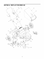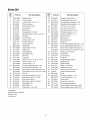
1
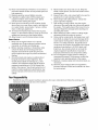
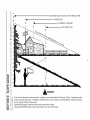
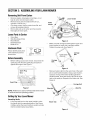
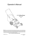
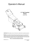
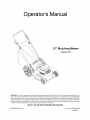
Operator's Manual
21" Mulching Mower
Series 540
Warning:
This unit is equipped with an internal combustion
engine and should not be used on or near any unimproved forest-cov-
ered, brush-covered or grass-covered land unless the engine's exhaust system is equipped with a spark arrester meeting applicable
local or state laws (if any). If a spark arrester is used, it should be maintained in effective working order by the operator. In the State
of California the above is required by law (Section 4442 of the California Public Resources Code). Other states may have similar laws.
Federal laws apply on federal lands. A spark arrester for the muffler is available through your nearest engine authorized service dealer
or contact the service department, P.O. Box 361131 Cleveland, Ohio 44136-0019.
MTD LLC, P.O. BOX361131CLEVELAND,OHIO44136-0019
PRINTED IN U.S.A.
Form No.769-00447B
(10/2003)
TABLEOFCONTENTS
Content
Page
3
6
7
9
Important Safe Operation Practices
Slope Guage
Assembling Your Lawn Mower
Know Your Lawn Mower
Operating Your Lawn Mower
Making Adjustments
10
11
Content
Maintaining Your Lawn Mower
Servicing Your Mower
Troubleshooting
Illustrated Parts List
Page
12
12
13
14
Warranty
16
FINDINGMODELNUMBER
This Operator's Manual is an important part of your new lawn mower. It will help you assemble, prepare and
maintain the unit for best performance. Please read and understand what it says.
Before you start assembling your new equipment, please locate the model plate on the
equipment and copy the information from it in the space provided below. A sample model plate is
also given below. You can locate the model plate by standing at the operating position and
looking down at the rear of the deck. This information will be necessary to use the
manufacturer's web site and/or help from the Customer Support Department or an authorized
service dealer.
Copy the model number here:
I
MTD
LLC
CLEVELAND,OH
330-220-4683
www.mtdproducts.com
Copy the serial number here:
]
44136
888-888-7318
CUSTOMER
SUPPORT
Please do NOTreturn theunit to the retailer from where it waspurchased,withoutfirst contactingCustomerSupport.
If you have difficulty assembling this product or have any questions regarding the controls, operation or
maintenance of this unit, you can seek help from the experts. Choose from the options below:
Visit mtdproducts.com for many useful suggestions. Click on Customer Support button and
you will get the four options reproduced here. Click on the appropriate button and help is
immediately available.
answer you are
looking for could be just
a mouse
"
f
c//cA awayf
answer
looking
a mouse
are
for could be just
"
f
c/_cA away_
To reach a Customer Support Representative, please call 1 (800) 800-7310.
En ine
The engine manufacturer is responsible for all engine-related issues with regards to
performance, power-rating, specifications, warranty and service. Please refer to the engine
manufacturer's Owner's/Operator's Manual, packed separately with your unit, for more
information.
SECTION1: IMPORTANT
SAFEOPERATION
PRACTICES
WARNING"
This symbol points out important safety instructions which, if not followed, could endanger
the personal safety and/or property of yourself and others. Read and follow all instructions in this manual
before attempting to operate this machine. Failure to comply with these instructions may result in personal
injury. When you see this symbol--HEED
ITS WARNING.
WARNING"
Engine exhaust, some of its constituents, and certain vehicle components contain or emit
chemicals known to State of California to cause cancer and birth defects or other reproductive harm.
WARNING"
This machine was built to be operated according to the rules for safe operation in this
manual. As with any type of power equipment, carelessness or error on the part of the operator can result in
serious injury. This machine is capable of amputating hands and feet and throwing objects. Failure to
observe the following safety instructions could result in serious injury or death.
GeneralOperation
1.
2.
3.
4.
5.
6.
Read this operator's manual carefully in its entirety
before attempting to assemble this machine. Read,
understand, and follow all instructions on the
machine and in the manual(s) before operation. Be
completely familiar with the controls and the proper
use of this machine before operating it. Keep this
manual in a safe place for future and regular
reference and for ordering replacement parts.
This machine is a precision piece of power
equipment, not a plaything. Therefore, exercise
extreme caution at all times. Your unit has been
designed to perform one job: to mow grass. Do not
use it for any other purpose.
Never allow children under 14 years old to operate
this machine. Children 14 years old and over
should read and understand the operation
instructions and safety rules in this manual and
should be trained and supervised by a parent. Only
responsible individuals who are familiar with these
safe operation rules should use this machine.
Thoroughly inspect the area where equipment is to
be used. Remove all stones, sticks, wire, bones,
toys and other foreign objects which could be
tripped over or picked up and thrown by the blade.
Thrown objects can cause serious personal injury.
Plan your mowing pattern to avoid discharge of
material toward roads, sidewalks, bystanders and
the like. Also, avoid discharging material against a
wall or obstruction which may cause discharged
material to ricochet back toward the operator.
To help avoid blade contact or a thrown object
injury, stay in the operator zone behind the handles
and keep bystanders, helpers, children and pets at
least 75 feet from the machine while it is in
operation. Stop machine if anyone enters the area.
Always wear safety glasses to protect your eyes
during equipment operation and while performing
an adjustment or repair. Thrown objects which
ricochet can cause serious injury to the eyes.
7.
Wear sturdy, rough-soled work shoes and closefitting slacks and shirts. Shirts and pants that cover
the arms and legs and steel-toed shoes are
recommended. Never operate this machine in bare
feet, sandals, slippery or light weight (e.g. canvas)
shoes.
8.
Do not put hands or feet near rotating parts or
under the cutting deck. Contact with the blade can
amputate hands and feet.
9. A missing or damaged discharge cover can cause
blade contact or thrown object injuries.
10. Many injuries occur as a result of the mower being
pulled over the foot during a fall caused by slipping
or tripping. Do not hold on to the mower if you are
falling; release the handle immediately.
11. Never pull the mower back toward you while you
are walking. If you must back the mower away from
a wall or obstruction first look down and behind to
5.
6.
7.
8.
avoid tripping and then follow these steps:
a. Step back from the mower to fully extend
your arms.
b. Be sure you are well balanced with sure
footing.
c. Pull the mower back slowly, no more than
half way toward you.
d. Repeat these steps as needed.
Do not operate the mower while under the influence
of alcohol or drugs.
Do not engage the self-propelled mechanism on
units so equipped while starting engine.
The blade control handle is a safety device. Never
attempt to bypass its operation. Doing so makes
the safety device inoperative and may result in
personal injury through contact with the rotating
blade. The blade control handle must operate
easily in both directions and automatically return to
the disengaged position when released.
Never operate the mower in wet grass. Always be
sure of your footing. A slip and fall can cause
serious personal injury. If you feel you are losing
your footing, release the blade control handle
immediately
andthebladewillstoprotatingwithin
3. Do not mow on wet grass. Unstable footing could
threeseconds.
cause slipping.
9. Mowindaylightorgoodartificiallight;walk,notrun.
10.Stopthebladewhencrossinggraveldrives,
Children
walkwaysorroads.
accidents can occur if the operator is not alert to
11.Iftheequipment
shouldstarttovibrateabnormally, Tragic
the presence of children. Children are often attracted to
stoptheengineandcheckimmediately
forthe
the mower and the mowing activity. They do not
cause.Vibrationisgenerallyawarningoftrouble.
understand the dangers. Never assume that children
12.Shuttheengineoffandwaituntilthebladecomes
will remain where you last saw them.
toacompletestopbeforeremoving
thegrass
1. Keep children out of the mowing area and under
catcherorunclogging
thechute.Thecuttingblade
the watchful care of a responsible adult other than
continues
torotatefora fewsecondsafterthe
the operator.
engineis shutoff.Neverplaceanypartofthebody
2. Be alert and turn mower off if a child enters the
inthebladeareauntilyouaresurethebladehas
area.
stoppedrotating.
3.
Before and while moving backwards, look behind
13.Neveroperatemowerwithoutpropertrail shield,
and down for small children.
discharge
cover,grasscatcher,bladecontrol
4. Use extreme care when approaching blind corners,
handleorothersafetyprotective
devicesinplace
doorways, shrubs, trees, or other objects that may
andworking.Neveroperatemowerwithdamaged
obscure your vision of a child who may run into the
safetydevices.Failuretodosocanresultin
mower.
personalinjury.
5.
Keep children away from hot or running engines.
14.Mufflerandenginebecomehotandcancausea
They
can suffer burns from a hot muffler.
burn.Donottouch.
6.
Never
allow children under 14 years old to operate
15.Onlyusepartsandaccessories
madebythe
a
power
mower. Children 14 years old and over
originalequipment
manufacturer
(O.E.M).Failure
should
read
and understand the operation
todosocanresultinpersonalinjury.
instructions
and
safety rules in this manual and
16.If situations
occurwhicharenotcoveredinthis
should
be
trained
and supervised by a parent.
manual,usecareandgoodjudgment.Contactyour
dealerforassistance.
Call1-800-800-7310
forthe
Service
nameofyournearestdealer.
SlopeOperation
Slopes are a major factor related to slip and fall
accidents which can result in severe injury. Operation
on slopes requires extra caution. If you feel uneasy on a
slope, do not mow it. Before operating this unit on a
slope or hilly area, use the slope gauge on page 6 to
measure slopes. If the slope is greater than 15
degrees, do not mow it.
Safe Handlingof Gasoline:
1. To avoid personal injury or property damage use
extreme care in handling gasoline. Gasoline is
extremely flammable and the vapors are explosive.
Serious personal injury can occur when gasoline is
spilled on yourself or your clothes which can ignite.
2. Wash your skin and change clothes immediately.
3. Use only an approved gasoline container.
4. Never fill containers inside a vehicle or on a truck or
Do:
1.
,
,
Mow across the face of slopes; never up and down.
Exercise caution when changing direction.
Watch for holes, ruts, rocks, hidden objects, or
bumps which can cause you to slip or trip. Tall
grass can hide obstacles.
Always be sure of your footing. A slip and fall can
cause serious personal injury. If you feel you are
losing your balance, release the blade control
handle immediately, and the blade will stop rotating
within 3 seconds.
Do Not:
1.
2.
Do not mow near drop-offs, ditches or
embankments, you could lose your footing or
balance.
Do not mow slopes greater than 15 degrees as
shown on the slope gauge.
5.
6.
7.
8.
9.
trailer bed with a plastic liner. Always place
containers on the ground away from your vehicle
before filling.
If possible, remove gas-powered equipment from
the truck or trailer and refuel it on the ground. If this
is not possible, then refuel such equipment on a
trailer with a portable container, rather than from a
gasoline dispenser nozzle.
Keep the nozzle in contact with the rim of the fuel
tank or container opening at all times until fueling is
complete. Do not use a nozzle lock-open device.
Extinguish all cigarettes, cigars, pipes and other
sources of ignition.
Never fuel machine indoors because flammable
vapors will accumulate in the area.
Never remove gas cap or add fuel while the engine
is hot or running. Allow engine to cool at least two
minutes before refueling.
10.Neveroverfillfueltank.Filltanktonomorethan½
inchbelowbottomoffillernecktoprovidespacefor
fuelexpansion.
11.Replacegasolinecapandtightensecurely.
12.If gasolineisspilled,wipeitofftheengineand
equipment.
Moveunittoanotherarea.Wait5
minutesbeforestartingtheengine.
13.Neverstorethemachineorfuelcontainer
inside
wherethereisanopenflame,sparkor pilotlightas
ona waterheater,spaceheater,furnace,clothes
dryerorothergasappliances.
14.Toreducefirehazard,keepmowerfreeofgrass,
leaves,orotherdebrisbuild-up.
Cleanupoilorfuel
spillageandremoveanyfuelsoakeddebris.
15.Allowmowertocool5 minutesbeforestoring.
GeneralService:
1.
2.
3.
Never run an engine indoors or in a poorly
ventilated area. Engine exhaust contains carbon
monoxide, an odorless and deadly gas.
Before cleaning, repairing, or inspecting, make
certain the blade and all moving parts have
stopped. Disconnect the spark plug wire and
ground against the engine to prevent unintended
starting.
Check the blade and engine mounting bolts at
frequent intervals for proper tightness. Also,
visually inspect blade for damage (e.g., bent,
cracked, worn) Replace blade with the original
equipment manufacture's (O.E.M.) blade only,
listed in this manual. "Use of parts which do not
meet the original equipment specifications may
lead to improper performance and compromise
safety!"
4.
Mower blades are sharp and can cut. Wrap the
blade or wear gloves, and use extra caution when
servicing them.
5. Keep all nuts, bolts, and screws tight to be sure the
equipment is in safe working condition.
6. Never tamper with safety devices. Check their
proper operation regularly.
7. After striking a foreign object, stop the engine,
disconnect the spark plug wire and ground against
the engine. Thoroughly inspect the mower for any
damage. Repair the damage before starting and
operating the mower.
8. Never attempt to make a wheel or cutting height
adjustment while the engine is running.
9. Grass catcher components, discharge cover, and
trail shield are subject to wear and damage which
could expose moving parts or allow objects to be
thrown. For safety protection, frequently check
components and replace immediately with original
equipment manufacturer's (O.E.M.) parts only,
listed here. Use of parts which do not meet the
original equipment specifications may lead to
improper performance and compromise safety.
10. Do not change the engine governor setting or
overspeed the engine. The governor controls the
maximum safe operating speed of the engine.
11. Maintain or replace safety and instruction labels, as
necessary.
12. Observe proper disposal laws and regulations.
Improper disposal of fluids and materials can harm
the environment.
YourResponsibility
•
Restrict the use of this power machine to persons who read, understand and follow the warnings and
instructions in this manual and on the machine.
DAN@mR
/ WARNINGo
o
E
SIGHT AND HOLD THIS LEVEL WITH A VERTICAL TREE
i,,II
t-
A POWER POLE
I
O
A CORNER OF A BUILDING
I
OR A FENCE POST
QI
O
cO
r_
d)
o
*6
r-
E
cO
o
(D
I
rd)
o
15 °
t,D
o(D
,iI
"_
WARNING
O3
64
o
Do not mow on inclines with a slope in excess of 15 degrees (a rise of approximately 2-1/2 feet every 10 feet). A riding mower could
overturn and cause serious injury. If operating a walk-behind mower on such a slope, it is extremely difficult to maintain your footing
and you could slip, resulting in serious injury.
Operate RIDING mowers up and down slopes, never across the face of slopes.
Operate WALK-BEHIND mowers across the face of slopes, never up and down slopes.
SECTION3: ASSEMBLING
YOURLAWNMOWER
RemovingUnitFromCarton
•
•
•
•
Remove staples, break glue on top flaps, or cut
tape at carton end and open carton.
Remove loose parts if included with unit (i.e.,
operator's manual, etc.)
Cut along corners, lay the carton down flat, and
remove all packing material.
Roll or slide unit out of carton and check carton
Lower Handle
Handle
Upper
Handle
},_acket
thoroughly for loose parts.
LoosePartsin Carton
•
•
•
•
•
°N
Grass Bag
Side Discharge Chute
Rear Wheels
Hardware Pack
Bottle of Oil
Figure 2
Make sure that carriage bolt through the upper and
lower handles on each side is properly seated.
Tighten the wing nuts. See Figure 3.
HardwarePack
Please identify each piece
of the hardware pack as
shown here.
Carriage
Bolt
Wing Nut
Carriage
Bolt
Tighten these
wing nuts
BeforeAssembly
•
Carriage
Bolt
Before setting up your lawn mower, disconnect the
spark plug wire from the spark plug and ground
against the engine. See Figure 1.
Figure 3
park Plug
IIWire\
\
"
Remove hairpin clip from the outer hole of the weld
pin on each handle brackets. Using a pair of pliers,
squeeze one leg of the lower handle against the
handle bracket. Insert the hairpin clip into the inner
hole on the weld pin. Repeat on the other side. See
Figure 4.
Carriage Bolt
Figure 1
NOTE: Reference to right or left hand side of the mower
is observed from the operating position.
Pin
Wing
\\\\\
/
/
SettingUpYourLawnMower
AssemblingHandle
•
Lift up and pull back on the upper handle to raise
the handle into the operating position. See Figure
2. Make certain the lower handle is seated securely
into the handle bracket assemblies.
Hairpin Clip
Figure 4
•
•
After moving the hairpin clip, insert the carriage
bolt, from the hardware pack, in the upper hole on
the handle mounting bracket and secure with
plastic wing nut from the hardware pack. See
Figure 4. Repeat on the other side.
Fasten the cable to the lower handle with the two
cable ties found on the lower handle. Pull the cable
ties tight and trim off the excess. See Figure 5.
•
•
AssemblingGrassCatcher
NOTE: If the grass catcher came pre-assembled,
proceed to the next section. If it came unassembled,
follow the steps below to assemble it first, before
attaching to the mower.
Cable Tie
Lower
Handle
Insert frame into grass bag with the black plastic
side on the bottom of bag. See Figure 8.
Slip the openings in the side of the plastic channel
on bag over the hooks on the grass catcher frame.
Secure bag to the frame by working the six plastic
channels on bag over frame. All of the plastic channels except the center top of the bag attach from
the outside of bag. The center top of the bag
attaches from inside the bag. See Figure 8.
Grass Catcher
Frame
Insert frame
into bag
Figure 5
NOTE: Your mower is shipped with the handle in the
higher position. If you wish to lower the height of the
handle, refer to the Adjustment Section at this time.
Attaching
RearWheels
•
With the spark plug wire disconnected and
grounded, hold the blade control handle against the
upper handle, and pull the rope out of the engine.
Slip the rope through the rope guide as shown
below. Tighten the wing nut holding the rope guide
to the upper handle.
Remove the hex flanged nut on the rear axle from
each side and place the rear wheel on the axle. See
Figure 6. Reinsert the flanged nut into the axle as
shown, and tighten securely. Repeat on other side.
Rear Wheel
\
\
Rear Axle
\
Grass Bag
Hex
Nut
Plastic
Channel
\
Grass Catcher
Assembly
Complete
/
Figure 6
Attaching
StarterRope
The rope guide is already attached to the right side of
the upper handle of your mower. See Figure 7.
Wing Nut
_
Figure 8
Upper Handle
J
AttachingGrassCatcher& Chute
Starter Ro
/
Rope Guide
Lower
Figure 7
Handle
_
ARNING:
Never
operate
mower
unless
the hooks
on the
grass the
catcher
are
firmly seated on the chute pivot rod, and the
rear discharge door rests firmly against the top
of the grass catcher.
IMPORTANT:
Makesurecableisroutedtotheoutsideof
thehandlesothatitisnotinthewaywhenattaching
the
grasscatcher.
Liftthereardischarge
dooronthemower.
Placethehooks,foundonbothsidesofthegrass
catcherframe,overthechutedoorpivotrodatthe
rearofthemower.Release
thereardischarge
door.
SeeFigure9.
Rear Discharge Door
AttachingSide-Discharge Chute
•
Remove the grass catcher and let the discharge
door close.
•
On the right side of the mower, lift the mulching
plug and slide the two hooks of the side-discharge
chute under the hinge pin on the mulching plug
assembly. Lower the mulching plug. See Figure 10.
IMPORTANT:Do not remove the mulching plug at any
time, even when you are not mulching.
Plug
Mulching
nge
"_
Grass
_ Deflector
Side
', f
I_
Figure 10
Figure 9
To remove the grass catcher, lift the rear discharge
door on the mower, lift the grass catcher up and off
the pivot rod. Release the rear discharge door.
UsingMulch Plug
•
Lift the mulch plug and remove the discharge chute
up and away from the mower. Let mulch plug rest
against the deck. Operate mower without the grass
catcher. Refer to page
SECTION4: KNOWYOURLAWNMOWER
Upper Handle _
Control
Handle
Recoil
Starter
Rear Cutting Height
Adjustment Lever
Catcher
Side-Discharge
Chute
Mulchin
Plug
Figure 11
Front Cutting Height
Adjustment
Lever
Read this operator's manual and safety rules before
operating your lawn mower. Compare the illustration in
Figure 11 with your lawn mower to familiarize yourself
with the location of various controls and adjustments.
Save this manual for future reference.
,_
Cutting HeightAdjustmentLevers
These levers are located on each wheel and are used
to adjust the cutting height. These levers have to be at
the same relative position to ensure uniform cut.
RecoilStarter
The recoil starter is attached to the right upper handle.
Stand behind the unit and pull the recoil starter rope to
start the unit.
WARNING"
Theinoperation
of any being
lawn
mower can result
foreign objects
thrown into the eyes, which can damage your
eyes severely. Always wear safety glasses
while operating the mower, or while performing
any adjustments or repairs on it.
GrassCatcher
The grass catcher, located at the rear of the mower, is
used to bag the grass clippings for disposal at another
site. Once the bag is full, it has to be removed from the
mower and emptied before any further mowing.
BladeControlHandle
The blade control handle is located on the upper handle
of the mower. The blade control handle must be
MulchingPlug
depressed in order to operate the unit. Release blade
control handle to stop engine and blade.
,_
Instead of collecting grass clippings in a grass catcher,
this mower has the option of recirculating the clippings
back to the lawn. This is called mulching. Remove the
grass catcher and the side-discharge chute from the
mower, and operate with the mulching plug only for this
purpose.
WARNING"
blade
controlto mechanism
a safety device.This
Never
attempt
bypass its is
operations.
SECTION5: OPERATING
YOURLAWNMOWER
StartingEngine
,_
•
WARNING"
understand,
and follow
all
instructions andRead,
warnings
on the machine
and
in this manual before operating.
NOTE: You must service the engine with oil and
gasoline before starting the mower for the first time.
Check oil and gasofine levels and fill up as necessary
for subsequent starts.
•
•
Gas& Oil Fill-Up
•
•
Check oil level and add oil if necessary. Follow
relevant instructions in the engine manual for this.
Service the engine with gasoline as instructed in
the engine manual.
WARNING:
•
between each push. In cold weather around 55 ° F
or below, prime five times. Do not prime to restart a
warm engine after a short shutdown.
Standing behind the mower, depress the blade
control handle and hold it against the upper handle.
Grasp starter handle and pull rope out slowly until
engine reaches the start of compression cycle
(rope will pull slightly harder at this point). Let the
rope rewind slowly.
Pull rope with a rapid, continuous, full arm stroke.
Keeping a firm grip on the starter handle, let the
rope rewind slowly.
WARNING:
Use extreme care when
handling gasoline. Gasoline is extremely
flammable and the vapors are explosive. Never
fuel the machine indoors or while the engine is
hot or running. Extinguish cigarettes, cigars,
pipes and other sources of ignition.
Be sure no one other than the
operator is standing near the lawn mower while
starting engine or operating mower.
WARNING:
Never run engine indoors or in
enclosed, poorly ventilated areas. Engine
exhaust contains carbon monoxide, an
odorless and deadly gas.
BeforeStartingMower
•
Push primer three times. Wait about two seconds
WARNING:
Attach spark plug wire to spark plug. Make certain
the metal cap on the end of the spark plug wire
(inside the rubber boot) is fastened securely over
the metal tip on the spark plug.
Keep hands, feet, hair and
loose clothing away from any moving parts on
engine and lawn mower.
10
StoppingEngine
Mulching
•
Release blade control handle to stop the engine
and the blade.
•
Disconnect spark plug wire and move away from
spark plug to prevent accidental starting.
For effective mulching, do not cut wet grass. New or
thick grass may require a narrower cut. If the grass has
grown in excess of 4", mulching is not recommended.
Mow using the side discharge to reduce the grass
height to 3.25" maximum before mulching.
UsingYourLawn Mower
•
•
,_
•
•
BaggingGrassClippings
You can use your mower as a mulching mower or a
rear bagger.
Be sure that the lawn is clear of stones, sticks, wire,
or other objects which could damage lawn mower
or engine.
You can use the grass catcher bag to collect clippings
while you are operating the mower.
•
•
•
object, stop the Ifengine.
WARNING"
the mower
Remove
strikesspark
a foreign
plug
wire from the spark plug and thoroughly inspect
for any damage. Repair the damage promptly
before restarting and operating the mower.
•
Forbestresults, donotcutwetgrass.
New grass or
thick grass may require a narrower cut.
For a healthy lawn, always cut off one-third or less
of the total length of the grass.
Attach grass catcher following instructions on page
8 of this manual. Grass clippings will automatically
collect in the bag as you run the mower.
Operate the mower till the grass bag is full.
Stop engine completely by releasing the blade
control handle. Make sure that the unit has come to
a complete stop.
Lift discharge door and pull grass bag up and away
from the mower to dispose of the grass clippings.
SECTION6: MAKINGADJUSTMENTS
,_
adjustments
engineany
and
WARNING: without
Do notfirst
at stopping
any time make
disconnecting spark plug wire.
Notch
HandleHeightAdjustment
Lower
Handle
Your mower is shipped with the handle in the higher
height position. To lower the height proceed as follows:
•
•
•
•
•
•
Height
Adj.
Lever
Remove the starter rope from the rope guide.
Remove the upper handle by removing the hand
knobs and carriage bolts. Lay the upper handle out
of the way, being careful not to bend or kink the
cables.
A
Figure 12
Reassemble the upper handle to the lower handle.
Attach the starter rope as instructed in the
Assembly Section.
Remove the hairpin clips from the weld pins on the
handle brackets and remove the wing nuts and
carriage bolts from the upper hole on the handle
mounting bracket. Press out on the legs of the
lower handle and remove lower handle from the
mower.
Turn lower handle around so the notch on the
CuttingHeightAdjustment
For rough or uneven lawns, move the height
adjustment lever to a higher position. This will help stop
scalping of the grass.
bottom of the lower handle is facing forward.
See Figure 12A.
Reassemble the handle, placing the bottom holes
in the handle over the weld pins in the handle
mounting bracket.
Place the hairpin clips in the inner holes in the weld
pins and insert the carriage bolts the upper hole on
the handle mounting bracket and secure with
plastic wing nuts. Repeat on the other side.
An adjusting plate and thumb lever at each wheel
position provides cutting height adjustment. Each
adjusting plate has nine height positions. Height of cut
will change when you move the thumb lever from one
position to another.
•
11
Simply depress the lever towards the wheel and
move the lever assembly to desired position. See
Figure 12B. All wheels must be placed in the same
relative position.
SECTION7: MAINTAININGYOURLAWNMOWER
•
,i_
WARNING" the Always
stopwire
the before
engine and
disconnect
spark plug
performing any maintenance work or
adjustments on your lawn mower.
Lubrication
BladeControl Handle
CleaningMower
•
The underside of the mower deck should be cleaned
after each use to prevent any build-up of grass
clippings, leaves, dirt, or other debris.
•
,_
•
Lubricate the pivot points on the blade control
handle at least once a season with light oil. The
blade control must operate freely in both directions.
Wheels
NOTE: We do not recommend the use of pressure
washers or garden hose to clean your unit. These may
cause damage to electric components,
spindles,
pulleys, bearings, or the engine. The use of water will
result in shortened life and reduce serviceability.
•
Put the mower back on its wheels on the ground. If
you had put plastic under the gas cap, make sure to
remove it now.
•
Disconnect spark plug wire. Drain the gasoline from
the lawn mower, or place a piece of plastic under
the gas cap.
Tip the mower so that it rests on the housing. Keep
the side with the air cleaner facing up. Hold the
mower firmly.
Lubricate the wheels and bearings, if so equipped,
at least once a season with light oil or engine oil.
Also, if the wheels are removed for any reason,
lubricate the surface of the axle bolt and the inner
surface of the wheel with light oil.
Rear DischargeDoor
•
Lubricate the torsion spring and the pivot point on
each end of the rear discharge door using a light oil.
This will prevent rusting of the discharge door.
EngineCare
Follow the accompanying engine manual for detailed
list and instructions.
90 degrees in any
WARNING"
Never
directions
tip the mower
and do more
not leave
than
the mower tipped for any length of time. Oil can
drain into the upper part of the engine causing
a starting problem.
,_
Scrape and clean the underside of the deck with a
suitable tool. Do not spray with water.
WARNING:
surrounding areas
Make
while
surethe
to mower
avoid muffler
engineand
is
hot because temperature of these areas of the
engine may exceed 150 ° F.
SECTION8: SERVICING
THEMOWER
BladeCare
•
,_
•
blade for sharpening
WARNING"
When or
removing
replacement,
the cutting
protect
your hands with a pair of heavy gloves or use a
heavy rag to hold the blade.
Remove the bolt and the blade bell support which
hold the blade and the blade adapter to the engine
crankshaft. See Figure 13.
Remove the blade and the adapter from the
crankshaft.
Blade
Adapter
Periodically inspect the blade adapter for cracks,
especially if you strike a foreign object. Replace when
necessary.
S
Removingthe Blade
•
Disconnect spark plug wire from spark plug.
•
Turn mower on its side making sure that the air filter
and the carburetor are up.
Blade Bell
Support
Bolt
Figure 13
12
Sharpening the Blade
•
•
The blade can be sharpened with a file or on a
grinding wheel. Do not attempt to sharpen the
blade while it is still on the mower.
•
•
Follow the original angle of grind as a guide. Make
sure that each cutting edge receives an equal
amount of grinding to prevent an unbalanced blade.
•
,_
NOTE: To ensure safe operation of your mower,
periodically check the blade bolt for correct torque.
excessive vibration
WARNING"
An unbalanced
when rotating
blade
at high
will cause
speeds. It may cause damage to the mower,
and could break causing personal injury.
Replacing
RearFlap
Balancingthe Blade
•
The blade can be tested by balancing it on a round
shaft screwdriver. Remove metal from the heavy
side until it balances evenly. It is recommended that
the blade always be removed from the adapter
when testing for balance.
•
•
To remove rear flap, cut off the flat end of the wire
rod which secures it to the deck.
Attach the new flap and new rod to deck, bending
the ends of the new rod over to secure to deck.
StoringYourLawnMower
Installingthe Blade
•
Before reinstalling the blade and the blade adapter
to the unit, lubricate the engine crankshaft and the
inner surface of the blade adapter with light oil.
•
Be sure to install the blade with the side of the
•
Place the blade on the adapter. Be certain the
blade is aligned and seated on the blade adapter
flanges.
Place blade bell support on blade. Make sure the
notches on the blade bell support are aligned with
small holes in the blade.
Replace hex bolt and tighten hex bolt to torque: 450
in. Ibs. min., 600 in. Ibs. max.
The following steps should be taken to prepare your
lawn mower for storage.
blade marked "Bottom" (or with part number) facing
the ground when the mower is in the operating
position.
Slide the blade adapter onto the engine crankshaft.
•
Clean and lubricate mower thoroughly as described
in the lubrication instructions.
•
Refer to engine manual for correct engine storage
instructions.
•
Coat mower's cutting blade with chassis grease to
prevent rusting.
Store mower in a dry, clean area. Do not store next
to corrosive materials, such as fertilizer.
•
SECTION9: TROUBLESHOOTING
Problem
Engine fails to start
Engine runs erratic
Engine overheats
Excessive vibration
Mower will not mulch grass
Uneven cut
Cause
Remedy
1.
2.
3.
4.
5.
6.
1.
2.
3.
4.
5.
6.
1.
2.
3.
1.
2.
1.
Blade control handle disengaged.
Spark plug wire disconnected.
Fuel tank empty or stale fuel.
Blocked fuel line.
Faulty spark plug.
Engine flooded
Spark plug wire loose.
Blocked fuel line or stale fuel.
Vent in gas plugged.
Water or dirt in fuel system.
Dirty air cleaner.
Carburetor out of adjustment.
Engine oil level tow.
Air flow restricted.
Carburetor not adjusted properly.
Cutting blade loose or unbalanced.
Bent cutting blade.
Wet grass.
1.
2.
3.
4.
5.
6.
1.
2.
3.
4.
5.
6.
1.
2.
3.
1.
2.
1.
2.
Excessively high grass.
2.
3.
1.
2.
Dull blade.
3,
Wheels not positioned correctly.
Dull blade.
1.
2.
13
Engage blade control handle.
Connect wire to spark plug.
Fill tank with clean, fresh gasoline.
Clean fuel line.
Clean, adjust gap, or replace.
Wait a few minutes to restart, do not prime.
Connect and tighten spark plug wire.
Clean fuel line; fill tank with fresh gasoline
Clear vent.
Drain fuel tank. Refill with fresh fuel.
Clean air cleaner.
Adjust carburetor.
Fill crankcase with proper oil.
Remove blower housing and clean.
Adjust carburetor.
Tighten blade and adapter. Balance blade.
Replace blade.
Do not mow when grass is wet; wait until
later to cut.
Mow once at a high cutting height, then mow
again at desired height.
Sharpen or replace blade.
Place all four wheels in same position.
Sharpen or replace blade.
SECTION10: PARTSLISTFORSERIES540
2
\
13
/
4
5
2
11
/
9
31
16
34
\\
\
19
24
23
49
37
51
50
56
14
/
/
Series540
Ref,
No,
Part No.
1.
749-1092A
2.
Ref.
No,
Part Description
Part No.
Part Description
33.
712-3005
747-1161A
Upper Handle
Control Handle
34.
710-0703
Hex Carriage Screw 1/4-20
3.
710-1270
C-Sunk Screw 1/4-20 x 1.3"
35.
687-02033
Handle Bracket Assembly -- RH
4.
5.
746-0883
712-0324
Throttle Housing
Hex Lock Nut 1/4-20
36.
687-02031
710-1652
Handle Bracket Assembly -- LH
TT Screw 1/4-14 x .625
6.
720-0279
Handle Knob
37.
710-0216
Hex Screw 3/8-16 x 0.75
7.
710-1205
Rope Guide
38.
710-0514
Hex Cap Screw 3/8-16 x 1.0
8.
710-1174
39.
687-02039
Pivot Bar Assembly -- RH
9.
736-0451
Carriage Bolt 5/16-18 x 2"
Shoulder Washer .320 ID x .930 OD
687-02040
10.
11.
720-0284
749-0928A
Wing Nut
Lower Handle
40.
42.
738-0507B
732-0866
Pivot Bar Assembly -- LH
Shoulder Screw
12.
746-0957
Control Cable 37.25"
43.
720-0312
Grip: Spring Lever
746-1130
Control Cable 40"
45.
712-0397
Wing Nut
746-1137
Control Cable 53"
46.
687-02074
Front Height Adjuster Assembly -- RH
13.
664-04005
687-02075
Front Height Adjuster Assembly -- LH
14.
15.
747-04080
714-0104
Grass Bag
Grass Catcher Frame
47.
734-1987
734-2005A
Front Wheel: 8-Spoke Bar Gray 8 x 2
16.
731-04134
Grass Bag Door
49.
712-0431
17.
782-5007A
50.
782-5002A
Flange Lock Nut 3/8-16
Front Baffle
18.
732-0700
Rear Mulch Plug
Wire Rod
51.
732-1014
Torsion Spring
19.
731-1236
Traitshield
52.
747-0710
Hinge Pin
20.
21.
750-04162
732-04090
Spacer .375 O.D. x .50 I.D. x 1.02"
53.
782-7006
Hinge Mounting Bracket
Torsion Spring -- RH
54.
731-04161
Mulching Plug
732-04089
Hairpin Clip
Flange Lock Nut 3/8-16
Spring Lever
Front Wheel: Zag Trd. Gray 8 x 2.125 1
Torsion Spring -- LH
55.
748-0376C
Blade Adapter
687-02056
Handle Bracket Assembly -- RH
56.
742-0741
Blade: 21" Mulching
687-02057
Handle Bracket Assembly -- LH
57.
736-0524A
Blade Bell Support
23.
734-04082
Rear Wheel: 8-Spoke Bar Gray 12 x 2
58.
710-1044
Hex Cap Screw 3/8-24 x 1.5
Rear Wheel: Zag Trd. Gray 12 x 2.125
Deck 21"
59.
15261A
24.
734-04093
787-01104
60.
720-0426
Height Adjustment Plate
Knob
25.
710-0654A
Hex Washer Screw 3/8-16 x 1.0
61.
687-02077
Pivot Bar Assembly -- RH
26.
736-0270
Bell Washer .265 ID x .75 OD
28.
712-0130
Hex Lock Nut 3/8-16
29.
736-0356
30.
31.
32.
22.
687-02076
Pivot Bar Assembly -- LH
62.
732-0404
Bell Washer .390 ID x .380 OD
64.
747-0996
Spring Lever
Chute Door Pivot Rod
782-5004
782-5003
Rear Baffle - RH
Rear Baffle - LH
65.
731-04177
Side Discharge Deflector
66.
731-1426A
Hubcap Radial Spoke Yeltow1" (NS)
710-1017
Tap Screw 1/4-14 x .625.
731-0981A
Hubcap Radial Spoke Gray 1"(NS)
1"If equipped
(NS) Not shown on page 16
RH Right Hand
LH Left Hand
15
MANUFACTURER'S
LIMITED WARRANTY
The limited warranty set forth below is given by MTD LLC with
respect to new merchandise purchased and used in the
United States, its possessions and territories.
"MTD"warrants this product against defects in material and
workmanship for a period of two (2) years commencing on the
date of original purchase and wilt, at its option, repair or
replace, free of charge, any part found to be defective in
materials or workmanship. This limited warranty shall only
apply if this product has been operated and maintained in
accordance with the Operator's Manual furnished with the
product, and has not been subject to misuse, abuse,
commercial use, neglect, accident, improper maintenance,
alteration, vandalism, theft, fire, water, or damage because of
other peril or natural disaster. Damage resulting from the
installation or use of any part, accessory or attachment not
approved by MTD for use with the product(s) covered by this
manual will void your warranty as to any resulting damage.
Normal wear parts are warranted to be free from defects in
material and workmanship for a period of thirty (30) days from
the date of purchase. Normal wear parts include, but not
limited to items such as: batteries, belts, blades, blade
adapters, grass bags, rider deck wheels, seats, snow thrower
skid shoes, shave plates, auger spiral rubber and tires.
HOW TO OBTAIN SERVICE: Warranty service is available,
WITH PROOF OF PURCHASE, through your local authorized
service dealer. To locate the dealer in your area, check your
Yellow Pages, or contact MTD LLC at P.O. Box 361131,
Cleveland, Ohio 44136-0019, or call 1-800-800-7310 or 1330-220-4683 or tog on to our Web site at
www.mtdproducts.com.
This limited warranty does not provide coverage in the
following cases:
a,
b,
C.
d,
The engine or component parts thereof. These items
may carry a separate manufacturer's warranty. Refer
to applicable manufacturer's warranty for terms and
conditions.
Log splitter pumps, valves, and cylinders have a
separate one year warranty.
Routine maintenance items such as lubricants, filters,
blade sharpening, tune-ups, brake adjustments, clutch
adjustments, deck adjustments, and normal
deterioration of the exterior finish due to use or
e,
f,
g.
FOR:
MTD does not extend any warranty for products sold or
exported outside of the United States, its possessions
and territories, except those sold through MTD's
authorized channels of export distribution.
Replacement parts that are not genuine MTD parts.
Transportation charges and service calls.
No implied warranty, including any implied warranty of
merchantability of fitness for a particular purpose,
applies after the applicable period of express written
warranty above as to the parts as identified. No other
express warranty, whether written or oral, except as
mentioned above, given by any person or entity,
including a dealer or retailer, with respect to any product,
shall bind MTD. During the period of the warranty, the
exclusive remedy is repair or replacement of the product
as set forth above.
The provisions as set forth in this warranty provide the
sole and exclusive remedy arising from the sale. MTD
shall not be liable for incidental or consequential loss or
damage including, without limitation, expenses incurred
for substitute or replacement lawn care services or for
rental expenses to temporarily replace a warranted
product.
Some states do not allow the exclusion or limitation of
incidental or consequential damages, or limitations on how
long an implied warranty lasts, so the above exclusions or
limitations may not apply to you.
In no event shall recovery of any kind be greater than the
amount of the purchase price of the product sold. Alteration
of safety features of the product shall void this warranty.
You assume the risk and liability for toss, damage, or injury to
you and your property and/or to others and their property
arising out of the misuse or inability to use the product.
This limited warranty shall not extend to anyone other than the
original purchaser or to the person for whom it was purchased
as a gift.
HOW STATE LAW RELATES TO THIS WARRANTY: This
limited warranty gives you specific legal rights, and you may
also have other rights which vary from state to state.
IMPORTANT: Owner must present Original Proof of
Purchase to obtain warranty coverage.
exposure.
Service completed by someone other than an
authorized service dealer.
MTD LLC, P.O.BOX361131CLEVELAND,OHIO44136-0019; Phone:1-800-800-7310,1-330-220-4683