1
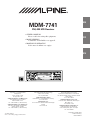
R
EN
MDM-7741
FM/AM MD Receiver
• OWNER'S MANUAL
Please read before using this equipment.
FR
• MODE D'EMPLOI
Veuillez lire avant d’utiliser cet appareil.
• MANUAL DE OPERACIÓN
Léalo antes de utilizar este equipo.
ES
ES
D.A.P
RPT ALL M.I.X.
F
DX
SEEK
ST LD
IT
ALPINE ELECTRONICS, INC.
Tokyo office: 1-1-8 Nishi Gotanda,
Shinagawa-ku,
Tokyo 141-8501, Japan
Tel.: (03) 3494-1101
ALPINE ELECTRONICS OF AMERICA, INC.
19145 Gramercy Place, Torrance,
California 90501, U.S.A.
Tel.: 1-800-ALPINE-1 (1-800-257-4631)
ALPINE ELECTRONICS OF CANADA, INC.
Suite 203, 7300 Warden Ave. Markham,
Ontario L3R 9Z6, Canada
Tel.: 1-800-ALPINE-1 (1-800-257-4631)
Je ll Moon Hwa Co.
23-5, 1 Ga, Pil-dong, Jung-gu, Seoul, Korea
ALPINE ELECTRONICS OF AUSTRALIA PTY. LTD.
6-8 Fiveways Boulevarde Keysborough,
Victoria 3173, Australia
Tel.: (03) 9769-0000
ALPINE ELECTRONICS GmbH
Kreuzerkamp 7-11 40878 Ratingen, Germany
Tel.: 02102-45 50
ALPINE ITALIA S.p.A.
Via C. Colombo 8, 20090 Trezzano Sul Naviglio
MI, Italy
Tel.: 02-48 47 81
ALPINE ELECTRONICS FRANCE S.A.R.L.
(RCS PONTOISE B 338 101 280)
98, Rue De La Belle Etoile, Z.I. Paris Nord Il
B.P. 50016 F-95945, Roissy, Charles De Gaulle
Cedex, France
Tel.: 01-48 63 89 89
ALPINE ELECTRONICS OF U.K., LTD.
13 Tanners Drive, Blakelands, Milton Keynes
MK14 5BU, U.K.
Tel.: 01908-61 15 56
ALPINE ELECTRONICS DE ESPAÑA, S.A.
Portal De Gamarra 36, Pabellón 32
01013 Vitoria (Alava)-Apdo. 133, Spain
Tel.: 34-45-283588
Designed by ALPINE Japan
Printed in Korea (Y)
68P01149K80-O
SE
CD changer for MDM-7741
Changeur CD pour MDM-7741
Cambiador de CD para MDM-7741
CHA-S624
CHA-1214
CHM-S620
Alpine CD Changers Give You More!
More musical selections, more versatility, more convenience.
An Alpine CD Changer adds more musical choices to your sound system. All models can be controlled from
Alpine head units and deliver excellent sound quality. The CHA-S624 is a high-performance 6-disc changer
with a new M DAC, Ai-NET compatibility, Optical Digital Output, 150 Disc Title Memory and CD TEXT.
The CHA-1214 Ai-NET model holds 12 discs, and the CHM-S620 M-Bus model is a super-compact 6-disc
changer.
Changeurs de CD Alpine : vous avez le choix!
Plus de sélections musicales, plus de souplesse, plus de confort.
Un changeur de CD Alpine permet d'augmenter la plage des sélections musicales de votre système embarqué.
Tous les modèles peuvent être contrôlés à partir des autoradios Alpine et offrent une excellente qualité audio.
Le modèle CHA-S624 est un changeur 6 disques ultra performant compatible Ai-NET et équipé d'un
convertisseur N/A standard, d'une sortie optique numérique, d'une mémoire d'une capacité de 150 titres et de
la fonction CD TEXT. Le modèle CHA-1214 Ai-NET peut contenir 12 disques. Le modèle CHM-S620 MBus est un changeur 6 disques super compact.
¡Los cambiadores Alpine de CD le ofrecen más!
Más selecciones musicales, más versatilidad y más ventajas.
Un cambiador Alpine de CD añade más opciones musicales a su equipo de sonido. Todos los modelos
pueden controlarse desde las unidades principales de Alpine y proporcionar un sonido de calidad
excepcional. El modelo CHA-S624 es un cambiador de 6 discos de alto rendimiento con el nuevo DAC "M"
y compatibilidad con Ai-NET, salida digital óptica, memoria de títulos de 150 discos y TEXTO CD. El
modelo CHA-1214 Ai-NET admite 12 discos y el modelo CHM-S620 Bus-M es un cambiador de 6 discos y
tamaño reducido.
ENGLISH
Contents
Operating Instructions
WARNING
MD Player Operation
Normal Play and Pause ................................... 10
Music Sensor (Skip) ........................................ 10
Fast Forward and Backward ........................... 10
WARNING .................................................. 2
Repeat Play ..................................................... 11
CAUTION ................................................... 2
M.I.X. (Random Play) .................................... 11
PRECAUTIONS ......................................... 2
Scanning Programs ......................................... 11
Basic Operation
To Display MD Title ....................................... 11
Controlling CD Changer (Optional) ............... 11
Detaching the Front Panel ................................. 4
Attaching the Front Panel ................................. 4
Initial System Start-Up ..................................... 4
Information
In Case of Difficulty ....................................... 12
Specifications .................................................. 13
Turning Power On and Off ............................... 4
Subwoofer On and Off ...................................... 5
Adjusting Volume/Bass/Treble/
Installation and Connections
Balance (Between Left and Right)/
Warning ........................................................... 14
Fader (Between Front and Rear) ................... 5
Caution ............................................................ 14
Turning Loudness On/Off ................................. 5
Precautions ...................................................... 14
Audio Mute Function ........................................ 5
Installation ...................................................... 15
Setting Bass Frequency ..................................... 5
Connections .................................................... 16
Adjusting the Contrast ...................................... 5
Displaying Time ................................................ 6
LIMITED WARRANTY
Setting Time ...................................................... 6
Radio Operation
Manual Tuning .................................................. 7
Automatic Seek Tuning .................................... 7
Manual Storing of Station Presets .................... 8
Automatic Memory of Station Presets .............. 8
Storing into Direct Access Preset (D.A.P.)
Band ............................................................... 9
Tuning to Preset Stations .................................. 9
• US and foreign patents licensed from Dolby Laboratories
Licensing Corporation.
1-EN
WARNING
WARNING
This symbol means important instructions.
Failure to heed them can result in serious
injury or death.
DO NOT OPERATE ANY FUNCTION THAT TAKES
YOUR ATTENTION AWAY FROM SAFELY DRIVING
YOUR VEHICLE.
Any function that requires your prolonged attention
should only be performed after coming to a complete stop.
Always stop the vehicle in a safe location before
performing these functions. Failure to do so may result in
an accident.
KEEP THE VOLUME AT A LEVEL WHERE YOU CAN
STILL HEAR OUTSIDE NOISE WHILE DRIVING.
Failure to do so may result in an accident.
MINIMIZE DISPLAY VIEWING WHILE DRIVING.
Viewing the display may distract the driver from looking
ahead of the vehicle and cause an accident.
DO NOT DISASSEMBLE OR ALTER.
Doing so may result in an accident, fire or electric shock.
USE THIS PRODUCT FOR MOBILE 12V
APPLICATIONS.
Use for other than its designed application may result in
fire, electric shock or other injury.
USE THE CORRECT AMPERE RATING WHEN
REPLACING FUSES.
CAUTION
This symbol means important instructions.
Failure to heed them can result in injury or
material property damage.
HALT USE IMMEDIATELY IF A PROBLEM APPEARS.
Failure to do so may cause personal injury or damage to
the product. Return it to your authorized Alpine dealer or
the nearest Alpine Service Center for repairing.
DO NOT PLACE HANDS, FINGERS OR FOREIGN
OBJECTS IN INSERTION SLOTS OR GAPS.
Doing so may result in personal injury or damage to the
product.
PRECAUTIONS
Temperature
Be sure the temperature inside the vehicle is between
+60°C (+140°F) and –10°C (+14°F) before turning your
unit on.
Moisture Condensation
You may notice the Disc playback sound wavering due to
condensation. If this happens, remove the disc from the
player and wait about an hour for the moisture to
evaporate.
Damaged Disc
Do not attempt to play cracked, warped, or damaged
discs. Playing a bad disc could severely damage the
playback mechanism.
Failure to do so may result in fire or electric shock.
DO NOT EXPOSE THIS PRODUCT TO RAIN OR
MOISTURE.
Doing so may result in fire or electric shock.
DO NOT BLOCK VENTS OR RADIATOR PANELS.
Doing so may cause heat to build up inside and may result
in fire.
2-EN
Maintenance
If you have problems, do not attempt to repair the unit
yourself. Return it to your Alpine dealer or the nearest
Alpine Service Station for servicing.
New Discs
Before inserting an MD
Never install warped or irregular shaped MD into this
unit. Use your finger to feel around the outer edge of the
MD to make sure there are no irregularities. Inserting
defective or damaged MD could severely damage the
mechanism.
Bumps
Using an MD
Check and ensure the following:
Under no circumstances should you open the MD's shutter
and touch the inside of the disc. Do not expose the MD to
direct sunlight. Place only 1 label in its proper position.
Make sure the MD is clean before inserting into the
player.
Sound Skips
Playing an MD while driving on a very bumpy road may
result in skips, but this will not damage the player.
Installation Location
Make sure the MDM-7741 will not be exposed to:
•
•
•
•
Direct sun and heat
High humidity
Excessive dust
Excessive vibrations
Handling the Detachable Front Panel
• Do not expose to rain or water.
• Do not drop or apply shock.
3-EN
Basic Operation
2
PWR/MUTE
LOUD
CONTRST
MODE
1
DN g
f UP
Detaching the Front Panel
1
2
3
Press the PWR (Power) button for more than 3
seconds to turn off the power.
B.C.
Remote Controllable
This unit can be controlled with an optional Alpine
remote control. For details, consult your Alpine
dealer.
Press the
(Release) button at lower left
corner until the front panel pops out.
Grasp the left side of the front panel and pull it
out.
NOTES
• The front panel may become hot in normal usage
(especially the connector terminals), this is not
malfunction.
• To protect the front panel, place it in the supplied
carrying case.
Initial System Start-Up
Immediately after installing or applying power to the
unit, it should be initialized. To do this, first, remove
the detachable front panel. Behind the front panel, to
the right of the connector, there is a small hole.
Using a pencil or other pointed object, press the red
reset button mounted behind this hole to complete
the initialization procedure.
Reset switch
Turning Power On and Off
Attaching the Front Panel
1
2
First, insert the right side of the front panel into
the main unit. Align the 2 small holes on the front
panel with the 2 projections on the main unit.
Push the left side of the front panel until it locks
firmly into the main unit.
2
1
NOTE
Before attaching the front panel, make sure that there is
no dirt or dust on the connector terminals and no foreign
object between the front panel and the main unit.
4-EN
1
Press the PWR (Power) button to turn on the
unit.
NOTE
The unit can be turned on by pressing any other button
except the eject c or CLK button.
The volume level gradually increases to the previous
level you were listening to before the unit was turned
off. Press the PWR button for more than 3 seconds
to turn off the unit.
NOTE
The very first time the power is turned on, the volume
will start from level 12, in the tuner mode, and the
LOUD function will be on.
Subwoofer On and Off
1
Press and hold the c(Eject) button for at least 3
seconds.
With each press, subwoofer is toggled On or Off.
NOTES
• Initial mode is "SUBW OFF."
• Set to "SUBW OFF" unless the subwoofer is used.
• When the subwoofer is turned on, the subwoofer
output level can be adjusted. For more details, refer to
the Adjusting Volume/Bass/Treble/Balance/Fader.
Adjusting Volume/Bass/Treble/
Balance (Between Left and Right)/
Fader (Between Front and Rear)
1
Audio Mute Function
Activating this function will instantly lower the
volume level by 20 dB.
1
Setting Bass Frequency
The bass control center frequency can be set at
60, 80, 100 or 200 Hz.
Press the MODE button repeatedly to choose
the desired mode.
Each press changes the modes as follows:
1
→ VOL
→ BASS
→TREB
FAD ←
BAL ←
NOTES
2
• If the 5 or 6 button is not pressed in 5 seconds after
selecting the BASS, TREBLE, BALANCE, or FADER
mode, the unit automatically sets in the VOLUME
mode.
• When the subwoofer is set to ON, the level of the
subwoofer can be adjusted.
2
Press the 5 and 6 buttons until the desired
sound is obtained in each mode.
NOTE
The settings of the Bass and Treble will be individually
memorized for each source (FM, AM and MD) until the
setting is changed. Depending on the connected devices,
some functions and display indications do not work.
Turning Loudness On/Off
Loudness introduces a special low- and highfrequency emphasis at low listening levels. This
compensates for the ear's decreased sensitivity to
bass and treble sound.
1
Press and hold the LOUD button activate or
deactivate the loudness mode.
The display shows "LD" when the loudness
mode is activated.
Press the MUTE button to activate the MUTE
mode. The audio level will decrease by about
20 dB.
Pressing the MUTE button again will bring the
audio back to its previous level.
Press and hold the B.C. (Bass Control) button
for at least 3 seconds to turn on the bass control
settings.
Press the DN g or the f UP button to
select the desired Bass center frequency.
Each press changes the center frequency as
follows: 60 Hz, 80 Hz, 100 Hz and 200 Hz.
NOTE
If no buttons are pressed within 5 seconds, the bass
control settings will be turned off automatically.
3
Press and hold the B.C. (Bass Control) button
for at least 3 seconds to turn off the bass control
settings.
Adjusting the Contrast
Under certain conditions the dot-matrix display
may be difficult to read. The contrast can be
adjusted (bright or dark) to improve visibility.
1
2
3
Press and hold the CNTRST button for at least 3
seconds.
Then within 5 seconds press the DN g or
f UP buttons until you clearly see the display.
The contrast can be adjusted in 10 steps from –5
to +5.
After the adjusting, press and hold the CNTRST
button for at least 3 seconds to return to the
normal mode.
5-EN
Basic Operation
CLK
CT
H
Displaying Time
Setting Time
1
1
Press the CLK (clock) button repeatedly until the
clock time is displayed.
Each press changes the modes as follows:
2
Radio/Changer modes
Radio frequency or Playing
time mode
↔
Clock priority
mode
3
MD Player mode
→ Track No.
mode
→ Playing time → Clock priority
mode
mode
TRACK Title
mode
← DISC Title
mode
←
NOTE
Selecting any tuner or MD function while in the clock
priority mode will interrupt the time display
momentarily. The function selected will be displayed for
about 5 seconds before the time returns to the display.
6-EN
4
M
While the clock time is displayed, press and hold
the CLK (clock) button for at least 3 seconds.
The time indication will begin to blink.
Press the CT button while the time indication is
blinking to set seconds to "0".
Press the "H" button to adjust the hours while the
time indication is blinking.
Press the "M" button to adjust the minutes while
the time indication is blinking.
The time indication will stop blinking 5 seconds
after the last adjustment. The time will
automatically be set.
Radio Operation
TUNE
DN g
SOURCE
f UP
BAND
Manual Tuning
Automatic Seek Tuning
1
1
2
Press the SOURCE button until a radio
frequency appears in the display.
Press the BAND button repeatedly until the
desired radio band is displayed.
Each press changes the band:
2
→ F1 → F2 → AM
3
Press the TUNE button repeatedly until "DX
SEEK" and "SEEK" disappear from the display.
3
Press the DN g or f UP button to move
downward or upward one step respectively until
the desired station frequency is displayed.
NOTE
The ST indicator appears on the display when a Stereo
FM station is tuned in.
Press the BAND button repeatedly until the
desired radio band is displayed.
Each press changes the band:
→ F1 → F2 → AM
NOTE
The initial mode is DX SEEK.
4
Press the SOURCE button until a radio
frequency appears in the display.
4
Press the TUNE button to illuminate the DX and
SEEK indicators in the display.
With the DX (Distance) mode activated, both
strong and weak stations will be tuned in the
Auto-Seek operation.
Press again to return to the local mode. The DX
indicator will turn off and the SEEK indicator will
remain illuminated. Now, only strong stations will
be tuned.
Press the DN g or f UP button to
automatically seek for a station downward or
upward respectively.
The unit will stop at the next station it finds.
Press the same button again to seek the next
station.
7-EN
Radio Operation
A.ME SOURCE
D.A.P./BAND
Manual Storing of Station Presets
1
2
3
4
Select the radio band and tune in a desired radio
station you wish to store in the preset memory.
Press and hold any one of the Preset buttons (1
through 6) for at least 2 seconds until the
station frequency on the display blinks.
Press the Preset button into which you wish to
store the station while the frequency display is
blinking (within 5 seconds).
The display stops blinking once the station has
been memorized. The display shows the band,
preset No. with a triangle (9) and station
frequency memorized.
Repeat the procedure to store up to 5 other
stations onto the same band.
To use this procedure for other bands, simply
select the band desired and repeat the
procedure.
A total of 24 stations can be stored in the preset
memory (6 stations for each band; FM1, FM2,
AM and D.A.P.).
NOTE
If you store a station in a preset memory which already
has a station, the current station will be cleared and
replaced with the new station.
8-EN
Preset buttons (1 through 6)
Automatic Memory of Station
Presets
1
2
3
Press the SOURCE button to select the radio
mode.
Press the BAND button repeatedly until the
desired radio band is displayed.
Press and hold the A. ME button for at least 2
seconds.
The frequency on the display continues to
change while the automatic memory is in
progress. The tuner will automatically seek and
store 6 strong stations in the selected band.
They will be stored into presets 1 to 6 buttons in
order of signal strength.
When the automatic memory has been
completed, the tuner goes to the station stored in
the preset location No. 1.
NOTE
If no stations are stored, the tuner will return to the
original station you were listening to before the auto
memory procedure began.
Storing into Direct Access Preset
(D.A.P.) Band
A combination of radio stations in any band (up to
6 stations) can be manually preset into the D.A.P.
band.
1
Tuning to Preset Stations
1
2
Press the BAND button repeatedly until the
desired band is displayed.
To select the D.A.P. band, press and hold the
D.A.P. button for more than 2 seconds until the
D.A.P. indicator appears in the display.
Press and hold the D.A.P. button for more than 2
seconds until the D.A.P. indicator appears.
Press the BAND button to select FM or AM.
The selected band will be displayed.
To memorize stations onto the D.A.P. band,
follow the steps for the Automatic or Manual
Storing of Station Presets section above.
Press the SOURCE button to select the radio
mode.
3
Press the station Preset button that has your
desired radio station in memory.
The display shows the band, preset number with
a triangle and frequency of the station selected.
NOTE
This function can be used together with the Automatic
Memory Preset.
To cancel the D.A.P. mode, press and hold the
D.A.P. button for more than 2 seconds. The
D.A.P. indicator will turn off.
9-EN
MD Player Operation
-/J
SOURCE
DN g
TITLE
c
SCRL
RPT
M.I.X. Disc Select buttons SCAN
(1 trough 6)
f UP
Normal Play and Pause
Music Sensor (Skip)
1
1
Insert a MD. The MD player begins playback
from the first track on the MD.
Momentarily press the DN g button once to
return to the beginning of the current track. If you
wish to access the beginning of a track further
back, repeatedly press until you reach the
desired track.
Press the f UP button once to advance to the
beginning of the next track. If you wish to access
the beginning of a track further ahead, press
repeatedly until the desired track is reached.
When an MD is already inserted, press the
SOURCE button to set the mode to MD. The
mode will change each time the button is
pressed.
NOTE
Insert the MD in the direction the arrow indicates with
the label facing up.
2
Press the -/J button during MD play to
temporarily pause the MD play.
To resume the MD play, press the -/J button
again.
3
Press the c (Eject) button when you want to
eject the MD.
NOTES
• Insert only one MD at a time into the unit.
• Make sure the MD is clean before inserting into the
unit.
• Do not insert MDs with layered or peeling labels.
• Do not insert an MD with the ignition off. Forcing an
MD into the unit will cause damage to the mechanism.
• Do not pull on the MD when it is being inserted
automatically into the unit.
10-EN
NOTE
The music sensor feature is functional in the play or
pause mode.
Fast Forward and Backward
1
Press and hold the DN g or f UP button to
quickly move backward or forward until you
reach the desired section of the track.
Repeat Play
To Display MD Title
1
1
Press the RPT(Repeat) button to play back
repeatedly the track being played.
The RPT indicator appears and the track will be
played repeatedly.
Press the TITLE button during play back of MD.
Select the DISC title or TRACK title mode.
→ Track No.
mode
Press the RPT button again and select OFF to
deactivate the repeat play.
2
Press the SCAN button to activate the Scan
mode.
The first 10 seconds of each track will be played
back in succession.
To stop scanning, press the SCAN button and
deactivate the Scan mode.
NOTE
In case a 6-disc CD changer is connected:
In CD changer mode, press the "F" button to illuminate
the "F" indicator and go to step 1.
For title displays exceeding 8 characters, press
the SCRL button.
The title is scrolled one line at a time. After the
scrolling is completed, the unit returns to the
normal mode.
If an optional Alpine 6-disc CD Changer is
connected to the 8-pin DIN connector (M-Bus) of
the MDM-7741, you can control the CD changer
using the MDM-7741.
NOTE
The CD controls on the MDM-7741 for the CD changer
operation are functional only when the CD Changer is
interconnected with the MDM-7741.
1
Scanning Programs
1
←
Controlling CD Changer (Optional)
To cancel M.I.X. play, press the M.I.X. button
again to turn off the M.I.X.
NOTE
In case a 6-disc CD changer is connected:
In CD changer mode, press the "F" button to illuminate
the "F" indicator and go to step 1.
mode
NOTES
• Some characters may not be displayed correctly with
this device, depending on the character type.
• Scrolling may be automatic in some cases.
M.I.X. (Random Play)
Press the M.I.X. button in the play or pause
mode.
The M.I.X. indicator will illuminate and the tracks
on the disc will be played back in a random
sequence. After all the tracks on the disc have
been played back once, the player will begin a
new random sequence play until the M.I.X. mode
is cancelled.
← DISC Title
NOTE
If no MD text nor track name has been entered, "NO
TITLE" will be displayed.
NOTE
In case a 6-disc CD changer is connected:
In CD changer mode, press the "F" button to illuminate
the "F" indicator and go to step 1.
1
mode
mode
TRACK Title
mode
NOTE
If a CD Changer is connected and the RPT ALL mode is
selected, the unit repeatedly plays back all tracks on the
disc selected.
→ RPT → RPT ALL → OFF
→ Playing time → Clock priority
2
Press the SOURCE button to activate the
CHANGER mode.
The display shows the disc number and track
number.
Press the Disc Select buttons (1 trough 6)
corresponding to one of the discs loaded in the
CD Changer. The selected disc number appears
in the display and CD playback starts.
NOTES
• After selecting the desired disc, you can operate in the
same way as for the MDM-7741 player.
For details, please see the MD Player Operation
section.
• If the "F" indicator is illuminated the Disc Select
buttons become nonfunctional.
11-EN
Information
In Case of Difficulty
If you encounter a problem, please review the items in
the following checklist. This guide will help you
isolate the problem if the unit is at fault. Otherwise,
make sure the rest of your system is properly
connected or consult your authorized Alpine dealer.
Basic
No function or display.
• Vehicle's ignition is off.
- If connected following instructions, the unit will not
operate with the vehicle's ignition off.
• Improper power lead connections.
- Check power lead connections.
• Blown fuse.
- Check the fuse on the battery lead of the unit; replace
with the proper value if necessary.
• Internal micro-computer malfunctioned due to
interference noise etc.
- Press the Reset button with a ball-point pen or other
pointed article.
Radio
Unable to receive stations.
• No antenna or open connection in cable.
- Make sure the antenna is properly connected;
replace the antenna or cable if necessary.
Unable to tune stations in the seek mode.
• You are in a weak signal area.
- Make sure the tuner is in the DX mode.
• If the area you are in is a primary signal area, the
antenna may not be grounded and connected properly.
- Check your antenna connections; make sure the
antenna is properly grounded at its mounting location.
• The antenna may not be the proper length.
- Make sure the antenna is fully extended; if broken,
replace the antenna with a new one.
Broadcast is noisy.
• The antenna is not the proper length.
- Extend the antenna fully; replace it if it is broken.
• The antenna is poorly grounded.
- Make sure the antenna is grounded properly at its
mounting location.
12-EN
MD
The MD could not be inserted.
• Another MD is already inserted.
- Eject the inserted MD and insert the MD.
• The MD is inserted incorrectly.
- Insert the MD correctly.
Sound skips due to vibration.
• Improper mounting.
- Securely re-mount the unit.
Sound skips without vibration.
• Dirty or scratched MD. Bad recording condition.
- Change the MD.
The play back won't start.
• Dirty or scratched MD. Bad recording condition. A
non-recorded MD. Not a music MD.
- Change the MD.
• Dew condensation.
- Wait for a while before using.
The power turns on but the playback won't start.
• The sound volume level of the head unit is adjusted to
minimum.
- Increase the sound volume of the head unit.
Indication for CD Changer
HI TEMP
• Protective circuit is activated due to high temperature.
- The indicator will disappear when the temperature
returns to within operation range.
ERROR
• Malfunction in the CD Changer.
- Consult your Alpine dealer. Press the magazine eject
button and pull out the magazine.
Check the indication. Insert the magazine again.
If the magazine cannot be pulled out, consult your
Alpine dealer.
• Magazine ejection not possible.
- Press the magazine eject button. If the magazine does
not eject, consult your Alpine dealer.
NO MAGZN
• No magazine is loaded into the CD Changer.
- Insert a magazine.
NO DISC
• No indicated disc.
- Choose another disc.
Specifications
FM TUNER SECTION
Tuning Range
Mono Usable Sensitivity
50 dB Quieting Sensitivity
Alternate Channel Selectivity
Signal-to-Noise Ratio
Stereo Separation
Capture Ratio
87.7 – 107.9 MHz
9.3 dBf (0.8 µV/75 ohms)
13.5 dBf (1.3 µV/75 ohms)
80 dB
65 dB
35 dB
2.0 dB
AM TUNER SECTION
Tuning Range
Sensitivity (IEC Standard)
530 – 1,710 kHz
22.5 µV/27 dB
MD PLAYER SECTION
Frequency Response
Wow & Flutter (% WRMS)
Dynamic Range
Signal-to-Noise Ratio
20 – 20,000 Hz (±0.5 dB)
Bleow measurable limits
90 dB (at 1 kHz)
105 dB
GENERAL
Power Requirement
14.4 V DC
(11–16 V allowable)
Maximum Power Output
40 W × 4
Maximum Pre-Output Voltage 2 V/10 k ohms
Bass
±14 dB at 60 Hz
Treble
±14 dB at 10 kHz
Weight
1.1 kg (2.4 lbs. 3.8 oz)
CHASSIS SIZE
Width
Height
Depth
178 mm (7")
50 mm (2")
155 mm (6-1/8")
NOSEPIECE SIZE
Width
Height
Depth
170 mm (6–3/4")
46 mm (1-13/16")
21.5 mm (7/8")
Due to continuous product improvement, specifications and
design are subject to change without notice.
13-EN
Installation and Connections
Before installing or connecting the unit, please
read the following and pages 2 and 3 of this
manual thoroughly for proper use.
Warning
MAKE THE CORRECT CONNECTIONS.
Failure to make the proper connections may result in fire
or product damage.
USE ONLY IN CARS WITH A 12 VOLT NEGATIVE
GROUND.
Caution
HAVE THE WIRING AND INSTALLATION DONE BY
EXPERTS.
The wiring and installation of this unit requires special
technical skill and experience. To ensure safety, always
contact the dealer where you purchased this product to
have the work done.
USE SPECIFIED ACCESSORY PARTS AND INSTALL
THEM SECURELY.
(Check with your dealer if you are not sure.) Failure to do
so may result in fire, etc.
Be sure to use only the specified accessory parts. Use of
other than designated parts may damage this unit internally
or may not securely install the unit in place. This may cause
parts to become loose resulting in hazards or product failure.
BEFORE WIRING, DISCONNECT THE CABLE FROM
THE NEGATIVE BATTERY TERMINAL.
ARRANGE THE WIRING SO IT IS NOT CRIMPED OR
PINCHED BY A SHARP METAL EDGE.
Failure to do so may result in electric shock or injury due
to electrical shorts.
Route the cables and wiring away from moving parts (like
the seat rails) or sharp or pointed edges. This will prevent
crimping and damage to the wiring. If wiring passes through
a hole in metal, use a rubber grommet to prevent the wires
insulation from being cut by the metal edge of the hole.
DO NOT ALLOW CABLES TO BECOME ENTANGLED
IN SURROUNDING OBJECTS.
Arrange wiring and cables in compliance with the manual
to prevent obstructions when driving. Cables or wiring
that obstruct or hang up on places such as the steering
wheel, gear lever, brake pedals, etc. can be extremely
hazardous.
DO NOT SPLICE INTO ELECTRICAL CABLES.
Never cut away cable insulation to supply power to other
equipment. Doing so will exceed the current carrying
capacity of the wire and result in fire or electric shock.
DO NOT DAMAGE PIPE OR WIRING WHEN
DRILLING HOLES.
When drilling holes in the chassis for installation, take
precautions so as not to contact, damage or obstruct pipes,
fuel lines, tanks or electrical wiring. Failure to take such
precautions may result in fire.
DO NOT USE BOLTS OR NUTS IN THE BRAKE OR
STEERING SYSTEMS TO MAKE GROUND
CONNECTIONS.
Bolts or nuts used for the brake or steering systems (or
any other safety-related system), or tanks should NEVER
be used for installations or ground connections. Using
such parts could disable control of the vehicle and cause
fire etc.
KEEP SMALL OBJECTS SUCH AS BOLTS OR
SCREWS OUT OF THE REACH OF CHILDREN.
Swallowing them may result in serious injury. If
swallowed, consult a physician immediately.
DO NOT INSTALL IN LOCATIONS WITH HIGH
MOISTURE OR DUST.
Avoid installing the unit in locations with high incidence
of moisture or dust. Moisture or dust that penetrates into
this unit may result in product failure.
Precautions
• Be sure to disconnect the cable from the (–) battery post
before installing your MDM-7741. This will reduce any
chance of damage to the unit in case of a short-circuit.
• Be sure to connect the color coded leads according to the
diagram. Incorrect connections may cause the unit to
malfunction or damage to the vehicle’s electrical system.
• When making connections to the vehicle’s electrical
system, be aware of the factory installed components
(e.g. on-board computer). Do not tap into these leads to
provide power for this unit. When connecting the MDM7741 to the fuse box, make sure the fuse for the intended
circuit of the MDM-7741 has the appropriate amperage.
Failure to do so may result in damage to the unit and/or
the vehicle. When in doubt, consult your ALPINE dealer.
• The MDM-7741 uses female RCA-type jacks for
connection to other units (e.g. amplifier) having RCA
connectors. You may need an adaptor to connect other
units. If so, please contact your authorized ALPINE
dealer for assistance.
• Be sure to connect the speaker (–) leads to the speaker (–)
terminal. Never connect left and right channel speaker
cables to each other or to the vehicle body.
IMPORTANT
Please record the serial number of your unit in the
space provided below and keep it as a permanent
record. The serial number plate is located on the
bottom of the unit.
SERIAL NUMBER:
INSTALLATION DATE:
INSTALLATION TECHNICIAN:
PLACE OF PURCHASE:
14-EN
3
Installation
1
Mounting Sleeve
(Included)
Dashboard
No Pressure Here
No Pressure Here
MDM-7741
Remove the Detachable Front Panel (refer to page
4). Slide mounting sleeve from main unit (See
“Removal” on this page).
Slide the mounting sleeve into the dashboard.
NOTE
Please examine the installation. Make certain that no
external pressure is applied to either the top of the unit
or the removable nosepiece.
2
Screw
Slide the MDM-7741 into the dashboard. When the
unit is in place, make sure the locking pins are fully
seated in the down position. This can be done by
pressing firmly in on the unit while pushing the
locking pin down with a small screwdriver. This
ensures that the unit is properly locked and will not
accidentally come out from the dashboard. Install the
Detachable Front Panel.
Removal
1 Remove the DETACHABLE FRONT PANEL.
2 Use a small screwdriver (or similar tool) to push
the locking pins to the "up" position (see above
drawing). As each pin is unlocked, gently pull out
on the unit to make sure it does not re-lock before
unlocking the second pin.
3 Pull the unit out, keeping it unlocked as you do
so.
<JAPANESE CAR>
Hex Nut (M5)
∗∗
Metal
Mounting
Strap
Lock Pin
Bolt Stud
Face Plate
∗
MDM-7741
Ground Lead
Screws (M5 × 8)
(Included)
Chassis
Reinforce the head unit with the metal mounting
strap (not supplied). Secure the ground lead of the
unit to a clean metal spot using a screw (∗) already
attached to the vehicle’s chassis.
NOTE
For the screw marked **, use an appropriate screw for
the chosen mounting location.
Connect each input lead coming from an amplifier or
equalizer to the corresponding output lead coming
from the left rear of the MDM-7741. Connect all other
leads of the MDM-7741 according to details
described in the CONNECTlONS section.
MDM-7741
Ground Lead
*
Mounting Bracket
NOTE
Secure the ground lead of the unit to a clean metal spot
using a screw (*) already attached to the vehicle's
chassis.
15-EN
Installation and Connections
Connections
Antenna
POWER ANT
Blue
2
To power antenna
Blue/White
REMOTE
TURN-ON
3
To amplifier or equalizer
IGNITION
4
Yellow
BATTERY
5
Black
GND
6
Red
7
Ignition Key
Battery
)
+
1
8
SPEAKER
RIGHT
FRONT
SPEAKER
RIGHT
REAR
SPEAKER
LEFT
REAR
SPEAKER
LEFT
FRONT
Gray
9
Gray/
Black
!
Violet/
Black
"
Violet
#
Green
$
Green/
Black
%
White/
Black
&
White
(
Speakers
Front right
Rear right
Rear left
Front left
Speakers
~
Amplifier
,
Rear or Subwoofers∗
CD Changer
(Sold Separately)
∗ When Subwoofer is set to OFF: Output is from Rear speakers.
When Subwoofer is set to ON: Output is from Subwoofer.
For details on how to set the Subwoofer to ON/OFF, see “Subwoofer On and Off” on page 5.
16-EN
1 Antenna Receptacle
$ Left Rear (+) Speaker Output Lead (Green)
2 Power Antenna Lead (Blue)
Connect this lead to the +B terminal of your power
antenna, if applicable.
% Left Rear (–) Speaker Output Lead (Green/
Black)
NOTE
This lead should be used only for controlling the
vehicle’s power antenna. Do not use this lead to turn on
an amplifier or a signal processor, etc.
3 Remote Turn-On Lead (Blue/White)
Connect this lead to the remote turn-on lead of your
amplifier or signal processor.
4 Switched Power Lead (Ignition) (Red)
Connect this lead to an open terminal on the vehicle's
fuse box or another unused power source which
provides (+)12V only when the ignition is turned on
or in the accessory position.
5 Battery Lead (Yellow)
Connect this lead to the positive (+) post of the
vehicle's battery.
& Left Front (–) Speaker Output Lead (White/Black)
( Left Front (+) Speaker Output Lead (White)
) Rear/Subwoofer RCA Connectors
RED is right and WHITE is left.
~ RCA Extension Cable (Sold Separately)
+ DIN Connector
Connect this to the DIN connector on the CD
Changer.
, DIN Extension Cable (Sold Separately)
NOTE
Older Alpine CD Changer came with standard, straight
type DIN connectors. In installations where an L-type
connector would simplify installation, the Alpine 491002
Adaptor can be used (Sold Separately).
6 Ground Lead (Black)
Connect this lead to a good chassis ground on the
vehicle. Make sure the connection is made to bare
metal and is securely fastened using the sheet metal
screw provided.
7 Fuse Holder (15A)
8 Power Supply Connector
9 Right Front (+) Speaker Output Lead (Gray)
! Right Front (–) Speaker Output Lead (Gray/
Black)
" Right Rear (–) Speaker Output Lead (Violet/
Black)
# Right Rear (+) Speaker Output Lead (Violet)
To prevent external noise from entering the audio system.
• Locate the unit and route the leads at least 10cm away from the car harness.
• Keep the battery power leads as far away from other leads as possible.
• Connect the ground lead securely to a bare metal spot (remove the coating if necessary) of the car chassis.
• If you add an optional noise suppressor, connect it as far away from the unit as possible. Your Alpine dealer carries
various Alpine noise suppressors, contact them for further information.
• Your Alpine dealer knows best about noise prevention measures so consult your dealer for further information.
17-EN