1
TRANSISTORIZED INVERTER
– INSTRUCTION MANUAL –
FR-E5NC
Thank you for choosing the Mitsubishi transistorized inverter option unit.
This instruction manual gives handling information and precautions for use of this product. Incorrect handling might cause an
unexpected fault. Before using the equipment, please read this manual carefully to use it to its optimum.
Please forward this manual to the end user.
Safety Instructions
Do not attempt to install, operate, maintain or inspect this product until you have read through this instruction manual
and appended documents carefully and can use the equipment correctly. Do not use this product until you have a full
knowledge of the equipment, safety information and instructions.
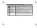
In this manual, the safety instruction levels are classified into "WARNING" and "CAUTION".
WARNING
CAUTION
Denotes that incorrect handling may cause hazardous conditions, resulting in death or severe
injury.
Denotes that incorrect handling may cause hazardous conditions, resulting in medium or slight
injury, or may cause physical damage only.
Note that even the CAUTION level may lead to a serious consequence under some circumstances. Please follow the
instructions of both levels as they are important to personnel safety.
A-1
SAFETY INSTRUCTIONS
1. Electric Shock Prevention
WARNING
z While power is on or when the inverter is running, do not open the front cover. You may get an electric shock.
z Do not run the inverter with the front cover removed. Otherwise, you may access the exposed high-voltage terminals
and charging part and get an electric shock.
z If power is off, do not remove the front cover except for wiring or periodic inspection. You may access the charged
inverter circuits and get an electric shock.
z Before starting wiring or inspection, switch power off, wait for more than 10 minutes, and check for no residual voltage
with a meter etc.
z Any person who is involved in the wiring or inspection of this equipment should be fully competent to do the work.
z Always install the option unit before wiring. Otherwise, you may get an electric shock or be injured.
z Operate the switches with dry hands to prevent an electric shock.
z Do not subject the cables to scratches, excessive stress, heavy loads or pinching. Otherwise, you may get an electric
shock.
z While power is on, do not move the station number and baud rate setting switches. Doing so can cause an electric shock.
2. Injury Prevention
CAUTION
z Apply only the voltage specified in the instruction manual to each terminal to prevent damage, etc.
z Ensure that the cables are connected to the correct terminals. Otherwise, damage, etc. may occur.
z Always make sure that polarity is correct to prevent damage, etc.
z While power is on or for some time after power-off, do not touch the inverter as it is hot and you may get burnt.
A-2
3. Additional instructions
Also note the following points to prevent an accidental failure, injury, electric shock, etc.:
(1) Transportation and installation
CAUTION
z Do not install or operate the option unit if it is damaged or has parts missing.
z Do not stand or rest heavy objects on the product.
z Check that the mounting orientation is correct.
z Prevent screws, metal fragments, conductive bodies or oil, other flammable substance from entering the inverter.
(2) Test operation and adjustment
CAUTION
z Before starting operation, confirm and adjust the parameters. A failure to do so may cause some machines to make
unexpected motions.
(3) Usage
WARNING
z Do not modify the equipment.
A-3
CAUTION
z When parameter clear or all parameter clear is performed, each parameter returns to the factory setting. Re-set the
required parameters before starting operation.
z For prevention of damage due to static electricity, touch nearby metal before touching this product to eliminate static
electricity from your body.
(4) Maintenance, inspection and parts replacement
CAUTION
z Do not test the equipment with a megger (measure insulation resistance).
(5) Disposal
CAUTION
z Dispose of this product as general industrial waste.
(6) General instruction
All illustrations given in this manual may have been drawn with covers or safety guards removed to provide in-depth
description. Before starting operation of the product, always return the covers and guards into original positions as
specified and operate the equipment in accordance with the manual.
A-4
CONTENTS
1 PRE-OPERATION INSTRUCTIONS
1
1.1 Unpacking and Product Confirmation ...................................................................................................................................... 1
1.2 Structure .................................................................................................................................................................................. 2
1.3 Inverter Option (FR-E5NC) Specifications ............................................................................................................................... 3
1.4 CC-Link Ver. 1.10 .................................................................................................................................................................... 4
2 INSTALLATION
5
2.1 Pre-Installation Instructions...................................................................................................................................................... 5
2.2 Installation Procedure .............................................................................................................................................................. 5
2.3 Inverter Replacement............................................................................................................................................................... 7
2.4 System Configuration Example................................................................................................................................................ 8
2.5 Wiring Method.......................................................................................................................................................................... 9
2.6 Connection of Several Inverters............................................................................................................................................. 10
3 INVERTER SETTING
11
3.1 Pre-Operation Setting ............................................................................................................................................................ 11
3.1.1 Inverter station number setting ................................................................................................................................................11
3.1.2 Setting of the transmission baud rate setting switch ................................................................................................................12
3.2 Operation Modes of the Inverter ............................................................................................................................................ 13
3.2.1 Operation mode switching .......................................................................................................................................................13
3.3 Operation at Alarm Occurrence ............................................................................................................................................. 17
3.4 Operation and Speed Command Write.................................................................................................................................. 19
4 FUNCTION OVERVIEW
21
4.1 Function Block Diagram ......................................................................................................................................................... 21
4.2 Setting the Running Frequecy................................................................................................................................................ 22
4.2.1 Monitoring function ..................................................................................................................................................................23
4.2.2 Operation commands ..............................................................................................................................................................24
4.2.3 Running frequency...................................................................................................................................................................24
4.2.4 Parameter write .......................................................................................................................................................................24
4.2.5 Parameter read........................................................................................................................................................................24
5 COMMUNICATION SPECIFICATIONS
25
5.1 I/O Signal List......................................................................................................................................................................... 25
5.1.1 Output signals (master unit → inverter (FR-E5NC)).................................................................................................................25
5.1.2 Input signals (inverter (FR-E5NC) → master unit) ...................................................................................................................28
5.2 Remote Register Assignment ................................................................................................................................................ 30
5.2.1 Remote registers (master unit → inverter (FR-E5NC)) ............................................................................................................30
5.2.2 Remote registers (inverter (FR-E5NC) → master unit) ............................................................................................................31
5.3 Instruction Codes ................................................................................................................................................................... 32
6 PROGRAMMING EXAMPLES
34
6.1 Reply Code Definitions .......................................................................................................................................................... 35
6.2 Program Example for Reading the Inverter Status ................................................................................................................ 36
6.3 Program Example for Setting the Operation Mode ................................................................................................................ 37
6.4 Program Example for Setting the Operation Commands....................................................................................................... 38
6.5 Program Example for Monitoring the Output Frequency........................................................................................................ 39
6.5.1 Monitor codes ..........................................................................................................................................................................40
6.6 Parameter Reading Program Example .................................................................................................................................. 41
6.7 Parameter Writing Program Example .................................................................................................................................... 42
6.8 Running Frequency Setting Program Example ...................................................................................................................... 43
6.9 Alarm Definition Reading Program Example.......................................................................................................................... 45
6.10 Program Example for Resetting the Inverter at Inverter Error.............................................................................................. 47
6.11 Instructions........................................................................................................................................................................... 48
7 HOW TO CHECK FOR ERROR USING THE LEDS
50
7.1 When One Inverter Is Connected .......................................................................................................................................... 50
7.2 When Two or More Inverters Are Connected ........................................................................................................................ 52
7.3 Communication Stops During Operation................................................................................................................................ 54
1 PRE-OPERATION INSTRUCTIONS
PRE-OPERATION INSTRUCTIONS
1 PRE-OPERATION INSTRUCTIONS
1.1 Unpacking and Product Confirmation
Take the option unit out of the package, check the unit name, and confirm that the product is as you ordered and intact.
This product is an inboard option specifically used with the FR-E500 series (FR-E540-0.4K to 7.5K (-NA) (-EC) (-CH),
FR-E520S-0.4K to 2.2K-EC (-CH)).
(1) Packing Confirmation
Make sure that the package includes the following accessories:
· Instruction manual.................................... 1
· Mounting screws M3 × 6.......................... 2
· Operating status LED indication sticker ... 1
(2) Instruction Manual Note
1) Refer to the following manuals for full information on the CC-Link master station:
AJ61BT11/A1SJ61BT11 Control & Communication Link system master/local module user's manual ...........IB-66721
AJ61QBT11/A1SJ61QBT11 Control & Communication Link system master/local module user's manual......IB-66722
QJ61BT11 Control & Communication Link system master/local module user's manual .................................SH-080016
2) In this manual, Control & Communication Link is abbreviated to CC-Link.
1
PRE-OPERATION INSTRUCTIONS
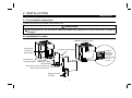
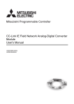
1.2 Structure
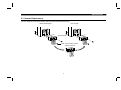
(1) Names and functions
Name
78
78
901
456
456
78
901
L.RUN
SD
RD
L.ERR
456
NC DB DG
DA SLD FG
Terminal block
mounting/
dismounting screw
Operating status
indicator LEDs
Terminal block
mounting/
dismounting screw
Terminal block
screw size M3
2
78
78
456
X1
23
901
X10
23
Mounting hole
Used to set the transmission speed.
For details, refer to page 12.
Operating
status indicator
LEDs
L.RUN ...... Lit to indicate that refresh data is
received properly. Extinguished to
indicate a break in data for a given
period of time.
SD ............ Extinguished to indicate that send
data is "0".
RD............ Lit to indicate that the carrier of
receive data is detected.
L.ERR ...... Lit to indicate the communication
error of the station itself. Flickers to
indicate that the switch or other
setting was changed while power is
on.
SERIAL
FR-E5NC
B.RATE
23
Transmission baud
rate setting switch
×1
Transmission
baud rate
setting switch
SERIAL
Station number
setting switches
901
23
×10
Connector
CC-Link Ver. 1.10
compatibility indication
(Not provided for
incompatible product)
901
23
Station number
setting switches
456
Mounting hole
Function
Used to set the inverter
station number between
1 and 64.
For details, refer to
page 11.
PRE-OPERATION INSTRUCTIONS
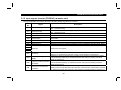
1.3 Inverter Option (FR-E5NC) Specifications
Type
Power supply
Number of units connected
Terminal block
Cable size
Station type
Number of stations occupied
Communication cable
Note:
Inverter inboard option fitted to the terminal block (can be mounted/dismounted to/from
the inverter front face)
5VDC supplied from the inverter
42 units Maximum (1 station occupied by 1 unit). May be used with other equipment.
8-pin terminal block (M3 × 6 screws)
0.75mm2 to 2.00mm2
Remote device station
One inverter occupies one station.
CC-Link dedicated cable, CC-Link Version 1.10 compatible CC-Link dedicated cable
When the CC-Link unit (FR-E5NC) is plugged in, the protective structure (JEM1030) is open type (IP00).
3
PRE-OPERATION INSTRUCTIONS
1.4 CC-Link Ver. 1.10
The conventional CC-Link products, whose inter-station cable lengths have equally been changed to 20cm (7.87 inch) or
more to improve the inter-station cable length restriction, are defined as CC-Link Ver. 1.10. In comparison, the conventional
products are defined as CC-Link Ver. 1.00.
Refer to the CC-Link Master Module Manual for the maximum overall cable lengths and inter-station cable lengths of CC-Link
Ver. 1.00 and Ver. 1.10.
(1) CC-Link Ver. 1.10 compatibility conditions
1) All modules that comprise a CC-Link system should be compatible with CC-Link Ver. 1.10.
2) All data link cables should be CC-Link Ver. 1.10 compatible, CC-Link dedicated cables. (CC-Link Ver. 1.10 compatible
logo or Ver. 1.10 indication.)
cables have a
Note: In a system that uses the CC-Link Ver. 1.00 and Ver. 1.10 modules and cables together, the maximum overall cable
length and inter-station cable length are as specified for CC-Link Ver. 1.00.
(2) How to confirm the CC-Link Ver. 1.10 compatible products
Only the FR-E5NC units manufactured in and after September 2001 are CC-Link Ver. 1.10 compatible.
" or later on its board and shipping carton
1) Product having SERIAL of "B19
(The shipping carton has only three upper digits of the six-digit control number.)
B
Symbol
1
9
Year Month
Control number
SERIAL number
2) Product having a
logo on its board
Refer to page 2 for the SERIAL and logo positions on the board.
4
2 INSTALLATION
INSTALLATION
2 INSTALLATION
2.1 Pre-Installation Instructions
(1) Make sure that the input power of the inverter is off.
CAUTION
With input power on, do not install or remove the option unit. Otherwise, the inverter and option unit may be
damaged.
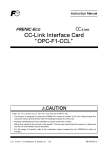
2.2 Installation Procedure
FR-E5NC plugged-in status
Connector for
connection of
inboad option
Accessory screw (2pcs.)
Apply the
operating
status LED
indication
sticker packed
with the
product.
Inboad option
mounting position
CC-Link unit
(FR-E5NC)
Terminal block
Note: The mounting screws do not
release from terminal block.
Wiring port cover
for option
5
INSTALLATION
(1) Remove the front cover and option wiring port cover. (Refer to the inverter manual.)
(2) Remove the sponge from the inboard option connector, align the option unit connector with the inboard option connector
of the inverter, and securely insert it far enough into the inverter.
(3) Securely fix the top and bottom of the option unit to the inverter with the accessory mounting screws. If the screw holes do
not match, check for insecure connector insertion. The connector may not have been inserted securely.
(4) Reinstall the front cover to the inverter. (Refer to the inverter manual.)
Note: 1. While the inboard option is plugged in, store the option wiring port cover carefully.
2. When this option is plugged in, the protective structure of the inverter is the open type (IP00).
3. If the inverter cannot recognize the plugged-in option, the E.OPT error appears. (Refer to the inverter manual.)
6
INSTALLATION
2.3 Inverter Replacement
You can replace the inverter without removing the terminal block wiring.
Before replacement
New inverter
Terminal block
Note: The mounting screws
will not come off.
7
INSTALLATION
2.4 System Configuration Example
(1) PLC side
Load the "AJ61BT11", "A1SJ61BT11", "AJ61QBT11", "A1SJ61QBT11" or "QJ61BT11" "Control & Communication Link
system master/local module" on the main or extension base unit having the PLC CPU used as the master station.
(2) Inverter side
Mount the "CC-Link unit (FR-E5NC)" on the inverter.
(3) Connect the PLC CC-Link unit master station and the FR-E5NC with the CC-Link dedicated cable.
If the cable used is other than the CC-Link dedicated cable, the performance of the CC-Link system is not guaranteed.
For the specifications and availability of the CC-Link dedicated cable, refer to the CC-Link catalog.
Masters for CC-Link master station
CPU
Inverter
Inverter
Master station
Power supply
module
AJ61BT11/A1SJ61BT11 Control &
Communication Link system master/
local module user's manual
... IB-66721
AJ61QBT11/A1SJ61QBT11 Control &
Communication Link system master/
local module user's manual
... IB-66722
QJ61BT11 Control & Communication
Link system master/local module
user's manual
... SH-080016
AJ61
BT11
Up to 42 units
may be connected
when only inverters
are connected
Termination
resistor
Termination
resistor
CC-Link dedicated cable
Power
supply
Motor
8
Power
supply
Motor
INSTALLATION
(4) When the CPU has automatic refresh function (example: QnA series CPU)
Through communication with the corresponding devices using sequence ladder logic, data is automatically transferred to
the refresh buffer of the master station at the execution of the END instruction to perform communication with the remote
devices.
(5) When the CPU does not have automatic refresh function (example: AnA series CPU)
Data is transferred to the refresh buffer of the master station directly by sequence ladder logic to perform communication
with the remote devices.
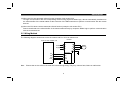
2.5 Wiring Method
The following diagram shows how to wire the inverter and PLC CC-Link master unit:
Inverter
PLC CC-Link master unit
Power
supply
U
S
V
T
W
Motor
FR-E5NC
DA
DB
DG
SLD
FG
DA
DB
DG
SLD
Note:
R
Ensure that no wire offcuts can enter the inverter during wiring. They may cause a fault, failure or malfunction.
9
INSTALLATION
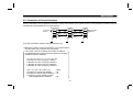
2.6 Connection of Several Inverters
Factory Automation can be applied to several inverters which share a link system as CC-Link remote device stations and are
controlled and monitored by PLC user programs.
Master module
FR-E5NC
FR-E5NC
DA
DA
DA
Termination
resistor*
DB
DB
DB
DG
DG
DG
SLD Shielded twisted SLD Shielded twisted SLD
cable
cable
FG
FG
FG
*Use the termination resistors supplied with the PLC.
1) Maximum number of units connected to one master station
42 units (when only inverters are connected)
If any other units are included, the number of stations
occupied depends on the unit and therefore the following
conditions must be satisfied:
{(1 × a) + (2 × b) + (3 × c) + (4 × d)} ≤ 64
a: Number of units occupying 1 station
b: Number of units occupying 2 stations
c: Number of units occupying 3 stations
d: Number of units occupying 4 stations
{(16 × A) + (54 × B) + (88 × C)}
A: Number of remote I/O stations
B: Number of remote device stations
C: Number of local, standby master
and intelligent device stations
≤ 2304
≤ 64
≤ 42
≤ 26
10
Termination
resistor*
3 INVERTER SETTING
INVERTER SETTING
3 INVERTER SETTING
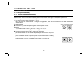
3.1 Pre-Operation Setting
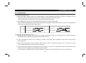
3.1.1 Inverter station number setting
Set the inverter station number before switching on the inverter and do not change the setting while power is on.
When setting the station number, the following points should be taken into consideration:
1) The station number may be set between 1 and 64.
Fully note that if the station number is changed during operation, data communication cannot be made with the new
station number.
Station number setting switches
456
456
×10
×1
Good example Bad example
78
23
78
901
456
901
23
456
11
78
901
23
78
901
23
2) Setting method
z Set the arrow (×) of the corresponding switch to the required numeral.
Example:
y For station number 1: Set (×) of ×10 to "0" and (×) of ×1 to "1".
y For station number 26: Set (×) ×10 to "2" and (×) ×1 to "6".
z Set station numbers consecutively in a connection sequence.
(The station numbers may also be set independently of the connection sequence.)
z Note that the same station number cannot be repeated.
(If the same station number is repeated, proper communication cannot be made.)
z Set each station number switch to the position of its numeral without error. If it is set to any
position between numerals, normal data communication cannot be made.
INVERTER SETTING
3) Connection example
CC-Link
master unit
PLC remote I/O station
(1 station occupied)
Inverter 1
(CC-Link unit)
Remote device station
Station 00
Station 01
Station 02
Inverter 2
(CC-Link unit)
Remote device station
Inverter 3
(CC-Link unit)
Remote device station
Station 03
Station 04
Number of units connected is 4.
Note:
One inverter occupies one station (one remote device station)
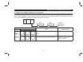
3.1.2 Setting of the transmission baud rate setting switch
Set the transmission speed.
(For details, refer to the CC-Link master unit manual.)
Setting Switch
Transmission Speed
0
156kbps
1
625kbps
2
2.5Mbps
3
5Mbps
4
10Mbps
5 or later should not be used.
(If the switch is set to position 5 or later, the "L.ERR" LED is lit and a communication error occurs.)
12
INVERTER SETTING
3.2 Operation Modes of the Inverter
The inverter mounted with the CC-Link unit (FR-E5NC) has the following operation modes:
(1) PU operation mode ............... Controls the inverter from the keyboard of the operation panel (FR-PA02-02) or parameter
unit (FR-PU04) installed to the inverter.
(2) External operation mode ....... Controls the inverter by switching on/off external signals connected to the control circuit
terminals of the inverter.
(3) CC-Link operation mode ....... Controls the inverter in accordance with the PLC program via the CC-Link unit (FR-E5NC).
3.2.1 Operation mode switching
(1) Operation mode switching conditions
Before switching the operation mode, check that:
1) The inverter is at a stop;
2) Both the forward and reverse rotation signals are off; and
3) The Pr. 79 "operation mode" setting is correct.
(For setting, use the inverter's operation panel or optional parameter unit.)
Pr. 79 Setting
0
1
2
3, 4
6
Operation Mode Selection
PU or external operation
PU operation mode
External operation mode
External/PU combined operation mode
Switch-over
7
External operation (PU operation interlock)
8
PU or external (signal switching)
Switching to CC-Link Operation Mode
Disallowed when the PU mode is selected. Allowed when the
external mode is selected.
Disallowed
Allowed
Disallowed
Allowed
Allowed only in the external operation mode when the output shutoff signal (MRS) is off.
Allowed only in the external operation mode (X16 on).
13
INVERTER SETTING
(2) Operation mode switching method
Change the operation mode as described below:
Switched by
PC program
C
CC-Link
D
External
operation
Switched
from PU
A
PU operation
B
E
(Switching disallowed)
F
Symbol
A
B
C
D
Switching Type
PU operation → External operation
External operation → PU operation
External operation → CC-Link operation
CC-Link operation → External operation
E
PU operation → CC-Link operation
F
CC-Link operation → PU operation
Switching Method
Operate the external operation key on the PU.
Operate the PU operation key on the PU.
By the user program of the PLC.
By the user program of the PLC.
Switching disallowed. Allowed if external operation is selected in A
and CC-Link operation is then selected in C. (Note 2)
Switching disallowed. Allowed if external operation is selected in D
and PU operation is then selected in B. (Note 2)
When "1" is set in Pr. 340 "link start mode selection", the operation mode is CC-Link operation at power on or inverter
reset.
Note: 1. When setting "1" in Pr. 340, the initial settings (station number setting, etc.) of the inverter must be made
without fail.
2. In the switch-over mode (Pr. 79 = 6), switching in E and F is allowed.
14
INVERTER SETTING
(3) Link start mode
The operation mode at power on and at restoration from instantaneous power failure can be selected.
To choose the CC-Link operation mode, set "1" in Pr. 340.
After the link has started, parameter write is enabled with a program. (Refer to page 42 for a parameter write program
example.)
Note: For Pr. 79 "operation mode", different inverters have different functions. For full information, refer to the inverter
manual.
Pr. 340
Setting
0
(Factory
Setting)
Operation Mode
Pr. 79
0
PU or external operation
1
PU operation
2
External operation
3
External/PU combined operation mode
4
External/PU combined operation mode
6
Switch-over mode
7
External operation mode
8
External/PU combined operation mode
Mode at Power On or at Restoration
from Instantaneous Power Failure
Inverter goes into the external operation mode.
Inverter goes into the PU operation mode.
Inverter goes into the external operation mode.
Running frequency is set in the PU operation mode and the start
signal is set in the external operation mode.
Running frequency is set in the external operation mode and the start
signal is set in the PU operation mode.
Operation mode is switched while running.
MRS signal ON....... Shift to the PU operation mode enabled (output
stopped during external operation)
MRS signal OFF..... Shift to the PU operation mode inhibited
X16 signal ON ........ Shift to external operation mode
X16 signal OFF ...... Shift to PU operation mode
15
INVERTER SETTING
Pr. 340
Setting
1
Note:
Pr. 79
Operation Mode
0
PU or CC-Link operation
1
PU operation
2
CC-Link operation
3
CC-Link/PU combined operation mode
4
CC-Link/PU combined operation mode
6
Switch-over mode
7
CC-Link operation mode
8
CC-Link/PU combined operation mode
Mode at Power On or at Restoration
from Instantaneous Power Failure
Inverter goes into the CC-Link operation mode.
(Program need not be used for switching)
Inverter goes into the PU operation mode.
Inverter goes into the CC-Link operation mode.
(Program need not be used for switching)
Running frequency is set in the PU operation mode and the start
signal is set in the CC-Link operation mode.
Running frequency is set in the CC-Link operation mode and the start
signal is set in the PU operation mode.
Inverter goes into the CC-Link operation mode.
Operation mode is switched while running.
MRS signal ON....... Shift to the PU operation mode enabled (output
stopped during CC-Link operation)
MRS signal OFF..... Shift to the PU operation mode inhibited
X16 signal ON ........ Shift to CC-Link operation mode
X16 signal OFF ...... Shift to PU operation mode
The Pr. 340 value may be changed in any operation mode.
16
INVERTER SETTING
3.3 Operation at Alarm Occurrence
Fault Location
Inverter alarm
Communication line alarm
Built-in option alarm
Description
Inverter operation
Data communication
Inverter operation
Data communication
Inverter
Communication
operation
option
Data
connection fault
communication
Inverter
operation
FR-E5NC
alarm
Data
communication
PU operation
Inverter trip
Continued
Continued
Stop
Operation Mode
External operation
Inverter trip
Continued
Continued
Stop
CC-Link operation
Inverter trip
Continued
Inverter trip
Stop
Inverter trip
Inverter trip
Inverter trip
Continued
Continued
Continued
Continued
Continued
Inverter trip
Stop
Stop
Stop
(1) Inverter alarm
Refer to the inverter manual and remove the cause of the alarm.
(2) Communication line alarm
Check the LED states of the FR-E5NC and remove the cause of the alarm. (Refer to page 50.)
Check the CC-Link master station.
The error message "E.OPT" is displayed .
(3) Built-in option alarm
Check the connection between the inverter and FR-E5NC and remove the cause of the alarm.
The error massage "E. 3" is displayed.
17
INVERTER SETTING
(4) Inverter reset (Note 1, 2)
(Refer to page 47 for an inverter reset program example.)
Resetting Method
Inverter reset (*1)
PLC program Instruction code
Error reset at inverter fault (RY1A) (*2)
Connect terminals RES-SD
Switch off inverter power
CC-Link operation
Operation Mode
External operation
PU operation
Allowed
Disallowed
Disallowed
Allowed
Allowed
Allowed
Allowed
Allowed
Allowed
Allowed
Allowed
Allowed
(*1) Inverter reset can be made any time.
(*2) Reset can be made only when the protective function of the inverter is activated.
Note: 1. When a communication line fault has occurred, reset cannot be made from the PLC.
2. The inverter is set to the external operation mode if it has been reset in the CC-Link operation mode.
To resume the CC-Link operation, the inverter must be switched to the CC-Link operation again.
(When "1" is set in Pr. 340 "link start mode selection", switching is not needed. Refer to page 15.)
18
INVERTER SETTING
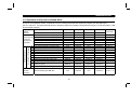
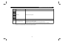
3.4 Operation and Speed Command Write
In the CC-Link operation mode, commands from the external terminals and sequence program are as listed below:
(For Pr. 180 to Pr. 183 (input terminal function selection), different inverters have different functions. For full information, refer
to the inverter manual.)
Control
location
selection
Pr. 338 "operation command write"
0: PLC
Pr. 339 "speed command write"
0: PLC
Pr. 180 to Pr. 183 settings
Selective functions
1: External
1: External
Remarks
Forward rotation command (STF)
Fixed functions Reverse rotation command (STR)
Reset (RES)
(Functions
equivalent to
CC-Link operation frequency
terminals)
2
4
0 Low-speed operation command (RL)
1 Middle-speed operation command (RM)
2 High-speed operation command (RH)
3 Second function selection (RT)
4 Current input selection (AU)
5 Start self-holding selection (STOP)
6 Output shut-off (MRS)
7 External thermal relay input (OH)
8 15-speed selection (REX)
PU operation-external operation
16
switching (X16)
18 Magnetic flux-V/F switching (X18)
RH, RM, RL
selection
functions
0: PLC
Remote setting (RH, RM, RL)
1: External
0: PLC
1: External
PLC
PLC
Both
PLC
PLC
PLC
PLC
PLC
Both
External
PLC
PLC
PLC
Both
External
External
External
External
External
PLC
Both
Both
External
External
External
External
Both
PLC
PLC
PLC
PLC
External
External
External
External
PLC
External
External
Both
External
External
External
External
External
External
Both
External
External
External
External
External
External
External
External
PLC
PLC
External
External
PLC
External
PLC
External
19
Pr. 59 = 0
Pr. 59 = 0
Pr. 59 = 0
(Note)
Pr. 59 = 0
Pr. 59 = 1, 2
INVERTER SETTING
[Explanation of table]
External
: Control by signal from external terminal is only valid.
PLC
: Control from sequence program is only valid.
Both
: Control from both external terminal and PLC is valid.
: Control from both external terminal and PLC is invalid.
Note: When "7" (PU operation interlock function) is set in Pr. 79 "operation mode selection", only the external terminal is
made valid independently of the Pr. 338 and Pr. 339 settings, since this function is also used by terminal MRS.
20
4. FUNCTION OVERVIEW
FUNCTION OVERVIEW
4 FUNCTION OVERVIEW
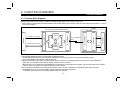
4.1 Function Block Diagram
Using function blocks, this section explains I/O data transfer to/from an inverter in CC-Link:
y Link refresh is continuously executed between the master station and inverter in the CC-Link system at intervals of 1.1ms to
141ms (per station).
Inverter
Buffer
memory
Input
Inverter CPU
CC-Link dedicated
cable
I/O interface
FR-E5NC
CC-Link interface
2) Buffer memory access
CPU
CC-Link interface
PLC CPU
1) AJ61BT11 I/O signals
Interface with PLC
PLC CC-Link system master/local unit
Output
1) I/O signals assigned to the CC-Link system master/local unit.
These signals are used for communication between the PLC CPU and CC-Link system master/local unit.
For further details of the signals, refer to page 25.
2) Allows input data to be read, output data to be written, and a CC-Link faulty station to be read, etc. (The FROM/TO
instruction is not needed when the automatic refresh function is used.)
Buffer memory is accessed by the FROM and TO instructions in the sequence program. For full information on the buffer
memory, refer to the CC-Link system master/local unit manual.
3) CC-Link start is dictated by the sequence program. After CC-Link is initiated, I/O refresh is continually executed
independently of (or in synchronization with) the sequence program execution.
For details, refer to the CC-Link system master/local unit manual.
21
FUNCTION OVERVIEW
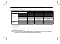
4.2 Setting the Running Frequecy
The following table lists the functions which can be executed from the programmable logic controller in the CC-Link system:
Control Location
User program
Control circuit
terminal
Item
Operation command
Running frequency setting
Monitoring
Parameter write
Parameter read
Inverter reset
Error reset at inverter fault
(RY1A)
Stop command (*2)
Inverter reset terminal
Operation command
Frequency setting
PU operation
Disallowed
Disallowed
Allowed
Disallowed (*3)
Allowed
Disallowed
Operation Mode
External operation
Disallowed
Disallowed
Allowed
Disallowed (*3)
Allowed
Disallowed
CC-Link operation
Allowed
Allowed
Allowed
Allowed (*3)
Allowed
Allowed (*1)
Allowed (*1)
Allowed (*1)
Allowed (*1)
Disallowed
Allowed
Disallowed
Disallowed
Disallowed
Allowed
Allowed
Allowed
Allowed
Allowed
Allowed (*4)
Allowed (*4)
*
( 1) At occurrence of a communication line fault, the inverter cannot be reset from the PLC. (For inverter reset, refer to
the inverter manual.)
( 2) As set in Pr. 75.
( 3) As set in Pr. 77.
Values can be written to Pr. 4 to Pr. 6, Pr. 22, Pr. 24 to Pr. 27, Pr. 52 to Pr. 56, Pr. 72, Pr. 232 to Pr. 239 during
operation.
(For full information, refer to the inverter manual.)
( 4) As set in Pr. 338 and Pr. 339
Note 1. The inverter goes into the external operation mode if it is reset from the PLC in the CC-Link operation mode.
The setting of "1" in Pr. 340 (link start mode) selects CC-Link operation mode.
*
*
*
22
FUNCTION OVERVIEW
4.2.1 Monitoring function
(Refer to page 39.)
The following items can be monitored by the PLC:
1) Output frequency .............. Binary in 0.01Hz increments
2) Output current................... Binary in 0.01A increments
3) Output voltage .................. Binary in 0.1V increments
4) Alarm definition
5) Special monitoring ............ Monitored data selected by instruction code F3H
6) Inverter status
x Overload (OL)
x Forward running
x Frequency detection (FU)
x Reverse running
x Alarm
x Running (RUN)
x Up to frequency (SU)
*
The output signals marked
Note:
*
*
* can be changed using Pr. 190 to Pr. 192 (output terminal function selection).
Items 1) to 4) are read from the buffer memory by setting the corresponding code numbers when needed.
Item 6) can be read from the buffer memory any time.
23
FUNCTION OVERVIEW
4.2.2 Operation commands
(Refer to page 38.)
Any of the following commands can be output from the PLC to the inverter as an operation command any time:
x Middle speed (RM)*1
x Forward rotation (STF)
x Reverse rotation (STR)
x High speed (RH)*1
x Low speed (RL)*1
x Inverter output halt (MRS)*1
The input signals marked *1 can be changed using Pr. 180 to Pr. 183 (input terminal function selection). Depending on the
setting, however, some signals do not accept the command from the PLC. For details, refer to page 19.
4.2.3 Running frequency
(Refer to page 43.)
The running frequency is written from the PLC to the inverter when it is changed......... Binary in 0.01Hz increments
The running frequency may either be written to E2PROM or to RAM. When changing the frequency continuously, always
write the data to the inverter RAM.
4.2.4 Parameter write
(Refer to page 42.)
Functions can be written from the PLC. Note that write during inverter operation will result in a write error.
For the parameter data code list, refer to the inverter manual.
4.2.5 Parameter read
(Refer to page 41.)
Functions can be read to the PLC.
For the parameter data code list, refer to the inverter manual.
24
5. COMMUNICATION SPECIFICATIONS
COMMUNICATION SPECIFICATIONS
5 COMMUNICATION SPECIFICATIONS
5.1 I/O Signal List
The following device No.s are those for station 1.
For stations 2 and later, the device No.s are different. (For the device No. correspondence list, refer to the master unit
manual.)
5.1.1 Output signals (master unit → inverter (FR-E5NC))
The output signals from the master unit are indicated. (Input signals to inverter)
Device
No.
Signal
RY0
Forward rotation command
RY1
Reserve rotation command
RY2
RY3
RY4
RY5
RY6
RY7
RY8
RY9
Description
OFF : Stop command
ON : Forward rotation start (Note 1)
OFF : Stop command
ON : Reserve rotation start (Note 1)
RH terminal function
(high speed)
RM terminal function
(middle speed)
RL terminal function
(low speed)
Functions assigned to RH/RM/RL are selected.
In the factory setting, multi-speed selection can be made by the combination of RH, RM
and RL. (Note 2)
Reserved (Note 5)
Reserved for the system.
Output halt (MRS)
When the MRS signal switches on, the inverter output stops.
Note: 1. Switching on RY0 and RY1 at the same time gives a stop command.
2. With Pr. 180 to Pr. 183 (input terminal function selection), you can set the input signals of device No.s RY2
to RY8. For full information, refer to the inverter manual.
25
COMMUNICATION SPECIFICATIONS
Device
Signal
No.
RYA
Reserved (Note 5)
RYB
RYC
Monitor command
RYD Frequency setting
(Note 4) command (RAM)
RYE Frequency setting
(Note 4) command (E2PROM)
RYF Instruction code execution
(Note 4) request
Description
Reserved for the system.
When the monitor command (RYC) is switched on, the monitored value is set to remote
register RWr0 and monitoring (RXC) switches on. While the monitor command (RYC) is
on, the monitored value is always updated.
When the frequency setting command (RYD) is switched on, the set frequency (RW W1)
is written to the inverter. (Note 3)
On completion of write, frequency setting completion (RXD) switches on.
When the frequency setting command (RYE) is switched on, the set frequency (RW W1)
is written to the inverter.
On completion of write, frequency setting completion (RXE) switches on.
When the instruction code execution request (RYF) is switched on, processing
corresponding to the instruction code set to RW W2 is executed. After completion of
instruction code execution, instruction code execution completion (RXF) switches on.
When an instruction code execution error occurs, a value other than 0 is set to the reply
code (RWr2).
26
COMMUNICATION SPECIFICATIONS
Device
Signal
No.
RY10
RY11
RY12
RY13
RY14
Reserved (Note 5)
RY15
RY16
RY17
RY18
RY19
RY1A
Error reset request flag
Description
Reserved for the system.
If the error reset request flag (RY1A) is switched on only when an inverter fault occurs,
the inverter is reset and the error status flag (RX1A) switches off.
Note: 3. While the set frequency designation (RYD) is on, the set frequency (RW W1) value is always returned.
4. If these commands are switched on simultaneously, only one of these is executed.
5. The reserved input signal should be off. (Enter 0)
27
COMMUNICATION SPECIFICATIONS
5.1.2 Input signals (inverter (FR-E5NC) → master unit)
The input signals to the master unit are indicated. (Output signals from inverter)
Device
No.
Signal
Description
RX0
Forward running
RX1
Reverse running
RX2
RX3
Running (RUN)
Up to frequency (SU)
RX4
Overload (OL)
RX5
RX6
RX7
RX8
RX9
RXA
RXB
Reserved
Frequency detection (FU)
Alarm (A, B, C)
OFF : Other than forward running (during stop or reverse rotation)
ON : Forward running
OFF : Other than reverse running (during stop or forward rotation)
ON : Reverse running
On while the inverter is running. (Note)
Switched on when the output frequency reaches the set frequency ± Pr. 41.
Switched on when stall prevention is activated and switched off when stall prevention is
deactivated.
Reserved for the system.
Switched on when the output frequency reaches the frequency set in Pr. 42. (Note)
Switched on when the inverter's protective function is activated to stop the output. (Note)
Reserved
Reserved for the system.
RXC
Monitoring
RXD
RXE
RXF
Switched on when the monitored value is set to RWr0 by the monitor command (RYC)
switching on. Switched off when the monitor command (RYC) is switched off.
Switched on when the set frequency is written to the inverter by the frequency setting
Frequency setting command
command (RYD) switching on. Switched off when the frequency setting command
(RAM)
(RYD) is switched off.
Switched on when the set frequency is written to the inverter by the frequency setting
Frequency setting command
command (RYE) switching on. Switched off when the frequency setting command
(E2PROM)
(RYE) is switched off.
Switched on on completion of the processing corresponding to the instruction code
Instruction code execution
(RW W2) which is executed when the instruction code execution request (RYF) switches
completion
on. Switched off when the instruction code execution completion (RXF) is switched off.
28
COMMUNICATION SPECIFICATIONS
Device
Signal
No.
RX10
RX11
RX12
RX13
RX14
Reserved
RX15
RX16
RX17
RX18
RX19
RX1A Error status flag
RX1B
Note:
Remote station ready
Description
Reserved for the system.
Switched on when an inverter error occurs (protective function is activated).
Switched on when the inverter goes into the ready status on completion of initial setting
after power-on or hardware reset.
(Used as an interlock for read/write from/to the master station.)
Switched off when an inverter error occurs (protective function is activated).
With Pr. 190 to Pr. 192 (output terminal function selection), you can set the output signals of device No.s RX2,
RX6, RX7. For full information, refer to the inverter manual.
29
COMMUNICATION SPECIFICATIONS
5.2 Remote Register Assignment
5.2.1 Remote registers (master unit → inverter (FR-E5NC))
Device No.
Signal
RW W0
Monitor code
RW W1
Set frequency
RW W2
Instruction code
RW W3
Write data
Addresses
1 station
2 station
1E0H
1E1H
1E2H
1E3H
1E4H
1E5H
1E6H
1E7H
Description
Set the monitor code to be referenced. (Refer to page 40) By switching on the RYC signal
after setting, the specified monitored data is set to RWr0.
Specify the set frequency. At this time, whether it is written to RAM or E2PROM is
differentiated by the RYD and RYE signals. After setting the frequency to this register, switch
on the above RYD or RYE to write the frequency. On completion of frequency write, RXD or
RXE switches on in response to the input command.
Set the instruction code for execution of operation mode rewrite, Pr. read/write, error
reference, error clear, etc. (refer to page 32). The corresponding instruction is executed by
switching on RYF after completion of register setting. RXF switches on on completion of
instruction execution.
Set the data specified by the above instruction code. (When required)
Switch RYF on after setting the above instruction code and this register.
Set zero when the write code is not required.
Remote
Addresses
Registers
RWw0
1E8H
RWw1
1E9H
3 station
RWw2
1EAH
RWw3
1EBH
RWw4
1ECH
RWw5
1EDH
4 station
RWw6
1EEH
RWw7
1EFH
Remote
Addresses
Registers
RWw8
1F0H
RWw9
1F1H
5 station
RWwA
1F2H
RWwB
1F3H
RWwC
1F4H
RWwD
1F5H
6 station
RWwE
1F6H
RWwF
1F7H
30
Remote
Addresses
Registers
RWw10
RWw11
RWw12
RWw13
RWw14
2DCH
RWw15
2DDH
64 station
RWw16
2DEH
RWw17
2DFH
Remote
Registers
RWwFC
RWwFD
RWwFE
RWwFF
COMMUNICATION SPECIFICATIONS
5.2.2 Remote registers (inverter (FR-E5NC) → master unit)
RWr0
Monitored value
The monitored value specified by RW W0 (monitor code) is set.
RWr1
Output frequency
The present output frequency is always set.
RWr2
Reply code
RWr3
Read data
Addresses
1 station
2 station
2E0H
2E1H
2E2H
2E3H
2E4H
2E5H
2E6H
2E7H
The reply code corresponding to RW W2 (instruction code) is set. 0 is set for a normal reply
and a value other than 0 is set for a data error.
For a normal reply, the reply data to the instruction specified by the instruction code is set.
Remote
Addresses
Registers
RWr0
2E8H
RWr1
2E9H
3 station
RWr2
2EAH
RWr3
2EBH
RWr4
2ECH
RWr5
2EDH
4 station
RWr6
2EEH
RWr7
2EFH
Remote
Addresses
Registers
RWr8
2F0H
RWr9
2F1H
5 station
RWrA
2F2H
RWrB
2F3H
RWrC
2F4H
RWrD
2F5H
6 station
RWrE
2F6H
RWrF
2F7H
31
Remote
Addresses
Registers
RWr10
RWr11
RWr12
RWr13
RWr14
3DCH
RWr15
3DDH
64 station
RWr16
3DEH
RWr17
3DFH
Remote
Registers
RWrFC
RWrFD
RWrFE
RWrFF
COMMUNICATION SPECIFICATIONS
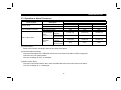
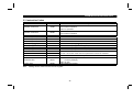
5.3 Instruction Codes
Item
Code Number
Operation mode read
007BH
Operation mode write
00FBH
Alarm history No. 1, No. 2 read
Alarm history No. 3, No. 4 read
Alarm history No. 5, No. 6 read
Alarm history No. 7, No. 8 read
Set frequency (RAM) read
Set frequency (E2PROM) read
Set frequency (RAM) write
Set frequency (E2PROM) write
Parameter read
Parameter write
Batch alarm definition clear
Parameter clear
Inverter reset
Note:
Description
0000H: CC-Link operation
0001H: External operation
0002H: PU operation
0000H: CC-Link operation
0001H: External operation
Reads the most recent No. 1 and 2 alarms.
Reads the most recent No. 3 and 4 alarms.
Reads the most recent No. 5 and 6 alarms.
Reads the most recent No. 7 and 8 alarms.
Reads the set frequency (RAM). (Note)
Reads the set frequency (E2PROM). (Note)
Writes the set frequency to RAM. (Note)
Writes the set frequency to E2PROM. (Note)
0074H
0075H
0076H
0077H
006DH
006EH
00EDH
00EEH
0000H to 006CH Refer to the data code list in the inverter manual, and perform read/write as
0080H to 00ECH required. It should be noted that some parameters cannot be accessed.
00F4H
9696H: Batch-clears the alarm history.
9696H: Parameter clear (parameters values other than calibrated values are reset
00FCH
to factory settings.)
9966H: All clear
00FDH
9696H: Resets the inverter.
Setting can be made from the remote register.
32
COMMUNICATION SPECIFICATIONS
Item
Code Number
Read
007FH
Write
00FFH
Read
006CH
Write
00ECH
Link parameter
expansion setting
Second parameter
changing
Description
Changes the 0000H to 006CH and 0080H to 00ECH parameter values.
0000H: Pr. 0 to Pr. 96
0001H: Pr. 100 to Pr. 156, Pr. 900 to Pr. 905
0002H: Pr. 160 to Pr. 192, Pr. 232 to Pr. 251
0003H: Pr. 338 to Pr. 342
0009H: Pr. 990, Pr. 991
Pr. 902 to Pr. 905
0000H: Offset/gain
0001H: Analog
0002H: Analog value of terminal
33
6. PROGRAMMING EXAMPLES
PROGRAMMING EXAMPLES
6 PROGRAMMING EXAMPLES
This chapter provides programming examples which control the inverter with sequence programs.
6.1
Item
Reply code definitions
6.2
Reading the inverter status
6.3
6.4
6.5
6.6
6.7
Setting the operation mode
Setting the operation commands
Setting the monitoring function
Reading a parameter value
Writing a parameter value
Over of the Functions
"acceleration time"
Reading the alarm definitions
Inverter reset
6.8
6.9
6.10
Program Example
List of codes checked after completion of instruction code execution
Reading the inverter status from the buffer memory of the master
station
Selecting the CC-Link operation mode
Commanding the forward rotation and medium speed signals
Monitoring the output frequency
Reading the value of Pr. 7 "acceleration time"
Setting "3.0s" in Pr. 7 "acceleration time"
36
37
38
39
41
42
Setting to 50.00Hz
43
Reading the inverter alarms
Resetting the inverter
45
47
System configuration for programming example
PLC
Power
supply
Refer to Page
35
X0020
CPU
Master
Input
station
module
(X/Y00 to 1F) (X20 to X2F)
Station 1
Station 2
Inverter
(1 station
occupied)
Inverter
(1 station
occupied)
FR-E5NC
FR-E5NC
34
PROGRAMMING EXAMPLES
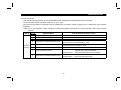
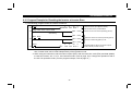
6.1 Reply Code Definitions
When executing the frequency setting (RYD, RYE) or instruction code execution (RYF), check the reply code (RWr2) in the
remote register after execution.
Date
0000H
Item
Normal
0001H
Write error
0002H
0003H
Parameter selection error
Setting range error
Alarm Definition
Normal completion of instruction code execution
Parameter write was attempted during operation other than a stop in the CC-Link
operation mode.
Unregistered code number was set.
Set data is outside the permissible data range.
35
PROGRAMMING EXAMPLES
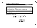
6.2 Program Example for Reading the Inverter Status
Write a program as explained below to read the inverter status from the master station buffer memory:
The following program reads the inverter status of station 1 to M0-M7:
X0000 X000F X0001
H
H
FROM 0000 00E0 D0
MOV D0
Address of master
unit buffer memory
Remote Input
E0H
E1H
E2H
E3H
RXF to RX0
RX1F to RX10
RX2F to RX20
RX3F to RX30
Station 1
Station 2
FROM
instruction
D0
K
1
Reads the remote input data of buffer
memory to D0.
K2
M0
Stores b0-b7 (status) in D0 to M0-M7.
b15 b14 b13 b12 b11 b10 b9 b8 b7 b6 b5 b4 b3 b2 b1 b0
0
0
0
0
* * * *
0
0
[RXF to RX8]
Station 64
0
0
1
1
0
1
[Inverter status]
15EH RX7EF to RX7E0
15FH RX7FF to RX7F0
Up to
Running Forward
frequency
running
MOV instruction
Note:
: Indicates addresses of one inverter.
*: 0 or 1 because of reserved bits
M7 M6 M5 M4 M3 M2 M1 M0
Inverter status
M0: Forward running
M1: Reverse running
M2: Running (RUN)
M3: Up to frequency (SU)
M4: Overload (OL)
M5:
M6: Frequency detection (FU)
M7: Alarm
36
0
0
0
0
1
1
0
1
Inverter status
Example: The above indicates up to
frequency during forward running.
PROGRAMMING EXAMPLES
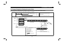
6.3 Program Example for Setting the Operation Mode
Write programs as explained below to write various data to the inverters:
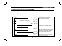
1) The following program changes the operation mode of station 2 inverter to CC-Link operation.
Operation mode writing code number: FBH (hexadecimal)
CC-Link operation set data: 0000H (hexadecimal) (Refer to page 32.)
The reply code at the time of instruction code execution is set to D2. (Refer to page 35.)
M9036
H
H
K4
K
FROM 0000 00E2 M200 2
26
X0000 X000F X0001 X0020 M202
36
M302
Write setting
PLS
M302
SET
M303
Inverter running
44
M303
H
MOV 00FB D100
46
H
MOV 0000 D101
TO
M215
M115
Switches on the instruction code execution
request (RY2F).
K
1
Reads reply code (RWr6) to D2 when the instruction
code execution completion (RX2F) switches on.
RST
M115
Switches off the instruction code execution
request (RY2F).
RST
M303
H
H
FROM 0000 02E6 D2
M9036
88
TO
Writes operation mode writing code (FBH)
to RWw6 and set data (0000H) to RWw7.
H
H
K
0000 01E6 D100 2
SET
67
Reads the remote input (RX20 to RX3F)
data of buffer memory to M200-M231.
H
H
K4
K
0000 0162 M100 2
37
Writes M100-M131 data to the remote outputs
(RY20 to RY3F) of buffer memory.
PROGRAMMING EXAMPLES
6.4 Program Example for Setting the Operation Commands
Write a program as explained below to write the inverter operation commands to the master station buffer memory:
The inverter is operated in accordance with the operation commands written to the remote outputs (addresses 160H to
1DFH).
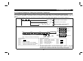
The following program outputs the commands of forward rotation and middle speed signals to the inverter of station 2:
X0000 X000F X0001
26
SET
M100
Forward rotation command (RY20)
SET
M103
Middle-speed command (RY23)
K4
H
H
K
0000 0162 M100 1
TO
Writes the operation commands to buffer
memory and outputs to the inverter.
Address
M115
0
M110
0
0
0
* *
[RY2F to RY2A]
M105
0
0
0
0
0
M100
0
1
0
[Operation commands]
Note: * : Enter 0 since they are reserved bits.
RY2F to RY2A
M110 .....
M111 .....
M112 ..... Monitor command
M113 ..... Frequency setting command (RAM)
M114 ..... Frequency setting command (E 2 PROM)
M115 ..... Instruction code execution request
Middle
speed
0
TO instruction
160H
161H
162H
163H
RY0F to RY00
RY1F to RY10
RY2F to RY20
RY3F to RY30
Station 1
Station 2
1
1: ON
Forward 0: OFF
rotation
Operation commands
M100 ..... Forward rotation command
M101 ..... Reverse rotation command
M102 ..... High speed (RH) *1
M103 ..... Middle speed (RM) *1
M104 ..... Low speed (RL) *1
1DEH RY7EF to RY7E0
1DFH RY7FF to RY7F0
Station 64
M105 .....
M106 .....
M107 .....
M108 .....
M109 ..... MRS
The input signals marked *1 can be changed using Pr. 180 to Pr. 183 (input
terminal function selection). Depending on the setting, however, some signals
do not accept a command from the PLC. Refer to page 19 for details.
38
PROGRAMMING EXAMPLES
6.5 Program Example for Monitoring the Output Frequency
Write programs as explained below to monitor the data of the inverters:
The following program reads the output frequency of station 2 inverter to D1.
Output frequency reading code number: 0001H (hexadecimal)
Example: The output frequency of 60Hz is indicated 1770H (6000).
M9036
H
H
K4
K
FROM 0000 00E2 M200 2
26
X0000 X000F X0001 X0020
H
MOV 0001 D100
36
Read
setting
TO
H
H
K
0000 01E4 D100 1
SET
M212
H
H
FROM 0000 02E4 D1
M9036
65
TO
Switches on the monitor command (RY2C).
K
1
M212: Reads output frequency (RWr4) to D1
when monitoring (RX2C) switches on.
X0000 X000F X0001 X0020
RST
39
Sets the monitor code (01H)
of the output frequency to RWw4.
M112
H
H
K4
K
0000 0162 M100 2
75
Reads the remote input (RX20 to RX3F)
data of buffer memory to M200-M231.
M112
Writes M100-M131 data to the remote
outputs (RY20 to RY3F) of buffer memory.
Monitoring stop.
PROGRAMMING EXAMPLES
6.5.1 Monitor codes
Code Number
0000H
0001H
0002H
0003H
Description
No monitoring (monitored value fixed to 0)
Output frequency (Note)
Output current
Output voltage
Increments
0.01Hz
0.01A
0.1V
Note: About the speed display
When Pr. 37≠0, output frequency monitoring changes to speed monitoring.
Unit for speed display: 1r/min
*Note that the speed display of higher than 65535 (FFFFH) is 65535 (FFFFH).
40
PROGRAMMING EXAMPLES
6.6 Parameter Reading Program Example
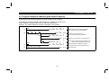
1) The following program reads Pr. 7 "the acceleration time" of station 2 inverter to D1.
Pr. 7 "Acceleration time" reading code number: 07H (hexadecimal)
For the parameter code numbers, refer to the inverter manual.
The reply code at the time of instruction code execution is set to D2. (Refer to page 35.)
M9036
H
H
K
K4
FROM 0000 00E2 M200 2
26
X0000 X000F X0001 X0020
36
M302
PLS
M302
SET
M303
Read setting
43
M303
45
MOV
TO
H
0007 D100
H
H
K
0000 01E6 D100 1
SET
M215
61
Note:
M115
H
H
FROM 0000 02E7 D1
K
1
H
H
FROM 0000 02E6 D2
K
1
M9036
82
Reads the remote input (RX20 to RX3F) data
of buffer memory to M200-M231.
TO
H
H
0000 0162
RST
M115
RST
M303
K4
K
M100 2
Writes Pr. 7 reading code (07H) to RWw6.
Switches on the instruction code execution
request (RY2F).
M215: "Reads acceleration time (RWr7) and reply
code (RWr6) to D1 and D2" when the
instruction code execution completion
(RX2F) switches on.
Switches off the instruction code execution
request (RY2F).
Writes M100-M131 data to the remote outputs
(RY20 to RY2F) of buffer memory.
For parameters having numbers 100 and later, change their link parameter extension settings (set them to
other than 0000H).
41
PROGRAMMING EXAMPLES
6.7 Parameter Writing Program Example
1) Program example which changes the Pr. 7 "acceleration time" setting of station 2 inverter to 3.0s
Acceleration time writing code number: 87H (hexadecimal)
Acceleration time set data: K30 (decimal)
For the parameter code numbers, refer to the inverter manual.
The reply code at the time of instruction code execution is set to D2. (Refer to page 35)
M9036
H
H
K4
K
FROM 0000 00E2 M200 2
26
X0000 X000F X0001 X0020
36
M302
PLS
M302
SET
M303
Write setting
43
M303
H
MOV 0087 D100
45
K
MOV 0030 D101
TO
H
H
K
0000 01E6 D100 2
SET
H
H
FROM 0000 02E6 D2
M115
K
1
M215
M9036
87
Reads the remote input (RX20 to RX3F)
data of buffer memory to M200-M231.
TO
RST
M115
RST
M303
H
H
K4
K
0000 0162 M100 2
Writes Pr. 7 write (87H) to RWw6 and
acceleration time setting data (K30) to RWw7.
Switches on the instruction code execution
request (RY2F).
Reads reply code (RWr6) to D2 when the instruction
code execution completion (RX2F) switches on.
Switches off the instruction code execution
request (RY2F).
Writes M100-M131 data to the remote outputs
(RY20 to RY3F) of buffer memory.
Note: 1. For parameters having numbers 100 and later, change their link parameter extension settings (set them to
other than 0000H).
2. For other functions, refer to the instruction codes (page 32).
42
PROGRAMMING EXAMPLES
6.8 Running Frequency Setting Program Example
1) The following program changes the running frequency of station 2 inverter to 50.00Hz.
Set frequency: K5000 (decimal)
The reply code at the time of instruction code execution is set to D2. (Refer to page 35.)
M9036
H
H
K4
K
FROM 0000 00E2 M200 2
26
X0000 X000F X0001 X0020
36
M302
PLS
M302
SET
M303
Write setting
43
M303
K
MOV 5000 D100
45
TO
H
H
K
0000 01E5 D100 1
SET
M213
66
H
H
FROM 0000 02E6 D2
M9036
82
Reads the remote input (RX20 to RX3F)
data of buffer memory to M200-M231.
TO
M113
Switches on the frequency setting command
RAM (RY2D).
K
1
Reads reply code (RWr6) to D2 when the frequency
setting completion (RX2D) switches on.
RST
M113
Switches off the frequency setting command (RY2D).
RST
M303
H
H
K4
K
0000 0162 M100 2
43
Writes set frequency to RWw5.
Writes M100-M131 data to the remote outputs
(RY20 to RY3F) of buffer memory.
PROGRAMMING EXAMPLES
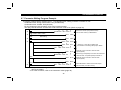
2) To continuously change the running frequency from PLC
When the frequency setting completion (example: RX2D) switches on, make sure that the reply code in the remote
register is 0000H and change the set data (example: RWw5) continuously.
3) Program example for writing data to E2PROM
Modify the above program as follows:
Change the frequency setting command from RY2D to RY2E.
Frequency setting completion RX2D → RX2E
<Timing chart for write to RAM>
RY2D
2
<Timing chart for write to E PROM>
RY2E
(Note 2)
RWW5
RWw5
Inverter
running
frequency
Inverter
running
frequency
(Note1)
Reflected on inverter
at the point when RY2E
switches on
Note: 1. For E2PROM, write is made only once when RY2E is switched on.
2. If the set data is changed with RY2E on, it is not returned on the inverter.
44
PROGRAMMING EXAMPLES
6.9 Alarm Definition Reading Program Example
1) The following program reads the alarm definition of station 2 inverter to D1.
Alarm (error) history No. 1, No. 2 reading code number: 74H (hexadecimal)
The reply code at the time of instruction code execution is set to D2. (Refer to page 35.)
M9036
K4
H
H
K
FROM 0000 00E2 M200 2
26
X0000 X000F X0001 X0020
36
M302
PLS
M302
SET
M303
Read setting
43
M303
H
MOV 0074 D100
45
TO
H
H
K
0000 01E6 D100 1
SET
M215
61
M115
H
H
FROM 0000 02E7 D1
K
1
H
H
FROM 0000 02E6 D2
K
1
M9036
82
Reads the remote input (RX20 to RX3F)
data of buffer memory to M200-M231.
TO
RST
M115
RST
M303
H
H
K4
K
0000 0162 M100 2
45
Writes alarm history No. 1, No. 2 reading
code (74H) to RWw6.
Switches on the instruction code execution
request (RY2F).
Reads alarm data (RWr7) and reply code
(RWr6) to D1 and D2 when the instruction
code execution completion (RX2F) switches on.
Switches off the instruction code execution
request (RY2F).
Writes M100-M131 data to the remote outputs
(RY20 to RY3F) of buffer memory.
PROGRAMMING EXAMPLES
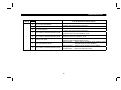
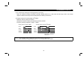
2) Alarm definition display example
Example: Read data is 30A0H
Previous alarm........ THT
Current alarm.......... OPT
b15
b8 b7
0 0 1 1 0 0 0 0 1 0 1 0 0 0 0 0
Previous alarm
(30H)
3) Alarm data
For full information on alarm definition, refer to the inverter manual.
Data
00H
10H
11H
12H
20H
21H
22H
30H
31H
40H
Definition
No alarm
E. OC1
E. OC2
E. OC3
E. OV1
E. OV2
E. OV3
E. THT
E. THM
E. FIN
Data
60H
70H
80H
81H
90H
A0H
B0H
B1H
B2H
F3H
Definition
E. OLT
E. BE
E. GF
E. LF
E. OHT
E. OPT
E. PE
E. PUE
E. RET
E. 3
46
b0
Current alarm
(A0H)
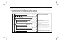
PROGRAMMING EXAMPLES
6.10 Program Example for Resetting the Inverter at Inverter Error
1) The following program resets the inverter of station 2.
M9036
H
H
K4
K
FROM 0000 00E2 M200 2
26
X0000 X000F X0001 M226 X0020
36
SET
M126
SET
M302
RST
M302
RST
M126
Reads the remote input (RX20 to RX3F)
data of buffer memory to M200-M231.
Switches on the error reset request flag (RY1A).
Write setting
M302 M226
46
M9036
50
TO
H
H
K4
K
0000 0162 M100 2
Switches off the error reset request flag (RY1A)
if the error status flag (RX1A) is off.
Writes M100-M131 data to the remote outputs
(RY20 to RY3F) of buffer memory.
Note: 1. The above inverter reset using RY1A may be made only when an inverter error occurs.
Also, inverter reset can be made independently of the operation mode.
2. When using the instruction code execution request (RYF) with the instruction code (FDH) and data (9696H)
to reset the inverter, set "1" in Pr. 340 "link start mode" (refer to page 15) or change the operation mode to
the CC-Link operation mode. (For the program example, refer to page 37.)
47
PROGRAMMING EXAMPLES
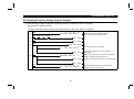
6.11 Instructions
(1) Programming instructions
1) Since the buffer memory data of the master station is kept transferred (refreshed) to/from the inverters, the TO
instruction need not be executed every scan in response to data write or read requests.
The execution of the TO instruction every scan does not pose any problem.
2) If the FROM/TO instruction is executed frequently, data may not be written reliably.
When transferring data between the inverter and sequence program via the buffer memory, perform the handshake to
confirm that data has been written without error.
Correct
TO instruction
Incorrect
TO instruction
Write completion
Write completion
(2) Operating and handling instructions
1) During CC-Link operation, the inverter only accepts commands from the PLC and ignores any external operation
command and any operation command from the parameter unit.
2) If the same station number is set to different inverters, wrong data will be transferred and normal communication
cannot be made.
3) The inverter is brought to any of the alarm stops "E.OPT" if data communication stops, due to a PLC fault, an open
CC-Link dedicated cable etc. during CC-Link operation.
4) If the PLC (master station) is reset during CC-Link operation or if the PLC is powered off, data communication stops
and the inverter is brought to any of the alarm stops "E.OPT".
To reset the PLC (master station), switch the operation mode to the external operation once, then reset the PLC.
48
PROGRAMMING EXAMPLES
5) When the main power of any inverter is restored, that inverter is reset to return to the external operation mode. To
resume the CC-Link operation, therefore, set the operation mode to the CC-Link operation using the PLC program.
Note that setting "1" in Pr. 340 (link start mode) selects the CC-Link operation mode.
(3) Troubleshooting
1) Operation mode does not switch to CC-Link
x Check that the CC-Link units (FR-E5NC) and CC-Link dedicated cables are fitted properly.
(Check for contact fault, open cable, etc.)
x Check that the station number setting switches are set to the correct positions. (Check that the station number
matches the program, the station numbers are not repeated, and the station number is not outside the range.)
x Check that the inverter is in the external operation mode.
x Check that the operation mode switching program is running.
x Check that the operation mode switching program has been written correctly.
2) Inverter does not start in CC-Link operation mode
x Check that the inverter starting program has been written correctly.
x Check that the inverter starting program is running.
x Check that the inverter is providing output.
49
7. HOW TO CHECK FOR ERROR USING THE LEDS
HOW TO CHECK FOR ERROR USING THE LEDS
7 HOW TO CHECK FOR ERROR USING THE LEDS
7.1 When One Inverter Is Connected
The following example indicates the causes of faults which may be judged from the LED states of the CC-Link unit (FRE5NC) of the inverter under the condition that the SW, M/S and PRM LEDs of the master unit are off (the master unit setting
is correct) in a system configuration where one inverter is connected:
Power
supply
CPU
Master
unit
Station 1
Inverter
50
HOW TO CHECK FOR ERROR USING THE LEDS
{
{
{
{
{
LED Status
SD
RD
~
~
~
~
~
{
~
{
{
~
{
~
{
{
{
{
~
~
~
~
~
{
~
{
{
~
{
{
~
{
{
{
{
{
{
{
~
{
{
{
~{
~
{
~
{
L. RUN
z
z
z
z
z
z
z
z
z
{
Cause
L. ERR
~
{
~
{
~
{
~
{
~
{
~
{
~
z
~
z
Normal communication is made but CRC error has occurred due to noise.
Normal communication
Hardware fault
Hardware fault
Cannot answer due to CRC error of receive data.
Data sent to the host station does not reach destination.
Hardware fault
Hardware fault
Polling response is made but refresh receive is in CRC error.
Hardware fault
Hardware fault
Hardware fault
Data sent to the host station is in CRC error.
There is no data sent to the host station, or data sent to the host station cannot be
received due to noise.
Hardware fault
Cannot receive data due to open cable, etc.
Invalid baud rate or station number setting
Baud rate or station number changed during operation.
WDT error occurrence (hardware fault), power off, power supply failure
z: On, {: Off, ~: Flicker
51
HOW TO CHECK FOR ERROR USING THE LEDS
7.2 When Two or More Inverters Are Connected
The following example indicates the causes and corrective actions for faults which may be judged from the LED states of the
CC-Link units (FR-E5NCs) of the inverters under the condition that the SW, M/S and PRM LEDs of the master unit are off
(the master unit setting is proper) in the system configuration shown below:
Power
supply
Master
unit
TIME
LINE
or
TIME
LINE
{
{
z
{
CPU
Master
unit
Station 1
Station 2
Station 3
Inverter A
Inverter B
Inverter C
LED States
Inverters (FR-E5NC)
Cause
Station 1 Station 2 Station 3
L. RUN z L. RUN z L. RUN z
z SD
z SD
z
SD
Normal
z RD
z RD
z
RD
L. ERR { L. ERR { L. ERR {
L. RUN { L. RUN z L. RUN z
{ SD
z SD
z
SD
Poor contact of the FR-E5NC with the inverter
{ RD
z RD
z
RD
L. ERR { L. ERR { L. ERR {
52
Corrective Action
Plug the FR-E5NC securely.
Check the connector.
HOW TO CHECK FOR ERROR USING THE LEDS
Master
unit
TIME
LINE
or
TIME
LINE
{
{
z
{
LED States
Inverters (FR-E5NC)
Station 1 Station 2 Station 3
L. RUN z L. RUN { L. RUN {
z SD
SD
SD
z RD
RD
RD
L. ERR { L. ERR { L. ERR {
L. RUN { L. RUN { L. RUN {
SD
SD
SD
RD
RD
RD
L. ERR { L. ERR { L. ERR {
L. RUN { L. RUN { L. RUN {
SD
SD
SD
RD
RD
RD
L. ERR
L. ERR
L. ERR
Cause
Corrective Action
*
*
*
*
Since the L.RUN LEDs of the FR-E5NCs on
Referring to the LED "on"
station 2 and later are off, the transmission cable
condition, search for an open point
between the remote I/O units A and B is open or
and repair.
disconnected from the terminal block.
*
*
*
*
*
*
The transmission cable is shorted.
Among the three wires of the
transmission cable, search for the
shorted wire and repair.
*
*
*
*
*
*
*
*
*
The transmission cable is wired improperly.
Check the wiring on the inverter
terminal block and correct the
improper wiring point.
z: On, {: Off, ~: Flicker, *: Any of on, flicker or off
53
HOW TO CHECK FOR ERROR USING THE LEDS
7.3 Communication Stops During Operation
x Check that the CC-Link unit (FR-E5NC) and CC-Link dedicated cables are fitted properly. (Check for contact fault, open
cable, etc.)
x Check that the programmable controller program is executing properly.
x Check that data communication has not stopped due to an instantaneous power failure, etc.
Master
unit
LED States
Inverters (FR-E5NC)
Station 1 Station 2 Station 3
L. RUN { L. RUN z L. RUN {
z SD
SD
SD
z RD
z RD
z
RD
L. ERR { L. ERR { L. ERR {
L. RUN z L. RUN { L. RUN z
{ SD
z SD
z
SD
z RD
z RD
z
RD
L. ERR { L. ERR { L. ERR {
L. RUN z L. RUN z L. RUN z
z SD
z SD
z
SD
z RD
z RD
z
RD
L. ERR { L. ERR { L. ERR ~
*
TIME
LINE
or
TIME
LINE
{
{
z
{
L. RUN
SD
RD
L. ERR
{ L. RUN
{ SD
z RD
z L. ERR
*
z L. RUN z
z SD
z
z RD
z
{ L. ERR {
Cause
Since the L.RUN LEDs of the FR-E5NC on
station 1 and the FR-E5NC on station 3 are off,
the station numbers of the inverters set as
stations 1 and 3 are the same.
Since the L.RUN and SD LEDs of the FR-E5NC
on station 2 are off, the transmission speed
setting of the FR-E5NC on station 2 is wrong
within the setting range (0 to 4).
Corrective Action
After correcting the repeated
station numbers of the inverters,
switch power on again.
After correcting the transmission
speed setting, switch power on
again.
After returning the setting switch of
Since the L.ERR LED of the FR-E5NC on station
the FR-E5NC to the original
3 flickers, the setting switch of the FR-E5NC on
position, power on the inverter
station 3 was moved during normal operation.
again.
Since the L.RUN and SD LEDs of the FR-E5NC
on station 1 are off and its L.ERR LED is on, the After correcting the setting switch
setting switch setting of the FR-E5NC on station position of the FR-E5NC, switch
1 is outside the range (transmission speed: 5 to power on again.
9, station number: 65 or more).
54
HOW TO CHECK FOR ERROR USING THE LEDS
Master
unit
TIME
LINE
or
TIME
LINE
z
z
{
z
LED States
Inverters (FR-E5NC)
Station 1 Station 2 Station 3
L. RUN z L. RUN z L. RUN z
z SD
z SD
z
SD
z RD
z RD
z
RD
L. ERR { L. ERR z L. ERR {
L. RUN z L. RUN z L. RUN z
z SD
z SD
z
SD
z RD
z RD
z
RD
L. ERR { L. ERR z L. ERR z
L. RUN z L. RUN z L. RUN z
z SD
z SD
z
SD
z RD
z RD
z
RD
L. ERR { L. ERR { L. ERR z
Cause
Corrective Action
Since the L.ERR LED of the FR-E5NC on station
Securely connect FG of each
2 is on, the FR-E5NC itself on station 2 is
inverter and master unit to ground.
affected by noise. (L.RUN may go off.)
Since the L.ERR LEDs of the FR-E5NCs on
station 2 and later are on, the transmission cable
between the inverters of stations 2 and 3 is
affected by noise. (L.RUN may go off.)
Check that the transmission cable
is connected to SLD. Also run it as
far away as possible from the
power lines. (100mm or more)
Terminal resistors are left unconnected. (L.RUN
may go off.)
Check that the terminal resistors
are connected.
z: On, {: Off, ~: Flicker, *: Any of on, flicker or off
55
REVISIONS
*The manual number is given on the bottom left of the back cover.
Print Date
*Manual Number
Jul., 1999
Aug., 2001
IB(NA)-0600003-A
IB(NA)-0600003-B
Revision
First edition
Partial changes
• Program examples
Additions
• CC-Link Ver. 1.10 specifications
• Applicable Control & Communication Link system master/local modules