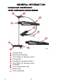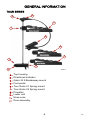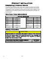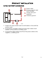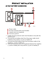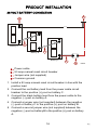
1
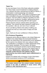
90-8M4002702 111
Tour Series
Thank You
Thank you for choosing MotorGuide® Tour Series.
MotorGuide capitalized on many years of experience to
provide you with a motor designed to deliver Digital Variable
Speed Control and maximum time on the water.
The Tour Series was designed with quality and durability in
mind. The all‑metal construction provides years of reliability
with unmatched control and feel. The stainless steel cables
and pulleys allow you to concentrate less on boat control and
more on fishing. Couple these mechanics with MotorGuide
Digital electronics, and you have one of the most popular
trolling motors in the fishing world.
Through the alliance between MotorGuide and Lowrance, we
have codeveloped one of the quietest, most accurate
transducer integrated trolling motors ever built. The 200/83
kHz transducer provides an accurate sonar plot and a
responsive temperature reading. This combination is sure to
improve your fishing, season after season.
Remember to keep your receipt and immediately register your
trolling motor. A warranty card is enclosed or you can
complete registration on the internet at www.motorguide.com.
At MotorGuide, we believe there are some things you should
Never Stop doing.
Warranty Message
The product you purchased comes with a Limited Warranty
from MotorGuide. The terms of the policy are set forth in the
Warranty Information section of this manual. The policy
statement contains a description of the duration of coverage,
important disclaimers and limitations of damages, and
other related information. Please review this important
information.
eng
i
© 2010 Mercury Marine
NEVER STOP LEARNING, NEVER STOP IMPROVING,
AND NEVER, EVER STOP FISHING.
The description and specifications contained herein were in effect
at the time this manual was approved for printing. MotorGuide,
whose policy is one of continued improvement, reserves the right
to discontinue models at any time, to change specifications,
designs, methods, or procedures without notice and without
incurring obligation.
MotorGuide, Lowell, Michigan U.S.A.
Litho in U.S.A.
© 2010, Mercury Marine. All Rights Reserved. Reproduction in
whole or in part without permission is prohibited.
Safari is a trademark of Brunswick Corporation.
Mercury, Mercury Marine, MerCruiser, Mercury MerCruiser,
Mercury Racing, MotorGuide, Gator, Machete, Mercury Precision
Parts, Mercury Propellers, Mariner, Quicksilver, #1 On The Water,
Alpha, Bravo, Bravo Two, Pro Max, OptiMax, Sport‑Jet, K‑Planes,
MerCathode, SmartCraft, Total Command, VesselView, Zero
Effort, Zeus, M with Waves logo, Mercury with Waves logo, and
SmartCraft logo are all registered trademarks of Brunswick
Corporation. Mercury Product Protection logo is a registered
service mark of Brunswick Corporation.
Lowrance is a registered trademark of Navico Inc. Garmin is a
registered trademark of Garmin Ltd. Vexilar is a registered
trademark of Vexilar, Inc.
ii
eng
Warranty Information
MotorGuide Limited Warranty......................................................1
General Information
Component Identification.............................................................5
Recording Serial Number............................................................7
Boater's Responsibilities..............................................................7
Safe Boating Suggestions...........................................................8
Product Installation
Tour Gator 21 Spring Mount Installation......................................9
Foot Pedal Permanent Installation............................................. 10
Standard Practices and Procedures..........................................11
Battery Recommendations........................................................11
Battery Precautions...................................................................12
Wire and Cable Routing............................................................. 12
Establishing A Common Ground...............................................13
Wire Color Code Abbreviations.................................................13
Battery Connection....................................................................13
Trolling Motor Operation
Installing and Removing the Motor............................................17
Connecting the Sonar Display to Motor.....................................17
Stowing and Deploying the Trolling Motor.................................18
Adjusting the Motor Depth.........................................................20
Foot Pedal Operation................................................................. 22
eng
iii
Maintenance and Storage
Trolling Motor Care....................................................................24
Inspection and Maintenance Schedule......................................24
Storage Preparation................................................................... 25
Battery Inspection......................................................................26
Propeller Replacement..............................................................26
Foot Pedal Cable Tension Adjustment......................................27
Owner Service Assistance
Troubleshooting.........................................................................29
Service Assistance....................................................................32
Mercury Marine Service Offices.................................................33
iv
eng
WARRANTY INFORMATION
MotorGuide Limited Warranty
KEEP YOUR ORIGINAL PURCHASE RECEIPT OR BILL OF
SALE.
1. For recreational use customers, MotorGuide electric trolling
motors are warranted to the original retail purchaser to be free
from defects in material or workmanship for two (2) years.
2. To obtain warranty service, the purchaser should deliver or
return the unit (postage prepaid and insured) to any
authorized MotorGuide service dealer. DO NOT RETURN TO
PLACE OF PURCHASE unless they are an authorized service
center. Products returned by mail should be carefully
packaged and include a note describing the nature of the
problem and/or service requested, customer address, and
phone number. A copy of the receipt, Bill of Sale, registration
verification or other proof of purchase is required with the
return of the product for warranty consideration. Warranty
claims will not be accepted without presentation of purchase
receipt for trolling motor, other verification of registration, or
Bill of Sale for boat package.
3. MotorGuide, at its discretion, will repair or replace items
covered under the terms of this warranty. Neither MotorGuide
nor MotorGuide service dealers are responsible for damages
to MotorGuide products due to repairs performed by anyone
other than an authorized MotorGuide service dealer. Neither
MotorGuide nor Mercury Marine is responsible for failure or
damage caused by improper installation, setup, preparation,
or previous service or repair errors.
eng
1
WARRANTY INFORMATION
4. For commercial use and government use customers,
MotorGuide electric trolling motors are warranted to the
original retail purchaser to be free from defects in material or
workmanship for one (1) year. Commercial use is defined as
any work or employment‑related use of the product, or any
use of the product which generates income, for any part of the
warranty period, even if the product is only occasionally used
for such purpose such as Rental Fleets, Guides, Fish Camps
or similar operations. Warranty is not transferable to any
subsequent purchaser. The Mercury Product Protection plan
is not available to commercial use or government use
customers.
5. Warranty coverage is available to customers that purchase
from an authorized dealer or retailer that is authorized by
MotorGuide Marine to distribute the product in the country in
which the sale occurred. Warranty coverage and duration
varies by the country in which the owner resides. This
warranty applies to MotorGuide trolling motors sold and used
in the United States. This Limited Warranty begins on the date
the product is first sold to a purchaser or the date on which the
product is first put into service, whichever occurs first.
MotorGuide accessories are covered by this Limited Warranty
for a coverage period of one (1) year from the date of retail
sale. The repair or replacement of parts, or the performance
of service under this warranty, does not extend the life of this
warranty beyond its original expiration date. Promotional
warranties are not included in this statement and coverage
may vary by promotion. Product either sold or put into service
more than six years from date of manufacture is excluded from
warranty coverage.
2
eng
WARRANTY INFORMATION
6. This warranty does not apply to normal worn parts, for
example, worn cables, adjustments, or product damage due
to; 1) neglect, lack of maintenance, accident, abnormal
operation or improper installation or service; 2) abuse, such
as, bent metal columns, bent armature shafts, broken control
cables, etc., accidents, modifications, misuse, excessive wear
or damage caused by an owner’s failure to provide reasonable
and necessary installation or care; 3) use of an accessory or
part not manufactured by MotorGuide or Mercury; 4) alteration
or removal of parts; 5) opening the lower unit (motor) by
anyone other than an authorized MotorGuide service center
will void this warranty.
7. We reserve the right to improve the design of any trolling motor
without assuming any obligation to modify any trolling motor
previously manufactured.
8. All serialized "Service‑Repair" trolling motors receive a one (1)
year warranty. Nonserialized "Service‑Repair" electric trolling
motors are NOT warranted. "Service‑Repair" motor denotes
a trolling motor sold by MotorGuide that may be used but has
been inspected and may have had minor repairs. Original
retail purchaser of a "Service‑Repair" motor is the first
purchaser of the motor after it is denoted as "Service‑Repair."
"Service‑Repair" motors have a blue sticker on the battery
cable and box denoting "Manufacturer Certified
Service‑Repair Motor."
9. This warranty will not apply to 1) haul‑out, launch, towing and
storage, transportation charges and/or travel time, telephone
or rental charges of any type, inconvenience, or loss of time
or income, or other consequential damages; or 2) removal or
replacement of boat partitions or material because of boat
design for necessary access to the Product; or 3)
disconnection and reconnection of hard‑wired trolling motors.
10. TERMINATION OF COVERAGE: Warranty coverage may be
terminated for repossessed product, or product purchased at
auction, from a salvage yard, from a liquidator, from an
insurance company, from unauthorized marine dealers or
boatbuilders, or other third party entities.
eng
3
WARRANTY INFORMATION
11. ALL INCIDENTAL OR CONSEQUENTIAL DAMAGES ARE
EXCLUDED FROM THIS WARRANTY, WARRANTIES OF
MERCHANTABILITY AND FITNESS ARE EXCLUDED
FROM THIS WARRANTY, IMPLIED WARRANTIES ARE
LIMITED TO THE LIFE OF THIS WARRANTY. SOME
STATES DO NOT ALLOW LIMITATIONS ON HOW LONG
AN IMPLIED WARRANTY LASTS OR THE EXCLUSION OR
LIMITATION OF INCIDENTAL OR CONSEQUENTIAL
DAMAGES, SO THE ABOVE LIMITATIONS OR
EXCLUSIONS MAY NOT APPLY TO YOU. THIS
WARRANTY GIVES YOU SPECIFIC LEGAL RIGHTS, AND
YOU MAY ALSO HAVE OTHER LEGAL RIGHTS WHICH
MAY VARY FROM STATE TO STATE.
For your records:
Model Number _______________________________
Serial Number _______________________________
4
eng
GENERAL INFORMATION
Component Identification
TOUR LOWRANCE SONAR SERIES
a
b
c
j
d
e
f
i
g
h
abcdefghij-
eng
46022
Top housing
Directional indicator
Tour Gator 21 Spring mount
Foot pedal
Lowrance connector cable
Tour Gator 24 Spring mount
Propeller
Tour Sonar lower unit
Nose cone
Door assembly
5
GENERAL INFORMATION
TOUR SERIES
a
b
c
j
d
e
f
i
g
h
46023
abcdefghij-
Top housing
Directional indicator
Gator 20.8 Breakaway mount
Foot pedal
Tour Gator 21 Spring mount
Tour Gator 24 Spring mount
Propeller
Lower unit
Nose cone
Door assembly
6
eng
GENERAL INFORMATION
Recording Serial Number
Record the serial number for future reference. For warranty
purposes, complete the enclosed warranty card or register your
trolling motor at www.motorguide.com.
a
b
c
b
a
45938
a - Serial number
b - Model identification number
c - Voltage
Boater's Responsibilities
The operator (driver) is responsible for the correct and safe
operation of the boat and safety of its occupants and general
public. It is strongly recommended that each operator (driver) read
and understand this entire manual before operating the trolling
motor.
Be sure at least one additional person on board is instructed in the
basic operation of the trolling motor in case the driver is unable to
operate the boat.
eng
7
GENERAL INFORMATION
Safe Boating Suggestions
In order to safely enjoy the waterways, familiarize yourself with
local and other governmental boating regulations and restrictions,
and consider the following suggestions.
Use flotation devices. It is the law to have an approved personal
flotation device of suitable size for each person aboard and have
it readily accessible.
Do not overload your boat. Most boats are rated and certified for
maximum load (weight) capacities, refer to your boat capacity
plate. If in doubt, contact your dealer or the boat's manufacturer.
Perform safety checks and required maintenance. Follow a regular
schedule and ensure all repairs are made properly.
Never be under the influence of alcohol or drugs while boating (it
is the law). Alcohol or drug use impairs your judgment and greatly
reduces your ability to react quickly.
Passenger boarding. Stop the trolling motor whenever passengers
are boarding or unloading.
Be alert. The operator of the boat is responsible by law to maintain
a proper lookout by sight and hearing. The operator must have an
unobstructed view particularly to the front. No passengers, load,
or fishing seats should block the operators view when operating
the boat.
Underwater hazards. Reduce speed and proceed with caution
whenever navigating in shallow water.
Tripping hazards. To avoid a trip hazard, route all cables and
wiring neatly and out of the way.
Report accidents. Boat operators are required by law to file a
Boating Accident Report with their state boating law enforcement
agency when their boat is involved in certain boating accidents. A
boating accident must be reported if 1) there is loss of life or
probable loss of life, 2) there is personal injury requiring medical
treatment beyond first aid, 3) there is damage to boats or other
property where the damage value exceeds $500.00 or 4) there is
complete loss of the boat. Seek further assistance from local law
enforcement.
8
eng
PRODUCT INSTALLATION
Tour Gator 21 Spring Mount Installation
NOTE: This bow mount installation procedure applies to the Gator
20.8 Breakaway mount (pictured), the Tour Gator 21 Spring mount,
and the Tour Gator 24 Spring XL mount.
IMPORTANT: Choose an area on the deck that provides 7.6 cm
(3 in.) clearance from the bow of the boat for all motor positions,
including deployed and stowed positions.
1. Select an appropriate area on the deck of the boat to install
the mount. Ensure the forward mounting screws will not
penetrate the hull.
41280
Mount on deck with a 7.6 cm (3 in.) clearance
2. Place the bow mount base on the surface of the boat deck.
Use the bow mount base as a template to mark the locations
of the front mounting holes in the plastic decket and the rear
mounting holes on the mount base.
38097
Mount base mounting holes
eng
9
PRODUCT INSTALLATION
3. Drill the mounting holes with a 7 mm (1/4 in.) diameter drill bit.
Remove any debris.
4. Redrill each mounting hole with a 13 mm (1/2 in.) diameter drill
bit.
IMPORTANT: Countersink the holes on fiberglass boats to
prevent cracking.
5. Insert the rubber mounting isolators into the drilled holes.
Position the isolators in line with the mount base with the wider
side toward the outside of the mount bracket.
39076
6. Place the mount bracket on the isolators and align the holes.
Install the two long screws into the front mounting holes and
the two short screws into the rear mounting holes. Tighten all
of the mounting screws securely with a Phillips screwdriver.
Do not tighten the mounting screws with an electric driver.
IMPORTANT: The bracket must lay flush against the isolators
before being bolted to the deck or the mount will bind, making it
difficult or impossible to unlatch.
7. When the bracket is installed, it should fasten securely and
evenly with the latch pins and release with a light, quick, pull
of the rope handle.
Foot Pedal Permanent Installation
NOTE: It is not necessary to permanently mount the foot pedal to
operate the trolling motor.
1. Select an appropriate area on the deck of the boat to install
the foot pedal.
2. Place the foot pedal on the surface of the boat deck. Use the
foot pedal as a template to mark the locations of the mounting
holes on the boat deck.
10
eng
PRODUCT INSTALLATION
3. Drill the mounting holes with a 3 mm (7/64 in.) diameter drill
bit. Remove any debris.
4. Use four 8 x 2 in. stainless steel screws to secure the foot
pedal base to the boat deck.
41447
Foot pedal mounting holes and screws
Standard Practices and Procedures
•
•
•
•
Do not use the main engine battery to power the trolling motor.
Disconnect the trolling motor from the battery when charging
and after each use.
Route the trolling motor wires on the opposite side of the boat
from other miscellaneous boat wiring.
Connect boat accessories directly to the main engine battery.
Battery Recommendations
•
Use a 12 volt, deep cycle marine battery. Refer to Battery
Connection.
•
Install a 50 amp manual reset circuit breaker in line with the
trolling motor positive leads within 180 cm (72 in.) of the
batteries.
Use 13 mm (6 gauge) battery cables if extending the existing
wire 3 m (10 ft) beyond the standard battery cable supplied
with the product.
•
eng
11
PRODUCT INSTALLATION
Recommended MotorGuide Accessory Description
50 Amp Manual Reset Circuit Breaker
Part Number
MM5870
Battery Precautions
! WARNING
An operating or charging battery produces gas that can ignite and
explode, spraying out sulfuric acid, which can cause severe
burns. Ventilate the area around the battery and wear protective
equipment when handling or servicing batteries.
When charging batteries, an explosive gas mixture forms in each
cell. Part of this gas escapes through holes in the vent plugs and
may form an explosive atmosphere around the battery if ventilation
is poor. This explosive gas may remain in or around the battery for
several hours after it has been charged. Sparks or flames can
ignite this gas and cause an internal explosion, which may shatter
the battery.
The following precautions should be observed to prevent an
explosion:
1. Do not smoke near batteries being charged or which have
been charged very recently.
2. Do not break live circuits at terminals of batteries, because a
spark usually occurs at the point where a live circuit is broken.
Always be careful when connecting or disconnecting cable
clamps on chargers. Poor connections are a common cause
of electrical arcs which cause explosions.
3. Do not reverse polarity of battery terminal to cable
connections.
Wire and Cable Routing
•
•
Route the trolling motor wires on the opposite side of the boat
from other boat wiring.
Accessories should be connected directly to the main engine
battery.
12
eng
PRODUCT INSTALLATION
Establishing A Common Ground
Connect the trolling motor and main engine accessories to the
same negative ground terminal. A common ground connection
increases sonar sensitivity and improves the sonar display. Not
establishing a common ground may cause severe corrosion or
electrolysis.
Wire Color Code Abbreviations
Wire Color Abbreviations
BLK
Black
BLU
Blue
BRN
Brown
GRY
Gray
GRN
Green
ORN or ORG
Orange
PNK
Pink
PPL or PUR
Purple
RED
Red
TAN
Tan
WHT
White
YEL
Yellow
LT or LIT
Light
DK or DRK
Dark
Battery Connection
! CAUTION
Disconnecting or connecting the battery cables in the incorrect
order can cause injury from electrical shock or can damage the
electrical system. Always disconnect the negative (‑) battery
cable first and connect it last.
Recommended MotorGuide Accessory Description
50 Amp Manual Reset Circuit Breaker
eng
13
Part Number
MM5870
PRODUCT INSTALLATION
12 VOLT BATTERY CONNECTION
a
a - Power cable
b - 50 amp manual reset
circuit breaker
c - Jumper wire (not
supplied)
d - Common ground
d
RED
BLK
c
b
37289
1. Install a 50 amp manual reset circuit breaker in line with the
positive lead.
2. Connect the red battery lead from the power cable circuit
breaker to the positive (+) battery post.
3. Connect the black battery lead from the power cable to the
negative (–) battery post.
14
eng
PRODUCT INSTALLATION
24 VOLT BATTERY CONNECTION
a
d
BLK
RED
A
GR
Battery A
c
Battery B
abcd-
c
b
37824
Power cable
50 amp manual reset circuit breaker
Jumper wire (not supplied)
Common ground
1. Install a 50 amp manual reset circuit breaker in line with the
positive lead.
2. Connect the red battery lead from the power cable circuit
breaker to the positive (+) post on battery B.
3. Connect the black battery lead from the power cable to the
negative (–) post on battery A.
4. Connect the jumper wire (not supplied) between the negative
(–) post on battery B to the positive (+) post on battery A.
eng
15
PRODUCT INSTALLATION
36 VOLT BATTERY CONNECTION
a
d
BLK
A
GR
c
A
GR
RED
Battery A
Battery B
c
Battery C
abcd-
c
b
45996
Power cable
50 amp manual reset circuit breaker
Jumper wire (not supplied)
Common ground
1. Install a 50 amp manual reset circuit breaker in line with the
positive lead.
2. Connect the red battery lead from the power cable circuit
breaker to the positive (+) post on battery C.
3. Connect the black battery lead from the power cable to the
negative (–) post on battery A.
4. Connect a jumper wire (not supplied) between the negative
(–) post on battery C to the positive (+) post on battery B.
5. Connect a second jumper wire (not supplied) between the
negative (–) post on battery B to the positive (+) post on battery
A.
16
eng
TROLLING MOTOR OPERATION
Installing and Removing the Motor
41286
Bracket knob
1. To install the motor to the bow mount, turn the bracket knob
counterclockwise to loosen and open the bracket door.
2. Place the motor column into the bracket and close the door.
3. Turn the bracket knob clockwise to tighten the motor column
in the bracket.
REMOVING THE MOTOR
1. To remove the motor from the bow mount, turn the bracket
knob counterclockwise to loosen and open the bracket door.
2. Remove the motor column from the bracket and close the
door.
Connecting the Sonar Display to Motor
NOTE: This sonar display connection procedure applies to the
Tour Series motors that offer built‑in 200/83 kHz sonar transducers
compatible with Eagle®, Garmin®, Humminbird®, Lowrance®, and
Vexilar® brand sonar displays. Tour sonar models connect with
Lowrance 7 pin sonar units. For compatibility with other sonar
units, refer to www.motorguide.com.
eng
17
TROLLING MOTOR OPERATION
Match the cable connector to the sonar port on the back of the
sonar display. Power up the unit to ensure the sonar cable is
connected securely.
41478
Lowrance 7 pin sonar connector
Stowing and Deploying the Trolling Motor
! WARNING
Rotating propellers can cause serious injury or death. Never start
or operate the motor out of water.
! CAUTION
Moving parts, such as hinges and pivot points, can cause serious
injury. Keep away from moving parts when stowing, deploying,
or tilting the motor.
NOTE: The bow mount stowing and deploying procedures apply
to the Gator 20.8 Breakaway mount (pictured), Tour Gator 21
Spring mount, and Tour Gator 24 Spring mount.
STOWING THE TROLLING MOTOR
NOTE: Secure trolling motors with a trolling motor tie‑down strap
(not included) on all mounts.
Recommended MotorGuide Accessory Description
Part Number
Trolling Motor Tie‑Down Strap
MGA507A1
1. Firmly grasp the mount rope handle.
2. Snap the mount rope handle to disengage the lockslide pin.
18
eng
TROLLING MOTOR OPERATION
3. Continue to pull the mount rope handle to raise the lower unit
onto the mount.
41443
Mount rope
IMPORTANT: Gently raise the trolling motor out of the water. Do
not release the mount rope handle until the lockslide pin is
engaged.
4. Once the motor is in the stow position, the lockslide pin
engages to secure the trolling motor.
41441
Tour stowed
DEPLOYING THE TROLLING MOTOR
1. Firmly grasp the mount rope handle.
2. Snap the mount rope handle to disengage the lockslide pin.
eng
19
TROLLING MOTOR OPERATION
3. Continue to pull the mount rope handle to lower the trolling
motor into the water.
41444
Mount rope
4. Once the motor is in the deployed position, the lockslide pin
will engage to secure the trolling motor.
41389
Deployed position
Adjusting the Motor Depth
! CAUTION
Avoid possible serious injury from dropping the motor when
adjusting the motor depth. Firmly grasp the motor shaft with one
hand when raising or lowering the motor.
20
eng
TROLLING MOTOR OPERATION
Adjust the depth of the motor to improve the trolling motor
performance in various water depths.
IMPORTANT: When adjusting the motor depth, ensure the lower
unit is fully submerged a minimum of 15 cm (6 in.) to avoid propeller
cavitation.
1. Firmly grasp the column with one hand while loosening the
bracket knob so the column moves freely.
45940
2. Raise or lower to the desired depth.
3. Tighten the bracket knob to secure the column.
4. Adjust the breakaway knobs on the sides of the mount so the
motor will breakaway if it encounters underwater obstacles.
41496
Breakaway knobs
eng
21
TROLLING MOTOR OPERATION
Foot Pedal Operation
! WARNING
Rotating propellers can cause serious injury or death. Never start
or operate the motor out of water.
DIRECTION CONTROL
Pivot the foot pedal heel‑down to steer left and toe‑down to steer
right. To operate the motor in reverse, continue to press all the way
down on the foot pedal in either operation. The 400° steering range
allows the operator to point the motor past 360° from both the left
and right side.
The directional indicator on the top of the motor corresponds to the
position of the lower unit.
a
b
c
46040
a - Heel‑down position – left turn
b - Center detent position – straight
c - Toe‑down position – right turn
SPEED CONTROL
Use the three‑position toggle switch to operate the motor at any
given speed.
1. Constant on ‑ motor runs continuously on the selected speed
without the use of the momentary button.
2. Momentary ‑ motor runs continuously on the selected speed
with the momentary button depressed.
22
eng
TROLLING MOTOR OPERATION
3. High‑bypass ‑ motor runs continuously on full speed
(bypassing the speed setting) with the momentary button
depressed.
Control the speed of the motor by adjusting the speed control knob
on the foot pedal. Use the momentary switch when operating the
trolling motor in momentary or high‑bypass operation.
c
b
d
a - On‑off toggle switch
b - Speed control knob
c - Three‑position toggle
switch
d - Momentary button
a
41386
Use the on‑off toggle switch to power the motor on and off.
b
a
c
41385
a - On‑off toggle switch
b - Off position
c - On position
eng
23
MAINTENANCE AND STORAGE
Trolling Motor Care
To keep your trolling motor in the best operating condition and
retain its dependability, your trolling motor must receive periodic
inspections and maintenance. Keep it maintained properly to
ensure the safety of you and your passengers.
! WARNING
Neglecting to inspect, maintain, or repair your trolling motor can
result in product damage or serious injury or death. Do not
perform maintenance or service on your trolling motor if you are
not familiar with the correct service and safety procedures.
Record all maintenance performed and save maintenance work
orders and receipts.
SELECTING REPLACEMENT PARTS
Use only original MotorGuide replacement parts.
Inspection and Maintenance Schedule
BEFORE EACH USE
• Inspect for loose or corroded wiring connections.
• Check the tightness of the battery lead connections.
• Check the tightness of the propeller nut.
• Check the propeller blades for damage.
AFTER EACH USE
• Disconnect the battery cables from the power source or
unplug the motor from the boat.
• After each use, check each side of the propeller and propeller
shaft for debris such as weeds and fishing line. Remove all
debris.
• Check the tightness of the propeller nut.
• Rinse the trolling motor with clean water to remove dirt and
dust that may scratch the surface.
24
eng
MAINTENANCE AND STORAGE
EVERY 100 HOURS OF USE OR ANNUALLY
• Periodically lubricate all the pivot points with a nonaerosol,
nonsolvent based lubricant.
IMPORTANT: Never use an aerosol lubricant to grease or oil any
part of the unit. Many aerosol lubricants contain harmful
propellants that can cause damage to various parts of the trolling
motor.
c
b
a
d
41572
Pivot points
a - Rear deck channel grooves
b - Lockslide pin
c - Door knob shaft
d - Forward deck channel grooves
Tube
Ref No.
95
•
•
Description
2-4-C with
Teflon
Where Used
Part No.
Pivot points
92-802859A 1
Check the tightness of bolts, nuts, and other fasteners.
Inspect the battery. Refer to Battery Inspection.
Storage Preparation
The major consideration in preparing your trolling motor for storage
is to protect it from corrosion and damage caused by freezing of
trapped water.
eng
25
MAINTENANCE AND STORAGE
Refer to the Maintenance—Inspection and Maintenance
Schedule section and complete the appropriate care instructions
to prepare your trolling motor for storage. Store the trolling motor
in a dry location where it will not be affected by temperatures below
‑29 °C (‑20 °F).
IMPORTANT: Trolling motors stored in temperatures below 0 °C
(32 °F) should be operated slowly for a minimum of 15 minutes
before going above 30% operation.
Battery Inspection
The battery should be inspected at periodic intervals to ensure
proper trolling motor operation.
IMPORTANT: Read the safety and maintenance instructions
which accompany your battery.
1. Ensure that the battery is secured to the vessel.
2. Ensure that the battery cable terminals are clean, tight, and
correctly installed. For installation instructions, refer to
Battery Connection.
3. Ensure that the battery is equipped with a battery box to
prevent accidental shorting of the battery terminals.
Propeller Replacement
! WARNING
Performing service or maintenance without first disconnecting
the battery can cause product damage, personal injury, or death
due to fire, explosion, electrical shock, or unexpected motor
starting. Always disconnect the battery cables from the battery
before maintaining, servicing, installing, or removing motor
components.
REMOVING THE PROPELLER
1. Disconnect the battery cables from the power source.
2. While holding the propeller blade with one hand, use a
propeller wrench or pliers to remove the propeller nut.
26
eng
MAINTENANCE AND STORAGE
IMPORTANT: If the propeller cannot be removed easily, hold one
blade and use a rubber mallet to lightly tap the backside of the
opposite blade. If the propeller cannot be removed, refer to
Troubleshooting.
NOTE: If the propeller pin is bent, replace the propeller pin.
b
c
a
abcd-
d
45945
Propeller pin
Propeller
Propeller nut
Propeller wrench
Recommended MotorGuide Accessory
Description
Part Number
MotorGuide Prop Wrench Kit
MGA050B6
INSTALLING THE PROPELLER
1. Rotate the motor shaft to insert the propeller pin horizontally.
2. Install the propeller onto the motor shaft by engaging the
propeller onto the propeller pin.
3. Install the propeller nut. Tighten securely.
4. Use a MotorGuide propeller wrench or pliers to tighten the
propeller nut another ¼ turn.
Foot Pedal Cable Tension Adjustment
The foot pedal cable tension adjustment is correct when the
exposed number of threads on the tension adjustment shafts are
approximately the same and the amount of deflection of the long
exposed foot pedal cable under a 9.1 kilogram force (20 lbf) pull is
approximately 19 mm (3/4 in.).
eng
27
MAINTENANCE AND STORAGE
To check for proper foot pedal cable tension, apply a
9.1 kilogram force (20 lbf) pull at the center of the long exposed
foot pedal cable. The amount of deflection of the cable should be
approximately 19 mm (3/4 in.). If the deflection is not correct, use
a 13 mm (1/2 in.) wrench to adjust the cable tension nuts to obtain
the proper deflection.
IMPORTANT: Equal adjustments should be made to each cable
tension nut to maintain an equal right and left steering radius with
the foot pedal.
a
b
b
c
c
43523
a - Long cable tension pull point
b - Exposed threads of tension adjustment shafts
c - Cable tension adjustment nuts
Description
Long exposed foot pedal cable tension
28
kilogram
force
lbf
9.1
20
eng
OWNER SERVICE ASSISTANCE
Troubleshooting
NOTE: For service information, contact any certified MotorGuide
service center. For a full listing of MotorGuide service centers, go
to www.motorguide.com or contact any Mercury Marine Service
office.
Symptom
Loss of power
eng
Possible Cause
Resolution
Weak 12 volt trolling
motor battery
Check 12 volt battery
charge. Recharge or
replace battery as
required.
Loose or corroded
battery connections
Inspect battery
connections for
cleanliness and
tightness.
Propeller is loose,
damaged, or off‑balance
Refer to Propeller
Replacement.
Wiring or electrical
connection faulty
Wire gauge from the
battery to the trolling
motor is insufficient. 6
gauge wire is
recommended.
Magnets cracked or
chipped
The motor will whine or
grind. Contact service
center.
Water intrusion in the
lower unit
Contact service center.
29
OWNER SERVICE ASSISTANCE
Symptom
Excessive noise,
vibration
Motor failure
(motor runs at partial
speed)
Possible Cause
Resolution
Motor shaft is bent
Contact service center.
Propeller is loose,
damaged, or off‑balance
Refer to Propeller
Replacement.
Damaged bearings or
bushings
Contact service center.
Magnets interfering with
armature
Turn off the power and
manually rotate the
propeller. If the propeller
does not rotate freely with
a slight magnetic drag,
contact service center.
Magnets cracked or
chipped
The motor will whine or
grind. Contact service
center.
Electrical
Connections in the top
housing may be loose or
damaged. Contact
service center.
Thermal protection
Temperature exceeds
specification. Contact
service center.
Damaged speed
potentiometer
Contact service center.
Propeller is loose,
damaged, or off‑balance
Refer to Propeller
Replacement.
30
eng
OWNER SERVICE ASSISTANCE
Symptom
Possible Cause
Resolution
Weak 12 volt trolling
motor battery
Check 12 volt battery
charge. Recharge or
replace battery as
required.
Loose or corroded
battery connections
Inspect battery
connections for
cleanliness and
tightness.
Wiring or electrical
connection faulty
Wire gauge from the
battery to the trolling
motor is insufficient. 6
gauge wire is
recommended.
Electrical
Check the connector for a
loose or damaged
connection. Contact
service center.
Thermal protection
Temperature exceeds
specification. Contact
service center.
Three‑position switch is
damaged
Contact service center.
Motor failure
(motor does not run)
Replace the fuse or reset
Fuse on circuit breaker is the circuit breaker only
open
after determining the root
cause of the problem.
The motor does not
operate in the same
direction as the
directional indicator
eng
Magnets interfering with
armature
Turn off the power and
manually rotate the
propeller. If the propeller
does not rotate freely with
a slight magnetic drag,
contact service center.
Boat wiring
Contact service center.
Directional indicator
misaligned
Contact service center.
31
OWNER SERVICE ASSISTANCE
Symptom
Inaccurate temperature
reading
Possible Cause
Resolution
Lower unit not fully
submerged
Adjust the depth of the
motor. Ensure the lower
unit is fully submerged.
Refer to Adjusting the
Motor Depth.
Damaged nose cone
Contact service center.
Damaged sonar cable
Contact service center.
Loosen or twist the two
forward bracket screws
slightly and latch the
bracket. Continue to
loosen each of the
Mount is hard to unlatch Mount bracket is not level bracket screws until the
bracket releases easily. If
or twisted
with the pull rope
necessary, install shim
washers (not supplied)
and then tighten the
screws. Refer to Product
Installation for help.
Difficulty removing
propeller
Bent propeller pin
Bent armature shaft
Hold one blade and lightly
tap the opposite blade
with a rubber mallet.
Use a putty knife on both
sides of the propeller to
apply equal pressure.
Contact service center.
Service Assistance
Your satisfaction with your product is very important to us. If you
have a problem or question about your motor, contact your dealer
or any certified MotorGuide Service Center. For more service
assistance information, refer to Warranty Information.
The following information will be needed by the service office:
• Your name and address
• Daytime telephone number
• Model and serial number of your trolling motor
• Proof of purchase or registration verification
• Nature of problem
32
eng
OWNER SERVICE ASSISTANCE
Mercury Marine Service Offices
For assistance, call, fax, or write. Please include your daytime
telephone number with mail and fax correspondence.
United States, Canada
Telephone
English ‑ (920) 929‑5040
Français ‑ (905) 636‑4751
Fax
English ‑ (920) 929‑5893
Français ‑ (905) 636‑1704
Website
www.motorguide.com
Mercury Marine
W6250 W. Pioneer Road
P.O. Box 1939
Fond du Lac, WI 54936-1939
Australia, Pacific
Telephone
(61) (3) 9791‑5822
Fax
(61) (3) 9706‑7228
Brunswick Asia Pacific Group
132-140 Frankston Road
Dandenong, Victoria 3164
Australia
Europe, Middle East, Africa
Telephone
(32) (87) 32 • 32 • 11
Fax
(32) (87) 31 • 19 • 65
Brunswick Marine Europe
Parc Industriel de Petit-Rechain
B-4800 Verviers,
Belgium
Mexico, Central America, South America, Caribbean
Telephone
(954) 744‑3500
Fax
(954) 744‑3535
Mercury Marine
11650 Interchange Circle North
Miramar, FL 33025
U.S.A.
Brunswick Asia Pacific Group
eng
Telephone
(65) 65466160
Fax
(65) 65467789
T/A Mercury Marine Singapore Pte Ltd
29 Loyang Drive
Singapore, 508944
33