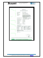
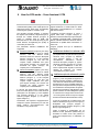
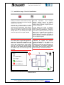
1
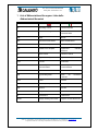
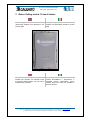
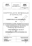
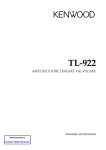
CPA - CELLULAR PHONE AMPLIFIER
http://www.calearotlc.com
User’s guide – Guida utente – V1.2
pag. 1 di 23
CPA-Cellular Phone Amplifier
User’s Guide - Guida utente
Calearo TLC - Via Bacchiglione, 49 - 36033 Isola Vicentina (Vi) - Italy Tel +39 0444-901311 - Fax +39 0444-901375 - www.calearotlc.com
All rights reserved. Calearo TLC can make changes or improvements of the present document in any moment and without notice.
CPA - CELLULAR PHONE AMPLIFIER
http://www.calearotlc.com
User’s guide – Guida utente – V1.2
pag. 2 di 23
Contents - Indice
1
List of Abbreviations/Acronyms- Lista delle Abbreviazioni/Acronimi ... 3
2
Before Getting started - Prima di iniziare ................................................. 4
3
Inside the Package - Dentro la confezione............................................... 5
3.1
4
Optional - Opzione .......................................................................................................................6
Main features – Caratteristiche principali ................................................ 7
4.1
4.2
4.3
5
RF Specifications – Specifiche RF ...............................................................................................7
Mechanical specifications – Caratteristiche meccaniche..............................................................7
Power supply specifications – Specifiche dell’alimentatore.........................................................8
Certification - Certificazione...................................................................... 9
5.1
5.2
Declaration of conformity - Dichiarazione di conformità ............................................................9
Expert opinion – Attestato di conformità....................................................................................10
6
How the CPA works – Come funziona il CPA ......................................... 12
7
Installation - Installazione........................................................................ 14
7.1
Installation steps - Passi di installazione ....................................................................................15
8 Understanding the Amplifier’s LEDs –
Comprendere i LED dell’amplificatore........................................................ 19
9
Array antenna installation – Installazione dell’antenna Array .............. 20
10
Compact antenna installation – Installazione dell’antenna Compact 21
11
Warranty void – Annullamento della garanzia .................................... 22
12
Support – Supporto............................................................................... 23
Calearo TLC - Via Bacchiglione, 49 - 36033 Isola Vicentina (Vi) - Italy Tel +39 0444-901311 - Fax +39 0444-901375 - www.calearotlc.com
All rights reserved. Calearo TLC can make changes or improvements of the present document in any moment and without notice.
CPA - CELLULAR PHONE AMPLIFIER
User’s guide – Guida utente – V1.2
http://www.calearotlc.com
pag. 3 di 23
1 List of Abbreviations/Acronyms- Lista delle
Abbreviazioni/Acronimi
AC
Alternating Current
Corrente Alternata
ALC
Automatic Limiting Control
Controllo Automatico
Potenza d’Uscita
ALM
Alarm
Allarme
BTS
Base Transceiver Station
Stazione Radio Base
CE
Conformité Européenne
Conformité Européenne
CPA
Cellular Phone Amplifier
Amplificatore
Telefonico
DC
Direct Current
Corrente Continua
DCS
Digital Cellular System
Digital Cellular System
FWD
Forward
Trasmettere
GSM
Global System for
Communications
IMD
Intermodulation distortion
Distorsione Intermodulare
LED
Light-emitting diode
Diodo
ad
Luminosa
PWR
Power
Potenza
RF
Radio frequency
Radio Frequenza
RVS
Reverse
Ricevere
RX
Reception
Ricezione
TX
Transmission
Trasmissione
VSWR
Voltage Standing Wave Ratio
Rapporto di Onda Stazionaria
Mobile
Cellulare
Global System for
Communications
Mobile
Emissione
Calearo TLC - Via Bacchiglione, 49 - 36033 Isola Vicentina (Vi) - Italy Tel +39 0444-901311 - Fax +39 0444-901375 - www.calearotlc.com
All rights reserved. Calearo TLC can make changes or improvements of the present document in any moment and without notice.
della
CPA - CELLULAR PHONE AMPLIFIER
http://www.calearotlc.com
User’s guide – Guida utente – V1.2
pag. 4 di 23
2 Before Getting started - Prima di iniziare
The following picture shows a detail of the
(Dual Band) Amplifier Unit described in the
present guide.
La seguente figura mostra un dettaglio del
Amplifier Unit (Dual Band) descritto in questa
guida.
Figure 1 Amplifier Unit
For your safety and to prevent injury to the
installer or the operator, it is essential to read
this manual carefully before your new unit is
installed and in operation.
Per la propria sicurezza e per prevenire
incidenti all’installatore o all’operatore, è
essenziale leggere attentamente questo
manuale prima che l’unità sia installata e
messa in funzione.
Calearo TLC - Via Bacchiglione, 49 - 36033 Isola Vicentina (Vi) - Italy Tel +39 0444-901311 - Fax +39 0444-901375 - www.calearotlc.com
All rights reserved. Calearo TLC can make changes or improvements of the present document in any moment and without notice.
CPA - CELLULAR PHONE AMPLIFIER
User’s guide – Guida utente – V1.2
http://www.calearotlc.com
pag. 5 di 23
3 Inside the Package - Dentro la confezione
Here follows the list of parts inside the
package:
Di seguito la lista degli elementi all’interno
della confezione:
1. Amplifier Unit (Dual Band);
1. (Dual Band) Amplifier Unit;
2. 7.5V DC (Plug-in Power Supply) Adapter;
3. Monopole dual band antenna;
4. Compact Directional antenna with pole
mounting kit, including 5 meters low loss
cable;
5. Array Omnidirectional antenna with pole
mounting kit, including 5 meters low loss
cable;
2. Adattatore
Supply);
DC
7.5V
(Plug-in
Power
3. Antenna monopolo dual band
Omnidirectional;
4. Antenna Compact Directional con kit di
montaggio a palo, inclusi 5 metri di cavo;
5. Antenna Array Omnidirectional con kit di
montaggio a palo, inclusi 5 metri di cavo;
6. Guida utente (questo documento).
6. User’s guide (this document).
2
3
7.5V DC (Plug-in
Power Supply)
Adapter
5
Array
omnidirectional
antenna
antenna
per esterno
1
Monopole dual
band antenna
antenna
per interno
4
Compact Directive
antenna
antenna
per interno
(Dual Band)
Amplifier Unit
amplificatore per interno
Figure 2 Inside the package – Contenuto della confezione.
Calearo TLC - Via Bacchiglione, 49 - 36033 Isola Vicentina (Vi) - Italy Tel +39 0444-901311 - Fax +39 0444-901375 - www.calearotlc.com
All rights reserved. Calearo TLC can make changes or improvements of the present document in any moment and without notice.
CPA - CELLULAR PHONE AMPLIFIER
http://www.calearotlc.com
3.1
User’s guide – Guida utente – V1.2
pag. 6 di 23
Optional - Opzione
Extension cables are available on request.
Sono disponibili cavi prolunga su richiesta.
Remark:
Osservazione:
Additional cable extensions cause signal
attenuation.
I cavi prolunga addizionali
attenuazione del segnale.
causano
per esigenze di cavi più lunghi di 5 mt
si deve usare la versione di CPA E
espansibile art. i0564E
con l' uso di cavi a bassa perdita art. i0072
Calearo TLC - Via Bacchiglione, 49 - 36033 Isola Vicentina (Vi) - Italy Tel +39 0444-901311 - Fax +39 0444-901375 - www.calearotlc.com
All rights reserved. Calearo TLC can make changes or improvements of the present document in any moment and without notice.
CPA - CELLULAR PHONE AMPLIFIER
User’s guide – Guida utente – V1.2
http://www.calearotlc.com
pag. 7 di 23
4 Main features – Caratteristiche principali
4.1
RF Specifications – Specifiche RF
Description
Specifications
Item
FWD
Frequency(MHz)
RVS
GSM
935-960MHz
890-915MHz
DCS
1805-1880MHz
1710-1785MHz
Remarks
Input level
GSM/DCS
-48dBm max
Output level
GSM/DCS
+7dBm max
GSM/DCS
55±2dBm max
(Normal Temperature)
+25℃
GSM/DCS
55±3dBm max
(Operating Temperature)
-10~+40℃
VSWR
Time delay
Tx-Rx Isolation
Shutdown
GSM
DCS
GSM/DCS
GSM/DCS
GSM/DCS
GSM/DCS
7dB max
10dB max
2:1 max
5us max
70dBc min
+10±1dBm
ALC
GSM/DCS
15dB
Gain
Gain Flatness
Spurious
Emission
Noise Figure
GSM/DCS
GSM/DCS
IMD
GSM/DCS
PWR
Alarm
ALM
Impedance
4.2
-36dBm max
7dB max
45dBc min
Normal : green LED on
Normal : red LED on
50Ω
Mechanical specifications – Caratteristiche meccaniche
Dimensions:
Dimensioni:
Amplifier Unit: (L) 220 x (W) 158 x (H) 46
mm
Amplifier Unit: (L) 220 x (W) 158 x (H) 46
mm
Compact Directional Antenna: 170 x
154 x 66 mm
Antenna Compact Directional: 170 x
154 x 66 mm
Omnidirectional Array Antenna: 335 x
40 x 167 mm
Antenna Omnidirectional Array: 335 x
40 x 167 mm
Weight:
Peso:
Amplifier Unit: ~1 kg.
Amplifier Unit: ~1 kg.
Calearo TLC - Via Bacchiglione, 49 - 36033 Isola Vicentina (Vi) - Italy Tel +39 0444-901311 - Fax +39 0444-901375 - www.calearotlc.com
All rights reserved. Calearo TLC can make changes or improvements of the present document in any moment and without notice.
CPA - CELLULAR PHONE AMPLIFIER
http://www.calearotlc.com
pag. 8 di 23
Compact Directional Antenna: ~ 560 gr.
Antenna Compact Directional: ~ 560 gr.
Omnidirectional Array Antenna: ~ 390
gr.
Antenna Omnidirectional Array: ~ 390
gr.
Operating temperature:
0°÷40°C
4.3
User’s guide – Guida utente – V1.2
Temperatura d’esercizio:
0°÷40°C
Power supply specifications – Specifiche dell’alimentatore
ITEM
Input Voltage
Output Voltage
SPECIFICATION
AC 100 ~ 240 V 1.0A , 50~60Hz
DC 7.5 V, 3.0 A
Calearo TLC - Via Bacchiglione, 49 - 36033 Isola Vicentina (Vi) - Italy Tel +39 0444-901311 - Fax +39 0444-901375 - www.calearotlc.com
All rights reserved. Calearo TLC can make changes or improvements of the present document in any moment and without notice.
CPA - CELLULAR PHONE AMPLIFIER
http://www.calearotlc.com
User’s guide – Guida utente – V1.2
pag. 9 di 23
5 Certification - Certificazione
The CPA has been certified according with the
CE directive by the IMQ notified body.
5.1
Il CPA è stato certificato in accordo con la
direttiva CE dall’istituto notificatore IMQ.
Declaration of conformity - Dichiarazione di conformità
Figure 3 Declaration of conformity - Dichiarazione di conformità
Calearo TLC - Via Bacchiglione, 49 - 36033 Isola Vicentina (Vi) - Italy Tel +39 0444-901311 - Fax +39 0444-901375 - www.calearotlc.com
All rights reserved. Calearo TLC can make changes or improvements of the present document in any moment and without notice.
CPA - CELLULAR PHONE AMPLIFIER
http://www.calearotlc.com
5.2
User’s guide – Guida utente – V1.2
pag. 10 di 23
Expert opinion – Attestato di conformità
Figure 4 Expert opinion (page 1) – Attestato di conformità (pagina 1)
Calearo TLC - Via Bacchiglione, 49 - 36033 Isola Vicentina (Vi) - Italy Tel +39 0444-901311 - Fax +39 0444-901375 - www.calearotlc.com
All rights reserved. Calearo TLC can make changes or improvements of the present document in any moment and without notice.
CPA - CELLULAR PHONE AMPLIFIER
http://www.calearotlc.com
User’s guide – Guida utente – V1.2
pag. 11 di 23
Figure 5 Expert opinion (page 2) – Attestato di conformità (pagina 2)
Calearo TLC - Via Bacchiglione, 49 - 36033 Isola Vicentina (Vi) - Italy Tel +39 0444-901311 - Fax +39 0444-901375 - www.calearotlc.com
All rights reserved. Calearo TLC can make changes or improvements of the present document in any moment and without notice.
CPA - CELLULAR PHONE AMPLIFIER
http://www.calearotlc.com
User’s guide – Guida utente – V1.2
pag. 12 di 23
6 How the CPA works – Come funziona il CPA
The CPA is used to improve the
communication quality of the mobile phones in
GSM band and/or DCS band, incomparably
enhancing the signals in a shadow zone.
Il CPA è usato per aumentare la qualità del
segnale telefonico in banda GSM e/o DCS,
migliorando incomparabilmente la ricezione
nelle zone d’ombra.
The repeater (3-Figure 6/Figure 7) receives
the signals from the BTS (1-Figure 6/Figure 7)
through the outside antenna (2-Figure 6/
Figure 7), amplifies them by 55dB, and
transmits them to the mobile phone(s) by the
inside antenna, strengthening the quality of
connectivity in Down-Link.
Il ripetitore (3-Figure 6/Figure 7) riceve i
segnali dalla BTS (1-Figure 6/Figure 7)
attraverso l’antenna esterna (2-Figure 6/Figure
7), amplifica i segnali di 55dB, e li trasmette al
telefono cellulare attraverso l’antenna interna,
irrobustendo la qualità della connessione in
Down-Link.
Two alternative, different installations are
suggested:
Vengono proposti due tipi di installazioni
alternative:
Standard installation (Figure 6), the Array
antenna (2-Figure 6) is used as outside
antenna, and two different inside
antennas should be used: the Monopole
antenna (4-Figure 6), or the Compact
antenna (5-Figure 6). The first one
requires simple installation and gives
good signal coverage; the second one
increases the signal coverage, but
requires pole or wall installation.
Advanced installation (Figure 7), the Array
antenna (2-Figure 7) is used as outside
antenna, and two different inside
antennas should be used: the Monopole
antenna (4-Figure 7), or the Compact
antenna (5-Figure 7). The first one
requires simple installation and gives
good signal coverage; the second one
increases the signal coverage, but
requires pole or wall installation.
In Up-Link, the signal goes in reverse order,
from the mobile phone to the inside antenna
(4/5-Figure 6 or 4/5-Figure 7), to the Amplifier
Unit (3-Figure 6/Figure 7), to the outside
antenna (2-Figure 6/Figure 7), to BTS (1Figure 6/Figure 7).
Furthermore, this repeater is equipped with a
self-protect system (Shut-Down) for both the
bands against Over-Output-Power and
Oscillation, if any should occur.
Installazione standard con antenna a tetto
per amplificazione segnali ottimale (Figure 6),
l’antenna Array (2-Figure 6) utilizzata
come antenna esterna, e due tipi
d’installazione
dell’antenna
interna,
l’antenna Monopole (4-Figure 6), oppure
l’antenna Compact (5-Figure 6). La prima
è di semplice installazione e offre una
buona copertura del segnale; la seconda
migliora la copertura, ma richiede
un’installazione a palo o parete.
Installazione opzionale antenna ext a parete
(Figure 7), si ha una perdita di segnali con 2
antenne Compact (2-Figure 7) utilizzate sia
come antenne esterna ed interna, soluzione
da usarsi solo se non è possibile andare sul
tetto perchè la Compact è direttiva (5-Figure 7)
è una soluzione che farà perdere dei gestori
perchè non tutti saranno nella direzione scelta
questa soluzione si rende obbligatoria quando
le 2 antenne sono troppo vicine tra loro entro
i 5-7 metri (questo causa un loop tra i segnali
uscente ed entrante tale da bloccare il CPA).
In Up-Link, il segnale va in ordine inverso, dal
telefono cellulare (4/5-Figure 6 o 4/5-Figure 7),
all’Amplifier Unit (3-Figure 6/Figure 7),
all’antenna esterna (2-Figure 6/Figure 7), alla
BTS (1-Figure 6/Figure 7).
Inoltre, il ripetitore è equipaggiato con un
sistema di auto protezione (Shut-Down) per
entrambe le bande contro alte potenze in
uscita (Over-Output-Power) e oscillazioni, se
presenti.
Calearo TLC - Via Bacchiglione, 49 - 36033 Isola Vicentina (Vi) - Italy Tel +39 0444-901311 - Fax +39 0444-901375 - www.calearotlc.com
All rights reserved. Calearo TLC can make changes or improvements of the present document in any moment and without notice.
CPA - CELLULAR PHONE AMPLIFIER
http://www.calearotlc.com
User’s guide – Guida utente – V1.2
pag. 13 di 23
Figure 6. CPA con soluzione standard, installazione con antenna esterna sul tetto
Figure 7. CPA con soluzione opzionale, installazione con antenna esterna a parete
Calearo TLC - Via Bacchiglione, 49 - 36033 Isola Vicentina (Vi) - Italy Tel +39 0444-901311 - Fax +39 0444-901375 - www.calearotlc.com
All rights reserved. Calearo TLC can make changes or improvements of the present document in any moment and without notice.
CPA - CELLULAR PHONE AMPLIFIER
http://www.calearotlc.com
User’s guide – Guida utente – V1.2
pag. 14 di 23
7 Installation - Installazione
Warning:
Attenzione:
Calearo TLC refuses responsibility in case
of wrong installation.
Calearo TLC declina ogni responsabilità in
caso di installazione errata.
The installation needs to be made by
qualified technical staff (needing to verify
the installation with a field meter).
L’installazione deve essere fatta da
personale tecnico qualificato (il quale deve
verificare l’installazione con un misuratore
di campo).
The installer shall need to be qualified
according to the Italian law number 46
th
dated 5 march 1990 (46/90) “B”, and need
to be equipped with adequate measuring
devices.
L’installatore deve essere qualificato in
accordo con la legge 46 del 5 marzo 1990
(46/90)
lettera
B,
e
deve
essere
equipaggiato con adeguati strumenti di
misura.
Important:
Importante:
Before connecting the power supply,
ensure that both the inside and outside
antenna cables are connected to the
Amplifier Unit.
Prima
di
connettere
l’alimentazione,
assicurarsi che i connettori dell’antenna
interna ed esterna siano connessi al
Amplifier Unit.
Important:
Importante:
In case of BTS in an area of 200 meters, do
not use the standard configuration.
Alternatively,
use
the
advanced
configuration,
avoiding
pointing
the
Compact antenna in the direction of the
closest BTS.
Non usare la configurazione standard in
presenza di BTS in un raggio di 200 metri.
In alternativa, passare alla configurazione
opzionale, evitando di puntare l’antenna
Compact esterna verso la BTS in vicinanza.
In case of problems, see the section Support.
In caso di problemi, consultare la sezione
Supporto.
Calearo TLC - Via Bacchiglione, 49 - 36033 Isola Vicentina (Vi) - Italy Tel +39 0444-901311 - Fax +39 0444-901375 - www.calearotlc.com
All rights reserved. Calearo TLC can make changes or improvements of the present document in any moment and without notice.
CPA - CELLULAR PHONE AMPLIFIER
http://www.calearotlc.com
7.1
User’s guide – Guida utente – V1.2
pag. 15 di 23
Installation steps - Passi di installazione
Select a location on the outside wall of the
building to install the outside antenna, using a
cell phone in test mode to find the strongest
signal from the cell tower.
The best way to find the location of outside
antenna is simply to walk around your home or
office with your mobile phone, either GSM or
DCS. You should use a mobile phone which
signal you are willing to improve. The “Signal
Strength Meter” on your mobile phone will tell
where the signal is the strongest available.
Selezionare una posizione lungo i muri
perimetrali
dell’edificio
dove
installare
l’antenna esterna, usando un telefono
cellulare in modalità test per identificare la
posizione dove è presente il segnale più forte
proveniente dalla BTS.
Il modo migliore per trovare la posizione
dell’antenna esterna è quello di camminare
lungo il perimetro dell’abitazione o dell’ufficio
con il telefono cellulare, guardando il segnale
GSM o DCS. E’ preferibile usare un telefono
cellulare per il quale si vuole migliorare la
ricezione all’interno. L’indicatore di segnale sul
telefono cellulare può aiutare ad identificare la
zona con migliore segnale.
Note:
Nota:
The mobile phone “Signal Strength Meter”
takes up to 30 seconds to update as you
move from location to location, so make
sure to take a long pause in every location
you test. The place you choose should
either be on the external wall (not below
the window level) or on the roof top of the
building.
L’indicatore di segnale sul telefono
cellulare impiega fino a 30 secondi per
aggiornarsi mentre il telefono è in
movimento, quindi fare una lunga pausa in
ogni posizione. La posizione selezionata
deve essere vicina al muro esterno (non
sotto le finestre) o sul tetto dell’edificio.
Figure 8 Selecting the position for the outside antenna - Selezionare la posizione per
l'antenna esterna.
Calearo TLC - Via Bacchiglione, 49 - 36033 Isola Vicentina (Vi) - Italy Tel +39 0444-901311 - Fax +39 0444-901375 - www.calearotlc.com
All rights reserved. Calearo TLC can make changes or improvements of the present document in any moment and without notice.
CPA - CELLULAR PHONE AMPLIFIER
http://www.calearotlc.com
User’s guide – Guida utente – V1.2
pag. 16 di 23
Note:
Nota:
Do not install the outside antenna in the
bad installation areas.
Non installare l’antenna esterna in un’area
con assenza di segnale.
Select a temporary position 1 for the inside
antenna.
Selezionare una posizione 2 temporanea per
l’antenna.
Referring to the standard installation, inside
the package there are two different inside
antennas. The first one (Example A) can be
installed directly to the Amplification Unit, but
the coverage area is not so big. The second
one (Example B) can give a wide coverage
area.
In riferimento all’installazione standard,
all’interno della scatola sono presenti due
antenne interne. La prima (Esempio A) può
essere installata direttamente sull’Amplifier
Unit, ma la copertura fornita potrebbe essere
ridotta. La seconda (Esempio B) garantisce
copertura per un’area maggiore.
Note:
Nota:
It is suggested to try with the first antenna
first, and then the second one in case the
coverage of the inside area is not
satisfactory.
Si suggerisce di provare inizialmente con
la prima antenna, e di passare alla seconda
nel caso in cui la copertura dell’area
interna non sia sufficiente.
Example A – Esempio A
Example B – Esempio B
Figure 9 Inside antenna installation - Installazione antenna interna
Warning:
Attenzione:
Please do not install metal objects in front
Non installare oggetti metallici di fronte
of the antennas.
alle antenne.
1
The pictures in this page are purely indicative. The attenuation of the space coverage due to the walls or other objects
is related to the typology and thickness of the materials, and to the antenna distance.
2
Le figure in questa pagina sono puramente illustrative. La perdita di copertura causata dai muri o da altri oggetti è
funzione della tipologia e dello spessore dei materiali, e della distanza dall’antenna.
Calearo TLC - Via Bacchiglione, 49 - 36033 Isola Vicentina (Vi) - Italy Tel +39 0444-901311 - Fax +39 0444-901375 - www.calearotlc.com
All rights reserved. Calearo TLC can make changes or improvements of the present document in any moment and without notice.
CPA - CELLULAR PHONE AMPLIFIER
http://www.calearotlc.com
User’s guide – Guida utente – V1.2
pag. 17 di 23
Note:
Nota Importante:
The outside antenna should be kept, at
least, 1 meter away from mobile phones
and 7 meters from the inside antenna.
L’antenna esterna deve essere installata ad
almeno 1 metro di distanza dai telefoni
cellulari e 7 metri minimo dall’antenna interna.
Important:
Nota Importante:
Make sure that outside antenna does not
face the inside antenna, has this may
cause Oscillation and Shut-Down.
Assicurarsi che l’antenna esterna non sia
orientata in direzione dell’antenna interna,
altrimenti possono verificarsi oscillazioni e
Shut Down( o blocco del sistema).
Connect the outside and inside antennas to
the Amplifier Unit using the right connectors.
Collegare l’antenna interna ed esterna al
Amplifier Unit usando il corretto connettore.
Note:
Nota:
When plugging the connectors, pay
attention not to damage the center pins.
Durante la connessione, fare attenzione a
non danneggiare il pin centrale del
connettore.
Note:
Nota:
Select a location to install the Amplifier
Unit with proper ventilation, away from
excessive heat, direct sunlight, or humidity.
Installare l’Amplifier Unit in un luogo
ventilato, lontano da fonti di calore, dalla
luce diretta del sole e dall’umidità.
Place the Amplifier Unit where you want the
signal to be rebroadcasted. Make sure that the
outside antenna and the Amplifier Unit are as
far away from each other as possible, and
separated by at least a wall if possible.
Fissare l’Amplifier Unit dove si vuole che il
segnale venga amplificato. Cercare di fare in
modo che l’Amplifier Unit e l’antenna esterna
siano il più lontano possibile l’una dall’altra e
separate almeno da un muro e distanti almeno
7 metri ed usare la soluzione di figura 7.
Plug the supplied power supply into the
Amplifier Unit (do not connect the DC adapter
to a wall outlet).
Collegare il cavo dell’alimentatore all’Amplifier
Unit (non connettere l’adattatore DC alla presa
a muro).
Verify again that the inside antenna is at least
at 7 meters from the outside antenna.
Check whether the antenna coaxial cables are
Verificare ancora che l’antenna interna sia ad
una distanza di almeno 7 metri dall’antenna
esterna.
Calearo TLC - Via Bacchiglione, 49 - 36033 Isola Vicentina (Vi) - Italy Tel +39 0444-901311 - Fax +39 0444-901375 - www.calearotlc.com
All rights reserved. Calearo TLC can make changes or improvements of the present document in any moment and without notice.
CPA - CELLULAR PHONE AMPLIFIER
http://www.calearotlc.com
User’s guide – Guida utente – V1.2
properly connected to the Amplifier Unit.
Then, plug the DC adapter into an electrical
socket.
pag. 18 di 23
Controllare che i cavi di antenna siano
opportunamente connessi all’Amplifier Unit.
Collegare l’adattatore DC alla presa elettrica.
The unit’s power “on” light should turn green,
signalling that the Amplifier Unit is operating.
Il led power “on” dell’unità diventa verde,
segnalando che l’Amplifier Unit è accesa.
Note:
Nota:
The Amplifier Unit should be kept, at least,
1 meter away from any mobile phone.
L’Amplifier Unit deve comunque stare a
circa 1 metro dal telefono cellulare.
Note:
Nota:
Make sure never orientate the outside
antenna in the direction of the Amplifier
Unit or of the inside antenna.
Assicurarsi che l’antenna esterna non sia
mai orientata direttamente verso l’Amplifier
Unit o l’antenna interna.
Verify with a mobile phone the correct
installation of the repeater inside the building.
Verificare con un telefono cellulare la corretta
installazione dell’Amplifier Unit all’interno
dell’edificio.
If the installation is correct, fix the inside
antenna and the Amplifier Unit on the wall.
Se l’installazione è corretta, fissare l’antenna
interna e l’Amplifier Unit al muro.
Calearo TLC - Via Bacchiglione, 49 - 36033 Isola Vicentina (Vi) - Italy Tel +39 0444-901311 - Fax +39 0444-901375 - www.calearotlc.com
All rights reserved. Calearo TLC can make changes or improvements of the present document in any moment and without notice.
CPA - CELLULAR PHONE AMPLIFIER
http://www.calearotlc.com
User’s guide – Guida utente – V1.2
pag. 19 di 23
8 Understanding the Amplifier’s LEDs – Comprendere i LED
dell’amplificatore
Figure 10 Amplifier LEDs - LED dell'amplificatore
During the normal operation of GSM and
DCS bands only the green “PWR” light is
on.
In case of Shut-Down of GSM (or DCS)
band, when Output Power Overload or
Oscillation occur for longer than 5
seconds:
1. The red light of GSM (or DCS) turns
on, indicating the Shut-Down mode.
The Shut-Down will last for 5
seconds. Then it will automatically
return to Normal Operation (first autoreset).
2. If Output Power Overload or
Oscillation continues even after the
first auto-reset, the red light (ShutDown) will turn on again. The autoreset will take place up to 3 times.
3. When
Over-Output-Power
or
Oscillation still exists after the third
auto-reset, the Shut-Down will be for
60 seconds before the next auto-reset
occur.
4. The Shut-Down function will repeat
steps 1 through 3 continuously and
automatically, until the corrective
action steps as follows are taken:
A.
Place the Amplifier Unit or the
inside antenna sufficiently away
from the outside antenna.
Lo spegnimento si attiva in caso di Output
Power Overload o oscillazione nella
banda GSM (o DCS), per un periodo
maggiore a 5 secondi:
BLOCCO DEL SISTEMA
1. La luce rossa del GSM (or DCS) si
accende, indicando la modalità di
spegnimento. Lo spegnimento dura 5
secondi. In seguito, il dispositivo
ritorna al funzionamento normale
(primo auto-reset).
2. Se l’Output Power Overload o
l’oscillazione persiste dopo il primo
auto-reset,
la
luce
rossa
(spegnimento)
si
accende
nuovamente. L’ Auto-reset si ripete per
tre volte.
3. Quando l’Output Power Overload o
l’oscillazione persiste dopo il terzo
auto-reset, il dispositivo si spegne per
60 secondi prima di effettuare il
successivo auto-reset.
4. La funzione di spegnimento ripeterà i
passi da 1 a 3 in continuazione fino a
che non verranno realizzate le
seguenti azioni correttive:
SOLUZIONI
Or:
B.
Durante il normale funzionamento delle
bande GSM e DCS solamente la
segnalazione PWR è accesa, colore
verde.
Make sure that the outside
antenna is facing away from the
Amplifier Unit and the inside
antenna.
A. Piazzare l'amplificatore o l' antenna
interna lontana da quella esterna.
Assicurarsi che l’antenna esterna
non sia diretta verso l’Amplificatore
o l’antenna interna.
B. oppure sostituire l’antenna esterna
con una Compact orientandola
di schiena alla Compact interna.
Calearo TLC - Via Bacchiglione, 49 - 36033 Isola Vicentina (Vi) - Italy Tel +39 0444-901311 - Fax +39 0444-901375 - www.calearotlc.com
All rights reserved. Calearo TLC can make changes or improvements of the present document in any moment and without notice.
CPA - CELLULAR PHONE AMPLIFIER
http://www.calearotlc.com
User’s guide – Guida utente – V1.2
pag. 20 di 23
9 Array antenna installation – Installazione dell’antenna Array
In order to have the best performances from
the device, you should observe the following
guidelines when you install the Array antenna.
Per avere le migliori prestazioni dal dispositivo
occorre osservare le seguenti linee guida per
l’installazione dell’antenna Array.
Figure 11 Array antenna installation - Installazione dell'antenna array.
Important notes:
Note importanti:
Always install the antenna in vertical
position as shown by the mark "ALTO"
(“UP”) printed on it.
Installare sempre l’antenna in posizione
verticale, come mostrato dalla scritta
sovraimpressa "ALTO".
The height from the ground must be at
least 1,5 m, in order to reduce reflections.
L’altezza dal pavimento deve essere di
almeno 1,5 m, per ridurre l’effetto delle
riflessioni.
Install the antenna as far away as
possible from metal parts or structures.
Pole installation (A):
The installation on a pole (optional)
enhances
the
omnidirectional
performances of the antenna; the fixing
can be made by the bracket pole kit
included in the package, the pole
diameter can vary from Ø30 mm to Ø42
mm.
Wall installation (B - C):
The wall installation needs screw anchors
(not included in the package) with not
countersunk screws. In case of use of the
countersunk screws, add washers to
protect the antenna.
The cable can be inserted into a hole in
the wall (B) or bended into the 90° bracket
slot (C), in order to protect it from buckling
or breaking.
Installare l’antenna quanto più lontano
possibile da parti e strutture metalliche.
Installazione a palo (A):
L’installazione a palo (opzionale) migliora
le
prestazioni
omnidirezionali
dell’antenna. Il fissaggio può essere fatto
su una staffa a palo di diametro variabile
da Ø30 mm a Ø42 mm.
Installazione a parete (B - C):
L’installazione a muro richiede viti di
fissaggio con tasselli ad espansione (non
forniti nella confezione), possibilmente
con viti a testa cilindrica non svasate. Nel
caso
si
utilizzino
viti
svasate
salvaguardare con delle rondelle l’integrità
dell’antenna.
Il cavo può essere infilato attraverso un
eventuale foro sul muro (B) o ripiegato
nell’asola della staffa a 90° dell’antenna
(C), in modo tale da preservarlo da
schiacciamento o rottura.
Calearo TLC - Via Bacchiglione, 49 - 36033 Isola Vicentina (Vi) - Italy Tel +39 0444-901311 - Fax +39 0444-901375 - www.calearotlc.com
All rights reserved. Calearo TLC can make changes or improvements of the present document in any moment and without notice.
CPA - CELLULAR PHONE AMPLIFIER
http://www.calearotlc.com
User’s guide – Guida utente – V1.2
pag. 21 di 23
10 Compact antenna installation – Installazione dell’antenna
Compact
In order to obtain the best performances from
the device, the following guidelines when
installing the antenna should be observed.
Per avere le migliori prestazioni dal dispositivo
occorre osservare le seguenti linee guida per
l’installazione dell’antenna.
Figure 12 Compact antenna installation - Installazione dell'antenna Compact
Important notes:
Always install the antenna in vertical
position as shown in figure.
The height from the ground must be at
least 180~200 cm.
Install the antenna as far away as
possible from metal parts or structures (at
least 1 meter).
Do not put objects in front of the antenna.
Pole installation:
The fixing can be made by the bracket
pole kit included in the package; the pole
diameter can vary from Ø30 mm to Ø42
mm.
Wall installation:
The wall installation needs screw anchors
(not included in the package) with not
countersunk screws. In case of use of the
countersunk screws, add washers to
protect the antenna.
Note importanti:
Installare sempre l’antenna nel verso della
polarizzazione verticale, come indicato
nella figura.
Fissare l’antenna a circa 180÷200 cm da
terra.
Posizionare l’antenna ad almeno 1 m da
strutture o parti metalliche.
Evitare di posizionare oggetti davanti
all’antenna.
Installazione a palo:
Il fissaggio può essere fatto mediante il kit
di staffaggio a palo incluso nella
confezione; il diametro del palo può
variare da Ø30 a Ø42 mm.
Installazione a parete:
L’installazione a parete va eseguita
mediante fissaggio con tasselli ad
espansione (non forniti nella confezione),
possibilmente con viti a testa cilindrica
non svasate. Nel caso si utilizzino viti
svasate salvaguardare con delle rondelle
l’integrità dell’antenna.
Calearo TLC - Via Bacchiglione, 49 - 36033 Isola Vicentina (Vi) - Italy Tel +39 0444-901311 - Fax +39 0444-901375 - www.calearotlc.com
All rights reserved. Calearo TLC can make changes or improvements of the present document in any moment and without notice.
CPA - CELLULAR PHONE AMPLIFIER
http://www.calearotlc.com
User’s guide – Guida utente – V1.2
pag. 22 di 23
11 Warranty void – Annullamento della garanzia
The warranty of the product will be void in
case warranty labels (see details in the next
picture) will be removed or broken (torn) from
the Amplifier Unit.
La garanzia del prodotto sarà nulla nel caso
una delle etichette della garanzia (vedere il
dettaglio nella figura successiva) siano
rimosse o strappate dall’Amplifier Unit.
Figure 13 Warranty label detail - Dettaglio etichetta garanzia
Calearo TLC - Via Bacchiglione, 49 - 36033 Isola Vicentina (Vi) - Italy Tel +39 0444-901311 - Fax +39 0444-901375 - www.calearotlc.com
All rights reserved. Calearo TLC can make changes or improvements of the present document in any moment and without notice.
CPA - CELLULAR PHONE AMPLIFIER
http://www.calearotlc.com
User’s guide – Guida utente – V1.2
pag. 23 di 23
12 Support – Supporto
Should you have any question, comments, or
problems with the installation or with the use of
the Cellular Phone Amplifier Kit, please
contact your installer.
ASSISTENZA TECNICA
Per domande preliminari sul vs. progetto tecnico
per realizzare l' impianto di amplificazione CPA
o in caso di domande, commenti, o problemi
con l’installazione o con l’uso del presente kit
Cellular Phone Amplifier,
contattare in primis il proprio
rivenditore o il ns. centro di assistenza:
--- al telefono 335 7127437
--- o inviando un fax 02 700436212
--- o un email: [email protected]
NORMATIVA PER L' INSTALLAZIONE
DI ESTENSORI GSM-UMTS
LA DIREZIONE GENERALE PER I SERVIZI DI COMUNICAZIONE ELETTRONICA E
RADIODIFFUSIONE, IN MERITO ALLA CORRETTA INSTALLAZIONE DI APPARATI
AMPLIFICATORI E/O RIPETITORI DI SEGNALI TELEFONICI GSM-UMTS, CON CIRCOLARE
DEL 14 FEBBRAIO 2008, HA CHIARITO CHE LE APPARACCHIATURE IN ESAME DEVONO
ESSERE INSTALLATE ESCLUSIVAMENTE DA PARTE DI OPERATORI DI TELEFONIA MOBILE
TITOLARI DELLE RELATIVE LICENZE, O DITTE INSTALLATRICI DA ESSI AUTORIZZATI
Calearo TLC - Via Bacchiglione, 49 - 36033 Isola Vicentina (Vi) - Italy Tel +39 0444-901311 - Fax +39 0444-901375 - www.calearotlc.com
All rights reserved. Calearo TLC can make changes or improvements of the present document in any moment and without notice.