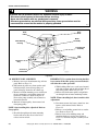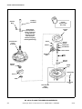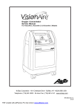
1
Service Automatic Washers Refer to Page 5 for Model Numbers W194P www.comlaundry.com Part No. 24163R6 March 2005 Table of Contents Section 1 – Safety Information Locating an Authorized Servicer ............................4 Section 2 – Introduction Model Identification ................................................5 Customer Service ....................................................5 Nameplate Location ................................................5 Section 3 – Troubleshooting 1. 2. 3. 4. 5. 6. 7. 8. 9. 10. No Hot Water ...................................................7 No Cold Water .................................................7 No Warm Water ...............................................8 Water Fill Does Not Stop At Proper Level ......8 Timer Does Not Advance ................................8 No Agitation .....................................................9 Constant Agitation ...........................................9 Slow Spin or No Spin ....................................10 Constant Spin .................................................10 Drive Motor Overload Protector Cycles Repeatedly ......................................................10 11. Outer Tub Does Not Empty ...........................11 12. Excessive Vibration .......................................11 13. Water Leaking From Outer Tub .....................11 14. Power Cord To Control Hood ........................13 15. Control Hood To Bottom Flange Of Control Panel ...............................................................13 16. Main Wire Harness To Top Rear Flange Of Cabinet ...........................................................14 17. Motor To Motor Mounting Bracket, To Base 14 Section 5 – Service Procedures 24163 Section 6 – Adjustments 46. 47. 48. 49. 50. 51. Timer Knob Indicator ....................................47 Leveling Legs .................................................47 Pressure Switch ..............................................48 Belt – Agitate And Spin .................................48 Belt (Pump) ....................................................48 Out-Of-Balance Switch Trigger .....................49 Section 7 – Test Procedures Section 4 – Grounding 18. 19. 20. 21. 22. 23. 24. 25. 26. 27. 28. 29. 30. 31. 32. 33. Pump Assembly .............................................26 34. Cabinet Top Assembly ...................................27 35. Door and Out-of-Balance Switch and Bracket Assembly ........................................................28 36. Mixing Valve Assembly ................................29 37. Washtub and Lint Filter .................................29 38. Water Seal Assembly .....................................31 39. Outer Tub .......................................................34 40. Drive Pulley And Helix .................................36 41. Brake Assembly .............................................37 42. Lower Bearing Housing .................................38 43. Transmission Assembly .................................40 44. Balance Ring ..................................................45 45. Upper Bearing Assembly ...............................46 Control Panel ..................................................15 Timer ..............................................................16 Temperature or Speed (Action) Switch .........17 Pressure Switch ..............................................17 Drain Hose Elbow ..........................................18 Loading Door .................................................18 Agitator Post Assembly .................................18 Agitator Drive Shaft .......................................20 Front Panel .....................................................20 Pump Belt .......................................................20 Drive Belt .......................................................21 Motor And Mounting Bracket ........................23 Idler Lever and Pulley ....................................26 Motor Drive Pulley or Pump Pulley ..............26 Motor Switch ..................................................26 Section 8 – Cycle Sequence Charts Timer No. 27694 Cycle Sequence (Two Cycle–Mallory) ...........................................53 Timer No. 28918 Cycle Sequence (Two Cycle) ..........................................................54 Timer No. 28093 Cycle Sequence (Three Cycle – Mallory) .......................................55 Timer No. 28917 Cycle Sequence (Three Cycle) ........................................................56 Timer No. 29966 Cycle Sequence (Three Cycle) ........................................................57 Timer No. 27693 Cycle Sequence (Four Cycle – Mallory) .........................................58 Timer No. 28919 Cycle Sequence (Four Cycle) ..........................................................59 Section 9 – Internal Wiring of Washer Motor Switch .....................................................................61 © Copyright, Alliance Laundry Systems LLC – DO NOT COPY or TRANSMIT 1 Notes 2 © Copyright, Alliance Laundry Systems LLC – DO NOT COPY or TRANSMIT 24163 Section 1 Safety Information Throughout this manual and on machine decals, you will find precautionary statements (“CAUTION,” “WARNING,” and “DANGER”) followed by specific instructions. These precautions are intended for the personal safety of the operator, user, servicer and those maintaining the machine. a DANGER Danger indicates an imminently hazardous situation that, if not avoided, will cause severe personal injury or death. a WARNING Warning indicates a hazardous situation that, if not avoided, could cause severe personal injury or death. a CAUTION Caution indicates a hazardous situation that, if not avoided, may cause minor or moderate personal injury or property damage. Additional precautionary statements (“IMPORTANT” and “NOTE”) are followed by specific instructions. IMPORTANT The word “IMPORTANT” is used to inform the reader of specific procedures where minor machine damage will occur if the procedure is not followed. NOTE The word “NOTE” is used to communicate installation, operation, maintenance or servicing information that is important but not hazard related. In the interest of safety, some general precautions relating to the operation of this machine follow. WARNING • Failure to install, maintain and/or operate this product according to the manufacturer’s instructions may result in conditions which can produce serious injury, death and/or property damage. • Do not repair or replace any part of the product or attempt any servicing unless specifically recommended or published in this Service Manual and unless you understand and have the skills to carry out the servicing. • Whenever ground wires are removed during servicing, these ground wires must be reconnected to ensure that the product is properly grounded and to reduce the risk of fire, electric shock, serious injury or death. W006R2 24163 © Copyright, Alliance Laundry Systems LLC – DO NOT COPY or TRANSMIT 3 Section 1 WARNING To reduce the risk of electric shock, fire, explosion, serious injury or death: • Disconnect electric power to the washer before servicing. • Never start the washer with any guards/panels removed. • Whenever ground wires are removed during servicing, these ground wires must be reconnected to ensure that the washer is properly grounded. W003 WARNING Repairs that are made to your products by unqualified persons can result in hazards due to improper assembly or adjustments subjecting you or the inexperienced person making such repairs to the risk of serious injury, electrical shock or death. W007 WARNING If you or an unqualified person perform service on your product, you must assume the responsibility for any personal injury or property damage which may result. The manufacturer will not be responsible for any injury or property damage arising from improper service and/or service procedures. W008 NOTE: The WARNINGS and IMPORTANT INSTRUCTIONS appearing in this manual are not meant to cover all possible conditions and situations that may occur. Common sense, caution and care must be exercised when installing, maintaining or operating the washer. Always contact your dealer, distributor, service agent or the manufacturer about any problems or conditions you do not understand. Locating an Authorized Servicer Alliance Laundry Systems is not responsible for personal injury or property damage resulting from improper service. Review all service information before beginning repairs. Warranty service must be performed by an authorized technician, using authorized factory parts. If service is required after the warranty expires, Alliance Laundry Systems also recommends contacting an authorized technician and using authorized factory parts. 4 © Copyright, Alliance Laundry Systems LLC – DO NOT COPY or TRANSMIT 24163 Section 2 Introduction Model Identification Information in this manual is applicable to these washer models: HA1000 HA1000-3059 HA2010 HA2300 HA2410 HA2411 HA2620 HA2621 HA3000 HA3001 HA4000 HA4001 HA4010 HA4010-1088 HA4010-2200 HA4010-3059 HA4011 HA4011-1088 HA4011-2200 HA4011-3059 HA4020 HA4021 HA4210 HA4210-2200 HA4211 HA4211-2200 HA4260 HA4261 HA4290 HA4291 HA4340 HA4341 HA4370 HA4371 HA4500 HA4501 HA4510 HA4511 HA4511-3050 HA4511-3062 HA4520 HA4521 HA4590 HA4591 HA5000 HA5001 HA5320 HA5321 HA5590 HA5591 HA6000 HA6001 HA6420 HA6421 HA6450 HA6452 HA6470 HA6471 HA7000 HA7001 HA7221 Customer Service If literature or replacement parts are required, contact the source from whom the machine was purchased or contact Alliance Laundry Systems at (920) 748-3950 for the name and address of the nearest authorized parts distributor. For technical assistance, call (920) 748-3121. Nameplate Location When calling or writing about your product, be sure to mention model and serial numbers. Model and serial numbers are located on nameplate(s) as shown. 24163 © Copyright, Alliance Laundry Systems LLC – DO NOT COPY or TRANSMIT Nameplate 5 Section 2 Introduction Notes 6 © Copyright, Alliance Laundry Systems LLC – DO NOT COPY or TRANSMIT 24163 Section 3 Troubleshooting WARNING To reduce the risk of electric shock, fire, explosion, serious injury or death: • Disconnect electric power to the washer before servicing. • Never start the washer with any guards/panels removed. • Whenever ground wires are removed during servicing, these ground wires must be reconnected to ensure that the washer is properly grounded. W003 IMPORTANT: Refer to appropriate wiring diagram for aid in testing washer components. 1. NO HOT WATER POSSIBLE CAUSE TO CORRECT Hot water supply valve is closed. Water supply is cold. Kinked hot water inlet hose. Clogged mixing valve screen, or screen in outer end of inlet hose nearest water supply valve. Inoperative hot water mixing valve solenoid. Inoperative timer. Inoperative temperature switch. Inoperative pressure switch. Clogged pressure hose. Broken, loose or incorrect wiring. Open valve. Check water heater. Straighten or replace hose. Disconnect hot water inlet hose, and clean or replace screen. Test solenoid and replace if inoperative. Test timer and replace if inoperative. Test switch and replace if inoperative. Test switch and replace if inoperative. Remove and clean hose. Refer to appropriate wiring diagram. 2. NO COLD WATER POSSIBLE CAUSE TO CORRECT Cold water supply valve is closed. Kinked cold water inlet hose. Clogged mixing valve screen, or screen in outer end of inlet hose nearest water supply valve. Inoperative cold water mixing valve solenoid. Inoperative timer. Inoperative temperature switch. Inoperative pressure switch. Clogged pressure hose. Broken, loose or incorrect wiring. Open valve. Straighten or replace hose. Disconnect cold water inlet hose, and clean or replace screen. Test solenoid and replace if inoperative. Test timer and replace if inoperative. Test switch and replace if inoperative. Test switch and replace if inoperative. Remove and clean hose. Refer to appropriate wiring diagram. 24163 © Copyright, Alliance Laundry Systems LLC – DO NOT COPY or TRANSMIT 7 Section 3 Troubleshooting WARNING To reduce the risk of electric shock, fire, explosion, serious injury or death: • Disconnect electric power to the washer before servicing. • Never start the washer with any guards/panels removed. • Whenever ground wires are removed during servicing, these ground wires must be reconnected to ensure that the washer is properly grounded. W003 3. NO WARM WATER POSSIBLE CAUSE TO CORRECT No hot water. No cold water. Refer to Paragraph 1. Refer to Paragraph 2. 4. WATER FILL DOES NOT STOP AT PROPER LEVEL POSSIBLE CAUSE TO CORRECT Inoperative pressure switch. Air leak in pressure hose. Sediment on or under mixing valve diaphragm, defective diaphragm, or armature binding in armature guide. Broken, weak or missing mixing valve armature spring. Test switch and replace if inoperative. Replace hose. Disassemble and clean mixing valve. Replace deteriorated or not easily cleaned components. Refer to parts manual for assembly sequence of valve. Disassemble valve and replace spring. Refer to parts manual for assembly sequence of valve. A siphoning action started in washer will cause water to Install No. 562P3 Siphon Break Kit. be siphoned from the washer during the cycle due to the end of the drain hose being lower than cabinet top of washer. Water in pressure hose. Blow air through hose to remove water. Broken, loose, shorted or incorrect wiring. Refer to appropriate wiring diagram. 5. TIMER DOES NOT ADVANCE POSSIBLE CAUSE TO CORRECT Timer is designed to pause during fill periods. Inoperative timer. Timer in "OFF" position of SOAK CYCLE. Loading door is open. Washer will not fill. Timer motor lead wire off timer terminal. Broken, loose or incorrect wiring. Allow completion of fill period. Test timer, and replace if inoperative. Manually advance timer to SPIN. Close loading door. Timer pauses until pressure switch is satisfied. Refer to appropriate wiring diagram and reattach wire. Refer to appropriate wiring diagram. 8 © Copyright, Alliance Laundry Systems LLC – DO NOT COPY or TRANSMIT 24163 Section 3 Troubleshooting WARNING To reduce the risk of electric shock, fire, explosion, serious injury or death: • Disconnect electric power to the washer before servicing. • Never start the washer with any guards/panels removed. • Whenever ground wires are removed during servicing, these ground wires must be reconnected to ensure that the washer is properly grounded. W003 6. NO AGITATION POSSIBLE CAUSE TO CORRECT *Inoperative timer. Inoperative action switch. Inoperative motor. Inoperative pressure switch. Broken, loose or incorrect wiring. Loose or broken drive belt. Inoperative transmission assembly. Sheared motor pulley roll pin. Test timer and replace if inoperative. Test switch and replace if inoperative. Test motor and replace if inoperative. Test switch and replace if inoperative. Refer to appropriate wiring diagram. Adjust or replace belt. Replace transmission assembly. Remove drive motor, and replace roll pin and any other damaged parts. Refer to Paragraph 10. Replace pump. Close door and test switch and replace if inoperative. Drive motor overload protector has cycled. Bind in pump. Loading door is open or door switch is inoperative. *Timer is designed to pause (SOAK) during the HANDWASH/KNIT or DELICATE cycle. 7. CONSTANT AGITATION POSSIBLE CAUSE TO CORRECT Inoperative timer. Inoperative drive motor. Shorted or incorrect wiring. Test timer and replace if inoperative. Test motor and replace if inoperative. Refer to appropriate wiring diagram. 24163 © Copyright, Alliance Laundry Systems LLC – DO NOT COPY or TRANSMIT 9 Section 3 Troubleshooting WARNING To reduce the risk of electric shock, fire, explosion, serious injury or death: • Disconnect electric power to the washer before servicing. • Never start the washer with any guards/panels removed. • Whenever ground wires are removed during servicing, these ground wires must be reconnected to ensure that the washer is properly grounded. W003 8. SLOW SPIN OR NO SPIN POSSIBLE CAUSE TO CORRECT Inoperative timer. Inoperative action switch. Some model washers, the timer is programmed for SLOW spin in the DELICATE CYCLE regardless of the action switch setting. Loading door is open or door safety switch is inoperative. Bind in water pump. Inoperative drive motor. Loose or broken drive belt. Washer has gone OUT-OF-BALANCE. No clearance or stuck brake pads. Broken, loose or incorrect wiring. Test timer and replace if inoperative. Test switch and replace if inoperative. Use a different cycle. Close loading door, or test switch and replace if inoperative. Replace pump. Test motor and replace if inoperative. Adjust or replace spin belt. Open loading door to reset out-of-balance switch. Free sticky brake pads or replace pads. Refer to appropriate wiring diagram. 9. CONSTANT SPIN POSSIBLE CAUSE TO CORRECT Inoperative timer. Inoperative drive motor. Excessive wear on brake pads, or missing brake pads. Shorted or incorrect wiring. Test timer and replace if inoperative. Test motor and replace if inoperative. Replace brake pads. Refer to appropriate wiring diagram. 10. DRIVE MOTOR OVERLOAD PROTECTOR CYCLES REPEATEDLY POSSIBLE CAUSE TO CORRECT Excessive belt tension. Inoperative motor overload protector. Bind in water pump. Bind in transmission. Brake pads binding. Adjust belts. Replace motor. Replace pump. Replace transmission. Free binding pads, or replace pads. 10 © Copyright, Alliance Laundry Systems LLC – DO NOT COPY or TRANSMIT 24163 Section 3 Troubleshooting WARNING To reduce the risk of electric shock, fire, explosion, serious injury or death: • Disconnect electric power to the washer before servicing. • Never start the washer with any guards/panels removed. • Whenever ground wires are removed during servicing, these ground wires must be reconnected to ensure that the washer is properly grounded. W003 11. OUTER TUB DOES NOT EMPTY POSSIBLE CAUSE TO CORRECT Kinked drain hose. Inoperative water pump. Obstruction in outer tub outlet hose. Loose pump belt. Straighten hose. Replace pump. Remove obstruction. Adjust belt. 12. EXCESSIVE VIBRATION POSSIBLE CAUSE TO CORRECT Unbalanced load in tub. Broken, disconnected or centering spring(s) out of adjustment. Washer is not properly leveled. Washer is installed on weak, "spongy" or built-up floor. Stop washer, redistribute load, then restart washer. Connect or replace centering spring(s). Spring should be located in center notch. Refer to Figure 32. Adjust leveling legs. Relocate washer, or support floor to eliminate weak or "spongy" condition. Replace with correct screws or tighten. Incorrect or loose cabinet screws. 13. WATER LEAKING FROM OUTER TUB POSSIBLE CAUSE TO CORRECT Leaking water seal in outer tub. Hole in outer tub. Pressure hose bulb leaking. Outer tub cover gasket leaking. Replace water seal assembly. Refer to Paragraph 38. Replace outer tub. Replace pressure hose and/or bulb. Replace gasket. 24163 © Copyright, Alliance Laundry Systems LLC – DO NOT COPY or TRANSMIT 11 Section 3 Troubleshooting Notes 12 © Copyright, Alliance Laundry Systems LLC – DO NOT COPY or TRANSMIT 24163 Section 4 Grounding WARNING To reduce the risk of electric shock, fire, explosion, serious injury or death: • Disconnect electric power to the washer before servicing. • Never start the washer with any guards/panels removed. • Whenever ground wires are removed during servicing, these ground wires must be reconnected to ensure that the washer is properly grounded. W003 14. POWER CORD TO CONTROL HOOD Ground Wire Figure 1 15. CONTROL HOOD TO BOTTOM FLANGE OF CONTROL PANEL Ground Wire Figure 2 24163 © Copyright, Alliance Laundry Systems LLC – DO NOT COPY or TRANSMIT 13 Section 4 Grounding WARNING To reduce the risk of electric shock, fire, explosion, serious injury or death: • Disconnect electric power to the washer before servicing. • Never start the washer with any guards/panels removed. • Whenever ground wires are removed during servicing, these ground wires must be reconnected to ensure that the washer is properly grounded. W003 16. MAIN WIRE HARNESS TO TOP REAR FLANGE OF CABINET Ground Wire on Cabinet Flange (Some models) Ground Wire on Cabinet Corner Gusset (Some models) Figure 3 17. MOTOR TO MOTOR MOUNTING BRACKET, TO BASE Ground Wire Figure 4 14 © Copyright, Alliance Laundry Systems LLC – DO NOT COPY or TRANSMIT 24163 Section 5 Service Procedures WARNING To reduce the risk of electric shock, fire, explosion, serious injury or death: • Disconnect electric power to the washer before servicing. • Never start the washer with any guards/panels removed. • Whenever ground wires are removed during servicing, these ground wires must be reconnected to ensure that the washer is properly grounded. W003 18. CONTROL PANEL Refer to Figure 5 or 6. a. Remove panel assembly screws and lift assembly off panel support. b. Remove end caps. c. Remove timer knob assembly. WARNING DISCONNECT POWER CORD AND CLOSE WATER SUPPLY VALVE BEFORE SERVICING WASHER. NEVER ENERGIZE THE ELECTRICAL POWER TO THE WASHER WITH ANY OF THE PANELS REMOVED. NOTE: When reinstalling timer knob assembly, pin in timer shaft must be positioned in slot in timer knob indicator. d. Pull knobs off temperature and speed (action) switches (if present), and remove knurled nuts and lockwashers holding switches to control panel. CAUTION Whenever ground wires are removed during servicing, those ground wires must be reconnected to insure that the washer is properly grounded. NOTE: Lockwashers must be between switch and control panel when installing switch. e. Pull knob off pressure switch and remove screws holding switch to control panel. f. Remove screws holding timer to control panel. Timer (Mallory) Timer (Kingston) EARLY MODELS Speed Switch (Action) Panel Assembly Screw Pressure Switch End Cap Lockwashers Temperature Switch Timer Attaching Screw Control Panel Timer Knob Indicator Lockwashers Figure 5 24163 © Copyright, Alliance Laundry Systems LLC – DO NOT COPY or TRANSMIT 15 Section 5 Service Procedures WARNING To reduce the risk of electric shock, fire, explosion, serious injury or death: • Disconnect electric power to the washer before servicing. • Never start the washer with any guards/panels removed. • Whenever ground wires are removed during servicing, these ground wires must be reconnected to ensure that the washer is properly grounded. W003 NOTE: When installing timers shown in Figure 6, the horizontal and vertical tabs on front plate of timer must seat completely into the “cross shaped” holes on the control panel bracket, and that the two timer hex head attaching screws are torqued down between 12 to 18 inch pounds (14 to 21 cm-Kg). Refer to Figure 8. 19. TIMER a. Remove panel assembly screws and lift assembly off panel support. b. Loosen setscrew holding timer knob to timer shaft, then remove knob, spring and timer knob indicator. EARLY MODELS Refer to Figure 5. a. Disconnect wires from timer. IMPORTANT: Refer to appropriate wiring diagram when rewiring timer. b. Remove three Phillip head screws holding timer to control panel bracket. Refer to Figure 5. LATE MODELS Refer to Figure 6. NOTE: DO NOT attempt to repair the timer. NOTE: When reinstalling timer knob assembly, pin in timer shaft must be positioned in slot in timer knob indicator. Refer to Figure 5. a. Disengage wire harness terminal block plug from the timer by pressing in on the movable locking tabs (located on each side of the terminal block plug) and pulling plug away from timer. Refer to Figure 7. Timer Attaching Screw LATE MODELS Timer (Mallory) Pressure Switch Panel Assembly Screw Speed Switch (Action) Timer (Singer) Temperature Switch End Cap Lockwashers Timer Knob Setscrew Control Panel Timer Knob Timer Knob Indicator Lockwashers Figure 6 16 © Copyright, Alliance Laundry Systems LLC – DO NOT COPY or TRANSMIT 24163 Section 5 Service Procedures WARNING To reduce the risk of electric shock, fire, explosion, serious injury or death: • Disconnect electric power to the washer before servicing. • Never start the washer with any guards/panels removed. • Whenever ground wires are removed during servicing, these ground wires must be reconnected to ensure that the washer is properly grounded. W003 IMPORTANT: To avoid an open circuit, DO NOT pull on the terminal block wires when removing block from timer as this could damage the wires or terminal crimping. Before attaching wire harness terminal block to timer, be sure all the male terminals on timer are straight and are capable of accepting the terminals from the wire harness terminal block. b. Remove the two hex head screws holding timer to rear of control panel bracket. NOTE: When installing timer, be sure timer is installed correctly and is securely mounted to bracket on control panel. Refer to Figure 8. The horizontal and vertical tabs on front plate of timer must seat completely into the "cross shaped" holes on the control panel bracket, and that the two hex head screws are torqued down between 12 to 18 inch pounds (14 to 21 cm-kg). IMPORTANT: To avoid timer damage, do not allow timer to be struck on the corners, edges of frame, or on the timer shaft. Locking Tabs Terminal Block Plug 20. TEMPERATURE OR SPEED (ACTION) SWITCH Refer to Figure 5 or 6 for switch removal. NOTE: Refer to appropriate wiring diagram when rewiring switch. 21. PRESSURE SWITCH Refer to Figure 5 or 6 for switch removal. NOTE: Refer to appropriate wiring diagram when rewiring switch. IMPORTANT: When installing pressure switch, blow air through pressure hose before connecting hose to switch to remove any condensation that may have accumulated in the hose. When the pressure hose has been removed and replaced several times, the end of the hose may become enlarged, and does not seal properly. If hose is enlarged, cut approximately 1/2 to 3/4 inch off the end of the hose and reinstall hose on pressure switch. Control Panel Bracket Timer Attaching Screws Cross Shaped Holes Figure 7 24163 Figure 8 © Copyright, Alliance Laundry Systems LLC – DO NOT COPY or TRANSMIT 17 Section 5 Service Procedures WARNING To reduce the risk of electric shock, fire, explosion, serious injury or death: • Disconnect electric power to the washer before servicing. • Never start the washer with any guards/panels removed. • Whenever ground wires are removed during servicing, these ground wires must be reconnected to ensure that the washer is properly grounded. W003 22. DRAIN HOSE ELBOW Refer to Figure 9. a. Loosen hose clamp and remove drain hose from elbow. b. Remove screws holding elbow to rear of washer cabinet. c. Pull elbow out through opening in cabinet far enough to permit loosening inner clamp, then remove elbow from inner hose. NOTE: When reinstalling elbow on inner hose, DO NOT allow hose inside washer to twist! Direct elbow toward drain receptacle before tightening the inner hose clamp. If this is not done, the inner hose will twist in the direction of the outer tub resulting in the hose rubbing against the bottom edge of the outer tub. d. Secure elbow to washer cabinet using the screws removed in step "b". 23. LOADING DOOR Refer to Figure 10. a. Depress tab on either hinge, then slide hinge out of loading door and bushing in cabinet top. b. Tilt loading door slightly and slide door and hinge out of opposite bushing. 24. AGITATOR POST ASSEMBLY WARNING IF WATER IS PRESENT IN WASHTUB, SPIN AND PUMP OUT BEFORE REMOVING AGITATOR POST ASSEMBLY. a. Remove agitator hold-down cap and lift agitator out of washtub. Refer to Figure 10. Hinge Elbow Attaching Screws Hose Clamp Hold-Down Cap Drain Hose Figure 10 Figure 9 18 b. Remove four cap screws holding agitator post assembly to washtub hub. Refer to Figure 11. Then lift assembly out of washtub. © Copyright, Alliance Laundry Systems LLC – DO NOT COPY or TRANSMIT 24163 Section 5 Service Procedures WARNING To reduce the risk of electric shock, fire, explosion, serious injury or death: • Disconnect electric power to the washer before servicing. • Never start the washer with any guards/panels removed. • Whenever ground wires are removed during servicing, these ground wires must be reconnected to ensure that the washer is properly grounded. W003 Agitator Post Attaching Cap Screws Figure 11 NOTE: Models equipped with gasket, use a new gasket when installing agitator post. (Be sure all traces of old gasket are removed from the hub and agitator post.) Apply a small bead of sealant, No. 27615P, to each of the sealing surfaces where the agitator post gasket will contact the hub. Carefully place new gasket, No. 27020, on hub. Be sure holes in gasket are aligned with bolt holes in hub. Apply Loctite® bead to Embossed Surface Figure 12 c. While tightening the four cap screws, tap lightly on the drive block to force splines on drive shaft into the coupling on the transmission assembly. Models equipped with Loctite - Be sure all traces of old Loctite are removed from the hub and agitator post. Apply approximately a 1/16 diameter continuous bead of No. 37577P Loctite to the embossed surfaces of the agitator post. Refer to Figure 12. 24163 © Copyright, Alliance Laundry Systems LLC – DO NOT COPY or TRANSMIT 19 Section 5 Service Procedures WARNING To reduce the risk of electric shock, fire, explosion, serious injury or death: • Disconnect electric power to the washer before servicing. • Never start the washer with any guards/panels removed. • Whenever ground wires are removed during servicing, these ground wires must be reconnected to ensure that the washer is properly grounded. W003 25. AGITATOR DRIVE SHAFT Refer to Figure 13. a. Remove agitator post assembly. Refer to Paragraph 24. b. Remove retainer ring from bottom end of drive shaft, grasp agitator drive block and pull shaft out of agitator post. IMPORTANT: Stainless steel washer must be between thrust bearing and fiber washer on agitator drive block when installing drive shaft. CAUTION 26. FRONT PANEL Refer to Figure 14. a. Remove two screws from bottom edge of panel. b. Pull bottom of panel away from washer until hold-down clips (located on top flange of panel) disengage from slots in cabinet top. HOLD-DOWN CLIPS Compress hold-down clips enough to remove from slots in top flange of panel. GUIDE LUGS Remove screws holding guide lugs to side flanges of front panel. Use caution when installing drive shaft in agitator post to prevent cutting seal lips with the splines on lower end of drive shaft. Drive Block Taper Pin Hold-Down Clip Agitator Drive Shaft Front Panel Screws Fiber Washer Washer (Stainless Steel) Agitator Post Figure 14 Retainer Ring Thrust Washer Figure 13 20 27. PUMP BELT a. Remove two screws from bottom edge of front panel. Refer to Figure 14. b. Pull bottom of panel away from washer until hold-down clips (located on top flange of panel) disengage from slots in cabinet top. c. Loosen two front mounting screws and one rear mounting screw holding pump and bracket to washer base. Refer to Figure 15. Pivot entire assembly toward motor to loosen belt tension. © Copyright, Alliance Laundry Systems LLC – DO NOT COPY or TRANSMIT 24163 Section 5 Service Procedures WARNING To reduce the risk of electric shock, fire, explosion, serious injury or death: • Disconnect electric power to the washer before servicing. • Never start the washer with any guards/panels removed. • Whenever ground wires are removed during servicing, these ground wires must be reconnected to ensure that the washer is properly grounded. W003 d. Run belt off motor pulley, then remove belt from pump pulley. panel) disengage from slots in cabinet top. Refer to Figure 14. c. Remove two front mounting screws and loosen the rear mounting screw holding pump and bracket to washer base, pivot entire assembly toward motor to loosen belt tension. Refer to Figure 15. d. Run belt off motor pulley, then remove belt from pump pulley. NOTE: After installing pump belt, adjust belt. Refer to Paragraph 50. 28. DRIVE BELT IMPORTANT: If the washer is still equipped with the old style drive belt and the old style idler lever and pulley assembly, we recommend that these parts be replaced with the No. 364P3 Idler Kit. This kit can be installed on washers by following the instructions supplied with the kit. NOTE: After installing belt, adjust belt. Refer to Paragraph 50. e. Reach in through front of motor mount and move idler lever to the left to release tension on belt. For washers equipped with the new style idler system, proceed as follows: a. Remove two screws from bottom edge of front panel. Refer to Figure 14. b. Pull bottom of panel away from washer until hold-down clips (located on top flange of IMPORTANT: Use caution when releasing idler lever tension (and helper spring if present). If the springs are overstretched, it will affect the washer operation. Pump Belt Pump Attaching Screws WA098-SV Figure 15 24163 © Copyright, Alliance Laundry Systems LLC – DO NOT COPY or TRANSMIT 21 Section 5 Service Procedures WARNING To reduce the risk of electric shock, fire, explosion, serious injury or death: • Disconnect electric power to the washer before servicing. • Never start the washer with any guards/panels removed. • Whenever ground wires are removed during servicing, these ground wires must be reconnected to ensure that the washer is properly grounded. W003 f. While holding idler lever, reach in and around right side of motor and run belt off right side of large drive pulley. Refer to Figure 16. g. Remove belt from motor pulley and pull belt out through front of motor mount. IMPORTANT: Do not overstretch idler spring as it will affect the washer operation. IMPORTANT: Drive belt MUST be replaced with belt No. 28808 (special clutch type belt) for proper washer operation. d. While holding idler lever, reach around right side of motor and place belt on idler pulley. IDLER PULLEY MUST RIDE ON OUTSIDE OF BELT. TO INSTALL NO. 28808 DRIVE BELT NOTE: If the new belt is replacing a burned belt, the motor pulley "V" groove must be polished with a fine (320 grit) emery cloth to remove rubber residue. The residue will affect the washer spin operation. a. Push belt in through front of motor mount and place belt on motor pulley. b. Reach in and around right side of motor, starting with belt on right side of large drive pulley, run belt onto pulley. c. Reach in through front of motor mount and move idler lever to the left. NOTE: There is no belt adjustment after installing new drive belt. Check to be sure motor and mounting bracket has been shifted toward rear of washer to its limit of travel within the mounting bracket attaching screws. If the motor and mounting bracket must be repositioned, loosen the four motor attaching screws, and shift motor and mounting bracket toward rear of washer to its limit of travel. Retighten the four attaching screws. Refer to Figure 17. Wire harness must be installed ahead of spring. Drive Belt Ground Screw Figure 16 22 © Copyright, Alliance Laundry Systems LLC – DO NOT COPY or TRANSMIT 24163 Section 5 Service Procedures WARNING To reduce the risk of electric shock, fire, explosion, serious injury or death: • Disconnect electric power to the washer before servicing. • Never start the washer with any guards/panels removed. • Whenever ground wires are removed during servicing, these ground wires must be reconnected to ensure that the washer is properly grounded. W003 29. MOTOR AND MOUNTING BRACKET a. Remove front panel. Refer to Paragraph 26. b. Disconnect motor wire harness plug from base wire harness receptacle. c. Remove pump belt. Refer to Paragraph 27. Then remove drive belt. Refer to Paragraph 28. NOTE: When installing motor and mounting bracket, tab on right bottom flange of mounting bracket must be placed in positioning hole in base. Mounting bracket must be shifted toward rear of washer to its limit of travel within the mounting bracket attaching screws. f. Remove nuts, steel washers, spacers and rubber mounts holding motor to mounting bracket. Refer to Figure 18 or 19. Lift motor off mounting bracket and remove balance of rubber mounts and steel washers from motor mounting studs. NOTE: When installing belts, adjust pump belt. Refer to Paragraph 50. There is no drive belt adjustment. d. Remove screw holding ground wire to washer base. Refer to Figure 16. e. Remove four screws holding motor and mounting bracket to washer base. Refer to Figure 18. Then lift complete assembly out of washer. IMPORTANT: When installing motor on mounting bracket, position motor with switch facing toward left side of mounting bracket. NOTE: Refer to Figure 18 or 19 for motor and mounting bracket assembly sequence. Wire harness must be installed ahead of spring. Helper Spring Positioning Tab The round spring hook must be hooked in rear hole for proper idler lever operation. Motor Mounting Bracket Ground Wire Motor Attaching Screws Figure 17 24163 © Copyright, Alliance Laundry Systems LLC – DO NOT COPY or TRANSMIT 23 Section 5 Service Procedures Motor Shield THROUGH SERIAL NO. C3486773 Nut Motor Switch Motor Pulley (Agitate and Spin) Roll Pin Pulley (Pump) Steel Washer Spring Arm Nut Idler Lever Rubber Mount Motor Mounting Bracket Rubber Washer Spacer Spring Rubber Mount Bearing Shoulder Bolt Steel Washer (Fastens to Base) Idler Pulley Nut Ground Wire Rubber Washer (Clips to the motor mounting bracket) Belt (Agitate and Spin) W462P Belt (Pump) Figure 18 24 © Copyright, Alliance Laundry Systems LLC – DO NOT COPY or TRANSMIT 24163 Section 5 Service Procedures Motor Shield Nut STARTING SERIAL NO. C3486774 Motor Switch Motor Pulley (Agitate and Spin) Roll Pin Pulley (Pump) Steel Washer Nut Helper Spring Rubber Mount Idler Lever Motor Mounting Bracket Spacer Locknut Rubber Mount Washer Steel Washer Shoulder Bolt Spring Nut Idler Shaft Ground Wire Clip Idler Pulley Ground Clip (Clips to the motor mounting bracket) Felt Washers Belt (Agitate and Spin) Nylatron Washer W416P Retainer Ring Belt (Pump) Figure 19 24163 © Copyright, Alliance Laundry Systems LLC – DO NOT COPY or TRANSMIT 25 Section 5 Service Procedures WARNING To reduce the risk of electric shock, fire, explosion, serious injury or death: • Disconnect electric power to the washer before servicing. • Never start the washer with any guards/panels removed. • Whenever ground wires are removed during servicing, these ground wires must be reconnected to ensure that the washer is properly grounded. W003 30. IDLER LEVER AND PULLEY a. Remove motor and mounting bracket. Refer to Paragraph 29, steps "a" through "e." b. Remove nut, washer and bolt holding idler lever and pulley to motor mounting bracket. NOTE: Refer to Figure 18 or 19 for idler lever and pulley assembly sequence. c. Apply No. 03637P Lubricant to the area of the idler lever making contact with the motor mounting bracket. 31. MOTOR DRIVE PULLEY OR PUMP PULLEY a. Remove motor and mounting bracket. Refer to Paragraph 29, steps "a" through "e." b. Lay motor and mounting bracket on its side. NOTE: To remove pulleys, support motor shaft (to prevent bending shaft) and drive out pulley roll pins. 32. MOTOR SWITCH a. Remove front panel. Refer to Paragraph 26. b. Remove nut holding motor shield to motor. c. Disconnect external wires from motor switch terminals. CAUTION There will always be some water that will remain in the outer tub, therefore, before removing hoses from the pump, the hoses will have to be pinched off or drained to prevent water spillage on the floor. c. Remove the two front mounting screws and loosen the rear screw. Refer to Figure 20. NOTE: Rear screw hole in pump mounting bracket is keyhole shaped, therefore, it is not necessary to remove the rear screw. d. Slide pump and mounting bracket toward rear of washer and lift assembly out of washer. e. Loosen hose clamps and remove all hoses from pump assembly. Refer to Figure 20. PUMP MOUNTING BRACKET Remove four hex head screws holding pump to mounting bracket. Outer Tub to Pump Hose Recirculating Inlet Hose Hose Clamps NOTE: Refer to appropriate wiring diagram when rewiring switch. d. Remove two screws holding switch to motor. e. Disconnect internal motor leads from switch terminals. Pump to Drain Elbow Hose Recirculating Return Hose NOTE: Refer to Wiring Schematics, Section 9. 33. PUMP ASSEMBLY a. Remove front panel. Refer to Paragraph 26. b. Remove pump belt. Refer to Paragraph 27. Pump Attaching Screws Figure 20 26 © Copyright, Alliance Laundry Systems LLC – DO NOT COPY or TRANSMIT 24163 Section 5 Service Procedures WARNING To reduce the risk of electric shock, fire, explosion, serious injury or death: • Disconnect electric power to the washer before servicing. • Never start the washer with any guards/panels removed. • Whenever ground wires are removed during servicing, these ground wires must be reconnected to ensure that the washer is properly grounded. W003 NOTE: Refer to Figure 21 for pump and mounting bracket assembly sequence. Pump Assembly On-Sert 34. CABINET TOP ASSEMBLY a. Remove two screws from bottom edge of front panel. Refer to Figure 14. b. Pull bottom of panel away from washer until hold-down clips (located on top flange of panel) disengage from slots in cabinet top. c. Remove two cabinet top hold-down screws. Refer to Figure 22. d. If the area or space permits, tape loading door closed and lift cabinet top to a vertical position by hinging it on the rear hold-down bracket. NOTE: Cabinet top is self supporting, or use a small chain to support the cabinet top. Refer to Figure 23. Pump Mounting Bracket TO REMOVE CABINET TOP FROM WASHER a. Repeat steps “a”, “b” and “c” of Paragraph 34. b. Remove control panel assembly screws and lift assembly off panel supports, disconnect hose from pressure switch and push hose down through hole in cabinet top. Reinstall control panel assembly. Hex Head Screw Figure 21 Cabinet Top Hold-Down Screw Cabinet Top Hold-Down Screw Wire Harness Clip Wire Harness Disconnect Blocks Door Switch and Out-of-Balance Switch Assembly WA044-SV Figure 22 24163 © Copyright, Alliance Laundry Systems LLC – DO NOT COPY or TRANSMIT 27 Section 5 Service Procedures WARNING To reduce the risk of electric shock, fire, explosion, serious injury or death: • Disconnect electric power to the washer before servicing. • Never start the washer with any guards/panels removed. • Whenever ground wires are removed during servicing, these ground wires must be reconnected to ensure that the washer is properly grounded. W003 35. DOOR AND OUT-OF-BALANCE SWITCH AND BRACKET ASSEMBLY Refer to Figure 24. a. Remove front panel. Refer to Paragraph 26. b. Hinge cabinet top or remove. Refer to Paragraph 34. c. Remove two screws holding switch and bracket assembly to underside of front flange of cabinet top. d. Disconnect wires from switch. Chain NOTE: Refer to appropriate wiring diagram when rewiring switch. e. Remove two screws holding switch to bracket. NOTE: After installing switch and bracket assembly, adjust per Paragraph 51. Switch Attaching Screw Figure 23 c. Disconnect wire harness at disconnect blocks. Refer to Figure 22. d. Remove wire clips holding wire harness and pressure hose to top flange of left side of washer cabinet. e. Tape loading door closed. f. Lift front of cabinet top slightly and pull forward to disengage from rear hold-down bracket. g. Pull top forward far enough to permit disconnecting green ground wire from top flange of washer cabinet and disconnecting wires from mixing valve solenoids at rear of washer. NOTE: Refer to appropriate wiring diagram when rewiring mixing valve solenoids. Shield (Starting Serial No. C3486144) Bracket Lever Spring Cabinet Top h. Carefully lift cabinet top off washer and set beside washer cabinet on protective padding. NOTE: Do not damage door switch and out-ofbalance switch assembly when removing cabinet top. 28 Switch Attaching Screws Figure 24 © Copyright, Alliance Laundry Systems LLC – DO NOT COPY or TRANSMIT 24163 Section 5 Service Procedures WARNING To reduce the risk of electric shock, fire, explosion, serious injury or death: • Disconnect electric power to the washer before servicing. • Never start the washer with any guards/panels removed. • Whenever ground wires are removed during servicing, these ground wires must be reconnected to ensure that the washer is properly grounded. W003 36. MIXING VALVE ASSEMBLY a. Hinge cabinet top or remove. Refer to Paragraph 21. b. Remove screw holding mixing valve to mounting bracket at rear of washer cabinet. Refer to Figure 23. d. Disconnect wires from mixing valve solenoids. NOTE: Refer to appropriate wiring diagram when rewiring solenoids. NOTE: When installing mixing valve, tab on bottom flange must be placed in positioning hole in mounting bracket. c. Pull mixing valve out toward front of washer far enough to permit disconnecting water inlet hoses from mixing valve. Refer to Figure 25. 37. WASHTUB AND LINT FILTER a. Remove agitator hold-down cap and lift agitator out of washtub. Refer to Figure 10. b. Hinge cabinet top or remove. Refer to Paragraph 34. c. Disconnect filler hose from back flow preventer. Refer to Figure 25. THROUGH SERIAL NO. N3605084 Water Inlet Hose Backflow Preventer Filler Hose Mixing Valve Attaching Screw Hose Clamp STARTING SERIAL NO. N3605085 Water Inlet Hose Backflow Preventer Center Line White Line Mixing Valve Attaching Screw Hose Clamp Filler Hose Figure 25 24163 © Copyright, Alliance Laundry Systems LLC – DO NOT COPY or TRANSMIT 29 Section 5 Service Procedures WARNING To reduce the risk of electric shock, fire, explosion, serious injury or death: • Disconnect electric power to the washer before servicing. • Never start the washer with any guards/panels removed. • Whenever ground wires are removed during servicing, these ground wires must be reconnected to ensure that the washer is properly grounded. W003 NOTE: (Starting with serial no. N3605085), when installing filler hose, white line on hose must be aligned with center line of backflow preventer. Refer to Figure 25. d. Remove eight clips holding outer tub cover to tub. Refer to Figure 26. Lift cover off tub and set beside washer cabinet. Washtub Cap Screws NOTE: When installing outer tub cover, always use a new cover gasket. Lubricate the gasket with a rubber lube or liquid soap to aid in assembly. Cover must be placed on outer tub so notch on top edge of outer tub cover is directly over left front clip hole in tub. Refer to Figure 26. Starting with this hole, place each spring clip in its respective hole and snap in place. Refer to Figure 26 for proper clip installation. Clip Outer Tub Cover Figure 27 Outer Tub NOTE: When installing washtub, use a new gasket between tub and hub. g. Remove the eight fasteners holding lint filter to washtub. Refer to Figure 28. Round Hole Notch Clips (8) Figure 26 e. Remove four cap screws and washers holding washtub to hub. Refer to Figure 27. IMPORTANT: Use caution when installing the cap screws to avoid chipping porcelain on the washtub. f. Lift washtub and lint filter out of outer tub. 30 Fasteners (8) Figure 28 © Copyright, Alliance Laundry Systems LLC – DO NOT COPY or TRANSMIT 24163 Section 5 Service Procedures WARNING To reduce the risk of electric shock, fire, explosion, serious injury or death: • Disconnect electric power to the washer before servicing. • Never start the washer with any guards/panels removed. • Whenever ground wires are removed during servicing, these ground wires must be reconnected to ensure that the washer is properly grounded. W003 38. WATER SEAL ASSEMBLY WARNING Hex Nut If water is present in washtub, spin and pump out before removing agitator post. NOTE: When installing lint filter, it is necessary to start the first fastener in the round hole, Figure 29. Place the remaining fasteners in their respective holes. a. Remove front panel. Refer to Paragraph 26. b. Remove two cabinet top hold-down screws and hinge cabinet top or remove from washer. Refer to Paragraph 34. c. Remove agitator hold-down cap and lift agitator out of washtub. d. Disconnect filler hose from backflow preventer, then remove the eight clips holding cover to outer tub. Refer to Figure 26. NOTE: When reinstalling filler hose, white line on hose must be aligned with center line of backflow preventer. Refer to Figure 25. e. Lift cover off outer tub and set beside washer cabinet and remove old gasket. f. Remove the four cap screws holding washtub to hub. Refer to Figure 27. Then lift washtub out of outer tub. NOTE: Be sure all traces of old gasket are removed from bottom of washtub. g. Remove four cap screws holding agitator post assembly to hub, then lift assembly from hub. h. Straighten bent tab(s) on lockwasher. Refer to Figure 29. Then remove hex nut using No. 306P4 Hex Wrench. i. Remove hub from splines on transmission tube. NOTE: It may be necessary to use a gear puller with No. 230P4 Guide Tool to remove hub. 24163 Locking Tab Lockwasher Figure 29 j. Remove old seal from outer tub. IMPORTANT: Use caution when removing old seal so as not to damage the tub flange or porcelain. TO INSTALL NO. 356P3 WASHER SEAL KIT IMPORTANT: Be sure the inner surface of the tub flange is clean of all foreign material before installing the new seal. a. Apply a small amount of No. 27615P Sealant, (supplied in kit) around the outer surface of the tub flange. Refer to Figure 30. CAUTION DO NOT allow sealant to get in contact with the flinger located below the flanged area. b. Apply a light film of a non-staining petroleum jelly (such as Vaseline) to the bronze portion of water seal and to the outer surface of the stainless steel sleeve. © Copyright, Alliance Laundry Systems LLC – DO NOT COPY or TRANSMIT 31 Section 5 Service Procedures WARNING To reduce the risk of electric shock, fire, explosion, serious injury or death: • Disconnect electric power to the washer before servicing. • Never start the washer with any guards/panels removed. • Whenever ground wires are removed during servicing, these ground wires must be reconnected to ensure that the washer is properly grounded. W003 d. Leave the garter spring on the seal. Place the new seal over the outer tub flange (with seal lip on outside of tub flange). Then press the seal into the tub flange opening using moderate finger pressure. e. Carefully apply a small amount of No. 27615P Sealant (supplied in kit) around the outer edge of seal and tub. (The area located just below the garter spring.) Refer to Figure 31. Apply Bead of Sealant (Step “a”) Outer Tub Flange WARNING Do not allow sealant to get in contact with the sealing surface of the water seal! Figure 30 Water Seal Stainless Steel Sleeve f. Lubricate the inner splines of the new hub assembly (supplied in kit) with No. 27604P Anti-Seize compound. g. Carefully place the new hub assembly on splined transmission tube and install lockwasher and hex nut. Refer to Figure 29. Bronze Portion of Seal Flush Garter Spring Insert Sleeve from Bottom Side of Seal Apply Bead of Sealant (Step “e”) Figure 31 WARNING Do not over lubricate! c. Insert the stainless steel sleeve into the water seal from the bottom side of the seal until the sleeve is flush with the bronze portion of the seal. Refer to Figure 38. 32 NOTE: Lock nut must be installed with beveled side down. IMPORTANT: Torque hex nut down between 40 to 70 foot pounds (54.23 to 94.91 Nm). If torque wrench is not available, tap hex wrench with a hammer until hub turns or until nut will no longer tighten. After nut has been tightened, bend at least two locking tabs on lockwasher into place on hex nut. Refer to Figure 29. h. Apply a small amount of a non-staining petroleum jelly (such as Vaseline) to each of the sealing surfaces where washtub gasket will contact hub. i. Carefully place the new washtub gasket (supplied in kit) on hub. NOTE: Be sure holes in gasket are aligned with bolt holes in hub. © Copyright, Alliance Laundry Systems LLC – DO NOT COPY or TRANSMIT 24163 Section 5 Service Procedures WARNING To reduce the risk of electric shock, fire, explosion, serious injury or death: • Disconnect electric power to the washer before servicing. • Never start the washer with any guards/panels removed. • Whenever ground wires are removed during servicing, these ground wires must be reconnected to ensure that the washer is properly grounded. W003 j. Apply a small amount of non-staining petroleum jelly (such as Vaseline®) to top surface of gasket where bottom of washtub will contact gasket. NOTE: Be sure all traces of old gasket are removed from bottom of washtub. k. Install washtub by grasping underside of lint filter and carefully lower washtub down onto gasket and hub. IMPORTANT: Before setting tub into place, be sure bolt holes in washtub line up with holes in gasket and hub. l. Secure washtub to hub using four cap screws previously removed. IMPORTANT: Use caution when tightening cap screws to avoid chipping porcelain on the washtub. NOTE: If Loctite was originally used between the agitator post and hub, then Loctite must be used again when replacing the agitator post. Be sure all traces of the Loctite have been removed from the underside of the agitator post. Apply approximately a 1/16 inch diameter continuous bead of No. 37577P Loctite to the embossed surfaces of either the agitator post or hub. Then continue on with step "m". If gasket was originally used between agitator post and hub, then use the new gasket (supplied in kit) and install gasket and agitator post as follows: NOTE: Be sure all traces of the old gasket are removed from the bottom of agitator post. m. Carefully lower agitator post assembly down onto hub. IMPORTANT: Before setting post in place, make sure splines on bottom end of agitator drive shaft line up with splines into coupling on transmission, and holes in agitator post line up with the bolt holes in hub. NOTE: It may require tapping lightly on drive block to force splines on drive shaft into the coupling on transmission assembly. n. Secure agitator post to hub using cap screws previously removed. o. Carefully place new outer tub cover gasket (supplied in kit) around top rim of outer tub. NOTE: When installing outer tub cover, lubricate the cover gasket with liquid soap to aid assembly. Cover must be placed on outer tub so notch on top edge of outer tub cover is directly over left front clip hole in tub. Refer to Figure 26. Starting with this hole, place each spring clip in its respective hole and snap into place, refer to Figure 26 for proper clip installation. p. Reinstall filler hose on back flow preventer. NOTE: When reinstalling filler hose, white line on hose must be aligned with center line of backflow preventer. Refer to Figure 25. NOTE: Be sure holes in gasket are aligned with bolt holes in hub. q. Reinstall cabinet top and secure to washer cabinet using screws previously removed. r. Reinstall front panel. s. Replace agitator and tighten agitator hold-down cap. t. Turn washer timer to the final spin, close loading door, start washer and let washtub spin for approximately 30 seconds to one minute. (3) Apply 2 small beads of Sealant, No. 27615P to the top surface of gasket where bottom of agitator post casting will contact gasket. IMPORTANT: Step "t" is necessary to allow the petroleum jelly, applied in step "b", a chance to run in on the seal surfaces before water is added to the washer. (1) Apply a small bead of Sealant, No. 27615P to each of the sealing surfaces where the agitator post gasket will contact the hub. (2) Carefully place the new agitator post gasket, No. 27020, (supplied in kit) on hub. 24163 © Copyright, Alliance Laundry Systems LLC – DO NOT COPY or TRANSMIT 33 Section 5 Service Procedures WARNING To reduce the risk of electric shock, fire, explosion, serious injury or death: • Disconnect electric power to the washer before servicing. • Never start the washer with any guards/panels removed. • Whenever ground wires are removed during servicing, these ground wires must be reconnected to ensure that the washer is properly grounded. W003 39. OUTER TUB a. Remove front panel. Refer to Paragraph 26. b. Remove two cabinet top hold-down screws and hinge cabinet top or remove. Refer to Paragraph 34. c. Remove agitator hold-down cap and lift agitator out of washtub. d. Loosen hose clamp and disconnect filler hose from backflow preventer, then remove the eight clips holding cover to the outer tub. Refer to Figure 26. NOTE: (Starting with Serial No. N3605085), when reinstalling filler hose, white line on hose must be aligned with center line of backflow preventer. Refer to Figure 25. e. Remove cover from outer tub and set off to the side to avoid damage, then remove old gasket. NOTE: When installing outer tub cover, always use a new cover gasket. Lubricate the gasket with liquid soap to aid in assembly. Cover must be placed on outer tub so notch on top edge of outer tub cover is directly over left front clip hole in tub. Refer to Figure 26. Starting with this hole, place each spring clip in its respective hole and snap in place. Refer to Figure 26, for proper clip installation. f. Remove four cap screws and washers holding washtub to hub. Refer to Figure 27. IMPORTANT: Use caution when installing cap screws to avoid chipping porcelain on the washtub. g. Lift washtub (with lint filter attached) out of outer tub. NOTE: Be sure all traces of old gasket are removed from bottom of washtub. h. Remove four cap screws holding agitator post to hub. Refer to Figure 11. Then remove assembly from hub. i. Straighten bent tab(s) on lockwasher. Refer to Figure 29. Then remove hex nut using No. 306P4 Hex Wrench. j. Remove hub from splines on transmission tube. 34 NOTE: It may be necessary to use a gear puller with No. 230P4 Guide Tool to remove hub. k. Remove old seal from outer tub. IMPORTANT: Use caution when removing old seal so as not to damage the tub flange or porcelain. NOTE: When reinstalling or replacing outer tub, always install a new No. 356P3 Washer Seal Kit. Refer to Paragraph 38. l. Reach in through front of motor mounting bracket and move idler lever to the left to release tension on belt. IMPORTANT: Use caution when releasing the idler lever tension (and helper spring if present). If the springs are overstretched, it will affect the washer operation. m. While holding idler lever, reach in and around right side of motor and run belt off right side of pulley. IMPORTANT: When removing or reinstalling the complete outer tub into the washer (with transmission, balance ring and pivot dome attached), damage could occur to the idler lever if the idler spring is left hooked to the motor mounting bracket. With the idler spring hooked to the motor mounting bracket, the idler lever extends out through the rear of the bracket. When removing or reinstalling the complete tub assembly, the idler lever is in the way and can be damaged (bent), or the idler pulley could be chipped. A bent idler lever will cause misalignment of the idler pulley with the drive belt, and a chipped idler pulley will damage the belt. We recommend that before removing or reinstalling the complete assembly, you unhook the idler spring (and helper spring if present) and move the idler lever out of the way. This will prevent the possibility of idler lever or pulley damage. © Copyright, Alliance Laundry Systems LLC – DO NOT COPY or TRANSMIT 24163 Section 5 Service Procedures WARNING To reduce the risk of electric shock, fire, explosion, serious injury or death: • Disconnect electric power to the washer before servicing. • Never start the washer with any guards/panels removed. • Whenever ground wires are removed during servicing, these ground wires must be reconnected to ensure that the washer is properly grounded. W003 Notch Hose Centering Spring Centering Spring Figure 32 n. Using the No. 321P4 Spring Hook Tool, unhook the five centering springs from lower edge of outer tub. Refer to Figure 32. IMPORTANT: When removing centering springs, mark on side of outer tub what notch the spring was hooked into. Springs must be placed in the same notch when reinstalling. Do not overstretch springs. o. Disconnect hoses between outer tub and pump assembly. p. Through Serial No. L3627520 – Remove pressure bulb from outer tub. Starting with Serial No. L3627521 – Remove hose clamp holding pressure hose to pressure accumulator. Then remove tape holding pressure hose to outer tub. q. Grasp outer tub and lift complete tub assembly (with transmission, balance ring and pivot dome attached) straight up and out of washer cabinet. r. Turn the outer tub upside-down and set on protective padding. 24163 s. Remove screws and lockwashers holding each support leg to outer tub. Refer to Figure 33. Then lift transmission, balance ring and pivot dome off tub. NOTE: To prevent porcelain damage, leg plates must be installed on both sides of the outer tub flange when reinstalling support legs. (The thinner plate must be installed between leg and tub flange and the thicker plate must be installed on the outside of tub flange.) Do not overtighten the screws as this could cause stripping or porcelain damage. t. Starting with Serial No. L3627521 – Turn outer tub upright and remove the pressure accumulator and grommet. NOTE: When installing the grommet into the outer tub, the thicker lip of the grommet must be installed to the outside of the tub. Lubricate the outer surface of the large opening of the accumulator with liquid soap to aid in assembling accumulator into the grommet. © Copyright, Alliance Laundry Systems LLC – DO NOT COPY or TRANSMIT 35 Section 5 Service Procedures WARNING To reduce the risk of electric shock, fire, explosion, serious injury or death: • Disconnect electric power to the washer before servicing. • Never start the washer with any guards/panels removed. • Whenever ground wires are removed during servicing, these ground wires must be reconnected to ensure that the washer is properly grounded. W003 Pivot Dome Drive Pulley Brake Assembly Lower Bearing Housing Transmission Assembly Leg Plate Balance Ring Screw and Lockwasher Figure 33 40. DRIVE PULLEY AND HELIX a. Remove two screws from bottom edge of front panel. Refer to Figure 14. b. Pull bottom of panel away from washer until hold-down clips (located on top flange of panel) disengage from slots in cabinet top. c. Remove two front mounting screws and loosen the rear mounting screw holding pump and bracket to washer base. Refer to Figure 20. Pivot entire pump assembly toward motor to loosen belt tension. d. Run belt off motor pulley, then remove belt from pump pulley. NOTE: After installing belt, adjust belt. Refer to Paragraph 50. e. Reach in through front of motor mounting bracket and move idler lever to the left to release tension on belt. 36 IMPORTANT: Use caution when releasing the idler lever tension. If the idler spring is overstretched, it will affect the washer operation. f. While holding idler lever, reach in and around right side of motor and run belt off right side of large drive pulley. Refer to Figure 16. g. Remove belt from motor pulley and pull belt out through front of motor mounting bracket. NOTE: When reinstalling belt, there is no drive belt adjustment. h. Disconnect motor wire harness from base wire harness at disconnect blocks. Refer to Figure 22. i. Remove screw holding ground wire to washer base. Refer to Figure 16. j. Remove four screws holding motor and mounting bracket to washer base. Refer to Figure 17. Then lift complete assembly out of washer. © Copyright, Alliance Laundry Systems LLC – DO NOT COPY or TRANSMIT 24163 Section 5 Service Procedures WARNING To reduce the risk of electric shock, fire, explosion, serious injury or death: • Disconnect electric power to the washer before servicing. • Never start the washer with any guards/panels removed. • Whenever ground wires are removed during servicing, these ground wires must be reconnected to ensure that the washer is properly grounded. W003 Helix c. Remove three shoulder screws holding brake pads, rubber sleeves and brake assembly to lower bearing housing. Refer to Figure 35. Then remove brake assembly, pads and spacer off bottom of transmission assembly. IMPORTANT: When reinstalling new brake assembly, we recommend replacing the three brake pads. DO NOT replace just the worn pads. NOTE: Refer to Figure 35 for assembly sequence. Cap Screw Washer Figure 34 NOTE: When reinstalling motor and mounting bracket, tab on right side of mounting bracket must be placed in positioning hole in base. Mounting bracket must be shifted toward rear of washer to its limit of travel within the mounting bracket attaching screws. k. Remove cap screw, washer and helix from bottom of input shaft of transmission assembly. Refer to Figure 34. l. Remove drive pulley by tilting right side up and slide pulley out between right front and rear tub support legs. IMPORTANT: When reassembling, large flat washer, bearing race, needle bearing and bearing race must be in place. Refer to Figure 35 for assembly sequence. NOTE: When reassembling, lubricate the needle bearing with No. 03637P Lubricant and the helix ramps. 41. BRAKE ASSEMBLY a. Remove drive pulley and helix. Refer to Paragraph 40. b. Using a right angle needle nose pliers remove spring from around lower transmission tube (located inside brake assembly). NOTE: Remove spring by turning in a counterclockwise direction (looking from lower end of input shaft of transmission assembly). 24163 IMPORTANT: When installing spring, be sure it is inserted into groove in large splines of lower transmission tube. Use tool, Part No. 242P4, when installing spring. Bearing Lower Bearing Housing Brake Pad Spacer Rubber Sleeve Shoulder Screw Flat Washer Brake Assembly Needle Bearing Spring Bearing Race Pulley Helix Washer Cap Screw Support Leg Pivot Dome W464P Figure 35 © Copyright, Alliance Laundry Systems LLC – DO NOT COPY or TRANSMIT 37 Section 5 Service Procedures WARNING To reduce the risk of electric shock, fire, explosion, serious injury or death: • Disconnect electric power to the washer before servicing. • Never start the washer with any guards/panels removed. • Whenever ground wires are removed during servicing, these ground wires must be reconnected to ensure that the washer is properly grounded. W003 42. LOWER BEARING HOUSING a. Remove two screws from bottom edge of front panel. Refer to Figure 14. b. Pull bottom of panel away from washer until hold-down clips (located on top flange of panel) disengage from slots in cabinet top. c. Remove two cabinet top hold-down screws, and hinge cabinet top or remove. Refer to Paragraph 34. d. Remove agitator hold-down cap and lift agitator out of washtub. e. Disconnect filler hose from backflow preventer. Refer to Figure 25. NOTE: (Starting with Serial No. N3605085), when reinstalling filler hose, white line on hose must be aligned with center line of backflow preventer. Refer to Figure 25. f. Reach in through front of motor mounting bracket and move idler lever to the left to release tension on belt. IMPORTANT: Use caution when releasing the idler lever tension (and helper spring if present). If the idler springs are overstretched, it will affect the washer operation. g. While holding idler lever, reach in and around right side of motor and run belt off right side of large drive pulley. Refer to Figure 16. h. Pull belt out toward front of washer. IMPORTANT: When removing or reinstalling the complete outer tub into the washer (with washtub, transmission, balance ring and pivot dome attached), damage could occur to the idler lever if the idler spring is left hooked to the motor mounting bracket. We recommend that before removing or reinstalling the complete assembly, you unhook the idler spring (and helper spring if present) and move the idler lever out of the way. This will prevent the possibility of idler lever or pulley damage. i. Using the No. 321P4 Spring Hook Tool, unhook the five centering springs from the lower edge of outer tub. Refer to Figure 32. IMPORTANT: When removing the centering springs, mark on side of outer tub what notch the spring was hooked into. Springs must be placed in the same notch when reinstalling. Do not overstretch springs. j. Disconnect hoses between outer tub and pump assembly. CAUTION There will always be some water that will remain in the outer tub, therefore, before removing the hoses from the pump, the hoses will have to be drained to prevent spillage on the floor. k. Through Serial No. L3627520 – Remove pressure bulb from outer tub. Starting with Serial No. L3627521 – Remove hose clamp holding pressure hose to pressure accumulator and remove hose. l. Grasp outer tub and lift tub (with washtub, transmission, balance ring and pivot dome attached) straight up and out of washer cabinet. m. Turn complete tub assembly upside-down on protective padding. With the idler spring hooked to the motor mounting bracket, the idler lever extends out through the rear of the bracket. When removing or reinstalling the complete tub assembly, the idler lever is in the way and can be damaged (bent), or the idler pulley could be chipped. A bent idler lever will cause misalignment of the idler pulley with the drive belt, and a chipped idler pulley will damage the belt. 38 © Copyright, Alliance Laundry Systems LLC – DO NOT COPY or TRANSMIT 24163 Section 5 Service Procedures WARNING To reduce the risk of electric shock, fire, explosion, serious injury or death: • Disconnect electric power to the washer before servicing. • Never start the washer with any guards/panels removed. • Whenever ground wires are removed during servicing, these ground wires must be reconnected to ensure that the washer is properly grounded. W003 CAUTION When turning the complete tub assembly upside-down, be careful not to damage the out-of-balance switch trigger (located on outer tub cover). n. Remove cap screw, washer and helix holding drive pulley to transmission shaft. Refer to Figure 34. o. Remove drive pulley from transmission shaft. Refer to Figure 35. p. Remove needle bearing, bearing races and large flat washer from transmission shaft. Refer to Figure 35. q. Use a right angle needle nose pliers and remove spring from around lower transmission tube (located inside brake assembly). NOTE: Remove spring by turning in a counterclockwise direction (looking at bottom end of shaft). IMPORTANT: When installing spring, be sure it is inserted into groove in large splines of lower transmission tube. Use spring tool, No. 242P4, when installing spring. r. Remove three shoulder screws and rubber sleeves holding brake pads to lower bearing housing. Refer to Figure 35. s. Lift brake assembly, pads and spacer off transmission tube. 24163 t. Remove three cap screws and lockwashers (if present) holding lower bearing housing to tub support legs. Refer to Figure 35. u. Rotate bearing housing past legs, then carefully lift bearing housing off transmission tube. NOTE: It may be necessary to loosen one leg from pivot dome to rotate housing. It may require tapping lightly on housing to loosen it from the transmission tube. IMPORTANT: When installing the lower bearing housing, apply No. 27604P Anti-Seize Compound to the area of the transmission tube that will be contacting the bearing. TO REMOVE BEARING a. Support the bearing housing around the outside diameter of the bearing opening and carefully press the bearing out of the housing. b. Clean all foreign material from inside diameter of the bearing opening. c. Clean any foreign material from the outside diameter of the new bearing. d. Apply a retaining compound (such as Loctite) to the outside diameter of the new bearing and carefully press new bearing into housing (with sealed side facing up). IMPORTANT: Press new bearing into housing by pressing on the outer race of the bearing only, and press until bearing bottoms out in housing. © Copyright, Alliance Laundry Systems LLC – DO NOT COPY or TRANSMIT 39 Section 5 Service Procedures WARNING To reduce the risk of electric shock, fire, explosion, serious injury or death: • Disconnect electric power to the washer before servicing. • Never start the washer with any guards/panels removed. • Whenever ground wires are removed during servicing, these ground wires must be reconnected to ensure that the washer is properly grounded. W003 43. TRANSMISSION ASSEMBLY a. Remove two screws from bottom edge of front panel. Refer to Figure 14. b. Pull bottom of panel away from washer until hold-down clips (located on top flange of panel) disengage from slots in cabinet top. Refer to Figure 14. c. Remove two cabinet top hold-down screws. Refer to Figure 22. Hinge cabinet top or remove. Refer to Paragraph 34. d. Remove agitator hold-down cap and lift agitator out of washtub. e. Loosen hose clamp and disconnect filler hose from backflow preventer. Refer to Figure 25. Then remove the eight clips holding cover to outer tub. Refer to Figure 26. NOTE: (Starting with Serial No. N3605085), when reinstalling filler hose, white line on hose must be aligned with center line of backflow preventer. Refer to Figure 25. f. Remove cover from outer tub and set off to the side to avoid damage, then remove old gasket. NOTE: When reinstalling outer tub cover, always use a new cover gasket. Lubricate the gasket with liquid soap to aid in assembly. Cover must be placed on outer tub so notch on top edge of outer tub cover is directly over left front clip hole in tub. Refer to Figure 26. Starting with this hole, place each spring clip in its respective hole and snap into place. Refer to Figure 26 for proper clip installation. g. Remove four cap screws and washers holding washtub to hub. Refer to Figure 27. IMPORTANT: Use caution when installing cap screws to avoid chipping porcelain on the washtub. h. Lift washtub and lint filter out of outer tub. NOTE: Be sure all traces of old gasket are removed from bottom of washtub. i. Remove four cap screws holding agitator post to hub. Refer to Figure 11. Remove assembly from hub. 40 j. Straighten bent tab(s) on lockwasher. Refer to Figure 29. Then remove hex nut using No. 306P4 Hex Wrench. k. Remove hub from splines on transmission tube. NOTE: It may be necessary to use a gear puller with No. 230P4 Guide Tool to remove hub. l. Remove old seal from outer tub. IMPORTANT: Use caution when removing old seal so as not to damage the tub flange or porcelain. NOTE: When reinstalling or replacing the outer tub, we recommend installing a new No. 356P3 Washer Seal Kit. Refer to Paragraph 25. m. Reach in through front of motor mounting bracket and move idler lever to the left to release tension on belt. IMPORTANT: Use caution when releasing the idler lever tension. If the idler spring is overstretched, it will affect the washer operation. n. While holding idler lever, reach in and around right side of motor and run belt off right side of large drive pulley. IMPORTANT: When removing or reinstalling the complete outer tub into the washer (with transmission, balance ring and pivot dome attached), damage could occur to the idler lever if the idler spring is left hooked to the motor mounting bracket. With the idler spring hooked to the motor mounting bracket, the idler lever extends out through the rear of the bracket. When removing or reinstalling the complete tub assembly, the idler lever is in the way and can be damaged (bent), or the idler pulley could be chipped. A bent idler lever will cause misalignment of the idler pulley with the drive belt, and a chipped pulley will damage the belt. We recommend that before removing or reinstalling the complete assembly, you unhook the idler spring (and helper spring if present) and move the idler lever out of the way. This will prevent the possibility of idler lever or pulley damage. © Copyright, Alliance Laundry Systems LLC – DO NOT COPY or TRANSMIT 24163 Section 5 Service Procedures WARNING To reduce the risk of electric shock, fire, explosion, serious injury or death: • Disconnect electric power to the washer before servicing. • Never start the washer with any guards/panels removed. • Whenever ground wires are removed during servicing, these ground wires must be reconnected to ensure that the washer is properly grounded. W003 o. Using the No. 321P4 Spring Hook Tool, unhook the five centering springs from lower edge of outer tub. Refer to Figure 32. u. Using a right angle needle nose pliers, remove spring from around lower transmission tube (located inside brake assembly). IMPORTANT: When removing the centering springs, mark on side of outer tub what notch the spring was hooked into. Springs must be placed in same notch when reinstalling. Do not overstretch springs. NOTE: Remove spring by turning in a counterclockwise direction (looking at bottom end of shaft). p. Disconnect hoses between outer tub and pump assembly. CAUTION There will always be some water that will remain in the outer tub, therefore, before removing hoses from the pump, the hoses will have to be drained to prevent water spillage on the floor. q. Through Serial No. L3627520 – Remove pressure bulb from outer tub. Starting with Serial No. L3627521 – Loosen hose clamp holding pressure hose to pressure accumulator and remove hose. Then remove tape holding pressure hose to outer tub. r. Grasp outer tub and lift complete tub assembly (with transmission, balance ring and pivot dome attached) straight up and out of washer cabinet. s. Turn the outer tub upside-down and set on protective padding. t. Remove cap screw, washer and helix holding drive pulley to transmission shaft. Then remove drive pulley, needle bearing, bearing races and large flat washer from transmission. 24163 IMPORTANT: When reinstalling spring, be sure it is inserted into groove in large spline of transmission tube. Use spring tool, No. 242P4, when installing spring. v. Remove screws and lockwashers holding each support leg to outer tub. Refer to Figure 33. Then lift pivot dome, brake assembly and lower bearing housing off transmission tube. NOTE: It may be necessary to tap lightly on bearing housing to loosen it from the transmission tube. IMPORTANT: When installing the lower bearing housing pivot dome and brake assembly, apply No. 27604P Anti-Seize compound to the area of the transmission tube that will be contacting the bearing. To prevent porcelain damage, leg plates must be installed on both sides of outer tub flange when reinstalling support legs. (The thinner plate must be installed between leg and tub flange and the thicker plate must be installed on the outside of tub flange.) Do not overtighten the screws as this could cause stripping or porcelain damage. w. Remove four cap screws and lockwashers holding transmission assembly to balance ring. x. Lift transmission assembly straight up and out of balance ring and upper bearing. © Copyright, Alliance Laundry Systems LLC – DO NOT COPY or TRANSMIT 41 Section 5 Service Procedures WARNING To reduce the risk of electric shock, fire, explosion, serious injury or death: • Disconnect electric power to the washer before servicing. • Never start the washer with any guards/panels removed. • Whenever ground wires are removed during servicing, these ground wires must be reconnected to ensure that the washer is properly grounded. W003 TO DISASSEMBLE TRANSMISSION ASSEMBLY a. Place the transmission in a vise with the input shaft end up. Clamp only the case, not the shaft. NOTE: Supporting the transmission in this manner will allow the oil to collect in the transmission case. b. Before disassembling the transmission halves, mark the outer edge of the transmission case and cover so the two can be reassembled in the same position. c. Place the transmission in the vise so three of the eight cap screws holding the transmission case and cover together are in the 12, 4 and 7 o’clock positions. d. Loosen the three cap screws, mentioned in Step c, approximately two turns. DO NOT remove these three screws at this time. Remove the remaining five cap screws and lockwashers completely. e. Remove the transmission assembly from the vise. f. While holding the transmission by the cover end, gently tap each of the three remaining screws until the two halves separate. Place assembly back in vise (cover end up) and remove the three screws and lockwashers. g. Remove the reduction gear from the transmission cover. NOTE: To prevent the input shaft from turning during the removal of the special screw, place a helix on to the shaft and hold it with a locking pliers. i. Remove the drive pinion from the input shaft using a hammer and punch to drive the shaft out of the pinion. j. Remove the input shaft and square washer from the transmission cover. IMPORTANT: Carefully examine the area inside the cover tube (seals, bearing, roller clutch, etc.) If oil is present between the seals and bearing, or the roller clutch is bad, it will require replacing the complete transmission cover assembly. The individual components are not available separately. k. Remove the internal gear, slide and rack from the transmission case. l. Remove the transmission case from the vise and drain the oil. m. Remove the retainer ring from the output shaft. n. Use a hammer and punch and carefully drive shaft out of the agitator pinion. o. Carefully remove output shaft, coupling and shim washers from the transmission case. IMPORTANT: Carefully examine the area inside the transmission case tube (seals, bearings, etc.) If oil is present between the seals and bearings, it will require replacing the complete transmission case. The seals and bearing are not available separately. NOTE: If present, remove the screw and washer holding the reduction gear to the transmission cover. h. Remove the special screw, lockwasher and flat washer holding the drive pinion to the input shaft. 42 © Copyright, Alliance Laundry Systems LLC – DO NOT COPY or TRANSMIT 24163 Section 5 Service Procedures WARNING To reduce the risk of electric shock, fire, explosion, serious injury or death: • Disconnect electric power to the washer before servicing. • Never start the washer with any guards/panels removed. • Whenever ground wires are removed during servicing, these ground wires must be reconnected to ensure that the washer is properly grounded. W003 TO REASSEMBLE TRANSMISSION ASSEMBLY IMPORTANT: Wash all the individual components in a cleaning solution (mineral spirits). Wipe the inside of the transmission case and cover with a clean cloth, dampened with cleaning solution, to remove any impurities. DO NOT allow the cleaning solution to come in contact with the bearings and seals in the transmission case and/or cover. a. Carefully insert output shaft and coupling into the transmission case. NOTE: If a new shaft and coupling are installed, then you will have to use shim washers as required to obtain a minimum clearance of .005 inch (.015 inch maximum) between the flanged bearing and coupling on output shaft. Shaft must be free to rotate. b. Place agitator pinion on splines of output shaft and press onto shaft. c. Install retainer ring on output shaft. d. Place the transmission case into a vise. Clamp only the case, not the shaft. e. Place the rack inside the transmission case with the rack resting on the bar in the case. Agitator pinion must engage the rack. NOTE: Put a light film of transmission oil on the bar where the rack will slide back and forth. f. Position the slide in the slot on the rack. NOTE: Put a light film of transmission oil in the slot on the rack, also, transmission oil should be put in the track of the transmission case where the internal gear will ride. g. Place the internal gear into the transmission case. Make sure the guide pin on the internal gear fits in the hole on the slide. IMPORTANT: Never install a used internal gear in a new transmission case. If transmission case and the internal gear are to be reused, be sure they are used as the original set. h. Refill transmission case with new No. 27243P Transmission Oil (one fill). 24163 i. Insert the input shaft into the cover starting at the outer end of the cover tube to prevent damage to the seals. j. Place the square washer over shaft and into position in the cover. k. Install the drive pinion, flat washer, lockwasher and special screw onto the input shaft. NOTE: Use thread locking compound on the threads of the special screw to prevent screw from loosening on the shaft. IMPORTANT: Be sure the mating surfaces of the transmission cover and case are free of oil or any other foreign material. l. Place the reduction gear on the stub shaft of the cover. NOTE: If the reduction gear was originally held to the shaft with a screw and washer, then place thread locking compound on the screw threads and install screw and washer. m. Depending on the transmission assembly being repaired, use either o-ring, or apply a bead of sealant (Loctite) on the mating surface of the transmission case. IMPORTANT: The bead of sealant should be no more than 1/16 inch in diameter. DO NOT allow any of the sealant to get in contact with the edges of the internal gear (sealer may damage moving parts). n. Carefully place the transmission cover over top of the transmission case. Make sure the holes in the cover line up with the holes in the case, and the marked edges of the two halves are aligned. o. Carefully lower the cover onto the case. p. Secure the two transmission halves together using the eight cap screws removed during disassembly. Tighten the eight cap screws evenly. q. Remove the complete transmission assembly from the vise. r. Apply anti-seize compound, No. 27604P, to the smooth area of both transmission tubes that will be contacting the bearings. © Copyright, Alliance Laundry Systems LLC – DO NOT COPY or TRANSMIT 43 Section 5 Service Procedures Coupling and Shaft Retainer Ring 27243P Transmission Oil (1 Fill) Internal Gear Shim Washer (As required to obtain a minimum of .005 inch to a maximum of .015 inch clearance between coupling and flanged bearing) Transmission Case Assembly Screw Washer Special Screw Lockwasher Flat Washer Drive Pinion Reduction Gear Input Shaft Square Washer Agitator Pinion Dowel Pin Lockwasher Rack Slide Cap Screw (8) Transmission Cover Assembly Figure 36 NO. 30123 OR 30946 TRANSMISSION ASSEMBLIES 44 © Copyright, Alliance Laundry Systems LLC – DO NOT COPY or TRANSMIT 24163 Section 5 Service Procedures WARNING To reduce the risk of electric shock, fire, explosion, serious injury or death: • Disconnect electric power to the washer before servicing. • Never start the washer with any guards/panels removed. • Whenever ground wires are removed during servicing, these ground wires must be reconnected to ensure that the washer is properly grounded. W003 IMPORTANT: When replacing or reinstalling the transmission assembly, it is important that No. 27604P Anti-Seize compound be applied to the area of the transmission tubes where they will be contacting the upper and lower bearings. Refer to Figure 37. Marked Side of Balance Ring Balance Ring When reinstalling the transmission assembly, note there is a mark located on the outer edge of the balance ring. This mark indicates the heavy side of ring. This heavy side must be installed opposite the rack of the transmission assembly. Carefully lower transmission through balance ring and upper bearing. DO NOT DROP OR LOWER TRANSMISSION ASSEMBLY INTO POSITION TOO HARD as this can cause the bearing to move within the bearing housing which will cause vibration, noise, wear or no spin. Rack Area of Transmission Apply Anti-Seize Compound to this area of both the upper and lower transmission tubes. 44. BALANCE RING a. Remove transmission assembly. Refer to Paragraph 43. b. Lift balance ring off outer tub. Transmission Assembly Figure 37 Cap Screw Ball Bearing Upper Bearing Housing Flinger Outer Tub Upper Bearing Housing Flinger Figure 38 24163 © Copyright, Alliance Laundry Systems LLC – DO NOT COPY or TRANSMIT 45 Section 5 Service Procedures WARNING To reduce the risk of electric shock, fire, explosion, serious injury or death: • Disconnect electric power to the washer before servicing. • Never start the washer with any guards/panels removed. • Whenever ground wires are removed during servicing, these ground wires must be reconnected to ensure that the washer is properly grounded. W003 45. UPPER BEARING ASSEMBLY a. Remove transmission assembly. Refer to Paragraph 43, steps "a" through "s". b. Remove screws and lockwashers holding each support leg to outer tub. Refer to Figure 33. Lift complete pivot dome (with drive pulley. brake assembly, lower bearing housing, transmission assembly and balance ring attached) off outer tub. IMPORTANT: To prevent porcelain damage, leg plates must be installed on both sides of outer tub flange when reinstalling support legs. (The thinner plate must be installed between leg and tub flange and the thicker plate must be installed on the outside of tub flange.) Do not overtighten screws as this could cause stripping or porcelain damage. c. Remove three cap screws holding upper bearing and housing to bottom of outer tub. Refer to Figure 38. NOTE: Replace bearing and housing as an assembly, and be sure flinger is properly positioned between the outer tub and bearing assembly. Refer to Figure 38. 46 © Copyright, Alliance Laundry Systems LLC – DO NOT COPY or TRANSMIT 24163 Section 6 Adjustments WARNING To reduce the risk of electric shock, fire, explosion, serious injury or death: • Disconnect electric power to the washer before servicing. • Never start the washer with any guards/panels removed. • Whenever ground wires are removed during servicing, these ground wires must be reconnected to ensure that the washer is properly grounded. W003 46. TIMER KNOB INDICATOR a. With timer knob indicator pointing toward top OFF position, depress knob and turn clockwise one increment at a time, checking to see if washer begins filling by pulling knob out after each “click”. b. When washer begins to fill, immediately push knob in to stop washer. c. Depress red pointer and move it until the pointer is directly over the vertical line at the right side of the top OFF position. 47. LEVELING LEGS Refer to Figure 39. a. Loosen locknuts and thread leveling legs into washer base as far as possible. b. Turn appropriate leveling leg(s) out of base only until washer is level. Keep washer as close to floor as possible. c. Install rubber cups over leveling legs. NOTE: The No. 155P3 Anchor Pad Kit can be used in place of the rubber cups where excessive vibration causes washer to move out of position. IMPORTANT: All four legs must rest firmly on floor so weight of washer is evenly distributed. Washer must not rock. d. Tighten locknuts securely against bottom of washer base. IMPORTANT: DO NOT move washer at any time unless locknuts are securely tightened and the styrofoam shipping brace is in place over the agitator (to prevent damage to washer components). DO NOT slide washer across floor once the leveling legs have been extended, as legs and base could become damaged. Washer Base Locknut Leveling Leg Rubber Cup Figure 39 24163 © Copyright, Alliance Laundry Systems LLC – DO NOT COPY or TRANSMIT 47 Section 6 Adjustments WARNING To reduce the risk of electric shock, fire, explosion, serious injury or death: • Disconnect electric power to the washer before servicing. • Never start the washer with any guards/panels removed. • Whenever ground wires are removed during servicing, these ground wires must be reconnected to ensure that the washer is properly grounded. W003 48. PRESSURE SWITCH Refer to Figure 40. 49. BELT – Agitate And Spin No belt adjustment is required. NOTE: DO NOT ADJUST PRESSURE SWITCH IF WASHER IS WITHIN THE WARRANTY PERIOD. The pressure switch on pressure-fill automatic washers is set at the factory for proper water fill levels. However, if there is a problem of overfilling or underfilling, the pressure switch can be adjusted. The maximum water fill level can be increased by turning adjusting screw clockwise, and decreased by turning screw counterclockwise. NOTE: When motor is installed in washer, motor and mounting bracket are shifted toward rear of washer to its limit of travel within the mounting bracket attaching screws. 50. BELT (Pump) NOTE: Adjustment must be made after motor has been properly positioned. Refer to Paragraph 49. a. Remove front panel. Refer to Paragraph 26. b. Loosen the two front mounting screws. Refer to Figure 41. Then loosen the rear screw. 1/4 turn of adjusting screw represents approximately one inch (2.54 cm) increase or decrease of water level in tub. Pump Attaching Screws IMPORTANT: DO NOT turn adjusting screw more than 3/4 of a turn in either direction. Adjusting Screw Pump Belt WA059-SV Model HA2010 Adjusting Screw Figure 41 W261S W261S All Models Except Model HA2010 Figure 40 48 c. Shift front of pump mounting bracket to the right or left to obtain proper belt tension. Proper tension is when belt can be deflected approximately 1/2 inch (12.7 mm) from its normal position by applying moderate pressure (1-1/2 pounds - .675 kg.) to a point midway between pulleys. Refer to Figure 42. © Copyright, Alliance Laundry Systems LLC – DO NOT COPY or TRANSMIT 24163 Section 6 Adjustments WARNING To reduce the risk of electric shock, fire, explosion, serious injury or death: • Disconnect electric power to the washer before servicing. • Never start the washer with any guards/panels removed. • Whenever ground wires are removed during servicing, these ground wires must be reconnected to ensure that the washer is properly grounded. W003 d. After belt tension is obtained, tighten the three pump mounting bracket screws. Motor Pulley 1/2 in. (12.7 mm) Pump Pulley Trigger Screw Tub Cover Figure 42 51. OUT -OF-BALANCE SWITCH TRIGGER NOTE: The trigger is centered on the mounting screw at the factory. Refer to Figure 43. Figure 43 Notch a. Remove front panel. Refer to Paragraph 26. b. Raise or remove cabinet top. Refer to Paragraph 34. c. Loosen screw holding trigger to tub cover. Refer to Figure 43. Move trigger to the right (increases sensitivity) or to the left (decreases sensitivity). IMPORTANT: If the trigger repeatedly trips the out-of-balance switch lever, check the centering of the agitator within the loading door opening. Centering springs may have to be positioned in the upper or lower notch (positioned in center notch at factory) to center the agitator within the door opening. Refer to Figure 44. Example: If the springs are placed in the upper notch then the trigger must be moved to the extreme right for proper trigger operation. 24163 Centering Spring Figure 44 © Copyright, Alliance Laundry Systems LLC – DO NOT COPY or TRANSMIT 49 Section 6 Adjustments Notes 50 © Copyright, Alliance Laundry Systems LLC – DO NOT COPY or TRANSMIT 24163 Section 7 Test Procedures WARNING To reduce the risk of electric shock, fire, explosion, serious injury or death: • Disconnect electric power to the washer before servicing. • Never start the washer with any guards/panels removed. • Whenever ground wires are removed during servicing, these ground wires must be reconnected to ensure that the washer is properly grounded. W003 To check continuity through motor harness and motor. The items within the parenthesis are also being checked along with the wires. TP–Thermal Protector, MS–Motor Switch, SW–Start Winding, HW–High Winding, LW–Low Winding. WIRES MOTOR SWITCH NORMAL OHM READINGS 0 MOTOR SWITCH OPERATED MANUALLY Continuity (TP) OHM READINGS Yellow to White Continuity (TP) 0 Red to Brown Continuity (MS, SW) 4-5 OPEN Pink to White Continuity (MS, HW, TP) 1-2 Continuity (MS, LW, TP) 3-4 Blue to White Continuity (HW, TP) 1-2 Continuity (HW, TP) 1-2 Infinite To check continuity through base harness, control harness and timer for motor start circuit. Timer terminals involved are shown within the parenthesis. 24163 WIRES TIMER SET FOR SPIN TIMER SET FOR AGITATION Blue to Brown Continuity (K & G) OPEN Blue to Red OPEN Continuity (K & F) Red to Yellow Continuity (F & L) OPEN Brown to Yellow OPEN Continuity (G & L) © Copyright, Alliance Laundry Systems LLC – DO NOT COPY or TRANSMIT 51 Section 7 Test Procedures Notes 52 © Copyright, Alliance Laundry Systems LLC – DO NOT COPY or TRANSMIT 24163 Section 8 Cycle Sequence Charts NOTE: Times listed are approximate. CYCLE FUNCTION WASH, FILL or AGITATE WATER TEMP. MOTOR SPEED TIME FUNCTION H,W,C F or S 15:30 :40 4° F or S 1:00 6° F or S 1:00 6° F or S 1:00 6° :20 2° PAUSE SPIN SPIN and SPRAY COLD SPIN REGULAR PAUSE DEGREES FUNCTION 90° PAUSE or RINSE FILL (Timer Motor Runs) W or C :20 2° PAUSE or FILL W or C :20 2° RINSE FILL or AGITATE W or C 5:40 34° :40 4° 5:00 30° F or S PAUSE SPIN F or S OFF WASH, FILL or AGITATE H,W,C 2:00 12° F or S 9:00 54° :40 4° FAST 1:00 6° PAUSE COOL DOWN (Pressure Switch Controlled) SPIN (Partial Drain) FILL COLD PAUSE SPIN PERMANENT SPIN and SPRAY PRESS SPIN COLD :40 4° F or S :40 4° F or S 1:00 6° F or S :40 4° :20 2° PAUSE PAUSE or RINSE FILL (Timer Motor Runs) W or C :20 2° PAUSE or FILL W or C :20 2° RINSE FILL or AGITATE W or C 4:40 28° :40 4° 5:00 30° F or S PAUSE SPIN F or S OFF TOTAL 2:00 12° 60:00 360° KEY: H = HOT W = WARM C = COLD F = FAST S = SLOW TIMER NO. 27694 CYCLE SEQUENCE (TWO CYCLE–MALLORY) 24163 © Copyright, Alliance Laundry Systems LLC – DO NOT COPY or TRANSMIT 53 Section 8 Cycle Sequence Charts NOTE: Times listed are approximate. CYCLE FUNCTION WASH, FILL or AGITATE WATER TEMP. MOTOR SPEED H,W,C F or S TIME (MIN. & SEC.) PAUSE SPIN SPIN and SPRAY REGULAR 33:26 Plus Fill COLD SPIN W or C RINSE FILL or AGITATE W or C 1:14 6.75° F or S 1:00 5.48° 1:00 5.48° F or S 1:00 5.48° :18 1.65° :44 4.00° W or C PAUSE or FILL 82.27° F or S PAUSE RINSE FILL (Timer Motor Runs) DEGREES 15:00 F or S :12 1.10° 5:28 30.00° PAUSE 1:14 6.75° SPIN 7:00 38.39° 2:00 10.97° 9:00 49.36° 1:14 6.75° 1:00 5.48° OFF WASH, FILL or AGITATE H,W,C F or S PAUSE SPIN (Partial Drain) COOL DOWN (Pressure Switch Controlled) FILL FAST COLD Variable PAUSE :50 PERMANENT SPIN PRESS SPIN and SPRAY 26:45 SPIN Plus Fill COLD F or S :40 3.62° F or S 1:00 5.48° F or S PAUSE RINSE FILL (Timer Motor Runs) W or C PAUSE or FILL W or C RINSE FILL or AGITATE W or C F or S PAUSE SPIN 4.55° F or S OFF TOTAL :40 3.67° :18 1.65° :44 4.00° :12 1.10° 4:38 25.39° 1:14 6.75° 6:00 32.91° 2:00 10.97° 65:38 360.0° KEY: H = HOT W = WARM C = COLD F = FAST S = SLOW TIMER NO. 28918 CYCLE SEQUENCE (TWO CYCLE) 54 © Copyright, Alliance Laundry Systems LLC – DO NOT COPY or TRANSMIT 24163 Section 8 Cycle Sequence Charts NOTE: Times listed are approximate. CYCLE WATER TEMP. H,W,C FUNCTION WASH, FILL or AGITATE PAUSE SPIN (Partial Drain) FILL COOL DOWN (Pressure Switch Controlled) PAUSE SPIN PERMANENT SPIN and SPRAY PRESS SPIN PAUSE RINSE FILL (Timer Motor Runs) PAUSE or FILL RINSE FILL or AGITATE PAUSE SPIN OFF WASH, FILL or SOAK WASH, FILL or AGITATE WASH, FILL or SOAK WASH, FILL or AGITATE WASH, FILL or SOAK WASH, FILL or AGITATE PAUSE (Soak) DELICATE FAST TIME FUNCTION 9:00 1:30 1:00 W or C W or C W or C F or S F or S F or S F or S F or S H,W,C H,W,C H,W,C H,W,C H,W,C F or S F or S F or S PAUSE SPIN SPIN and SPRAY SPIN PAUSE RINSE FILL (Timer Motor Runs) PAUSE or FILL RINSE FILL or AGITATE PAUSE SPIN FAST COLD COLD COLD F or S F or S F or S F or S F or S OFF REGULAR 1:00 1:30 :30 1:30 :30 :30 :30 3:00 1:30 4:00 2:15 1:00 :45 4:00 :45 2:00 :45 1:30 1:00 4° 6° 2° 6° 2° 2° 2° 12° 6° 16° 9° 4° 3° 16° 3° 8° 3° 6° 4° 1:00 1:30 :30 1:30 :30 :30 :30 1:00 1:30 3:00 2:30 15:00 1:30 1:30 1:00 1:30 :30 :30 :30 5:00 1:30 5:00 2:30 4° 6° 2° 6° 2° 2° 2° 4° 6° 12° 10° 60° 6° 6° 4° 6° 2° 2° 2° 20° 6° 20° 10° COLD COLD WASH, FILL or AGITATE PAUSE SPIN SPIN and SPRAY SPIN PAUSE RINSE FILL (Timer Motor Runs) PAUSE or FILL RINSE FILL or AGITATE PAUSE SPIN DEGREES FUNCTION 36° 6° 4° COLD COLD SPIN (Partial Drain) FILL COOL DOWN (Pressure Switch Controlled) MOTOR SPEED F or S H,W,C F or S COLD F or S F or S F or S W or C W or C W or C F or S F or S OFF TOTAL KEY: H = HOT W = WARM C = COLD F = FAST S = SLOW TIMER NO. 28093 CYCLE SEQUENCE (THREE CYCLE – MALLORY) 24163 © Copyright, Alliance Laundry Systems LLC – DO NOT COPY or TRANSMIT 55 Section 8 Cycle Sequence Charts NOTE: Times listed are approximate. CYCLE WATER TEMP. H,W,C FUNCTION WASH, FILL or AGITATE PAUSE SPIN (Partial Drain) FILL COOL DOWN (Pressure Switch Controlled) PAUSE PERMANENT SPIN SPIN and SPRAY PRESS 28:13 SPIN Plus Fill PAUSE RINSE FILL (Timer Motor Runs) PAUSE or FILL RINSE FILL or AGITATE PAUSE SPIN OFF WASH, FILL or SOAK WASH, FILL or AGITATE WASH, FILL or SOAK WASH, FILL or AGITATE WASH, FILL or SOAK WASH, FILL or AGITATE PAUSE (Soak) DELICATE 24:36 Plus Fill FAST COLD COLD W or C W or C W or C F or S F or S F or S F or S F or S H,W,C H,W,C H,W,C H,W,C H,W,C H,W,C SPIN (Partial Drain) FILL COOL DOWN (Pressure Switch Controlled) MOTOR SPEED F or S PAUSE SPIN SPIN and SPRAY SPIN PAUSE RINSE FILL (Timer Motor Runs) PAUSE or FILL RINSE FILL or AGITATE PAUSE SPIN F or S F or S F or S FAST COLD COLD COLD COLD COLD F or S F or S F or S F or S F or S OFF REGULAR 35:29 Plus Fill WASH, FILL or AGITATE PAUSE SPIN SPIN and SPRAY SPIN PAUSE RINSE FILL (Timer Motor Runs) PAUSE or FILL RINSE FILL or AGITATE PAUSE SPIN H,W,C F or S COLD F or S F or S F or S W or C W or C W or C F or S F or S OFF TOTAL TIME (MIN. & SEC.) 9:00 1:50 1:00 Variable 1:14 125 :40 1:25 :27 1:02 :22 3:00 1:50 6:00 2:28 1:00 :45 3:30 :45 2:00 :45 1:50 1:00 Variable 1:14 1:30 :40 1:20 :27 1:02 :22 1:00 1:50 4:37 2:28 15:00 1:50 1:30 1:00 1:30 :27 1:02 :22 5:00 1:50 7:00 2:28 98:49 DEGREES 32.76° 6.70° 3.64° 4.51° 5.16° 2.44° 5.16° 1.64° 3.75° 1.31° 10.92° 6.70° 21.84° 8.99° 3.64° 2.73° 12.74° 2.73° 7.28° 2.73° 6.70° 3.64° 4.51° 5.46° 2.44° 4.84° 1.64° 3.75° 1.31° 3.64° 6.70° 16.82° 8.99° 54.56° 6.70° 5.46° 3.64° 5.46° 1.64° 3.75° 1.31° 18.20° 6.70° 25.48° 8.99 360.0° KEY: H = HOT W = WARM C = COLD F = FAST S = SLOW TIMER NO. 28917 CYCLE SEQUENCE (THREE CYCLE) 56 © Copyright, Alliance Laundry Systems LLC – DO NOT COPY or TRANSMIT 24163 Section 8 Cycle Sequence Charts NOTE: Times listed are approximate. CYCLE WATER TEMP. H,W,C FUNCTION WASH, FILL or AGITATE PAUSE SPIN (Partial Drain) FILL COOL DOWN (Pressure Switch Controlled) PAUSE PERMANENT SPIN SPIN and SPRAY PRESS 28:13 SPIN Plus Fill PAUSE RINSE FILL (Timer Motor Runs) PAUSE or FILL RINSE FILL or AGITATE PAUSE SPIN OFF WASH, FILL or SOAK WASH, FILL or AGITATE WASH, FILL or SOAK WASH, FILL or AGITATE WASH, FILL or SOAK WASH, FILL or AGITATE PAUSE (Soak) DELICATE 24:36 Plus Fill FAST COLD COLD W or C W or C W or C SLOW SLOW SLOW FAST FAST H,W,C H,W,C H,W,C H,W,C H,W,C H,W,C SPIN (Partial Drain) FILL COOL DOWN (Pressure Switch Controlled) MOTOR SPEED FAST PAUSE SPIN SPIN and SPRAY SPIN PAUSE RINSE FILL (Timer Motor Runs) PAUSE or FILL RINSE FILL or AGITATE PAUSE SPIN SLOW SLOW SLOW FAST COLD COLD COLD COLD COLD SLOW SLOW SLOW SLOW SLOW OFF REGULAR 35:29 Plus Fill WASH, FILL or AGITATE PAUSE SPIN SPIN and SPRAY SPIN PAUSE RINSE FILL (Timer Motor Runs) PAUSE or FILL RINSE FILL or AGITATE PAUSE SPIN H,W,C FAST COLD FAST FAST FAST W or C W or C W or C FAST FAST OFF TOTAL TIME (MIN. & SEC.) 9:00 1:50 1:00 Variable 1:14 125 :40 1:25 :27 1:02 :22 3:00 1:50 6:00 2:28 1:00 :40 3:30 :45 2:00 :45 1:50 1:00 Variable 1:14 1:30 :40 1:20 :27 1:02 :22 1:00 1:50 4:37 2:28 15:00 1:50 1:30 1:00 1:30 :27 1:02 :22 5:00 1:50 7:00 2:28 98:49 DEGREES 32.76° 6.70° 3.64° 4.51° 5.16° 2.44° 5.16° 1.64° 3.75° 1.31° 10.92° 6.70° 21.84° 8.99° 3.64° 2.73° 12.74° 2.73° 7.28° 2.73° 6.70° 3.64° 4.51° 5.46° 2.44° 4.84° 1.64° 3.75° 1.31° 3.64° 6.70° 16.82° 8.99° 54.56° 6.70° 5.46° 3.64° 5.46° 1.64° 3.75° 1.31° 18.20° 6.70° 25.48° 8.99 360.0° KEY: H = HOT W = WARM C = COLD F = FAST S = SLOW TIMER NO. 29966 CYCLE SEQUENCE (THREE CYCLE) 24163 © Copyright, Alliance Laundry Systems LLC – DO NOT COPY or TRANSMIT 57 Section 8 Cycle Sequence Charts NOTE: Times listed are approximate. CYCLE WATER TEMP. H,W,C FUNCTION WASH, FILL or AGITATE PAUSE COOL DOWN (Pressure Switch Controlled) SPIN (Partial Drain) FILL PAUSE SPIN PERMANENT SPIN and SPRAY PRESS SPIN PAUSE PAUSE or RINSE FILL (Timer Motor Runs) PAUSE or FILL RINSE FILL or AGITATE PAUSE SPIN OFF WASH, FILL or AGITATE WASH, FILL or SOAK WASH, FILL or AGITATE WASH, FILL or SOAK WASH, FILL or AGITATE PAUSE (Soak) SPIN (Partial Drain) COOL DOWN (Pressure Switch Controlled) FILL PAUSE KNIT/ HANDWASH SPIN SPIN and SPRAY SPIN PAUSE PAUSE or RINSE FILL (Timer Motor Runs) PAUSE or FILL RINSE FILL or AGITATE PAUSE SPIN OFF FILL or AGITATE SOAK INFINITE SOAK (OFF) SPIN OFF WASH, FILL or AGITATE PAUSE SPIN SPIN and SPRAY SPIN REGULAR PAUSE PAUSE or RINSE FILL (Timer Motor Runs) PAUSE or FILL RINSE FILL or AGITATE PAUSE SPIN OFF TOTAL MOTOR SPEED F or S FAST TIME FUNCTION 9:00 2:00 1:00 DEGREES FUNCTION 27° 6° 3° COLD COLD F or S F or S F or S W or C W or C F or S F or S H,W,C H,W,C H,W,C H,W,C H,W,C SLOW SLOW SLOW FAST 1:20 1:40 :30 1:30 :40 :40 :40 3:00 2:00 5:00 4:00 2:00 5:00 1:00 5:00 1:00 2:00 1:00 4° 2° 1.5° 4.5° 2° 2° 2° 9° 6° 15° 12° 6° 15° 3° 15° 3° 6° 3° 1:20 :40 :30 1:10 1:40 :40 :40 2:20 2:00 4:00 4:20 3:00 2:00 4:00 3:40 15:00 1:40 1:30 1:00 1:30 :40 :40 :40 5:40 1:40 5:00 5:00 120:00 4° 2° 1.5° 3.5° 2° 2° 2° 7° 6° 12° 13° 9° 6° 12° 11° 45° 5° 4.5° 3° 4.5° 2° 2° 2° 17° 5° 15° 15° 360° COLD COLD SLOW SLOW SLOW COLD COLD SLOW SLOW H,W,C F or S F or S H,W,C F or S COLD F or S F or S F or S W or C W or C F or S F or S KEY: H = HOT W = WARM C = COLD F = FAST S = SLOW TIMER NO. 27693 CYCLE SEQUENCE (FOUR CYCLE – MALLORY) 58 © Copyright, Alliance Laundry Systems LLC – DO NOT COPY or TRANSMIT 24163 Section 8 Cycle Sequence Charts NOTE: Times listed are approximate. CYCLE WATER TEMP. H,W,C FUNCTION WASH, FILL or AGITATE PAUSE SPIN (Partial Drain) FILL COOL DOWN (Pressure Switch Controlled) PAUSE PERMANENT SPIN SPIN and SPRAY PRESS 28:30 SPIN Plus Fill PAUSE RINSE FILL (Timer Motor Runs) PAUSE or FILL RINSE FILL or AGITATE PAUSE SPIN OFF WASH, FILL or AGITATE WASH, FILL or SOAK WASH, FILL or AGITATE WASH, FILL or SOAK WASH, FILL or AGITATE PAUSE DELICATE 32:39 Plus Fill FAST COLD COLD W or C W or C W or C F or S F or S F or S F or S F or S H,W,C H,W,C H,W,C H,W,C H,W,C SPIN (Partial Drain) FILL COOL DOWN (Pressure Switch Controlled) MOTOR SPEED F or S PAUSE SPIN SPIN and SPRAY SPIN PAUSE RINSE FILL (Timer Motor Runs) PAUSE or FILL RINSE FILL or AGITATE PAUSE SPIN F or S F or S F or S FAST COLD COLD COLD COLD COLD F or S F or S F or S F or S F or S OFF SOAK FILL or AGITATE INFINITE SOAK (OFF) SPIN H,W,C F or S WASH, FILL or AGITATE PAUSE SPIN SPIN and SPRAY SPIN PAUSE RINSE FILL (Timer Motor Runs) PAUSE or FILL RINSE FILL or AGITATE PAUSE SPIN H,W,C F or S COLD F or S F or S F or S F or S OFF REGULAR 36:53 Plus Fill W or C W or C W or C F or S F or S OFF TOTAL TIME (MIN. & SEC.) 9:00 2:11 1:00 Variable 1:32 :40 :53 1:07 :30 1:20 :21 3:00 2:11 6:14 4:00 2:00 5:00 1:00 5:00 1:00 2:11 1:00 Variable 1:32 :40 :53 :47 :30 1:20 :21 2:20 2:11 6:14 4:00 3:00 2:11 7:00 4:00 15:00 2:11 1:30 1:00 1:30 :30 1:20 :21 5:40 2:11 7:00 4:00 130.26 DEGREES 24.84° 6.04° 2.76° 4.25° 1.82° 2.46° 3.06° 1.38° 3.70° .97° 8.28° 6.04° 17.22° 11.04° 5.52° 13.80° 2.76° 13.80° 2.76° 6.04° 2.76° 4.25° 1.82° 2.46° 2.15° 1.38° 3.70° .97° 6.43° 6.04° 17.22° 11.04° 8.28° 6.04° 19.32° 11.04° 41.40° 6.04° 4.14° 2.76° 4.14° 1.38° 3.70° .97° 15.62° 6.04° 19.32° 11.04° 360.0° KEY: H = HOT W = WARM C = COLD F = FAST S = SLOW TIMER NO. 28919 CYCLE SEQUENCE (FOUR CYCLE) 24163 © Copyright, Alliance Laundry Systems LLC – DO NOT COPY or TRANSMIT 59 Section 8 Cycle Sequence Charts Notes 60 © Copyright, Alliance Laundry Systems LLC – DO NOT COPY or TRANSMIT 24163 Section 9 Internal Wiring of Washer Motor Switch WARNING To reduce the risk of electric shock, fire, explosion, serious injury or death: • Disconnect electric power to the washer before servicing. • Never start the washer with any guards/panels removed. • Whenever ground wires are removed during servicing, these ground wires must be reconnected to ensure that the washer is properly grounded. W003 Blue Red Yellow Red Brown Black White Yellow Blue Orange Red Red White Brown Yellow Black Yellow Blue Orange Blue Emerson General Electric 27658P MOTOR ASSEMBLY (1 SPEED MOTORS) White Yellow Blue White Red Brown Blue Black Orange Red Violet Yellow Pink Red Yellow White Blue Pink Brown Blue Yellow Emerson White Red Brown General Electric 27179P MOTOR ASSEMBLY (2 SPEED MOTORS) 24163 © Copyright, Alliance Laundry Systems LLC – DO NOT COPY or TRANSMIT 61 Section 9 Internal Wiring of Washer Motor Switch Notes 62 © Copyright, Alliance Laundry Systems LLC – DO NOT COPY or TRANSMIT 24163