1
Sears
another free manual from www.searstractormanuals.com
MODEL N O.
917 .259 30
S~ars,
~
OW NER'S
.
.
MANUAL
§lfll<il~
®&~@JC§~ LF~&©Lf@~
v
Assembly
Operation
Maintenance · Repair Parts ··
Roebuck and Co., Chicago, Ill. 60684, U.S .A . and Simpsons Sears Limited, Toronto, Canada
~
- ------------------ -----------------------~
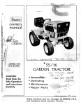
CONGRATULATIONS on your purchase of a Sears ST/ 12
Garden Tractor. It has been designed, engineered and manu·
factured to give you dependability and performance. Should
you experience any problem you cannot easily remedy,
please contact your nearest Sears, Roebuck and Co. o r Simp·
sons Sears Limited store. They have competent, well-trained
technicians and t he proper tools and parts to serv ice or repair
this unit.
•
another free manual from www.searstractormanuals.com
Please read and re tain t his manual. The instructions will enable
you to assemble, operate and maintain your Tractor properly .
Always observe the "RULES FOR SAFE OPER ATION" .
YOUR NEW
ST/12 GARDEN TRACTOR
FEATURES ...
CRAFTSMAN CAST-IRON 12 H.P. ENGINE--cool-running
performance and long life with plenty of power to take on a
variety of yard, gardening or snow removal tasks.
YARD CARE
SAFETY I NTER LOCK SYSTEM--allows engin e to start only
w hen tractor Clutch-Brake Pedal is depressed and Attachment
Cl utch Lever is in " OFF" position.
ALL GEAR TRANSMI SSION--six speeds forward, two reverse
speeds--to let you select the proper match for the terrain and
the job. Auto-type differential helps guard against turf scuffing.
CONTRC'L PANEL--with Throttle, Choke, Light Switch, Ignition Switch and Ammeter conveniently grouped for ease of
use.
GARDENS
ATTACHMEN T VERSATI LITY--handles a large vari ety of
Sears Yard and Garden Tractor A ttachments including . . .
42 AND 48 INCH MOWERS w ith three " high-lift" blades
to stand grass up for level cuts.
LITTER WHI SK LAWN SWEEPER is more efficient than
convent•onal l9wn sweepers because of its w heel-less design;
only t he rota ry- brush touche s the ground.
SELF POWERED ROTO SPADER prepares soil for new
lawns an garde~s w1 th a 30 to 38 inch wide tilling path.
OTHER SOIL T ~LAG E ATTACHMENTS including Plow,
Disc Ha1 row, Or, ;j Harrow and Cultivator.
CHEVRON T l RES for added traction in loose soil, gravel
o r snow.
SN,OW BLOWER jlandles wet, heavy or powdery snow with
ease.
SNOW REMOVAL
~
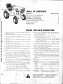
TABLE OF CONTENTS
WARRANTY
INSERT SHEET
RULES FOR SAFE OPERATION
1
EMBL Y INSTRUCTIONS
2
4
another free manual from www.searstractormanuals.com
MAINTENANCE INSTRUCTIO NS.
~
6
TROUBLE SHOOTING
11
REPAIR PARTS .
12
RULES FOR SAFE OPERATION
1. Know th e controls and how to stop quick ly . READ TH E
OWNER'S MANUA L .
2. Do not allow chi ldren to operate the vehicle. Do not allow
adu lts to operate it w i thou t prope r instruction.
3. Do not carry passengers. Keep chi ldren and pets a sa fe distance away.
4 . Clear the work area of objects which might be picked up
and thrown.
5. Disengage al l attachment clutches and shift into neutral be·
fore attempting to start the engine.
6. Disengage power to attachments and stop the engine before leaving the operator 's positior>.
7. D isengage power to attachments and stop the engine before
making any repa irs or adjustments.
8. D isengage power t o attachments when transportin g or not
in use.
\
9. Take all possible precautions w hen leaving the veh icle unattended, such as disengaging the power'< take-off, lowering
the attachments, shifting into neutraD, setting the park ing
brake, stopping the engine, and remov ing t h key .
10. Do no t stop or start sudden ly when~~ ' ing upn i ll or downhill. Mow up and down the face of sk ,)es (not ·greater than
15°); never across the face.
J
11. Reduce speed on slopes and make turns gradually to prevent tipping or loss of control. Exel·cise extreme caution
when changing direction on slopes.
12. Stay alert for holes in the terrain and o·. [Jr hidden hazards.
13. Use care when pul ling loads or using hea-vy equipment.
a. Use only approved drawbar hitch ~point£-;1
'
.
b. Limi t loads to those :YOU ce'an safely control.
c. Do not turn sharply. Use care when backing.
d. Use counterweights o ~whee l .weights when suggested in
this owner's manual.
·c
14. Watch out for t raffic when crossing o r near roadways.
15. When using any attachments, never direct discharge of
material toward bystanders nor allow anyone near the ve·
hicle whi le in operation.
16. Handle gasoline with care · it is highly fl ammable.
a. Use approved gasoline conta iner.
b . Never remove the cap of the fu el tank or add gasoline to
a r(.;n ning or hot engine, or fil l the fuel tank indoors.
Wipe up spi lled gaso line.
c. Open doors if the engine is run in the garage · exhaust
fumes are dangerous. Do not run the engine indoors.
17. Keep the vehicle and attachments in good operating con ·
dition, and keep safety devices in place.
18. Keep all nuts, bolts and screws t ight to be sure the eq ui pment is in safe working condition.
19. Never store the equipment w ith gasoline in th e tank inside
a building w here fumes may reach an open f lame or spark.
A llow th e engine to cool before stor ing in any encl osur~.
20. To reduce fire hazard, keep th e engine f ree o f grass, leaves,
or excessive grease.
21 . The vehicle and attachments should be stopped and inspect·
ed for damage after stri k ing a fo reign object, and the damage should be repa ired before restar tin g and operating t he
eq uipment.
22. Do not change the engi ne governor settings or overspeed
the engine.
23. When using the vehicle with mower, proceed as fo llows:
(1 )Mow only in dayli gh t or in good artificial ligh t.
(2)Nev<· r
::utting height adjustment w hi le the engine
is_,. n
the operator must dismount t o do so.
(3)Shut
,ne off w hen re moving the grass catcher or
unclo· ··!:! chute.
._
(4)Cbeck · '-~e blade mounting bolts fors,proper t ightness at
f reflue•
1tervals.
!•
•
24. Check the
ss catcher bags frequently for~ear or deteriorat ion. Rep
~i\h new bags fo r safety protection .
...
t ·'(
LOOK FOR THIS SYI'11BOL T9 POINT,OUT IMPORTANT
SAFETY PRECAUTit.
·• .Jlf: ANS .. ATTENT ION!
BECOME ALERT! YOUR .:iAFE'TY IS INVOLVED .
.I
. 1.
--
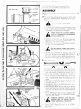
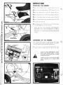
CUT AWAY VIEW
~ VENT CAP
~ WASHER
BA TT ERY
TUBE
----"'
--
To assemble and adjust your T rac tor yo u w i ll need:
one 7' 16". 9 16", and 3/ 4 Open or Box End Wrench
ASSEMBLY
1. Remove
Shipping Wires, Battery, Steering Wheel and Bag of
Parts.
u
2. Filing and charging Battery
(before installing) : NOTE : SEE
DETA I LED IN ST RUCTI ONS PACKAG ED WITH BAT ·
TE RY.
another free manual from www.searstractormanuals.com
A
a. F I Battery with electiOivte to bottoms of tubes in cells
( Frg. 1 ). NOTE : DO NOT OVERFILL. OVERFI L L ING
WI LL RESULT IN DAMAGE TO TRACTOR.
A
WASH HANDS OR CLOTHING IMMEDIATELY IF ACCIDENTA LLY IN CONTACT
WITH ELECTROLYTE .
b. Check level of electroly te after 30 minutes. Add addi ·
tiona! electrolyte if necessary. NOT E: Tighten vent
caps securr 'r. \·. th washers tn place.
c. Charge Battery at a rat e not exceeding th ree amperes
for about two and one half hours .
A
~
DO NOT SMOKE. FUMES FROM CHARG·
ED ELECTROLYTE ARE EXPLOS IVE .
d. Neutralize excess electrolyte for disposal by adding it to
fou r inches o f water in a fi ve gallon plastic con t ainer .
Stir with a wooden or plastic paddle while adding bak·
ing soda until t he addition o f mo re soda cau ses no more
foaming.
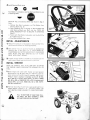
3 . Install
"
Battery using
~u
Battery Clamp, two Wmg 1\luts, two Battery Bo lts,
0
•
A
.
..._....)
,
0
two Flat Washers and two Hex Nuts found in Bag o ' Pa·;s.
a. Push down and sl ightly sprea d rear sides of Hood to re·
lease Hood Latches. Lift Hood from rear sides (F·g. 2 1.
b. Remove tape from Plastic Tray and move it slrght ly to
the right to hook one Battery Bolt int o the slot on the
left side o f the Battery Support (Fig. 3). Return Plast ic
T ray to original position (drain hole to operators R.H.
front).
c. Place Batt ery in Plastic Tray (Battery Terminals to rear
of Tractor) ( Fi g. 3).
d. Fasten Battery Clamp to installed Ba ttery Bolt w ith a
Flat Washer and Wing Nut.
e. Hook remaining Battery Bol t to right side of Battery
Support and fast en Battery Clamp to it with remaining
Flat Washer and Win g Nut (Fig. 4) . Tighten Wi ng Nuts
securely.
f. Connect RED Battery Cable to Positive(+) Bat ter y Ter·
minal with Hex Nut ( Fig. 5). Tighten Nut securely.
Place Boot over Terminal.
•
-r·:.
WEAR EYE AND FACE SH IELD.
POSITIVE T ERMINAL MUST BE CONNECTED FIRST TO PREVENT SPARKS
FROM ACCIDENTAL GROUNDING .
g. Connect B LACK Gro und Cable to Negative (-) Battery
Tern.,a with remaining Hex Nut ( Fig. 5). Tighten
Nut securely.
&
4 .1nstall Steering Wheel using:
c
0
Flat Washer, Lockwasher, and Hex Bolt assembled on end
of Steering Shaft;
another free manual from www.searstractormanuals.com
Woodruff Key, and Steering Wheel Cap found in Bag of
Parts.
a. Remove Hex Bolt , Lockwash er and Flat Washer from
Steering Shaft (Fig. 6).
b. Insert Woodruff Key in Keyway of Steer ing Shaft and
sl ide Steering Wheel over Shaft an d Key . NOTE: BE
SURE WOODRUFF KEY IS SECURE IN STEERING
SHAFT.
c. Fasten w ith Flat Washer, Lockwasher and Hex Bolt (F ig.
6). Tighten securely .
d. Press Steering Wheel Cap in place.
INITIAL ADJUSTMENTS
1. Reduce T ire pressure to 12 pounds
in fron t and rear T ires.
(Tires were overin f lated for sh ipping purposes).
2. Seat
position may be dtlj ust ecl forwa rd or backward by
loosening Nut in Seat Plate ( Fig. 7). NOT E WHEN RE·
TIGHTENING NUT AFTER AD JUSTM EN T, M AKE SURE
SEAT PLAT E HAS NOT TWIST ED OUT OF A L IGN·
MENT WITH SEAT SPRING.
3. A
spar k arrestor mu f fl er is avai lable as an accessory part f or
your tractor . Check leqalr equiremen ts in yo ur area .
INITIAL SERVICE
NOTE: BE CAREFUL NOT TO ALLOW Dl RT TO ENTER
THE ENGINE WHEN CHECKING OR ADDING 01 L OR
FUEL.
1 .Check Engine Oil Level w ith Tract or on level ground.
Wipe dipst ick (Fig. 8) clean , push i t in t ight fo r a few seconds, remove an d read Oi l Lev.el. If necessary, add Oil until
"FULL" mark is reached. In summer use S.A. E. 30 (SC,
SD or SEJ Oil. In winter (below 32°F.) use S.A.E. 10W30
(SC, SD or SE) or 10W40 (SC, SO or SE). In extreme cold
(below 0°F.) use S.A.E. 5W20 (SC, SD or SE). NOTE:
DO NOT OVERFILL.
2. Fi ll
Fuel Tan k (Fig. 7) with f res h regular grade lead-free or
leaded gasoline . Capacity is 3 · 1/ 4 gallons. NOTE : DO
NOT SWITCH FROM LEADED TO LEAD-FREE GASO LINE .
FILL TO BOTTOM OF GAS TANK FILL·
ER NECK. DO NOT OVERFILL. WIPE
OFF ANY SPILLE D OIL OR FUEL.
.
. 3-
. . ..'
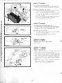
OPERATION
STARTI NG THE ENGINE
1. P ace Parking Brake Lever in locked
position (Fig. 9).
2. Prace
Anachmen t Clutch Lever in "oFF" position (Fig. 1OJ.
3. Place
Gear Shift Lever in neutral "N " posit ion (F ig. 11 ).
another free manual from www.searstractormanuals.com
4. Move Range Shift Lever to " N " neutral position (Fig. 11).
5. Pusll
Clutch-Brake Pedal into brake position (Fig. 12).
6. Move
Throttle Control Lever to middle position (F ig. 13).
7. Pull
Choke out (Fig. 13).
8 . Turn
Ignition Key to "START" position unti l Engine sta rts
(Fig. 13) . Release key into "oN" position.
NOTE: DO NOT RUN STARTE R CONTI NUOUSLY
FOR MORE THAN THIRTY SECONDS AT A TI ME. If
engme does not start after several attempts, move throttle
Control Lever to " FAST" position, wait a few minut es, and
try aga in.
ATTACHMENT
CLUTCH LEVER
WARMING UP THE ENGINE
FIGURE 10
Move Throttle Control Lever to slow position . Push Choke
in as engine warms. NOT E: ALLOW ENGINE TO WARM
UP FOR A F EW M INUTES BEFORE OPER A TING.
When restarting a warm engine, move Throt t le Control Lever
in middle posit•on , Choke may not have to be used.
ALWAYS WEAR SUBST AN TIAL FOOT·
WEAR AND AVO ID LOOSE
FITTING
CLOTHING TH A T COU LD GET CAUG HT
IN MOVING PARTS.
LEARN TO STAR T, STO P AND REV ERSE
YOUR TRACT OR IN A LA RG E, OPEN
SPA CE.
CLUTCH BRAKE
PEDAL
c
TRACTOR OPERATION
1. With
engine running and warm, place Throttle Lever in
middle posit ion.
~
2. Push
Gear Shift Lever t o "2ND" and Range Shift Lever to
"LOW".
4 . Release Parking Brake.
another free manual from www.searstractormanuals.com
1. Choose
one of the lowest gears BEFORE starting up or
down hills.
Clutch-Brake Pedal down to brake position.
3. Move
i
TRACTOR OPERATION ON HILLS
DO NOT DRIVE UP OR DOWN HILLS
WI TH SLOPES GREATER THAN 15°, AND
DO NOT DRIVE ACROSS ANY SLOPE .
2 .Avoid shifting or stopping on hi lls.
5. Release
Clutch-Brake Pedal SLOWLY to start forward
movement.
6. If ground t ravel is too slow move Throttle
Lever to fast posit ion or press Clutch-Brake peda l and shift to a different
gear. NOTE: ALWAYS SELECT A GROUND TRAVEL
SPEED THAT WILL SUIT THE TERRAIN AND THE
A T TACHMENT BEING USED.
BRING TRACTOR TO COMPLETE
BEFORE SHIFTING GEARS.
a. If slowing is necessary, move Throttle Control to middle
posit ion.
b. If stopping is necessary, push Clutch-Brake Pedal quickly to brake positio n t o preven t rolling.
c. Engage Park ing Brake and shi ft t o lowest speed rang2.
d . Partial ly release Clutch-Brake Pedal (unti l forward movement begins.
e. Release Parking Brake.
f . Complet ely rel ease Clut ch-Brake Pedal.
~TOP
3 .Make all t urns gra dually.
NEVER PLACE YOUR HANDS OR FEET
IN OR UNDE R AN Y POWERED ATTACHMENT OR NEA R ANY MOVING PART
WHILE TRACTOR OR A N Y POWE RED
ATTACHMENT IS RUNNIN G.
STARTING YOUR TRACTOR
WITH A LOW BATTERY
STOPPING YOUR TRACTOR
1. Reduce Throttle
2 . Push
Lever to "SLOW" position .
Clut ch- Brake Pedal in to Brake positi on.
3. Re lease
Att achment Clutch .
4 . Move Gear
Shift Lever to neutral " N" .
5. Place Par king Brake in
6 . Release
"LOCK" posi t ion.
Clutch -Brake Pedal.
MAKE SURE PARK ING BRAKE WILL
HOLD TRACTOR SECURE _
7. Turn
Ign ition Key to "OF F" posi t ion.
REMOVE KEY WHEN· LEAVING TRACTOR TO PREVENT UNAUTHORIZED USE.
If your Bat ter y is t oo low t o st art the engine, it should be
re charged . If " Jumper Cables" are used fo r emergency start ing
fol low this procedure: NOTE : YOUR TRACTOR IS EQUIPPED WITH A 12 VOLT NEGAT IVE GROUNDED SYSTEM .
THE OT HE R VEHICLE M UST ALSO BE A 12 VOLT
N EGAT IVE G ROUN DED SYSTEM.
LEAD-ACID BATTERIES GENERATE EXPLOSIVE GASSES.KEEP SPARKS, FLAME,
AND SMOKING MATERIALS AWAY FROM
BATTERIES.
ALWAYS SHIELD EYES
AROUND BATTERIES.
1. Connect each end of the RED cable to t he POSITIVE(+)
terminals of each battery (tak ing ca re not t o short against
chassis).
2 . Connect one end of the B LACK cable t o the NEGATIVE
(-)terminal of " GOOD" battery .
3 .Connect t he ot her end of t he cable t o ENG IN E BLOC K
or good CHASSIS GROU ND on tractor (away fro m Gas
Tank or Battery).
4.Disconnect cables in reverse order:
a. Engine Block or chassis
b. Negative termin al of " GOOD" battery
c. Posit ive t erm ina ls
TRANSPORTING YOUR TRACTOR
For pushing or t owing your t ract or , place Gear Shift Lever
and Range Shift Lever in neutral position (Fig. 11) . NOTE :
DO NOT TOW YOUR TRACTOR FASTER THAN SIX
MILES PER HOUR.
-5-
DO NOT USE YOUR TRACTOR BATTERY TO START OTHER VEHICLES.
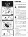
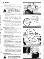
MAINTENANCE
To keep your tractor running better, longer; perform necessary
service using the following Maintenance Schedule.
Each t ime you start your tractor, check your Ammeter (Fig.
14). T he needle should move towards the + (charging) mark
indicating t he battery is being charged as you operate t he
tractor.
A
another free manual from www.searstractormanuals.com
FIRST
HOURS:
1 .CHECK V·BELTTENSION
A new V-Belt may stretch after the first few hours of opera·
tion. If Clutch-Brake Pedal, in drive position (F ig. 15). is
considerably to the front or rear of the vert ical position,
the V-Belt is out of adjustment and must be re·t ensioned.
a. Secure Clutch-Brake pedal in brake position (relaxing
V-Belt tension) by tieing to front axle.
b. Ho ld Nut on inside of Flat Idler and loosen Flat Idler
Bo lt.
c. Move Flat Idler in frame slot 1/ 4 inch down (to tighten).
up (to loosen) V -Belt tension. T ighten Bolt .
d. Release Clutch-Brake Pedal. It should return to approxi·
mately vertical position.
ENGINE
/ PULLEY
0
~
DISCONNECT SPARK PLUG WIRE TO
PREVENT ACCIDENTAL STARTING BE·
FORE MAKING ANY INSPECTION, AD·
JUST MENT (EXCEPT CARBURETOR ) OR
REPAIR .
V·BELT ~
___
. _BELT. GUARD
CHECK TO MAKE SURE TRACTOR DOES
NOT START WITHOUT FULLY DEPRES·
SING CLUTCH-BRAKE PEDAL.
NOTE : FOR LO NG ER V·BELT LIFE, ALWAYS K EEP
BELT TE NSIONED PROPERLY,
START TRACTOR '
MOVEMENT WITH T HROTTLE CONTROb IN. MIDDLE
POSITION, A ND ALWAYS REPLACE WITH SEARS
V-BEL TS.
2.CHANGE ENGINE 01 L
Changing Oil after the first two hours will help eliminate
break-in residue which might be damaging to your Engine.
Note: Be careful not to allow dirt to ente.l the Engine
J~
when changing o il.
a. Drain Oil with Engine warm. Unscrew Oil Drain Cap
(Fig. 16) and catch Oil in a suitable container. Replace
Cap.
b. Refill Engine Oil (Fig. 17). In summer use S.A.E. 30
(SC, SO or SE) Oil. In winter (below 32°F.) use S.A.E.
10W30 (SC, SO or SE) or 10W40 (SC, SO or SE). In ex·
treme cold (below 0°F.) use S.A.E. 5W20 (SC, SDor
SE). Capacity is 3 • 1/2 pints. NOTE: DO NOT OVER·
FILL.
/
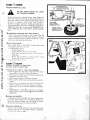
FREQUENTLY: ,..•
1. CHECK
~VENT CAP
CUT AWAY VIEW
~ WASHER
,.-,. . JJ
,
FIGUR E
18 "'-=.._-=----=----=--'--""-~
=-=-=-=-=----H
'7"
BATTERY
TUBE
BATTERY
CELL
.6.
BATTERY
a. Electrolyte solution level in each Battery Cell should be
even with bottoms of tubes in cells (Fig. 18) . Add dis·
t illed water if necessary. NOTE: DO NOT OVERF IL L.
b. Keep Battery and Terminals clean. Refer to page 10.
c. Keep Battery bo ts t gnt.
d. Keep Vent Caps t ight, Washers n place and .smal l Vent
holes in caps open.
e. Recharge SLOWLY at 3 amperes ' spec' c gravi ty of
electrolyte falls below 1.225.
2.CHECK TIRE PRESSURE
Tire pressure in fro nt and rear Tires shou ld be 12 pounds.
3 .CLEAN AIR SCREEN
A ir Screen and Guard (Fig. 20) must be kept fr ee of dirt
and chaf f to prevent Engine damage from overheating .
EVERY
HOURS:
1.CHECK ENGINE OIL LEVEL
A
another free manual from www.searstractormanuals.com
..
.
[!)
DO NOT CHECK ENGINE OIL LEVEL
WITH ENGINE RUNNING.
Several minutes after stopping Engine, check Engine Oil
Level with Tractor on level ground. Wipe dipstick (Fig. 17)
clean, push it down tight for a few seconds, remove and read
Oil Level. If necessary, add Oil until "FULL" mark is
reached. In summer use S.A.E. 30 (SC, SO or SE) Oil. In
winter (below 32°F .) use S.A. E. 1OW30 (SC, SO or SE) or
10W40 (SC, SO or SE). In extreme cold (below 0°F.) use
S.A.E. 5W20 (SC, SD or SE). NOTE: DO NOT OVER·
FILL.
STEERING
BELL CRANK
GREASE FITTING
FRONT SPINDLE
GREASE FITTING
(LEFT & RIGHT)
2. LUBRICATE STEERING AND FRONT WHEELS
There are six Grease Fittings on your Tractor (Fig. 19).
Using a Grease Gun, give each Grease Fitting two shots of
Extreme Pressure Lubricating Grease Amdex No. 1 (Avail·
able at your local Sears Service Center).
FIGURE 19
3.0IL PIVOT POINTS
Place several drops of SAE 30 Oil at points where parts
move aga inst each other, especially:
a. Idler Bearing (Fig. 15)
Remove Plastic Cap.
Remove Retainer Spri ng from Idler Shaft .
.. Move Idler and Shaft outward and lubricate exposed Shaft.
·· Return Id ler and Shaft to original posit ion, replace
Retainer Spring, and reposition Cap .
....... . b. Front Axle Pivot (Fig. 19)
EVERY~~ HOURS:
(EVERY 15 HOURS IF OPERATING
IN VERY DUSTY CONDITIONS)
1.CLEAN AIR Fl L TER & FOAM PRE-CLEANER
a. tJnscrew Wing Nut (Fi g. 20) to remove Air Filter Cover
Paper Airf.F i lter Element and Foam Pre-Cleaner.
b. Clean dust from Paper Air Filter Element by gently tap·
ping Element on a flat surface.
c. Wash Foam Pre-Cleaner in detergent and water.
d. Rinse. squeeze (rather t han twist) and allow to dry thor·
oughly.
e. Coat with three tablespoons of S.A.E. 30 Engine Oil,
knead to distribute evenly, and squeeze out excess.
f. Check Paper Air Filter Element. Replace if excessively
dirty.
•·
g. Re-Assemble Air Fi lter ' aod re-position on Tractor.
NOTE: NEVER RUN ENGINE WITH AIR CLEANER
REMOVED.
•
FIGURE 20
2.CLEAN AIR SCREEN
Air Screen and Guard (Fig. 20) must allow free -flow of air
to prevent Engine damage from overheating. Remove Air
Screen and Guard and clean with a wire brush to remove
dirt and chaff and stubborn dried gum and fibers.
3.CHANGE ENGINE OIL
The best -ime to change Engine Oil is at the end of a days
operation when all dirt and foreign material is suspended
in the hot Oil. Refer to page 6.
. 7.
;
EVERY
~(D HOURS :
1. CLEAN
ENGINE COO LI NG FINS
Remove any dust, dirt or o il from Engine Cool ing Fins
( Fig. 21 ) to prevent Engine damage from overheat ing.
2. CHECK
TRANSAX L E 01 L LE V EL
a. Block up Rear Axle securel y or use a Sears Tractor Jack.
Remove Left rear wheel by removing E-Ring.
b. Remove Fi ller Plug (Fig. 22) from Transaxle. Oi l Level
should be even with Fi ller Plug threads. Add S.A.E. 30
1\~owr Oi I if necessary.
c. Check Pressure Relief Valve (Fig. 24). It should spring
com!)letel y closed when pulled o ut by hand .
another free manual from www.searstractormanuals.com
d. Reposi t ion wheel. Secure with E·R ing.
EVERY~ffiUJ HOURS :
FI GU RE 21
1. CL EA N SPARK
PLUGS AND RESET GA P
Wi re brush carbon deposits f rom Spark Pl ug Electrodes and
reset gap at .025 inch. (F ig. 23) . Replace Spark Plugs if
they show signs of fou linQ or electrode erosion .
TRANSAXLE
FILLER PLUG
2 . LUBRICATE
BALL JO INTS
a. Move Rubber Boots to expose Ball Joints on Tie Rods
and Steering Lin k (Fig. 26).
b. Coat Bal l Joints w ith Si licone Spray Lubricant.
c. Reposi t ion Rubber Boo ts.
FIGURE 22
EVERY~liJITJ HOURS :
REPLACE PAPER A I R Fl LTER ELEM ENT
Refer t o page 7.
F IGURE 23
EVE AvfDffi[!J HOURS :
CHANGE TRANSAXLE OIL
a. Block up Rear Axle securely or use a Sears Tractor Jack.
Remove Left Rear Wheel by remo ving E· Ring.
b. Drain Transaxle Oil by removing Drain Plug (Fig. 24) and
ca t ching Oi I in suitable container . Replace Drain Plug.
c. Refi ll Transaxle wi th S.A.E. 30 Moto r Oil. Capacity is 5
quarts. Pressure Reli ef Valve (opposite o f oil f i ll side of
Transaxle) may be held open to allow Transaxle to til ! more
quick ly.
d. Check Pressure Relief Valve. It should spring completely
closed when pulled o ut by hand and released.
e. Reposit ion wh eel. Secure wi th E-Ring .
. 8.
'<J
AS NEEDED :
1. REPLACE
I N-LI NE FUEL Fl LTER
If f uel filter is clognccJ, obstruct rng fuel flow to carburetor,
replacemen t is r equirccl.
a. With Engine cool . remove and plug Fuel L ine Sections
as removed from both ends of Fuel Fi lter (Fig. 25).
b. Place new FLrel Filter i n position in Fuel Line (arrow
on side of Filter in direction of fuel flow).
....
another free manual from www.searstractormanuals.com
....
..
A
BE SU RE THER E A RE NO FUEL LINE
L EA KS A ND TH A T FUEL LINE IS IN
PROPER POS ITION IN HOSE CLAMPS.
2. TOE-IN ADJUST MENT
If any parts in Front Axle or Steering Mechanism are being
repla ced, Tie Rod adjustment is required.
a. Loosen Jam Nuts (Fig. 26) at each end of Tie Rod Ad ·
justment Sleeves.
b. Adjust both Tie Rods so that Tie Rod Joints measure
from 10 to 10 · 1/ 8 inches from center to center.
c. Tighten Jam Nuts, making su re T ie Ro d Joi nts are parallel (180°) t o each other . This adjust ment secures
proper Front Wh ee l Toe-i n and steering operation.
3 .BRAK E ADJUS TMENT
If Clutch-Brake Pedal (Fig. 27) has more than approximately 4 inches of travel from vertical to full brake position
then brake adjustment is necessary.
a. Loosen Jam Nut (F ig. 27) in order to turn t urnbuckle
cl ockwise (from in front of t ractor ) one turn at a time
until Cl utch-Brake Pedal regains 4 rn chcs o f t ravel.
b. Tighten Jam Nut against Turnbuckle.
FI GURE 26
4 .PARKING BRAKE ADJUSTMENT
If Parking Brake will not hold tractor. Park ng Brake ad·
justment is necessary.
a. Loosen Parking Brake Hex Nuts (Fig. 27).
b. Place Parking Brake Lever in locked positron.
c. Hold Clutch -Brake Pedal in brake position and t igh ten
first Hex Nut finger tight against Bushing.
d. Rel ease Clutch -Brake Peda l and turn first Hex Nut two
turns more agarnst Bushing.
e. Tighten second Hex Nut against frrst Hex Nut.
5 .CA RBURETOR ADJUSTMENT
If Engine lacks power or does not idle properly, the Carburetor may need adjustment.
a. Main Fuel (High Speed) Screw (Fig. 28) should not require adjustment. If resetting is necessary, turn clockwise, closing finger tight ONLY, then turn counterclockwise 1 to 1 - 1/8 turn.
b. Turn Idle Adjusting Needle (Fig. 28) clockwise, closing
finger t ight ONLY, and then turn counterclockwise
3/4 to 7/8 turn.
c. Start Engine and allow to warm for f ive mintues.
d. Make final adjustments with Engine running and Gear
Shift Lever in Neutral posit ion.
-- Turn Idle Adjusting Needle counterclockwise until
Engine runs "rough" then clockwise until Engine
begins to miss. Ret urn Screw to a point midway between these· extremes.
Throttle Stop Screw (Fig. 28) should not require adjustment. If resetting is necessary, set to obt ain the
slowest engine speed that will allow smooth accelleration .
6.R E-TENSION V-BE LT
It may be occasional ly necessary to re-tension V-belt. (See
page 6.
CHECK TO MAKE SURE TRACTOR DOES
NOT START WITHOUT FU L LY DEPRESSING CLUT CH-BRAKE PEDA L.
• g.
7. CLEAN
BATTERY AND TERMINA LS
CorrosiOn and dirt on the Battery and Term ina ls cause
the Battery to " teak" power and hinders the operation of
the cnarger.
a. Remove the Bat tery from the Tractor and wash with
lour tablespoons o f bak ing soda to on e gallon of water.
~OT E . BE CARE FUL NOT TO GET THE SODA
SOLUTI ON IN TO THE CELLS. Rin se the Battery w ith
pta f"l ::ater. dry and reinst all on Tractor .
b. C ea'l terminals w ith a w ire bru sh un t il br ight. Re·
place Batter y Ca bles . Coat term inal connect ions w it h
Vaseline .
another free manual from www.searstractormanuals.com
FIGURE 29
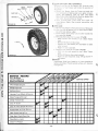
S.TIRE CARE
a. Ma main t ire pressure in f ron t and rear t ires of 12 pounds.
b. Keep tire s free of gasoline, oi l, or insect con trol chemi ·
ca ts whi ch can destroy rubber.
c. A vo1 d st umps, stones, deep ru ts and other hazards t hat
may cause t ire damage .
d . Removing front w hee l for t ire repair (Fig. 29):
·· Block up f ron t axle securely or use a Sears Tractor
Jack.
.. Remove Hex Bolt and Dust Cap .
.. Remove Nut, Wear Washer , Pi,l and Washer to allow
wheel removal.
.. Repai r tire and reassem ble .
e. Removing rear whee l for t i re repair (Fig. 30):
.. Block up rear axl e securel y or use a Sears Tractor
Jack .
Remove E-Ring to allow w heel re moval.
.. Repair t ire and reassemble. Snap E-Ring securely in
ax le groove.
9.FINISH
Keep tracto r finish free of gasol ine, oil, i nsect chemicals or
batt ery electroly te. Pro tect paint ed surfaces with Au t omo·
t ive t ype wa x.
FIGURE 30
~~~
~y.o O y.O 0~ oO~ 0~
SERVICE RECORD
FILL IN DATES
AS YOU COMPLETE
REGULAR SERVICE
.,
~--4~ ~--4'\0. ~--4~ ~--40.~
~~
Check Engine Oil Level
~
IV
IV
Oil Pivot Points
Lubricate Front Wheels & Steer ing
~
Check Transaxle Oil Level
Change Transaxle Oil
IV'
Clean Air Filter & Foam Pre -Cleaner
Replace Paper A ir Filter Element
Oean Engine Cooling Fins
Clean Spark Plug & Reset Gap
Check Battery Levels
Check T ire Pressure
~-..l~
IV
Change Engine Oil
Clean A1 r Screen
~-..l~
~
""'l.,
~
:V
. 10.
v
""'
-..l~
SERVICE DATES
~
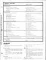
TROUBLE SHOOTING
POSSIBLE CAUSE
POSSIBLE REMED Y
WI LL NOT START
Clut ch-Brake Pedal in drive posit ion
Atta chment Clutch Lever in "ON " position
No gasolme in Fuel Tank, clogged Fuel Filter
or Fuel Line
Blown Fuse
Dead Battery
Press Pedal into brake posrtion
Move Lever to "OF F" oo~rtron
Frll Tank with Gasoline. Check Fuel Line, Fuel Frlter
and Carburetor {clean f necessary)
Check for fault and replace Fuse
Recharge or replace Battery
another free manual from www.searstractormanuals.com
HARD TO START
Choked imprope rly, flooded Engine
Clogged Fuel Filter
Clogged Fuel Tank
Dirty Au Cleaner
Spark Plug d irty or improper gap
Defective Battery
Defective Ignition or loose w ir ing
Water in gasoline or o ld fLrc l
Improper Carburetor adjustment
Push Choke in, place Throt le Control in middle posi
tion and run starter s~~eral times to clear out gas
Remove and replace
Remove and clea"
Remove and clear
Clean, adjust gao or reolact>
Recharge or rep,ace
Check the wmng and Spark Plug
Drain Fuel Tank and Carburetor, use fresh fuel and
clean Spark Plug
Make necessary adjustments
ENGINE MISSES OR LACKS POWER
Engine overload
Clogged Fuel Frlter
Clogged Fuel Tank
Partially plugged Air Cleaner
Improper Carburetor adjustment
Dirt y Air Scr ccn
Lo w orl level or dirty o il
Spark Plug dirty, improper gap or wrong type
Faulty qn t on
Poor compr essron
Orl rn gasoline
Shrft to a lower gear or reduce load
Remove and rep lace
Remove and clean
Remove and clean
Makn necessary ad justments
Clean A ir Screen and Cyll ncler Fins
Add or change oil
Clean, reset gap or replacP
Check Spark Plug and for loose wires
Major Engine overhaul
Drarn and refill Gas Tank and Carburetor
ENGINE OVERHEATS
Dirty A rr Screen
Low orl levL or duty oil
Dirty Engrne
Partral y plugged iiJu" er
Partrally pluqqed Air Cleaner
Stale fuel or rmproper Carbwetor adjustment
Clean A11 Screen
A dd or change o il
Clean Cylinder Fins
Remove and clean Muffler
Remove and clean
Usc fr esh fuel and adjust Carburetor
NO LIGHTS
No Headlrghts o r Tailligh t w ith Ligh t Switch Knob
pull ed out
Check Light Fuse under cl ash, replace Tai ll ight Bu lb
or Sealed Beam Headlights
WON'T CHARGE
Blown Fuse
Defective Battery
Check for fault and replace
Replace
STORAGE
1. ENGINE
OI L
Drain (with engine warm) and replace w ith clean engine oil.
Refer to page 6 .
2 .FUEL SYSTEM
a. Drain fuel tank and carburetor by allowing the engine to
run out of gasoline. NOTE : GASOLINE LEFT IN YOUR
ENGINE WILL LEAVE GUM DEPOSITS CLOGGI NG
FUEL SYSTEM.
b. Dispose of gasoline if not to be used. NOTE : GASO·
LINE STORFD FOR SEVERAL MONTHS LOSES
ITS VOLATILITY (ABILITY TO BURN EFFECT·
IVELY).
c. Tu rn ignrtron key to "START" position for a few
seconds to distr'bute orl.
d. Replace Spark Plug.
4.BATTERY
a. Remove battery if t ractor rs not used regularly during
winter months. Store in cool, dry place (above 50°F).
NOT E: DO NOT STORE BATTERY DIR ECT LY ON
CEMENT SURFACE.
b. Check electrolyte charge each month and recharge if
below 1.225 specific gravity. NOTE : BATTER I ES NOT
IN USE FOR SE VERAL MONTHS A ND NOT KEPT
FULLY CHARGED, PRODUCE SULPHUR DEPOSITS
ON PLATES WHICH CANNOT BE REMOVED BY
RECHARGING.
3 .CY LINDER
a. Remove Spark Plug.
b. Pour one ounce of o il through spark plug hole int o cy·
S. GENERAL CLEANING
Iinder.
. 11 .
Clean engine, battery, finish , etc. of all foreign matter.
......
~----
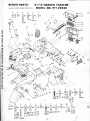
REPAIR PARTS:
MAIN FRAME . DASH AND GRILL
A
B
~ ~~
u:n 80
C
lf81
72A
Gts
0
ST/ 12-GARDEN TRACTOR
MODEL NO. 917.25930
E
,.2 !::!::
____ ,
F
2
._-- 3
':..1 .....
\.#":~~l~
CI§I)83
--5
=~
71
\
73
7~ ~
another free manual from www.searstractormanuals.com
3
\1 \
v-<
G
K
J
1
116
CfiP
~
117
V 88
79
=
L
M
'1ii
I
113c:s::, 96 = 78
tn) 114
[])93 =
92 g l94
~ 95
91
~96
~
~86
[]) 93
p
R
Q
S
99
( [ ] 97
=
98
~~:
.,.
T
V
W
X
Y
Z
AA
BB
CC
~95 Oji\ o1 ~1o3T1o4 11osCS\o6~108 lf110 tl~~~ ,
t:::IC:> 96
1 I
C
=98
~96~86 c:s:::> 96
([] 97[]) 93 []) 97
[J) 97 ~100
98
I
~96 ~107(@])109
[1)97
. 12 .
11.1
115
~ 113 = 78
IIIJ 114 <=:~= 79
rr:n 80
I
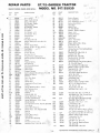
REPAIR PARTS:
MAIN FR AM E, DASH AND GR ILL
KEY
NO .
another free manual from www.searstractormanuals.com
~
1
PART
NO .
ST/ 12-GARDEN TRACTOR
MODEL NO. 917. 25930
DESCRIPTION
~ (:,·
Gri ll - Upp_y )
2 - r91f1 R
Decal - Gri ll (ST/ 12)
3
7995R
Decal - Hood Strip
5
2672R
Grill Screen · Upper
6
8768H
Mounting Clip
7
2794R
Grill Screen · Center
8
7937R
Gri ll- Lower
9
7938R
Grill Stde
10
2674R
Grill Screen · L.H.
11
2673R
Gril l Screen · R.H.
12
6253R
Exhaust Pipe
13
9540H
Locknut
14 504P
• HexNut5/16- 18
15
663A149
Muffl er Clamp (Inc. Key No. 14)
17
7820R
Muff ler
19
634A710
Muffler Guard Ass'y.
20
_1537.!P_ _ _'Washer 11/ 32x 11 / 16 ~ 16Ga.
/ 21
7811 R
Grill Cable_.
1 l. 9 i
22 - l 899R
Grill Brace
23
634A771
Engine 12 H.P.
24
9396E
Sq. Key 1/4 x 2
2G
634A 104
Engine Pulley w/Set Screws
27
634A792
Mounting Plate and Guide Ass'y.
28
8704H 1
SiJacer
29
4939M
Retainer Spr ing
30
9011 H
Belt Retainer
31
634A660
Belt Guard Weldment
32
8238H
SiJiit Spocer
36
634A820
Hood Latch
•
SuiJiJOrt Bumper
37
8457R
Battery Support Bracket (Inc. Key 39)
38
634A818
3RA
?514P
*Cotter Pin 1/4 x 1
Bearing
39
7756R
Cap· Idler Shaft
40
8006R
Cover· R.H.
41
7905R
Handle Grip
42
4379H
Atta chment Clutch Lever
43
7945R
E-R ing
44
5002P
Hanger Weldmf>nt R .H. · Front
45
634A785
Belt Tightener Arm
46
7944R
Return SiJring
47
7948R
Bush ing
47A
2248R
48
7810H
Locknut 3/8 - 24
49
634A814
Hanger Weldment · Rear
Drawbar and Weldnuts
50
634A787
Hanger Weldment · L.H. - Fron t
51
634A355
52
7929R
Choke Control
53
7932R
Throttle Control ( Inc. Key 61, 62 & 63)
Dr ive Rivet
54
9521 H
55
7939R
Decal (Shift Pa ttern )
56
634A78 1
Chassis Ass'y. (Inc. Key 57 & 58)
Bearing
57
6468H
Bearing
58
4766H
59
634A782
Engine Mount Ass'y.
59A
7907R
Panel Brace
Throttle Wire & Casing
6·1
8205R
Clamp
62
8204R
Throttle Control Lever
63
8203!-1
Dashboard (Inc. Key 66 & 67 1
64
634A822
2676R
KEY
NO.
PART
NO.
65
66
67
68
69
70
71
72
72A
73
74
75
76
77
78
79
80
81
8527R
1998R
8571 R
7912R
7874R
8630R
704R
7731 R
8023R
7835R
3300R
634A700
8028R
8057 R
1506P
1002P
503P
5554P
82
83
84
85
86
87
3322P
1605H
3003P
3010P
1003P
5501 P
88
91
92
93
94
31 14P
1537P
3011P
504P
4514P
95
96
97
98
99
3023P
1004P
501P
1513P
31 54P
100
101
347H
3012P
103
104
3137P
5557P
105
61P
106
107
108
109
110
3035P
1001 P
3021P
5394H
6055P
11 1
112
113
114
115
116
53P
1535P
1006P
505P
3114P
3073P
117
3022P
. 13.
DESCRIPTION
sJ: w" ~"
T?
Battery Support
~ C: f\
Clip · Dashboard
/
Cl ip . Dashboard. Cente• f
pel~
Battery Heat Shield
Hood Seal
Battery Tray
A ir Inlet Screen
Bracket - Battery Support
Cover· L.H.
Bracke t Rectifier
Decal · Sears
Hood Ass'v.
Decal · Instruction
Decal · Wiring
' Washer 9/32 x 5/ 8 x 16 Ga.
• Lockwasher 1/ 4
'Hex Nut 1/ 4 · 20
Phillips Pan Hd. Thd. Cutting Screw
10 - 16x1 / 2
* Hex Bolt 1/ 4 · 20 x 2 Gr. 5
Locknut 1/4 · 20
'Hex Bolt 1/4 · 20 x 3/4
'Hex Bolt 5/16 · 18 x 3/ 4
• Lockwasher 5/16
Phill ips Pan Hd. Thd. Cutting Screw
10 · 24 x 3/8 Type T
* Fin. Hex Bo lt 1/4 · 20 x 1/2
•washer 11 /32 x 11116 x 16 Ga.
•Hex Bolt 5/1 6 · 18 x 1
'Hex Nttt 5/ 16 · 18
Hex Socket Hdless Set Screw
5/ 16 · 18 X 5/ 8
'Hex Bolt 3/8 · 16 x 1
• Lock washer 3/ 8
*Hex Nut 3/8 · 16
• w asher 13/ 32 x 13/ 16 x 16 Ga.
Sit. Fi l. Hd. Machine Screw
1/4-20x2- 1/4
Huglock Nut 1/4 · 20
'Hex Bolt 5/ 16 · 18 x 1 · 1/ 4
f.
CutJ (
·Hex Bolt 3/8 · 16 x 1 -1 /4 Gr. 5
Hex Washer Hd . Thd. Cutting Screw
1/4- 20 x 1/ 2 Type 1
"Sq. Neck Short Shoulder Carriage
Bolt3/8-16x1Gr.5
*Hex Bolt 7/ 16 · 14 x 1 · 1/ 4
• Lockwasher 7/16
'Hex Bolt 3/ 8 · 16 x 3/ 4
Locknut 3/8 · 16
Hex Sit. Hd. Machine Screw w/Scms
Int. Tooth Lockwasher 10 · 32 x 1/ 4
·Sq. Neck Carriage Bolt 10 · 24 x 112
•washer 7/ 32 x 7/ 16 x 18 Ga.
• Lockwasher No. 10
· Hex Nut 10 · 24
· Hex Bolt 1/4 · 20 x 1/ 2
*Sit. Truss Hd . Mach ine Screw
10 - 24x1 / 2
*Hex Bolt 3/8 • 16 x 7/8
*STANDARD HARDWARE--PURCHASE LOCALLY
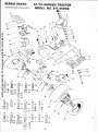
REPAIR PARTS:
ST/12-GARDEN TRACTOR
MODEL NO. 917.25930
STEERING AND FINAL DRIVE
••
-
1
~2
®------3
®-=:-----.: 4
42
5
42
'(T
41
39
another free manual from www.searstractormanuals.com
43
~7
~8
~7
e ..
-
45
9A
9
26
K
~61
~
CIIl
M
CIIJ
71
72
<::S=>
(riJ
l
'
=
=
63
64
64
61 ~ 65
62 cr::Il 66
R
i
67
68
a::Il 69
...,
v
I•• I y I\· I ·
p
N
~ 10 173
=
~~
~6
a
74
52
~52
53
(riJ 53
c::=
c::S=J
[Q)
T
56
c::s:::> 57
75
76
77
78
s
c::s:::> 57
C@D 49
- 14 -
23
22
-./
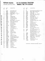
REPAIR PARTS:
STEERING, AND FINAL DRIVE
another free manual from www.searstractormanuals.com
KEY
NO.
1
2
3
4_
( 5_
6
7
8
9
9A
10
11
12
13
14
15
16
17
18
19
20
21
22
23
24
25
26
27
28
29
30
31
32
33
34
35
36
37
' 38 39
40
41
42
43
44
45
PART
NO.
ST/12 - GARDEN TRACTOR
MODEL NO. 917.25930
DESCRIPTION
7879R
Steering Wheel Insert
3023P
"Hex Bolt 3/8 · 16 x 1
* Lockwasher 3/ 8
1004P
1559f._
~ash~/16 x 1 x 10 Ga . .:lc.
7893R
__ ~eering Wheel~
5003P
E-Ring
Cap
9007H
5949H
Rubber Bushing
7903R
Foot Rest- L.H.
7999R
Decal (Clutch-Brake)
Decal (Attach. Clutch)
7998R
7904R
Foot Rest - R.H.
1552P
*Washer 49/64 x 1 - 1 /4 x 16 Ga.
9858M 1
*Woodruff Key 3/16 x 5/8
634A775
Steering Shaft and Pinion
7987R
Control Knob
Shift Rod Bracket
6442H
2511P
*CotterPin 3/16 x 1
634A22A
Belt Guide
6477H
Range Shift Rod
6459H
Transmission Bracket
8357R
Fuel Tank Pad
8246R
Rear T ire 23 x 8.50 - 12
795R
Tire Valve
2893R
Rear Wheel
8186R
Fender- R.H.
634A692
Wheel Hub - Rear
7563R
Axle Thrust Washer
5845R
E-Ring
Fender- L.H.
8187R
2656R
Bracket - Tail Light
634A823
Seat Stop and Bracket
634A824
Fuel Tank Retainer and Pads
8141 H
Seat Spring Reinforcement
Seat Spring
7898R
634A776
Seat Plate Weldment
Seat Bracket Weldment
634A532
___Bracket Seat Pivot ~
7897R
_ 7934R __Seat J''
~
1
7886R
Fuel Gauge
7885R
Fuel Tank
6999R
Hose Clamp
2751 R
Clip- Fuel Line
Fuel Line
8373R
7741R
Fuel Filter
7895R
Steering Shaft Spacer
if-]· I/
KEY
NO.
PART
NO.
46
47
48
49
50
51
52
53
54
55
56
57
58
59
60
61
62
63
64
65
66
67
61P
1513P
1519P
5394H
3137P
1557P
1004P
501P
3252P
3022P
3010P
1003P
19P
1304H
3034P
1001P
500P
3003P
1506P
1002P
503P
3074P
68
69
70
1404P
505P
5P
71
1537P
1685H
3021P
25P
1578P
1560P
1000P
502P
3159P
7880R
72
73
74
75
76
77
78
79
DESCRIPT ION
*Sq. Nk. Sht. Shld. Carr. Bolt 3/8- 16 x 1 Gr. 5
'Washer 13/32 x 13/16 x 16 Ga.
*Washer 15/ 32 x 1 x 12 Ga.
Locknut 3/8
*Hex Bolt 3/8 - 16 x 1 · 1/4 Gr. 5
*Washer 13/32 x 13/ 16 x 11 Ga.
* Lockwasher 3/8
*Hex Nut 3/8 - 16
"Hex Bolt 3/8- 16 x 1- 1/2
*Hex Bolt 3/8 - 16 x 7/8
*Hex Bolt 5/16 - 18 x 3/4
*Lock washer 5/16
'Sq. Neck Carriage Bolt 3/ 8 - 16 x 3/ 4
Hub Bolt
*Hex Bolt 7/16- 14 x 1
• Lockwasher 7/ 16
*Hex Nut 7/16- 14
*Hex Bolt 1/4- 20 x 3/4
*Washer 9/ 32 x 5/ 8 x 16 Ga.
• Lockwasher 1/ 4
*Hex Nut 1/4 - 20
*Sitd. Truss Hd. Machine Screw
10 · 24 X 3/4
*Ext. Tooth Lockwasher No. 10
"Hex Nut No. 10- 24
*Short Shoulder Sq. Neck Carriage
Bolt 5/16 - 18 x 3/4
"Washer 11/32 x 11/16 x 16 Ga.
Lock Nut 5/ 16 - 18
*Hex Bolt 3/8 - 16 x 3/4
"Carriage Bolt 1/2 - 13 x 1 - 1/4 Gr. 5
"Washer 3/4 x 1 - 1 - 1/8 x 11 Ga.
*Washer 17/32 x 1 - 1/2 x 11 Ga.
" Lockwasher 1/2
*Hex Nut 1/2 - 13
*Hex Bolt 5/ 16 - 18 x 7/8
Owners Manual
71
"STANDARD HARDWARE--PURCHASE LOCALLY
- 15-
REPAIR PARTS:
another free manual from www.searstractormanuals.com
BRAKE AND CLUTCH
ST/12-GARDEN TRACTOR
MODEL NO. 917.25930
22
37
38
B
c
D
E
F
G
- 16 -
H
J
REPAIR PARTS:
BRAKE A ND CLUTCH
PART
NO.
KEY
NO.
ST/12-GARDEN TRACTOR
MODEL NO. 917.25930
DESCRIPTION
another free manual from www.searstractormanuals.com
'Z"Fo;..otPe~r.-...~
;c
~
4
5
6
7
8
9
10
11
12
14
15
16
17
18
19
20
21
22
23
24
25
26
27
28
29
30
31
32
33
34
35
36
-
8156H _ _
9008H
Spring
634A757
Foot Pedal Shaft Weldment
5001 P
E-Ring
1527P
*Washer 21 /32 x 7/8 x 16 Ga.
2505P
*Cotter Pin 1/8 x 3/ 4
2202R
Brake Rod- Front
6417H
Turnbuckle
501P
*Hex Nut 3/8 - 16
7823R
Safety Start Actuator
2201 R
1557P
2263R
2197R
175H
634A489
2221 R
5999H
4379H
626A341
7810H
626A365
634A167
634A168
9204H
7648H1
634A33A
9858M1
2645R
2514P
6486H
1545P
4939M
Bushing
*Washer 13/32 x 13/16 x 11 Ga.
Spring Washer
Parking Brake Yoke
Roll Pin
Lock Bracket Assembly
Parking Brake Spacer
Spring Washer
Handle Grip
Parking Lock Hand le Assembly
Gripco Centerlock Nut 3/8 - 24
Brake Rod Assembly
Brake Band and Lining
Brake Bracket Assembly
Lock Nut 1/ 2- 20
Brake Drum
Brake Arm Assembly
Woodruff Key
Clutch Rod
* Cotter Pin 1/ 4 x 1
Spring
*Washer 17/32 x 1 x 16 Ga.
Retainer Spring
KEY
NO .
PART
NO.
37
38
39
40
41
42
43
44
45
46
47
48
49
52
53
54
55
56
57
58
634A754
634A86
5002P
626A31A
500P
1001P
1518P
6635H
1520P
6479H1
3262P
59
60
61
62
63
64
65
66
67
68
..&t7..411
6461H2
3052P
1513P
548P
4501P
3022P
1004P
3164P
11 p
1002P
503P
3159P
1685H
3244P
9071H
3326P
1567P
562P
DESCRIPTION
Idler Bracket Weldment
Idler, Bolt & Nut (Inc. Key No's 52, 53 & 54)
E-R ing
Steering Arm Assembly
*Hex Nut 7/ 16·14
• Lockwasher 7/ 16
·washer 15 32 x 11 / 16 x 16 Ga.
Flat Idler
Washer .469 I.D. x 1 - 1/8 x 11 Ga.
Belt F1nger
• Hex Bolt 7/,16 · 14 x 2-1 / 2
V·Belt
\ ,_, ]J ... ~ l
Pulley, Tra-nsmission
*F in. Hex Bolt 3/8- 24 x 1
•washer 13/ 32 x 13/ 16 x 16 Ga.
• Hex Jam Locknut 3/8 - 24
*Sq . Hd. Set Screw 5/ 16- 18 x 1/ 2
*Hex Bolt 3/8 - 16 x 7/8
• Lockwasher 3/8
Flat Hd. Machine Screw - Undercut
3/8 - 16 X 3/4
*Sq. Neck Carriage Bolt 1/4 · 20 x 5/8
*Lock washer - 1/4
" Hex Nut 1/ 4-20
* Hex Bolt 5/16-18 x 7/8
Locknut 5/ 16- 18
* Hex Bolt 1/4- 28 x 5/ 8 Gr. 5
Huglock Nut 1/ 4 - 28
Hex Hd. Mach. Screw 6- 32 x 1
Flat Washer 5/ 32 x 3/8 x 20 Ga.
Center Locknut 6 - 32
*STANDARD HARDWARE--PURCHASE LOCALLY
- 17 -
REPAIR PARTS:
ST/12-GARDEN TRACTOR
MODEL NO. 917.25930
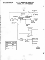
SCHEMATIC DIAGRAM
L
BATTERY
+ lj 12V
STARTER
,o----o-f
',
another free manual from www.searstractormanuals.com
NEUTRAL
/~
AMMETER
bs
PROTECTION
RESISTOR
ATTACHMENT
SAFE. SW. ,...------,
111-----....
SOLID
STATE
IGNITION
30 AMP.
IGNITION L
SWITC H
"--...... ~OLENOID
G
RECTif=IER
)
CHARGING
COIL
FUSE
/
~
15 AMP.
POSITION
CIRCUIT
OFF
M-G
RUN
B-L
START
HEADLIGHT
~~--0~------~
LIGHT
SWITCH
HEADLIGHT
TAILLIGHT
CHASSIS
GROUND
B-S
. 18.
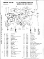
REPAIR PARTS:
ST/12-GARDEN TRACTOR
MODEL NO. 917.25930
ELECTRI CA L
1
'
another free manual from www.searstractormanuals.com
•
19
A
17
D
~ 37
y
36
[]) 38
c::c 41
'
50
a::D 42
E
a:::n 40
F
_..., 43
~ 39
cr:::D
, ..
14
c
B
~ 39
40
KEY
NO.
1
2
PART
NO.
6452R
5554P
DESCRIPTION
3
4
5
6
7
8
9
10
11
12
13
14
15
16
17
8768H
8784H1
8031R
9197H
3748M
1509P
5110H
2685R
4171R
5111H3
2235R
7755R
7754R
8027R
2226R
Headlight
Phillips Pan Hd . Thd. Cutting Screw
No.10-16x 1/2
Mounting Clip
Rubber Spacer
Headlight Ground Wire
Hose
Wing Nut 1/4 · 20
Washer 5/16 x 3/4 x 16 Ga.
Battery Clamp
Battery Bolt
Insulated Cli p
Battery
Cable · Solenoid to Starter
Safety Switch
Solenoid
Wire · Ground to Solenoid
Battery Cable
19
20
21
22
23
24
25
26
8030R
8089H
8292H
8293H
8291H
7989R
2777R
7794R
Light Harness
Tai l Light (Inc. Key No. 21, 22, 23)
Lens· Taillight
Housing - Taillight
Bulb No. 1895 2 Candle Power
Ammeter & Bracket
Tie
Light Switch Knob
13
G
K EY
NO.
27
28
29
29A
30
31
32
33
34
~§..
36
37
38
39
40
41
42
43
44
45
46
47
47A
48
49
50
-19 · 51
PA RT
NO.
7793R
2212R
6347 R
8113R
2753R
7761 R
7552 H
4406 R
7884R
7809R
5534P
1003P
538P
1002P
503P
1006P
543P
1402P
3003P
505P
1583P
3074P
8615R
1404P
1504P
311 5P
8355R
H
(D) 42
=46
c::c 41
a::D 42
a:Il40
DESCRI PTION
J
,47
=
=
48
49
49
-
48
!X:D 45
Light Switch
Fuse · 15 Am p.
Fuse· 30 Amp.
Fuse Harness
Battery Cable - Ground
Terminal Cover
Key Set
Ign it ion Switch
Main Ignit ion Harness
Regulator · Rectifier
Slotted Hex Indented Hd. Self Tapping
Screw Type 1 No. 10 · 24 x 3/8
* Lockwasher 5/ 16
*Hex Jam Nut 5/ 16 · 24
* Lockwasher 1/ 4
*Hex Nut 1/ 4 · 20
*Lockwasher No. 10
*Hex Nut No. 10 · 32
* Ext. Tooth Lockwasher 3/8
*Hex Bolt 1/ 4 · 20 x 3/ 4
*Hex Nu t No. 10-24
Brass Washer No. 10
' Si td. Truss Hd. Mach. Scr. 10 · 24 x 3/4
Clip
*Ext. Tooth Lockwasher No . 10
*Washer 7/32 x 1/ 2 x 18 Ga.
" Hex Bolt 1/ 4 · 20 x 5/8
Gasket, Battery Cap
~ STA NDARD HARDWA RE--PURCHASE LOCA L L Y
ST/1 2-GARDEN TRACTOR
MODEL NO. 917.25930
another free manual from www.searstractormanuals.com
3
7
I
'4}>
83 . . .
84-
98
-20 -
- - -
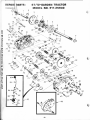
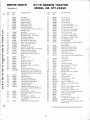
REPAIR PARTS:
another free manual from www.searstractormanuals.com
TRANSAX LE
KEY
NO.
PART
NO.
1
2
3
4
5
6
7
8
4202R
5845R
4199R
4216R
4 215R
4217R
6256H
3056P
9
10
11
12
13
14
15
16
17
18
19
20
21
22
7392M
6272H
4985R
6266H
4212R
41 96R
6276H
633A63
8118M
8740H1
6217H
4218R
6252H1
7810H
23
24
25
26
27
28
29
30
31
4986R
7393R
992R1
6216H
6262H
6215H
6269H
5855H
633A28A
32
33
34
35
36
37
38
39
6277H
4225R
7396H
4198R
4200R
7395H
6275H
633A27
40
41
45
46
47
4002P
4003P
6271 H
4001P
3087P
48
1007P
ST/12-GARDEN TRACTOR
MODEL NO. 917.25930
DESCRIPTION
Axl e Shaft
Retain ing Ring
Final Drive Gear
Differential Gear
Differential Pinion
Differential Carrier
Axl e Thrust Washer
*Hex Bolt 3/8 · 24 UNF x 3 · 1/4 (1"
Thread Length)
Steel Ball
Spring Sh ift Fork Detent
Shift Fork, High· Low Range
Thrust Bearing Race
4th Reduction Pinion
3rd Reduction Gear Shaft
Snap Ring· Crescent Type
High · Low Range Gears
Needle Bearing.
Sint ered Iron Bearing
Shift Fork Shaft, High· Low Range
Differential Pinion Spacer
Differential Pinion Bushing
*Gripco Centerlock Nut 3/8 · 24
UNF
Shift Fork· L.H .
Oil Seal
Sintered Iron Bearing
Shift Fork Shaft
Shift Fork· R.H.
Shift Shaft, High · Low Range
Oil Seal
Pressure Relief Valve
Gearcase, Reverse Idler Shaft and
Bearings· R.H . (Inc. Key No's. 17,
18, 25, 33, 50, 63, 76, 77 and 82)
Dowel Pin
Needle Bearing
Thrust Bearing Race
4th Reduction Gear Shaft
4th Reduction Gear Spacer
Thrust Bearing Race
Gearcase Gasket
Gearcase and Bearings· L.H .
(Inc. Key No's. 18, 25, 49, 50 (2),
51 and 52)
*Pipe Plug 1/ 2 · 14 N.P.T.
*Street Elbow 90°, 1/2 • 14 N.P.T.
Oil Seal
*Pipe Plug 1/ 4 · 18 N.P.T.
*Hex Bolt 5/ 16 · 18 UNC x 1· 1/2
Grade 5 H .T.
"Lock washer 5/ 16 Extra Heavy
KEY
NO.
PART
NO.
49
50
51
52
53
54
55
56
57
58
59
60
61
62
63
54
4895H
4222R
1529R
8119M
4220R
4209R
4213R
4442R
4195R
4214R
41 94R
7528R
4208R
4207R
7398H
4203R
65
66
67
68
69
70
71
4204R
9858M1
4926H
4205R
4206R
1370H
633A 11
72
73
74
75
76
77
78
79
80
81
82
83
84
85
86
87
88
89
90
91
92
93
94
95
96
97
98
4193R
4201R
5001P
1153R
7392H
5529H
504P
1167R
541P
6270H
7384H
6364H
8551 R
4869H1
633A39A
8739 H1
4924 H
1544P
8105R
1569P
633A1 9
6274H
2505P
1003P
31 59P
633A82
633A78
DESCRIPTION
Needle Beari ng
Needle Bearing
Needle Bearing
Need:e Bearing
Thrust Bearing Race
3rd Reduction Pinion · Low
4th Reduction Gear
3rd Reduction Pinion Spacer
2nd Reduction Gear Shaft
Final Drive Pinion
1st Reduction Gear Shaft
1st Reduction Shaft Spacer
3rd Reduction Pinion · High
2nd Reduction Gear
Needle Bearing
Low Speed Gear and 2nd Reduction
Pinion Cluster
Reverse Gear
*Woodruff Key 3/16 x 5/8
Snap Ring · Crescent Type
Intermediate Speed Gear
High Speed Gear
Thrust Bearing Race
Intermediat e and High Speed Pinions
Cluter Gear
Input Shaft
Low Speed Pinion
E-Ring
Reverse Idler Gear
Reverse Idler T hrust Washer
Needle Bearing
*Hex Nut 5/ 16 · 18 UNC
Sealing Washer
*Hex Jam Nut 7/16 · 20 UNF
Oil Seal
Reverse Idler Shaft
Control Knob
Gear Shift Lever · Bent
Gear Shift Cap
Gear Shift Ball Cover
Shift Lever Guide Ball -Key ed
Spring
~washer 15/32 x 59/ 64 x 16 Ga.
Shift Mechanism Seal
Washer 9/ 16 x 15/ 16 x 11 Ga.
Gear Shift Gate and Reinforcement
Shift Bal l Cover Gasket
•cotter 1/8 x 3/4
* Lockwasher 5/ 16
·Hex Bolt 5/ 16 · 18 UNC x 7/8
Gear Shift Lever Ass'v.
Transaxle Assembly Less Brake Drum
& Shift Lever
*STANDARD HARDWARE--PURCHASE LOCALLY
. 21 .
REPAIR PARTS:
~··
another free manual from www.searstractormanuals.com
~5
ST/12 -GARDEN TRACTOR
MODEL NO. 917.25930
~1
~2
e---3
16
I
I
cL--.
I
~~~I
A •~ \
A~H
U
I
I
I
I
I
I
I
I
I
I
I
I
I
~
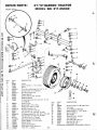
KEY
NO.
1
2
3
4
5
6
7
8
9
10
11
12
13
14
15
16
17
18
19
20
21
22
23
24
25
9
PART
NO .
5QOOP
1528P
1309H
634A521
3294P
634A277
9040H
7810H
2515R
7838R
6855M
1505P
4764H
634A278
8515R
558P
634A819
559P
8514R
634A813
1552P
6842M
7837R
634A98
2795R
E-Ring
Washer 13/ 16 x 1 · 1/4 x 14 Ga.
Bearing
Front Axle w/Bearings (Inc. Key No. 3)
Hex Bolt 5/8 · 11 x 5 Grade 5
Spindle Complete R.H.
Flanged Bearing
Gripco Locknut 3/8 · 24 UNF
Hardened Washer
Tie Rod and Joints (Inc. Key No's. 15, 16,
17, 18 & 19)
Grease Fitting
Washer 9/32 x 1/2 x 14 Ga.
Huglock Nut 5/8 x 11 UNC
Spindle Complete L.H.
Tie Rod Joint (R.H. Thread)
Hex Jam Nut 1/2 · 20 (R .H. Thread)
Tie Rod and Nuts (Inc. Key No's. 16 & 18)
Hex Jam Nut 1/2 · 20 (L.H . Thread)
Tie Rod Joint (L.H. Thread)
Steering Gear Sector and Arm
Washer 49/64 x 1 · 1/4 x 16 Ga.
Grease Fitting
Drag Link and Joints
Steering Bell Crank Weldment
Front Ti re · Tubeless
- 22 -
35
[ ] ) 36
KEY
NO.
26
27
28
29
30
31
32
33
34
35
36
PART
NO.
0856M
795R
2891 R
1562P
8798H
8785H
4831 H
8763H
3008P
3052P
515P
*STANDARD
DESCRIPTION
Grease Fitting 1/4 · 28 Taper Thrd.
Tire Valve
Front Wheel and Bearings
Washer 25/32 x 1 · 1/2 x 16 Ga.
*Roll Pin 5/32 x 1
Wear Washer
Elastic Nut 3/4 · 16 UN F
Dust Cap-Outer
Hex Bolt 5/16 · 18 x 1/2
" Hex Bolt 3/8 · 24 x 1
*Hex Nut 3/8-24
HARDWARE--PURCHASE LOCALLY
-
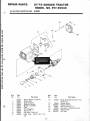
REPAIR PARTS:
ST/12-GARDEN TRACTOR
MODEL NO. 917.25930
another free manual from www.searstractormanuals.com
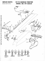
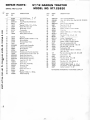
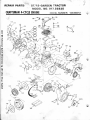
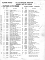
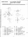
STARTER MOTOR NO. 33835
11
(
I
I
I
I
1
Ref.
No.
Part
No.
1
2
3
4
5
6
7
8
11
33835
33841
33842
33843
33854
33844
33433
33450
33845
33848
Part Name
Starter Motor, Complete
Cover, Dust
Ring, Retainer
Retainer, Spring
Spring, Anti-drift
Gear
Nut, Engaging
Nut, Lock
Cap Assy., Drive end
Card Assy ., Brush (Incl. No.
12)
. 23-
Ref.
No.
Part
No.
12
33849
13
14
15
16
17
18
33850
590500
33851
33852
650168
650723
Part Name
Brush & Spring Kit (Incl. 4 pes.
of No. 13)
Spring, Brush
Washer, Thrust
Bolt, 10-32 x 5-1/4
Cap Assy., Commutator end
Washer, Flat
Nut, Hex
REPAIR PARTS:__-.,.~'4~
ST/12-GARDEN TRACTOR
MODEL NO. 917. 25930
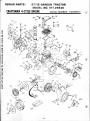
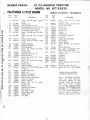
CRAFTSMAN 4-CYCLE ENGINE
another free manual from www.searstractormanuals.com
MODEL NUMBER: 143.662012
. 24.
'
1
'
REPAIR PARTS:
ST/12-GARDEN TRACTOR
MODEL NO. 917.25930
I
CRAFTSMAN 4-CYCLE ENGINE
Ref.
No.
1
another free manual from www.searstractormanuals.com
2
Part
No.
662012
33042
2A
4
5
5
27652
31950
31940
31941
6
6
31942
31943
7
8
9
9
650592
31944
31945
31946
10
11
20810
33390A
12
13
14
29783
31931
32238
14
32239
14
32240
14
32621
14
32622
15
15
15
15
15
16
17
32241
32242
32243
32625
32626
31919
33093A
18
19
20
21
32077
26073
28264
32150
-~
22
23
31939
32685
24
25
26
33893
33590
33984
27
28
29
*31956
32426
650588
MODEL NUMBER : 143.662012
Ref.
No.
Part Name
Complete Engine
Cylinder Assy. (Incl. Nos. 2A,
4 & 47)
Pin, Dowel
Seal, Oil
Valve, Intake (Standard)
Valve, Intake (1/32" oversize)
(Incl. No. 9)
Valve, Exhaust (Standard)
Valve, Exhaust (1/32" oversize) (Incl. No.9)
Key, Flywheel
Spring, Valve
Cap, Lower valve spring (Std:)
Cap, Lower valve spring (1/32"
oversize)
Pin, Valve spring retaining
Crankshaft Assy. (Incl. Nos.
12, 13, 78 & 79)
Pin, Crankshaft gear
Gear, Crankshaft
Piston & Pin Assy. (Incl. 2 of
No. 16) (Standard)
Piston & Pin Assy. (Incl. 2 of
No. 16) (.010 oversize)
Piston & Pin Assy. (Incl. 2 of
No. 16) (.020 oversize)
Piston & Pin Assy. (Incl. 2 of
No. 16) (.030 oversize)
Piston & Pin Assy ' (Incl. 2 of
No. 16) (.040 oversize)
Ring Set, Piston (Standard)
Ring Set, Piston (.010 oversize)
Ring Set, Piston ( .020 oversize)
Ring Set, Piston (.030 oversize)
Ring Set, Piston (.040 oversize)
Ring, Piston pin retaining
Rod Assy ., Connecting (Incl.
Nos. 18, 19 & 20)
Bolt, Connecting rod
Washer, Connecting rod
Nut, LockJ _S/16-24
__
Camshaft (Mech. Compression' ,
Release)
-Lifter, Valve
Cover, Cylinder (Incl. Nos. 4,
28, 34 & 43 )
Tube, Oil filler
"0" Ring
Dipstick Assy ., Oil (Incl. No.
25)
Gasket, Cylinder cover
Spacer, Governor rod
Screw, Hex hd. Sems, 1/4-20 x
Part
No.
34
35
36
37
29193
31963
650518
650544
38
39
40
7975
31965
30312
41
42
43
44
45
46
47
48
49
50
31967
31968
32425
31948
29193
31947
31930
*32246A
33034
650711
51
650714
53
54
55
56
33636
33035
6 50691
650781
57
58
27793
28942
59
650128
60
67
31976
30688
68
70
71
72
73
74
75
650690
28537
26460
30962
32579
610118
650561
76
77
78
79
81
650124
610750
31932
31928
*31971
82
*31 972
82A
32031
83
32577
Part Name
Ring, Retaining
Lever, Governor adjusting
Lockwasher, No. 10 E.T.
Screw, Fil. flex hd. self-locking,
10-24 X 7/ 8
Nut, Square, 10-24
Plate, Governor spring
Screw, Hex slotted washer hd.,
Sems, 10-32 x 1/2
Spring, Governor
Link, Governor
Rod Assy., Governor
Spool, Governor
Ring, Retaining
Gear Assy., Governor
Shaft, Mechanical governor
Gasket, Cylinder head
Head, Cylinder
Screw, Hex hd. cap, 5/16-18 x
1-5/8
Screw, Special hex hd. cap,
5/16-18 X 1-5/ 8
Plug, Spark
•'
Cover, Cylinder head
Washer, Flat
Screw, Hex hd. cap, Sems,
5/16-18 X 11/16
Clip, Conduit
Screw, Hex slotted hd. Sems,
1.0 -32 X 3/8
Screw, Fil. slotted hd. Sems,
10-24 X l/2
Extension, Bfower housing
Screw, Hex hd. cap, Sems,
1/4-20 X 1/2 , 1
Washer, Belleville
Washer, Flat
Clamp, Fuel line
Line, Fuel
Baffle, Blower housing
Cover, Spark plug
Screw, Phil. hex hd. Sems,
1/4-20 X 5/8
Nut, Hex 10-32
Grommet, Lead wire
Bearing, Tapered roller
Cup, Bearing
Gasket, Shim (.004/.005 thick,
see note 1)
Gasket, Shim (.005/.007 thick,
see note 1)
Spacer, Steel (.010 thick, see
note 1)
Cover, Cy~inder (See note 1)
2
32
30564
33
31964
Screw, Hex hd. cap Sems,
1/4-20 X 1
Clamp, Governor lever
*Indicates Parts Included in
Gasket Set, Ref. No. 169.
. 25.
)'
~
; '
REPAIR PARTS :
ST/12-GARDEN TRACTOR
MODE L NO. 917.25930
CRAFTSMAN 4-CYCLE ENGINE
another free manual from www.searstractormanuals.com
MODEL NUMBER : 143.662012
. 26 .
...
REPAIR PARTS:
ST/ 12-GARDEN TRACTOR
MODEL NO. 917.25930
CRAFTSMAN 4-CYCLE ENGINE
Ref.
No.
Part
No.
84
650512
Part Name
Screw, Hex hd. Sems, 5/16-18
7/8
Washer, Lock
Nut, Flywheel, 3/4-16
Housing, Blower (Incl. No. 73)
Decal, Name & Instruction
Lockwasher, Split, 5/16"
Screw, Hex hd. cap, 5/16-24 x
9/16
Screw, Hex hd. cap , 5/16-24 x
3/8
Screen, Starter pulley
Screw, Truss hd. mach., 1/4-20
X 3/4
Gasket, Breather
Breather Assembly
Tube, Breather
Screw, Fil. slotted hd. Sems,
10-24 X 1/2
Washer, Wave
Bushing, Governor lever
Lever, Control
Screw, Hex washer hd. , mach.,
10-24 X 5/8
Screw, Fil. slotted hd. mach.,
10-24 X 2
Washer, Flat
Spring, Locking
Screw, Fil. flex hd. self-locking,
1/4-20 X 1
Gasket, Carburetor
Baffle, Air
Gasket, Air cleaner
Bracket, Air cleaner
Bracket Assy ., Air cleaner
Cover, Air cleaner
Spacer, Cleaner
Screw, Phil. fil. hd. Sems,
10-32 X 5/8
Washer, Lock
Element, Air cleaner
Filter, Pre air
Nut, Wing, 1/4-20
Decal, Air cleaner
Washer, Flat
"0" Ring
MODEL N UM BER: 143.662012
Ref.
No.
Part
No .
130
650661
131
610906r
13'/
139
141
146
147
148
152
153
154
155
156
29774
32958
32959
26073
33038
33010
610901
32438
32154
32426
650713
157
162
32730
610902
163
650521
X
85
R6
another free manual from www.searstractormanuals.com
~~
90
91
92
650666
650594
33044A
30592
8274
650624
92A 650595
96
97
33776
650670
98
99
100
t01
*31 958
31957
27627
650128
102
103
104
105
28558
31966
31984A
650597
106
650591
107
108
110
30590A
33099
650451
111
112
115
116
117
119
121
122
*33861
34061
*27272
34071
32907A
32904
30767
650399
122A 27070
123
32008
124
32906
125
650513
126
32954
127
65067 5
128
32599
164
610908
164A 610904
t65 610903
165A 610905
167
33835
168
169
631878
33237A
Part Name
Screw, Phil. fil. hd. Sems,
1/4·20 X 3/4
Magneto, Solid state (Incl. 1\os.
74 , 76 , 77 & 164)
Line, Fuel
Fitting, Fuel
Pump, Fuel
Washer
Plug, Button
Fuel Pump Repair Kit
Flywheel
Nipple, Pipe (Oil drain)
Cap, Nipple
Spacer, Screen
Screw, Hex hd. cap, 5/ 16-18 x
5/ 8
Decal, Solid state
Coil Assy., Alternator (Incl.
Nos. 164A, 165 & 165A)
Screw, Phil. fil. hd. Sems,
10-32 X 1-1/8
Terminal
Terminal
Connector
Terminal
Motor, Starter (12 Volt) (Incl.
No. 56)
Carburetor (Incl. No. 111 )
Gasket Set (Incl. items marked
*)
*Indicates Parts Included in
Gasket Set, Ref. No. 169.
Note 1: Determine the gap between the cover and the
machined surface on the
cylinder, which can be from
.001" up to .007'', in which
case no shim gaskets will be
required. Use of gaskets must
be limited to a combined total
of a .010" thick. Steel spacers
must be used as required to
eliminate crankshaft end play.
. 27 .
r
REPAIR PARTS:
ST/12-GARDEN TRACTOR
MODEL NO. 917.25930
CARBURETOR NO. 631878
another free manual from www.searstractormanuals.com
_..
I
l
I
-7
15
··-@'-~
I
I
I
a
t:::J-16
5
I
I
11
I
I
I
I
I
I
:
I
I
21-@~
n
CJ)-25
23-
;~=aJ 22
I ®,
I
~ ~~ 12
I
~-13
!
/
~
/
I
v
Ref.
No.
Part
No.
1
631878
631879
2
3
4
5
5A
6
7
631777
631778
650506
630766
630738
650417
631880
8
9
10
11
630735
631881
*630748
*631027
I
I
I
Q l
/
31
Part Name
Ref.
No.
Part
No.
12
*631021
13
14
15
16
21
22
631022
631023
*631024
631700
631334
*631861
23
24
25
30
31
630740
*630898
*631028
630739
631862
Carburetor
Shaft & Lever Assembly,
Throttle
Spring, Throttle return
Shutter, Throttle
Screw, Rd. hd. 4-40 x 3/16
Spring, Idle regulating screw
Spring, Main adjustment screw
Screw, Idle regulating
Shaft & Lever Assembly,
Choke
Spring, Choke return
Shutter, Choke
Plug, Welch
Plug, Welch
. 28.
Part Name
Inlet Needle, Seat & Clip,
Assembly (Incl. No. 13)
Clip, Inlet needle
Float, Carburetor
Shaft, Float
Bowl, Float
Gasket, Bowl-to-body
Adjustment Screw Assembly,
Main (Incl. Nos. 5A, 21 , 23 &
30)
"0" Ring, Adjustment screw
Screw, Idle adjustment
Gasket, Bowl-to-body
Washer, Flat
Repair Kit (Incl. items marked
*)
t
..'
another free manual from www.searstractormanuals.com
r~
.
7880R· 5.4.76
ISears I
another free manual from www.searstractormanuals.com
MODEL NO.
917.25930
.
.
.
•
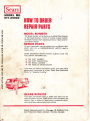
HOI TO ORDIR
RIPAIR PARTS
'
A'
MOD EL NUMBER
The Model Number will be found on the Model Plate attached
to the Chassis Channel, in front of the Seat. Always mention
the Model Number when requesting service or repair parts for
your Garden Tractor. •
REPAIR PARTS
All parts listed herein may be ordered from any SEARS, ROE BUCK AND CO. or SIMPSONS-SEARS LIMITED retail or
catalog store.
WH EN ORDERING REPAIR PARTS, ALWAYS G IVE THE
FOLLOWING INFORMATION:
e
THE PART NUMBER
e THE PART DESCRiPTION
e THE MODEL NUMBER
e
J
-
THE NAME OF MERCHANDISE
If the parts you need are not stocked locally, your order will be
electronically transmitted to a Sears Repair Parts Distribution
Center for "expedited handling".
SEARS SERVI CE
Your Sears merchandise takes on added val ue when you discover that Sears has over 2,000 Service Units throughout the
country. Each is staffed by Sears-trained, professional technicians using Sears approved parts and methods.
]
------------------------------------~v~
Sears. Roebuck and Co.. Chicago, Ill. 60684. U .S .A .
and Simpnons Sears Limited. Toronto. Canada
'~