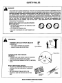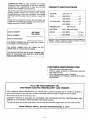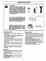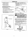
1
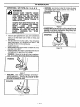
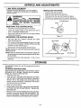
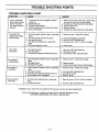
IMPORTANT MANUAL
Do Not Throw Away
SEA/R8
Operator's
Manual
Model No.
358.798010
(10")
358.798090
(13")
Always Wear Eye Protection
CUSTOMER
ASSISTANCE
1-800-235-5878
Mon.Sat. 7 a.m. - 7 p.m.
Sun.HOURS
10 a.m. (CST)
- 7 p.m.
I_
®
RRFTSMRN
I
ARNING
READ
THE
OPERATOR'S
MANUAL AND FOLLOWALL
WARNINGS AND SAFETY
INSTRUCTIONS.
FAILURE
TO DO SO CAN RESULT IN
SERIOUS INJURY.
Sears_ Roebuck
530-083295
02/06/95
4.0 AMP MOTOR
i-Automatic Head
IC WEEDWACKEW
•
•
•
•
Assembly
Operation
Customer Responsibilities
Service and Adjustments
and Co., Hoffman
Estates, IL 60179 USA
SAFE'rY RULES
I_
WARNING
- WHEN USING ELECTRIC GARDENING APPLIANCES,
BASIC SAFETY PRECAUTIONS
SHOULD ALWAYS BE FOLLOWED TO REDUCE THE RISK OF FIRE, ELECTRIC SHOCK, AND PERSONAL INJURY. READ ALL INSTRUCTIONS.
1
I
OPERATOR SAFETY
•
To reduce the risk of electrical shock this equipment has a
polarized plug. This plug will fit in a polarized outlet or exten•
Dress properly. Always wear safety glasses or similar eye
sion cord only one way. (one blade is wider than the other). If
protection when operating, servicing, or performing maintethe plug does not fitfully in the outlet, reverse the p lug. If it sti!l
nance on your unit. (Safetyglasses areavailable.) Always wear
does not fit, contact aqualified electrician to insta!lthe proper
face mask or dust mask if operation is dusty. Always wear
outlet. Do not change the plug in any way.
heavy, long pants, long sleeves, boots, and gloves. Do notgo
UNIT SAFETY
barefoot or wear sandals, short pants, or short sleeves.
•
Inspect entire unit before each use. Replace damaged parts.
• Secure hair above shoulder length. Secure or remove loose
Make sure all handles, guards, and fasteners are in place and
clothing and jewelry or clothing with loosely hanging ties,
securely fastened. A guard or other part that is damaged
straps, tassels, etc. They can be caught in moving parts.
should be properly repaired or replaced by your Sears Service
•
Being fully covered helps to protect you from pieces of toxic
Center.
plants thrown by spinning line.
• Replace trimmer head parts that are cracked, chipped, or
• STAYALERT- -Do not operate this unit when you are tired, ill,
damaged before using the unit.
or under the influence of alcohol, drugs, 0r medication. Watch
•
•
"
'
Use only .065 Ii diameter
genuine
tr i mmer I=ne.
what you are doing; use common sense.
(See "Accessories") Never use wire, rope, string etc.
AVOID UNINTENTIONAL STARTING OF THE UNIT-• Use only the specified trimmer head. Make sure the semiNever carry the unit with your finger on the switch. Be sure the
automatic head is properly installed and securely fastened.
switch is in the off position before connecting the extension
Disconnect unit from the power supply before changing
cord.
semi-automatic
head.
Restrict the use of this unit to persons who read, understand,
•
Use only recommended accessories as recommended. Use
and fo!lowthe warnings and instructions in this manual and on
of any other accessory may increase the risk of injury.
the unit.
CUTTING SAFETY
ELECTRICAL
SAFETY
•
Inspect the area to be cut before each use. Remove objects
•
Use only a 120 A.C. voltage supply as shown on the name
(rooks, broken glass, nails, wire, string, etc.) which can be
plate of the unit.
thrown or become entangled in the semi-automatic
head.
• Avoid dangerous situations. Do not use in the presence of
° KEEP CHILDREN AWAY- -Keep others including children,
flammable liquids or gasesto avoid creating afire or explosion
animals, bystanders and helpers outside the 100 foot (30 meand/or causing damage to unit.
ter) Hazard Zone. Stop the unit immediately if you are ap•
WARNING--TO
REDUCE THE RISK OF ELECTRICAL
proached. Never allow children to operate the unit.
SHOCK--Do
not use in damp or wet locations or around
• Stop the unit and disconnect the power source when not in
swimming pools, hottubs, etc. Do notexpose to snow, rain, or
use.
water to avoid the possibility of electrical shock.
• DO NOT OVERREACH OR STAND ON UNSTABLE SUP• WARNING--Toreducetheriskofelectricalshock,
useextenPC RT- - Keep firm footing and balance. Do not over- reach,
sion cords specifically marked as suitable for outdoor
• Keep the semi-automatic
head below waist level.
appliances having electrica! rating not less than the rating of
• Do not raise handles above your waist, The semi-automatic
the unit. The cord must be marked with the suffix "W-A" (in
head can come dangerously close to your body,
Canada "W"). Use a polarized cord. Make sure your extension
• Keep all parts of your body away from semi-automatic
head
cord is in good condition. Replace damaged cords. An underwhen unit is running.
sized extension cord will cause a drop in line voltage resulting
• USE UNIT PROPERLY--Use
only for jobs explained in this
in toss of power and overheating. If in doubt, use the next
manual. Do not force the unit, it will do the job better and with
heavier gauge. The smallerthe gauge number, the heavier the
less likelihood of a risk of injury at the rate for which it was decord. (NOTE: Figure 1 shows the correct size to be used designed.
pending on the cord length).
• Use only in daylight or in good artificial light,
•
DO NOTATTEMPTTO REPAIR UNIT--Inspectthe
insulation MAINTENANCE
SAFETY
and connectors on the unit and extension cord before each
•
Maintain unit according to recommended procedures. Keep
use. If there is any damage, do not use until damage is rethe cutting line at the proper length.
paired by your Sears Service Center/Dept.
•
Have all internalservice and maintenance not explained inthis
•
DO NOT ABUSE CORD. Never carry the unit by the extension
manual performed by your Sears Service CentedDept.
to
cord or yank the extension cord to disconnect the unit.
avoid creating a hazard and/or voiding your warranty. When
• To reduce the possibility of the extension cord disconnecting
servicing use only identical replacment parts.
from the unit dudng operation, slip the extension cord behind
o DISCONNECT UNIT FROM THE POWER SUPPLY before perthe tab on the cord retainer as shown in Figure 2. Plug extenforming maintenance.
sion cord into the recessed plug on the handle ofthe unit. Fig. Never douse or squirt the unit with water or any other liquid.
ure 2.
Clean unit and labels with a damp sponge. See "Storage."
•
Do not use the unit if the switch does nottum the unit on and off
Keep handles dry, clean, and free from oil and grease.
properly. Repairs to the switch must be made by your Sears
•
Keeptheairventscleanandfreeofdebristoavoidoverheating
Service Center/Dept,
the motor. Clean after each use. See "Specifications'' for loca, Keep the extension cord clear of operator and obstacles at all
tions.
times, Do not expose .cords to heat, oi! ,.water, or sharp edges.
TRANSPORTING
AND STORAGE
•
Avoid any body contact with any grounded conductor, such
• Hand carry the unit with the motor stopped,
as metal pipes or wire fences, to avoid the possibility of elec• Allow the unit to cool and secure the unit before storing or
tric shock.
transporting in a vehicle.
•
Ground Fault Circuit Interrupter (GFCI) protection should be
•
Store the unit so the line limiter cannot accidentally cause
provided on the circuit or outlet to be used for this unit. Reinjury.
ceptacles are available having built-in GFCI protection and
•
STORE UNIT INDOORS--Store
unit unplugged in a high,
may be used for this measure of safety.
dry place out of the reach of children.
|
LOOK FOR THIS SYMBOL
IT MEANS
- ATTENTION!!!
TO POINT
BECOME
-2-
OUT IMPORTANT
SAFETY PRECAUTIONS.
ALERT!!! YOUR SAFETY IS INVOLVED,
I
I
SAFETY RULES
_
DANGER
THIS POWER UNIT CAN BE DANGEROUS! THIS UNIT CAN CAUSE SERIOUS INJURY OR BLINDNESS TO THE
OPERATOR AND OTHERS, WHEN USING AN ELECTRIC TRIMMER, THESE BASIC SAFETY PRECAUTIONS
MUST BE FOLLOWED TO REDUCE THE RISK OF INJURY, FIRE, AND ELECTRIC SHOCK. FAILURE TO FOLLOW
ALL INSTRUCTIONS CAN RESULT IN BLINDNESS OR OTHER SERIOUS INJURY. THE OPERATOR IS
RESPONSIBLE FOR FOLLOWING THE WARNINGS AND INSTRUCTIONS IN THIS MANUAL AND ON THE UNIT.
READ THE ENTIRE OPERATOR'S MANUAL BEFORE ASSEMBLING AND USING THIS UNIT! RESTRICT THE
USE OF THIS UNIT TO PERSONS WHO READ, UNDERSTAND, AND
FOLLOW THE WARNINGS AND
INSTRUCTIONS
IN THIS MANUAL AND ON THE UNIT.
(SEE ADDITIONAL SAFETY INSTRUCTIONS
THROUGHOUT THIS MANUAL)
NEVER USE BLADES OR FLAILING DEVICES
WITH THIS UNIT.
-
THE BLADE CAN COME OFF AND SERIOUSLY HURT
YOU AND OTHERS.
-
STAY CLEAR OF SPINNING LINE.
-
THIS UNIT IS DESIGNED FOR LINE TRIMMER USE
ONLY
QQQ
WARNING
TRIMMER
Thrown_
LINE
CAN
THROW
!
OBJECTS
VIOLENTLY.
- YOU CAN BE BLINDED OR INJURED.
-
Eye Protection
WEAR EYE AND LEG PROTECTION.
Hazard Zone
HAZARD ZONE
OBJECTS
FOR THROWN
-
TRIMMER
LINE CAN THROW OBJECTS VIOLENTLY.
-
OTHERS CAN BE BLINDED OR INJURED.
-
KEEP PEOPLE AND ANIMALS 50 FEET (15 METERS)
AWAY.
READ OPERATOR'S
MANUAL.
-
FOLLOW ALL WARNINGS
-
FAILURE TO DO SO CAN RESULT IN SERIOUS
INJURY.
-
BE THOROUGHLY
CONTROLS
UNIT.
AND INSTRUCTIONS.
FAMILIAR WITH THE
AND THE PROPER USE OF THIS
Operator's
Manual
SAVE THESE INSTRUCTIONS
3
Safety
Labels
CONGRATULATIONS
on your purchaseof a Sears
CraftsmanElectricWeedwacker.
It hasbeendesigned,
engineeredand manufactured
to give you the best
possibledependability
andperformance.
Shouldyouexperience
anyproblemsyoucannoteasily
remedy,pleasecontactyour nearestSears Service
Center/Department.
Searshascompetent,welltrained
techniciansandthe propertoolstoserviceor repairthis
unit.
Pleasereadandretainthis manual.Theinstructions
will
enableyouto assemble
andmaintainyourunitproperly.
Alwaysobservethe"SAFETY
RULES."
PRODUCT
SPECIFICATIONS
VOLTAGE: .......
120 Volts A.C.
AMPS ...........
358.798010
.......
_
358.798090
.......
",-','J4r.
0
CUTTING PATH .. 358.798010
.........
t0"
358.798090
.........
13"
TRIMMER LINE: ........
MODELNUMBER;
SERIALNUMBER:
358.798010
358.798090
3.7
065" Dia. line
LINE FEED ......
Semi-Automatic
Head
WEIGHT
358.798010
....
: ....
358.798090
.........
........
4,0 Lbs.
4.5 Lbs.
DATE OF PURCHASE:
PATENTS: 4,035,912; 4,052,789; 4,183,138; 4,189,833; 4,161,820; I
t MANUFACTURED
4,167,812; 4,211,004;
UNDER
4.362,074;
ONE OR
4,904,827.
MORE OF THE FOLLOWING U.S.| t
THE SERIAL NUMBER WILL BE FOUND
UPPER PART OF THE MOTOR HOUSING.
J
i
THE MODEL NUMBER WILL BE FOUND ON A DECAL
ATTACHED TO THE PRODUCT.
ON THE
YOU SHOULD RECORD BOTH SERIAL NUMBER AND
DATE OF PURCHASE AND KEEP IN A SAFE PLACE
FOR FUTURE REFERENCE.
CUSTOMER
•
•
•
CRAFTSMAN
RESPONSIBILITIES
Read and observe the safety rules.
Follow a regular schedule in maintaining, caring for,
and using your unit.
Follow the instructions under "Customer
Responsibilities" and "Storage" sections of this Operator's Manual.
FULL ONE YEAR WARRANTY ON
ELECTRIC WEEDWACKER
® LINE TRIMMER
If this Craftsman Electric Weedwacker® Line Trimmer fails to perform properly due to a defect in material or
workmanship within (!) one year from the date of purchase, Sears will repair or replace it, free of charge.
This warranty does not cover the nylon line.
WARRANTY SERVICE IS AVAILABLE BY RETURNING THE CRAFTSMAN
TRIMMER TO THE NEAREST SEARS STORE IN THE UNITED STATES.
ELECTRIC WEEDWACKER®
LINE
This warranty gives you specific legal rights, and you may also have other rights which vary from state to state.
SEARS, ROEBUCK AND CO., D!817WA, HOFFMAN
ESTATES, IL 60179
TABLE OF CONTENTS
Safety Rules ...................................
Product Specifications ..........................
Warranty .....................................
Accessories ...................................
Assembly .....................................
Operation .....................................
2
4
4
5
6
7
Customer Responsibilities ......................
Service and Adjustments .......................
Storage .....................................
11
12
: 12
Trouble Shooting ..............................
Repair Parts Ordering/Service
.........
II
I
13
Back Cover
I
INDEX
II II
A
Accessories ...................................
Assembly .....................................
C
Customer Assistance Hotline ..........
Customer Responsibirities ......................
H
Hardware Contents .............................
K
Know Your Weedwacker ........................
L
Line Advancement
.............................
Line Limiter ....................................
Line Replacement .............................
III
M
Maintenance Schedule ......................
Mode! Number ..............................
O
Operation ............................
Ordering Repair Parts ................
S
Safety Rules ................................
Specifications ...............................
Storage ....................................
T
Trouble Shooting ............................
W
Warranty ....................................
5
6
Back Cover
11
6
7
9
9
12
III
11
4
7, 8, 9, I0
Back Cover
2,3
4
12
13
4
ACCESSORIES
II
IIIIIIIIIIIIII
I I IIIII
I III
I I II IIIIII
IIIII
IIIII
These accessories and attachments were avai!ab!e when the unit was purchased originally.
most Sears retai! outlets and service centers.
They are als0 available at
Most Sears stores can order these items for you when you provide the
model number of your unit.
ACCESSORIES
Safety Goggles
Spool with line
(.065" diameter only)
Bulk Line
(.065" diameter only)
I
HARDWARE CONTENTS
LOOSE PARTS IN CARTON NOT SHOWN ACTUAL SiZE
REMOVE WEEDWACKER FROM
CARTON.
•
•
•
Remove loose parts included with Weedwacker.
Remove all packing material.
Check carton thoroughly for additional
loose parts.
TOOLS REQUIRED
•
O3erator's
Manual
None
(1)
ASSEMBLY
i
NOTE: Do not remove the tape secured to the line limiter.
The tape will quickly wear off during trimmer use.
EXTENSION
CORD ATTACHMENT
(Fig. 1 & 2)
•
Use only a 120 A.C. voltage supply as shown on the
nameplate of the unit to power your unit.
•
The extension cord used to reach the power source
must be:
MINIMUM
WIRE GAUGE
RECOMMENDATIONS
VOLTS
120
J 25-50FT.
16
A.W.G.*
*American Wire Gauge
A polarized Extension Cord. (One blade is wider
than the other.)
• ' Specifically marked as suitable for outdoor use.
The cord must be marked with the suffix "W-A."(in
Canada "W").
• Heavy enough to carry the current from the power
source the full length of the extension cord to the
unit. Otherwise, loss of power and overheating can
occur causing damage to the unit. Refer to Figure
1 for minimum wire gauge recommendations,
The
cord must be marked with the proper wire gauge.
° In good condition. Cord insulation must be intact
with no cracks or deterioration.
Plug connectors
must be undamaged.
• Extension cords are available for this unit.
t
50,100FT.
16
A.W.G.*
J 100-150FT.
14
A.W.G.*
Figure 1
•
•
Secure the cord by connecting
trated in figure 2.
the the unit as illus-
•
Insert the cord socket into the recessed plug on the
unit..
To reduce the risk of electric shock, this unit has a
polarized plug (one blade is wider than the other). This
plug will fit in a polarized extension cord on!y one way. If
the plug does not fit fully into the extension cord; reverse
the cord. If it still does not fit, make sure you have a
polarized extension cord. If the extension cord does not
fit into the outlet, reverse the cord. If it stiltdoes not fit into
the outlet, contact a qualified electrician to install the
proper outlet. Do not change the plug or socket of the
unit or extension cord in any way.
Figure 2
CHECK
LIST
•
Check all fasteners. Make sure they are tight and
there are no loose parts.
•
Check the position of the assist handle and trigger
handle for operating comfort.
Make sure your extension
suffix of "W-A". (In Canada
cord is marked with a
"W").
Make sure the semi-automatic head is properly assembled and securely fastened.
OPERATION
KNOW YOUR
WEEDWACKER
(Fig. 3)
READ THIS OPERATOR'S MANUAL AND SAFETY RULES BEFORE OPERATING YOUR WEEDWACKER ®. Compare the
illustrations with your unit to familiarize yourself with the location of the various controls and adjustments. Save this
manual for future reference.
RECESSED j'_'_'_-
_
_t.=_ _
TRIGGER HANDLE
oo.o.FA,NER"
TR,GG
,ST.AND E
\
A,.VENTS
\\ \
MOTOR
HOUS,NG
tl/1
SEMI-AUTOMATIC HEAD
(Underside of Debris Shield)
"_"_-_"-CUTTING LINE
Figure 3.
The LINE LIMtTER cuts the cutting line to the proper cutThe RECESSED PLUG is where you attach your extension cord to the unit.
ing length.
The ASSIST HANDLE is used to help hold and guide the
unit.
The TRIGGER SWITCH
is used to turn on the unit.
Squeeze the trigger switch to operate the unit.
DOUBLE
INSULATION
The SEMI-AUTOMATIC
HEAD holds the cutting fine and
rotates during operation.
CONSTRUCTION
This unit is Double Insulated to help protect against
electric shock. Double insulation construction consists
of two separate "layers" of electrica! insulation instead of
grounding.
ALL
ELECTRICAL REPAIRS TO THIS UNIT,
WARNING
INCLUDING HOUSING, SWITCH, MOTOR,
REPAIRED
BY QUALIFIED
SERVICE
PERSONNEL.
REPLACEMENT
PARTS
FOR A DOUBLE INSULATED APPLIANCE
MUST BE IDENTICAL TO THE PARTS
THEY REPLACE. A DOUBLE INSULATED
APPLIANCE
IS MARKED
WITH THE
:WORDS
"DOUBLE
INSULATION,
OR
',DOUBLE
INSULATED." THE _YMBOL
(SQUARE WITHIN A SQUARE) 9
MAY
ALSO
MARKED
THE APPLIANCE.
ETC., BEMUST
BE ON
DIAGNOSED
AND
FAILURE TO HAVE THE UNIT REPAIRED
BY
SEARS
QUALIFIED
SERVICE
PERSONNEL CAN CAUSE THE DOUBLE
INSULATION
CONSTRUCTION
TO
BECOME INEFFECTIVE AND RESULT IN
SERIQ_S INJURY.
Tools and appliances built with a double insulation system are not intended to be grounded.
No grounding
means is provided on this unit, nor should a means of
grounding be added to this unit. As a result, the extent
sion cord used with your unit can be plugged into any
standard 120 volt electrical outlet.
Safety precautions must be obsewed when operating
any electrical tool. The double insulation system only
provides added protection against injury resulting from
an internal electrical insulation failure.
?
•
,,=l i i L
OPERATION SAFETY
&
WARNING
THE RAPIDLY MOVING LINE CAUSES OBJECTS TO BE THROWN VIOLENTLY. THE
SHIELD WILL NOT PROVIDE COMPLETE
PROTECTION TO THE OPERATOR OR OTHERS. THE OPERATOR MUST WEAR A SAFETY FACE SHIELD OR GOGGLES. STAY
CLEAR OF SPINNING LINE. ALWAYS WEAR
HEAVY, LONG PANTS AND SHOES OR
BOOTS. KEEP OTHERS AT LEAST 50 FEET
(15 METERS) AWAY.
I
Thrown
t
Eye
Protection
THIS UNIT WILL THROW OBJECTS AND
CUT.
KEEP OTHERS INCLUDING CHILDREN, ANIMALS, BYSTANDERS, AND HELPERS AT LEAST 50 FEET (15 METERS) AWAY
FROM THE OPERATOR AND UNIT. STOP
THE UNIT IF YOU ARE APPROACHED.
CUTTING LINE HEAD PARTS THAT ARE
CHIPPED, CRACKED, BROKEN, OR DAMAGED IN ANY OTHER WAY CAN FLY APART
AND CAUSE SERIOUS INJURY. DO NOT
USE. REPLACE DAMAGED PARTS BEFORE
USING THE UNIT.
OPERATOR
•
SAFETY
CUTTING
Always wear a face safety shield or goggles. See
'_ccessories."
•
•
Always wear heavy, long pants, long sleeves,
shoes or boots, and gloves. See '_,ccessories." Do
not go barefoot or wear sandals.
Stay clear of spinning line.
•
Being fully covered wi!l help protect you from pieces of
toxic plants such as poison ivy thrown by the trimmer
head which could be more of a hazard than touching
the plant itself.
• Secure hair above shoulder length. Secure or remove
loose clothing or clothing with loosely hanging ties,
straps, tassels, etc. They can be caught in moving
parts.
• Do not operate this unit when you are tired, ill, or
under
the influence
of alcohol,
drugs, or
medication.
•
•
•
•
•
•
UNIT SAFETY
•
•
•
•
Use Only Genuine
Replacement Parts
Inspect the entire unit before each use. Replace
damaged parts. Make sure all fasteners are in place
and securely fastened.
Use only .065" diameter line, Never use wire, rope,
string, etc.
Make sure the trimmer head is properly assembled
and securely fastened.
Use only genuine accessories or attachments as
recommended.
--
8
-
SAFETY
Inspect area to be cut before each use. Remove objects (rocks, broken glass, nails, wire, string, etc.)
which can be thrown or become entangled in the trimmer head. Always cut to the left side of the unit so thai
clippings and debris will be thrown away from you.
Hold the unit firmly.
Keep firm footing and balance. Do not over-reach.
Keep the trimmer head below waist level.
Do not raise the unit above your waist. The trimmer
head can come dangerously close to your body.
Keep all parts of your body away from the trimmer
line when the unit is running.
Use only for jobs explained in this manual.
OPERATION
STOPPING
YOUR UNIT
• Release the trigger switch.
STARTING
•
YOUR
ASSIST
•
•
•
UNIT
Squeeze the trigger switch.
OPERATING
POSITION
HANDLE
ADJUSTMENT
(Fig. 5)
Remove finger from trigger switch to turn off trimmer.
Loosen wing nut.
Slide assist handle up & down tube with left hand to a
comfortable operating position.
Tighten wing nut.
•
(Fig. 4)
Before operating the unit, stand in the operating position
and check for the following:
• Operator wearing eye protection.
•
Operator wearing heavy clothing.
•
Right arm slightly bent, hand holding trigger handle.
•
Left arm straight, hand holding assist handle.
•
Unit below waist level
•
Without operator bending over, the semi-automatic
head is near and parallel to the ground and easily con- .
tacts the material to be cut.
Trigger Switch
Tube
Wing Nut _
P/
Figure 5.
TRIMMER
_IL
OPERATING POSITION
LINE
ADVANCE
(Fig. 6)
MATIC
HEAD
AN ABRASIVE
SURFACE
CAUTION:
DOONNOT
BUMP SEMI-AUTOSUCH AS CONCRETE,
ASPHALT, OR
GRAVEL TO ADVANCE THE LINE.
BUMPING THE SEMI-AUTOMATIC
HEAD
ON AN ABRASIVE SURFACE CAN CAUSE
EXCESSIVE WEAR OR DAMAGE THE UNIT,
Your trimmer is equipped with a semi-automatic
head.
Whenever
the tap button is pressed,
the head
automatically advances a predetermined amount of line.
°
While the semi-automatic
head is turning, hold it parallel to and above a grassy area of ground.
Tap semi-automatic
head lightly on the ground one
time. Approximately 1-1/2 to 3 inches of line will be
advanced after each tap. Figure 6.
The line limiter on the plastic shield will cut line to the
correct length. The most efficient line length is maximum
length allowed by line limiter.
TAP
!
Figure 4.
Tap Button
Figure 6.
--9--
OPERATION
OPERATING
/ USE T!PS
•
MOWING Your trimmer is ideal for mowing in places
conventional lawn mowers cannot reach. Keep the
........
line parallel to the ground.
(Fi 9. 7, 8, 9, & 10)
WARNING
DO NOT CROWD LINE WHEN CUTTING
AROUND
HARD OBJECTS
(ROCKS,
GRAVEL, FENCE POSTS, ETC), WHICH
CAN DAMAGE THE SEMI-AUTOMATIC
HEAD, BECOME ENTANGLED IN THE
LINE, OR BE THROWN CAUSING A
SERIOUS HAZARD.
ALWAYS WEAR EYE PROTECTION. THIS
UNIT IS NOT DESIGNED FOR EDGING.
NEVER
LEAN
OVER
THE
SEMI-AUTOMATIC
HEAD. ROCKS OR
DEBRIS
CAN
RICOCHET
OR
BE
THROWN INTO EYES AND FACE AND
CAUSE
BLINDNESS
OR
OTHER
SERIOUS INJURY.
The line will easily remove grass and weeds from
around walls, fences, trees, and flower beds, but it
also can cut the tender bark of trees or shrubs and
soar fences.
The tip of the line does the cutting. You will achieve
best performance and minimum line wear by not
crowding the line into the cutting area.
Allow the unit to reach full speed before entering the
material to be cut.
Always release the trigger switch and allow the unit to
stop when not cutting.
Hold the bottom of the semi-automatic
head about 3
inches above the ground and at an angle,
TRIMMING
Allow only the tip of the line to make contact. Do not force the trimmer line into the work area
TRIMMING
__,,
...
Go'_m O"
O
_' V
Figure 7.
SCALPING
The scalping technique removes unwanted vegetation. Allow the tip of the line to strike
the ground around trees, posts, monuments, etc. This
technique increases line wear.
SCALPING
Figure 8.
MOWING
•
Figure 9.
SWEEPING The fanning action of the rotating line can
be used for a quick and easy clean up. Keep the line
parallel to and above the surfaces being swept and
move the unit from side to side.
SWEEPING
Figure10.
CUSTOMER
MAINTENANCE
RESPONSIBILITIES
SCHEDULE
Fill in dates as you complete regular service.
Before
Use
Check for damaged or worn parts.
X
Check for loose fasteners and parts.
X
Clean unit and labets
GENERAL
After
Use
Service Dates
X
BEFORE EACH USE
RECOMMENDATIONS
The warranty on this unit does not cover items that have
been subjected to operator abuse or negligence. To
receive full value from thewarranty, the operator must
maintain unit as instructed in this manual.
CHECK FOR DAMAGED/WORN
•
CHECK
FOR LOOSE
Some adjustments will need to be made periodically to
properly maintain your unit.
•
•
All adjustments in the "Service and Adjustments" section
of this manual should be checked at least once each
season.
AFTER EACH USE
Follow the maintenance schedule in this manual.
&
WARNING
•
•
HAVE CUTTING LINE HEAD PARTS THAT
ARE
CRACKED,
DAMAGED
IN
ANY
CHIPPED,
OR
OTHER
WAY
REPLACED BEFORE USING THE UNIT,
- !1 -
FASTENERS/PARTS
Semi-Automatic
Head
Assist Handle Wing Nut
CLEAN
•
PARTS
Semi-Automatic
Head - replace semi-automatic
head parts that are bent warped, cracked, or damaged in any way.
UNIT AND LABELS
Clean the unit using a damp cloth with a mitd detergent.
Wipe off the unit with a clean dry cloth.
Keep air vents free of debris at all times.
SERVICE AND ADJUSTMENTS
LINE REPLACEMENT
INSTALLING
Cuting line may be replaced by one of two different
methods: rewinding the existing spool or installing a
prewound spool.
ALWAYS
USE
RECOMMENDED J
REPLACEMENT LINE. DO NOT USE WIRE_
OR METAL REINFORCED LINE - BROKEN
WARNING
PIECES
CAN
BECOME
DANGEROUSf I
MISSILES.
REMOVING
THE EXISTING
Pull firmly on the tap button/spool to remove.
Check the indexing teeth on the spool and hub for
wear. If necessary, replace spool.
•
Use a clean cloth to wipe the inner and outer surfaces
of the hub and spool.
•
•
THE EXISTING
Use only .065 inch (1.65mm)
sizes will damage unit.
insert line into hub as shown.
•
•
•
Align the notch with the line exit hole.
Push spool into the hub until it snaps into place.
Pull the line to release it from the notch in the spool.
Tap Button/Spool
Hole--._.___
Figure 11.
SPOOL
diameter line. Other
Line in Notch
\,,
Cut a length of line approximatelY18 feet,(5 m). Insert
one end of the line about 1/2 inbh-_t0" mm) into the
small hole on the inside of spoof.
• Wind the line evenly and tightly onto the spool.
_iOTE: Winding too much line will cause head to jam aor
feed improperly.
NOTE: Failure to wind the line in the direction indicated or
using excessive line will cause the bump head to operate incorrectly.
•
•
SPOOL
•
•
REWINDING
Push the line into the notch leaving 3"-5"
unwound.
Hub
Do not wind past this line on spool.
(8-12 cm)
STORAGE
Immediately prepare your unit for storage at the end of
the season.
STORAGE
INSTRUCTIONS
If your trimmer is to be stored for a period of time, clean it
thoroughly prio_: to storage. Remove any dirt, sawdust,
leaves, etc. Store in a clean dry area.
• Clean the entire unit.
°
•
•
•
THE SPOOL
Open the semi-automatic
head assembly and clean
any dirt, grass or debris that has collected. Inspect the
trimmer line, if old (chalky look and sticky to the
touch), remove and discard. Instalf fresh new line the
next time product is to be used.
Clean air vents of debris.
Reassemble all loose parts, being sure that a!l handles
are in place and are securely fastened. Replace any
damaged parts.
Store your unit in a well ventilated area and covered, if
possible, to prevent dust and dirt accumulation.
Do
not cover with plastic. Plastic cannot breathe and will
induce condensation and eventual rust or corrosion.
- !2 -
Figure 11.
Line exit hole
TROUBLE SHOOTING POINTS
TROUBLE
SHOOTING
SYMPTOM
CHART
CAUSE
Semi-automatic
head stops under a
load or does not
turn when switch is
pressed.
REMEDY
1. Crowding trimmer line against material
being cut.
2. Electrical failure.
3. Thrown circuit breaker.
4. Debris wrapped at semi-automatic head.
5 None ofthe above.
t.
2.
3,
4.
5.
,
Line does not
advance or breaks
while cutting.
Back trimmer head
cut; allow tip of line
Contact your Sears
Check breaker box.
Remove debris.
Contact your Sears
away from grass being
to do the cutting.
Service Center/Dept.
Service Center/Dept.
,,,,,
1. Line improperly routed in semi-automatic
head.
2. Line improperly wound onto spool.
3. Line size incorrect.
4. Too little line outside semi-automatic
head.
.
Dirt accumulated on cover.
5. Clean cover.
1. Line size incorrect.
2, incorrect spoof.
3. Crowding line against material being cut.
1. Use only .065" diameter line.
2. Use proper spool.
3. Cut with tip of line, fully extended.
Line releases
continuously.
Line improperly routed in semi-automatic
head.
2,
Damaged spool.
3. Damaged drive gear.
1. Remove cover. Check line routing.
Line usage is
excessive.
1. Line improperly routed in semi-automatic
head.
.
Line size incorrect.
3. Crowding line against material being cut.
4. Spool teeth worn or damaged.
Line welds
onto spool.
,
Line pulls back
into head.
.
Too little line outside of semi-automatic
head.
Line size incorrect.
1. Remove cover, Check line routing.
2. Rewind line tightly and evenly.
3. Use only .065" diameter line.
4. Remove cover. Pul! 4" of line to outside.
2. Replace spool
3. Contact your Sears Service Center/Dept.
1. Remove cover. Check line routing.
2. Use only .065" diameter line.
3. Cut with tip of line.
4. Replace spool.
1. Remove cover. Pull 4" of line to outside.
2; Use only .065" diameter line.
If situations occur which are not covered in this manual, use care and good judgement.
ff you need assistance, contact your Sears Service Center/Departmdnt
CUSTOMER ASSISTANCE HOTLINE at 1-800-235-5878.
- 13 -
or the
S_E S
Operator's
Manual
Model No.
358.798010
358.798090
(10")
(13")
IF YOU NEED REPAIR
SERVICE OR PARTS:
REPAIR SERVICE
1-800-4-REPAIR
(1-800-473-7247)
ORDERING PARTS
1-800-FON-PART
1-800-366-7278
CUSTOMER
ASSISTANCE
1-800-235-5878
CRRFTSMgNo
3.0/3.3 AMP MOTOR
10"/13" Semi-Automatic Head
ELECTRIC WEEDWACKER _
Each Electric Weedwacker ® has itsown model number, The model
number for your unit will be found on a decal attached to the unit.
All parts listed herein may be ordered through Sears, Roebuck and
Co. Service Centers and most Retail Stores.
WHEN ORDERING REPAIR PARTS, ALWAYS GIVE THE FOLLOWING INFORMATION
• PRODUCT - "ELECTRIC WEEDWACKER"
• MODEL NUMBER-
358.798010
/ 358.798090
• PART NUMBER
" PART DESCRIPTION
Your Sears merchandise has added value when you consider that
Sears has service units nationwide staffed with Sears trained technicians.., professional technicians specifically trained on Sears products, having the parts, tools and the equipment to insure that we
meet our pledge to you, we service what we sell.
If you need assistance, contact your SEARS Service Center/Department or the CUSTOMER ASSISTANCE HOTLINE t-800-235-5878
Mort, - Sat, 7 a,m. - 7 p.m.
Sun, HOURS
10 a.rn, (CST)
- 7 p.m.
Sears, Roebuck
and Co., Hoffman
Estates, tL 60179 USA
PRINTED
IN U.S.A,