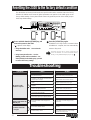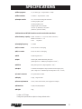
1
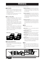
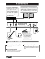
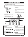
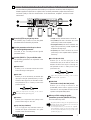
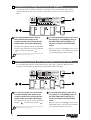
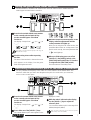
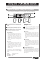
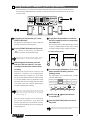
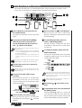
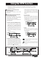
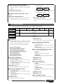
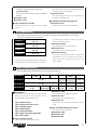
ADVANCED GUITAR EFFECTS PROCESSOR
OPERATION MANUAL
CONTENTS
Introduction
Glossary
Names and Functions
••••••••••••••••••••••••••••••••••••••••••••••••••••••••••••••••••••••••••••••••••••••••••
Front panel
Rear panel
Connections
••••••••••••••••••••••••••••••••••••••••••••••••••••••••••••••••••••
1
2
••••••••••••••••••••••••••••••••••••••••••••••••••••••••••••••••••••••••••••••
2
2
••••••••••••••••••••••••••••••••••••••••••••••••••••••••••••••••••••••••••••••••••••
3
•••••••••••••••••••••••••••••••••••••••••••••••••••••••••••••••••••••••••••••
Preparing for performance
Listening to a patch
••••••••••••••••••••••••••••••••••••••••••••••••••••••••
3
•••••••••••••••••••••••••••••••••••••••••••••••••••••••••••••••••••••••
4
Panel display in Play mode
Selecting a patch
Adjusting the volume level and tonal quality according to the
acoustic environment
Temporarily turning the effects off (Bypass)
Temporarily muting the sound output from the 2100
Tuning the guitar (Auto Tuner function)
Fine-tuning the reference pitch of the tuner (Calibration)
•••••••••••••••••••••••••••••••••••••••••••••••••••••••
•••••••••••••••••••••••••••••••••••••••••••••••••••••••••••••••••••••
•••••••••••••••••••••••••••••••••••••••••••••••••••••••••••
••••••••••••••••••••••••••••••••
••••••••••••••••••••
•••••••••••••••••••••••••••••••••••••••
••••••••••••••
Using the [FUNCTION] switch
•••••••••••••••••••••••••••••••••••••••••••••••••••••••
Selecting the function of the [FUNCTION] switch
Using the basic samplers (Jam Play function)
••••••••••••••••••••••••
•••••••••••••••••••••••••••••
Modifying tonal color of patches (Using Edit mode)
Modifying the parameter settings
Turning an effect module on and off
Storing and copying a patch
•••••••••••••••••
••••••••••••••••••••••••••••••••••••••••••••
•••••••••••••••••••••••••••••••••••••••••
•••••••••••••••••••••••••••••••••••••••••••••••••••
Using the Sampler function
•••••••••••••••••••••••••••••••••••••••••••••••••••••••••
Preparing to use the Sampler function
Using the Sampler function
•••••••••••••••••••••••••••••••••••••
•••••••••••••••••••••••••••••••••••••••••••••••••••••
Using the RTM function
Effect type and parameters
•••••••••••••••••••••••••••••••••••••••••••••••••••••••••••••••
•••••••••••••••••••••••••••••••••••••••••••••••••••••••••
COMP/WAH (compressor/wah)
DIST (distortion)
EQ (Equalizer)
MOD (Modulation)
REV/DLY (Reverb/Delay)
SAMPLER (Sampler)
Other global parameters
•••••••••••••••••••••••••••••••••••••••••••••••
•••••••••••••••••••••••••••••••••••••••••••••••••••••••••••••••••••••
••••••••••••••••••••••••••••••••••••••••••••••••••••••••••••••••••••••••
••••••••••••••••••••••••••••••••••••••••••••••••••••••••••••••••••
•••••••••••••••••••••••••••••••••••••••••••••••••••••••••
••••••••••••••••••••••••••••••••••••••••••••••••••••••••••••••
•••••••••••••••••••••••••••••••••••••••••••••••••••••••••
Resetting the 2100 to the factory default condition
Troubleshooting
SPECIFICATIONS
USAGE AND SAFETY PRECAUTIONS
••••••••••••••••••
•••••••••••••••••••••••••••••••••••••••••••••••••••••••••••••••••••••••••••
•••••••••••••••••••••••••••••••••••••••••••••••••••••••••••••••••••••••••
4
4
5
6
6
7
7
8
8
9
10
10
11
11
12
12
13
14
15
15
16
17
17
18
19
19
20
20
21
Introduction
Thank you for selecting the ZOOM PLAYER 2100 (called 2100 in this manual). The 2100 is a multi-effects
unit with the following features:
Versatile effects
The 2100 has 33 versatile effects. You can combine up to seven effects. In particular, the 2100
offers thirteen distortion effects (for the DIST module) for discerning guitarists, including
Clean, Distortion, Acoustic simulator, etc. It also features an Amp simulator and ZNR (ZOOM
Noise Reduction).
Abundant preset patches
You can use up to 60 patches, including 30 PRESET patches and 30 USER patches.
32-second Sampler function (Quick guide ➔ See page 12.)
ZOOM has developed a “Sampler” function that allows you to record a phrase up to 32
seconds long from a CD and play back the data at lower speeds. This function also plays data
without changing the pitch at lower speeds and improves tonal quality. You can also record
your own performance as a one-man jam session. This can be of great help in your guitar
education.
Customize/Jam play (Quick guide ➔ See page 8 – 9.)
The 2100 features a [FUNCTION] switch to which you can assign a function. The following
four functions are available :
1. Bank Down mode: Switches to one bank number lower .
2. Manual mode: Switches each effect on and off during performance.
3. Control mode: Enables you to use the RTM function.
4. Jam Play mode: Allows you to use three basic samplers that can be recorded for up to
five seconds simultaneously.
RTM (Real Time Modulation) function (Quick guide ➔ See page 14.)
Connecting an optional foot pedal FP01/FP02 or using the [FUNCTION] switch enables you
to adjust the following parameters in real-time :
1. Volume control
2. COMP/WAH module effects
3. Pedal Pitch Shifter in the MOD module
4. Delay in the MOD module (Sound-on-sound)
Flexible use for performance (Quick guide ➔ See page 5.)
The patches you create at home might sound completely different in the studio at high volume.
Don’t worry. It is easy to correct the sound. You can adjust the gain of the distortion effects,
the reverberation of the reverb effects, and the presence without changing the patch
parameters.
Great support on the stage (Quick guide ➔ See page 7.)
The 2100 has an auto chromatic tuner for guitars, which can be used on stage easily.
Please read this manual carefully so you can understand the functions of your 2100 and to
ensure optimum performance and reliability for an extended period of time.
Glossary
This section describes the terminology for the 2100 used in this manual.
■ Effect module
● Effect parameters: These parameters determine the
intensity and the signal flow of each effect module.
The effect parameter settings will be stored for each
patch individually.
An effect module is an effect that processes or adds
effects to a sound, such as compact-type effects including
compressor and delay. You can combine up to seven
effect modules in the 2100.
The diagram at the bottom of this page shows the signal
flow through the effect modules in the 2100.
● Patch parameters: These parameters determine the
settings independently of each effect module and
include the final level and the ZNR setting of a patch.
The patch parameter settings will be stored for each
patch individually.
■ Patch / Group / Bank
A “patch” is a unit of memory to which you store and
from which you recall effect settings. That is, a “patch” is
a combination of up to seven effect modules and stores
the parameter settings of those effect modules.
You can store a patch in one of two groups: rewritable
USER group and read-only PRESET group. Each group
can store up to 30 patches. A total of up to 60 patches can
be stored in the 2100.
You recall any three patches as a set and use foot
switches 1–3 on the front panel to switch among these
three patches. This combination set of three patches is
called a “bank.” The USER group and the PRESET
group have ten banks (0–9) each.
PRESET group
● Global parameters: These parameters are shared by
all patches globally. Changes to the global parameters
do not take effect when you switch between patches.
They take effect when you turn off the power to the
unit.
■ Mode
The 2100 operates in five modes:
● Play mode: Allows you to select patches and use the
effects during performance.
● Manual mode: Allows you to turn the modules on
and off during performance.
● Edit mode: Allows you to edit the effect parameters
and patch parameters of the currently-selected patch.
● Store mode: Allows you to store the edited patch
into memory or move a patch to another memory
location.
● Special mode: This mode offers a special function
that allows you to reset the internal settings and all
patches in the USER group (or a particular patch in the
USER group) to the factory default settings.
USER group
BANK 9
PATCH 1
PATCH 2
BANKPATCH
1 3
BANK 0
PATCHPATCH
1
4
PATCH 1
PATCH 2
PATCH 2
PATCH 3
PATCH 3
BANK 9
PATCH 1
PATCH 2
BANKPATCH
1 3
BANK 0
PATCHPATCH
1
4
PATCH 1
PATCH 2
PATCH 2
PATCH 3
PATCH 3
■ Effect type and parameters
■ RTM
Each effect module of the 2100 offers multiple effects,
called “effect types.” You can select one effect type for
each effect module.
“Parameters” are settings that you can modify. The
parameters on the 2100 include:
RTM is an acronym for Real-time Modulation. It is a
function that enables you to change a particular effect
parameter or volume setting using the [FUNCTION]
switch on the front panel or an optional foot pedal FP01
or FP02.
JAM PLAY
COMP/WAH DIST(ZNR)
INPUT
*1
DIST(ZNR) COMP/WAH
EQ
VOLUME
*1 You can change the order of the COMP/WAH and
DIST effect modules.
MOD
AMP
SIMULATOR
DLY/REV
OUTPUT
SAMPLER
*2
*2 You cannot use the MOD module and REV/DLY module
when you use the Sampler function or the Jam Play function.
1
Names and Functions
Front panel
[UTILITY] key
[ON/OFF] key
[STORE] key
[GROUP/EXIT] key
Parameter
select keys
Display
Parameter LEDs
[VALUE +/-] keys
[BANK ]
(Bank up) switch
Module LEDs
BANK
POSITION1.COMP/WAH•DIST
2.DIST•COMP/WAH
COMP/WAH
DIST
PATCH
EQ
MOD
REV/DLY
SAMPLER
Type
Treble
Type
Type
1.AUX Mix 2.AUX Lch
3.AUX Rch 4.PLAYNOTE
Sens/Rate
Gain/Top
Middle
Depth/Time
Time
Max Rec Time
POSITION
Tone/Body
Bass
Rate/Pit/FB
Tone/FB
Constant Pitch
Type(RTM)
BOTH
STORE
PRESET
GROUP(EXIT)
Patch Level
Level
ZNR
Mix/Mode
Mix
Tone
Master Level
Gain Trim
Presence
Amp Sim
Rev Trim
FUNCTION
1
2
JAM 1
3
JAM 2
JAM 3
COMP/WAH DIST
MOD
1.COMP
2.PEDAL-WAH
3.AUTO-WAH
4.TREMOLO
5.RING MOD
6.SLOW ATTACK
1.CHORUS 1.HALL
2.STEREO CHO 2.ROOM
3.FLANGER 3.PP-DELAY 1
4.PHASE
4.PP-DELAY 2
5.PITCH
6.PEDAL-PITCH
7.DELAY
1.CLEAN
2.OVER DRIVE
3.DISTORTION
4.FUZZ/GRUNGE
5.LEAD
6.METAL
7.ACOUSTIC
UTILITY
+
ON/OFF
B
BANK
VALUE
JAM REC
JAM PLAY
MONITOR
REV/DLY
SAMPLER
PARM
REC
FUNCTION
SPEED
[FUNCTION] switch
Foot switches
Rear panel
INPUT
OUTPUT
CONTROL IN
DC9V
AUX IN
300mA
ZOOM CORPORATION
[PHONES]
MADE IN JAPAN MODEL
INPUT jack
DC IN (AC adapter) connector
AUX IN jack
OUTPUT [PHONES] jack
2
CONTROL IN jack
Connections
Connect the volume-adjustable
headphone jack of a sound
source, such as a CD player, to
the AUX IN jack using a stereo
mini plug. The signal input from
the AUX IN jack will be mixed with
the effected guitar signal and
routed to the OUTPUT jack. You
can also record input signals from
the AUX IN jack on the 2100 using
the Sampler function.
Use a monaural cable to connect one amplifier to the
OUTPUT jack. Use a stereo Y-cable to connect two
amplifiers to the OUTPUT jack. If you use two
amplifiers, you will get a great sense of spaciousness
when you use stereo effects. You can also connect
headphones to the OUTPUT jack.
Amplifier
CD player
INPUT
OUTPUT
CONTROL IN
DC9V
AUX IN
ZOOM CORPORATION
[PHONES]
300mA
MADE IN JAPAN MODEL
AC adapter
Foot pedal FP01or FP02
Headphone
Guitar
Connect an optional foot
pedal FP01or FP02 to
the CONTROL IN jack to
control the RTM function
with the foot pedal.
Preparing for performance
Follow the steps below to turn on the power to the equipment and adjust the volume level.
Make sure that the power to the amplifier is
turned off, and lower its volume knob to the
minimum level.
Turn on the power to the amplifier.
While playing the instrument, adjust the volume of
the instrument and the amplifier to the optimum
level.
Turn on the power to the 2100.
Insert the AC adapter into the AC outlet. The
power to the 2100 is turned on automatically.
3
Listening to a patch
When you turn on the power to the 2100, it automatically enters Play mode. This section describes
the panel display in Play mode and how to select a patch.
Panel display in Play mode
The display and LEDs on the panel indicate the following
information in Play mode:
BANK number
group. When the dot is turned off, you can use either
one of these groups.
● PRESET indicator: This indicator indicates the
currently-selected group. When a dot (.) lights up, it
indicates that the PRESET group has been selected.
When the dot is turned off, the USER group has been
selected.
● Effect module on/off:
If a particular effect module is turned on for the
currently-selected patch, the corresponding module
LED on the panel lights up.
PATCH number
BANK
PATCH
BOTH
PRESET
PRESET indicator
BOTH indicator
● BANK number: The number of the currently-selected
bank (0–9) appears.
● PATCH number: The number of the currentlyselected patch (1–3) appears.
● BOTH indicator: This indicator indicates the
currently-available group. When a dot (.) lights up,
you can use both the USER group and the PRESET
Master Level
1
Gain Trim
2
JAM 1
JAM 2
JAM PLAY
MONITOR
Module LED
Selecting a patch
BANK
PATCH
POSITION1.COMP/WAH•DIST
2.DIST•COMP/WAH
COMP/WAH
BOTH
STORE
PRESET
GROUP(EXIT)
REV/DLY
SAMPLER
Type(RTM)
Type
Treble
Type
Type
1.AUX Mix 2.AUX Lch
3.AUX Rch 4.PLAYNOTE
Sens/Rate
Gain/Top
DIST
Middle
EQ
Depth/Time
MOD
Time
Max Rec Time
POSITION
Tone/Body
Tone/FB
Constant Pitch
Bass
Rate/Pit/FB
Patch Level
Level
ZNR
Mix/Mode
Mix
Tone
Master Level
Gain Trim
Presence
Amp Sim
Rev Trim
FUNCTION
1
2
JAM 1
JAM 2
3
JAM 3
COMP/WAH DIST
MOD
1.COMP
2.PEDAL-WAH
3.AUTO-WAH
4.TREMOLO
5.RING MOD
6.SLOW ATTACK
1.CHORUS 1.HALL
2.STEREO CHO 2.ROOM
3.FLANGER 3.PP-DELAY 1
4.PP-DELAY 2
4.PHASE
5.PITCH
6.PEDAL-PITCH
7.DELAY
1.CLEAN
2.OVER DRIVE
3.DISTORTION
4.FUZZ/GRUNGE
5.LEAD
6.METAL
7.ACOUSTIC
REV/DLY
UTILITY
+
ON/OFF
B
BANK
VALUE
JAM REC
JAM PLAY
MONITOR
SAMPLER
–
PARM
REC
FUNCTION
SPEED
Use the [GROUP/EXIT] key to select the
desired group.
Use the [BANK▲] switch to select the
desired bank.
Pressing the [GROUP/EXIT] key repeatedly will
change the group in the following sequence:
Pressing the [BANK▲] switch once increments
the bank number by one and selects the bank.
The bank number flashes.
While the USER group is selected:
Available
group:
USER
PRESET
BOTH
USER
HINT
• Pressing the [BANK▲] switch does not change the
patch. The patch will be changed in the next step.
• You can use the [FUNCTION] switch to decrement the
bank number. (See page 8.)
While the PRESET group is selected:
Available
group: PRESET
HINT
4
BOTH
USER
PRESET
When you switch the groups from USER to PRESET or
from PRESET to USER, the bank number will flash.
Use the foot switches 1–3 to select the
desired patch.
The bank number stops flashing, and the new
patch is selected.
Adjusting the volume level and tonal quality according to the acoustic environment
The 2100 features global parameters that enable you to adjust the master level and the degree of
distortion applied to all patches on a global scale. Use these parameters to adjust the volume level
and tonal quality to suit the characteristics of the instruments, amplifiers, and the acoustic
environment.
BANK
POSITION1.COMP/WAH•DIST
2.DIST•COMP/WAH
PATCH
COMP/WAH
BOTH
STORE
PRESET
GROUP(EXIT)
REV/DLY
SAMPLER
Type(RTM)
Type
Treble
Type
Type
1.AUX Mix 2.AUX Lch
3.AUX Rch 4.PLAYNOTE
Sens/Rate
Gain/Top
Middle
Depth/Time
Time
Max Rec Time
POSITION
DIST
Tone/Body
EQ
MOD
Tone/FB
Constant Pitch
Bass
Rate/Pit/FB
Patch Level
Level
ZNR
Mix/Mode
Master Level
Gain Trim
Presence
Amp Sim
1
JAM 1
2
JAM 2
3
JAM 3
JAM PLAY
MONITOR
Mix
Tone
Rev Trim
FUNCTION
COMP/WAH DIST
MOD
1.COMP
2.PEDAL-WAH
3.AUTO-WAH
4.TREMOLO
5.RING MOD
6.SLOW ATTACK
1.CHORUS 1.HALL
2.STEREO CHO 2.ROOM
3.FLANGER 3.PP-DELAY 1
4.PP-DELAY 2
4.PHASE
5.PITCH
6.PEDAL-PITCH
7.DELAY
1.CLEAN
2.OVER DRIVE
3.DISTORTION
4.FUZZ/GRUNGE
5.LEAD
6.METAL
7.ACOUSTIC
REV/DLY
UTILITY
+
ON/OFF
B
BANK
VALUE
JAM REC
SAMPLER
–
PARM
REC
FUNCTION
SPEED
• oF (off): The amp simulator effect is turned off.
• Co (combo): This effect simulates the sound
produced by a 100W combo amplifier.
• bC (bright combo): This effect simulates the
bright sound produced by a 120W amplifier that
emphasizes the high range.
• St (stack): This effect simulates the sound
produced by a stack amplifier with four speakers
stacked up.
Press the [UTILITY] key in Play mode.
The [UTlLITY] key is used to access the global
parameters that are shared by all patches.
Use the parameter select keys to choose
the desired global parameter.
The LED of the currently-selected global
parameter flashes.
Use the [VALUE +/–] key to edit the value.
■ Rev Trim (Reverb Trim)
The following parameters are adjustable in the
specific range:
Enables you to set the input gain of the
reverberation (mix) of the effects used for the
REV/DLY module in the range of 1 through 10.
This parameter is set to “7” when you turn on the
power to the unit.
■ Master Level
Enables you to set the final volume level of the
2100 in the range of 1 through 30.
REV Trim
■ Gain Trim
Enables you to set the intensity of distortion (the
input gain of the gain parameter) when you use a
distortion effect (type 2–6) for the DIST module.
This parameter is set to “7” when you turn on the
power to the unit.
Gain Trim
Adjust this parameter according to the acoustic
HINT environment of the performance.
■ FUNCTION
(The function of the [FUNCTION] switch)
Enables you to assign a function to the
[FUNCTION] switch. Refer to page 8 for more
information on the assignable functions and the
operation of the [FUNCTION] switch.
GAIN
Make fine adjustments according to the acoustic
HINT environment and the guitar being used.
■ Presence
Enables you to adjust the tonal quality of the
presence in the range of –12 to +12.
When you finish setting the global
parameters, press the [GROUP/EXIT] key.
The 2100 enters Play mode.
NOTE
■ Amp Sim (Amp Simulator)
You can apply the amp simulator effect (to
simulate the unique characteristics of a guitar
amplifier). Select from the following:
Mix
The global parameter settings are not affected even if you
switch the patches. These parameters are reset when you
turn off the power to the 2100.
As an exception, however, you can store the “AmpSim”
and “FUNCTION” settings. To store these settings, select
the desired patch and follow the steps for the store
operation (see page 11).
5
Temporarily turning the effects off (Bypass)
You may turn off all the effects in the patch, and output only the dry instrument sound. (This is
called the “Bypass function.”) This function is useful when you wish to check the intensity of the
effects.
BANK
PATCH
POSITION1.COMP/WAH•DIST
2.DIST•COMP/WAH
COMP/WAH
DIST
Type(RTM)
BOTH
STORE
PRESET
GROUP(EXIT)
EQ
MOD
REV/DLY
SAMPLER
Type
1.AUX Mix 2.AUX Lch
3.AUX Rch 4.PLAYNOTE
Type
Treble
Type
Sens/Rate
Gain/Top
Middle
Depth/Time
Time
Max Rec Time
POSITION
Tone/Body
Bass
Rate/Pit/FB
Tone/FB
Constant Pitch
Patch Level
Level
ZNR
Mix/Mode
Master Level
Gain Trim
Presence
Amp Sim
1
2
JAM 1
3
JAM 2
Mix
Tone
Rev Trim
FUNCTION
COMP/WAH DIST
MOD
1.COMP
2.PEDAL-WAH
3.AUTO-WAH
4.TREMOLO
5.RING MOD
6.SLOW ATTACK
1.CHORUS 1.HALL
2.STEREO CHO 2.ROOM
3.FLANGER 3.PP-DELAY 1
4.PP-DELAY 2
4.PHASE
5.PITCH
6.PEDAL-PITCH
7.DELAY
REV/DLY
UTILITY
+
ON/OFF
B
JAM 3
1.CLEAN
2.OVER DRIVE
3.DISTORTION
4.FUZZ/GRUNGE
5.LEAD
6.METAL
7.ACOUSTIC
BANK
VALUE
JAM REC
JAM PLAY
MONITOR
SAMPLER
–
PARM
REC
FUNCTION
SPEED
Press and immediately release the foot
switch with the same number as the
currently-selected patch in Play mode (the
number shown on the right of the display).
To cancel the Bypass function, press one of
foot switches 1–3, the [BANK▲] switch, or
the [FUNCTION] switch (unless the “Ct”
function is assigned to the [FUNCTION]
switch).
The effects are bypassed, and the dry instrument
sound is output. At this time, the display indicates
“
” for a while, then indicates “
”.
When you press the [BANK▲ ] switch or the
[FUNCTION] switch, the patch selected before
you used the Bypass function is restored.
At this point, you can tune the instrument using the Tuner
HINT function, if necessary. (See page 7.)
Temporarily muting the sound output from the 2100
You may temporarily mute the sound output from the 2100. (This is called the “Mute function.”)
This function is useful when you wish to tune your instrument quietly on the stage.
BANK
PATCH
POSITION1.COMP/WAH•DIST
2.DIST•COMP/WAH
COMP/WAH
BOTH
STORE
PRESET
GROUP(EXIT)
REV/DLY
SAMPLER
Type(RTM)
Type
Treble
Type
Type
1.AUX Mix 2.AUX Lch
3.AUX Rch 4.PLAYNOTE
Sens/Rate
Gain/Top
DIST
Middle
Depth/Time
Time
Max Rec Time
POSITION
Tone/Body
EQ
MOD
Tone/FB
Constant Pitch
Bass
Rate/Pit/FB
Patch Level
Level
ZNR
Mix/Mode
Master Level
Gain Trim
Presence
Amp Sim
1
JAM 1
2
JAM 2
JAM PLAY
MONITOR
3
JAM 3
Mix
Tone
Rev Trim
FUNCTION
COMP/WAH DIST
MOD
1.COMP
2.PEDAL-WAH
3.AUTO-WAH
4.TREMOLO
5.RING MOD
6.SLOW ATTACK
1.CHORUS 1.HALL
2.STEREO CHO 2.ROOM
3.FLANGER 3.PP-DELAY 1
4.PP-DELAY 2
4.PHASE
5.PITCH
6.PEDAL-PITCH
7.DELAY
1.CLEAN
2.OVER DRIVE
3.DISTORTION
4.FUZZ/GRUNGE
5.LEAD
6.METAL
7.ACOUSTIC
REV/DLY
UTILITY
+
ON/OFF
B
BANK
VALUE
JAM REC
SAMPLER
–
PARM
REC
FUNCTION
SPEED
For a second or longer, press and hold the
foot switch with the same number as the
currently-selected patch in Play mode (the
number shown on the right of the display).
The output from the 2100 is muted. The display
indicates “
” for a while, then indicates “
”.
At this point, you can tune the instrument using the Tuner
HINT function, if necessary. (See page 7.)
6
To cancel the Mute function, press one of
foot switches 1–3, the [BANK▲] switch, or
the [FUNCTION] switch unless the “Ct”
function is assigned to the [FUNCTION]
switch.
When you press the [BANK▲ ] switch or the
[FUNCTION] switch, the patch selected before
you used the Mute function is restored.
Tuning the guitar (Auto Tuner function)
The 2100 features a chromatic Auto Tuner function. The Auto Tuner function is enabled when the
2100’s Bypass or Mute function is turned on.
BANK
BOTH
STORE
POSITION1.COMP/WAH•DIST
2.DIST•COMP/WAH
COMP/WAH
DIST
PATCH
SAMPLER
Type
Treble
Type
Type
1.AUX Mix 2.AUX Lch
3.AUX Rch 4.PLAYNOTE
Gain/Top
Middle
EQ
Depth/Time
MOD
Time
Max Rec Time
POSITION
Tone/Body
Tone/FB
Constant Pitch
Bass
Rate/Pit/FB
Patch Level
Level
ZNR
Mix/Mode
Master Level
Gain Trim
Presence
Amp Sim
PRESET
GROUP(EXIT)
REV/DLY
Type(RTM)
Sens/Rate
1
2
JAM 1
3
JAM 2
Mix
Tone
Rev Trim
FUNCTION
COMP/WAH DIST
1.COMP
2.PEDAL-WAH
3.AUTO-WAH
4.TREMOLO
5.RING MOD
6.SLOW ATTACK
REV/DLY
1.CHORUS 1.HALL
2.STEREO CHO 2.ROOM
3.FLANGER 3.PP-DELAY 1
4.PHASE
4.PP-DELAY 2
5.PITCH
6.PEDAL-PITCH
7.DELAY
UTILITY
+
ON/OFF
B
JAM 3
MOD
1.CLEAN
2.OVER DRIVE
3.DISTORTION
4.FUZZ/GRUNGE
5.LEAD
6.METAL
7.ACOUSTIC
BANK
VALUE
JAM REC
JAM PLAY
MONITOR
SAMPLER
–
PARM
REC
FUNCTION
SPEED
Press the foot switch with the same number
as the currently-selected patch in Play
mode to turn the Bypass or the Mute
function on.
The display changes from “
“
”.
” (or “
D=
C=
C #=
E=
F=
F #=
D #=
G=
G #=
A=
A #=
B=
When the desired note name appears on the
display, make fine adjustments until the
center parameter LED lights up.
”) to
When you are using the Auto Tuner function, the
parameter LEDs function as a tuning meter. If the
pitch is tuned correctly, the center parameter LED
(“
” mark) lights up.
or
If you wish to tune the instrument quietly on the stage, the
HINT Mute function is useful.
Pluck the string to tune without pressing
the frets.
When you finish tuning, press one of foot
switches 1–3, the [BANK▲] switch, or the
[FUNCTION] switch (unless the “Ct” function
is assigned to the [FUNCTION] switch.)
The name of the note that is closest to the sound
pitch appears on the display. Tune the guitar
while checking the note name.
The 2100 returns to normal Play mode.
Fine-tuning the reference pitch of the tuner (Calibration)
You may calibrate the frequency of the center “A” as the reference of the internal tuner. This
function is useful when you wish to tune the guitar to the pitch of a sound source you cannot tune,
such as a CD or acoustic piano.
BANK
PATCH
POSITION1.COMP/WAH•DIST
2.DIST•COMP/WAH
COMP/WAH
DIST
Type(RTM)
BOTH
STORE
PRESET
GROUP(EXIT)
EQ
MOD
REV/DLY
SAMPLER
Type
1.AUX Mix 2.AUX Lch
3.AUX Rch 4.PLAYNOTE
Type
Treble
Type
Sens/Rate
Gain/Top
Middle
Depth/Time
Time
Max Rec Time
POSITION
Tone/Body
Bass
Rate/Pit/FB
Tone/FB
Constant Pitch
Patch Level
Level
ZNR
Mix/Mode
Master Level
Gain Trim
Presence
Amp Sim
1
JAM 1
2
3
JAM 2
JAM 3
Mix
Tone
Rev Trim
FUNCTION
COMP/WAH DIST
MOD
1.COMP
2.PEDAL-WAH
3.AUTO-WAH
4.TREMOLO
5.RING MOD
6.SLOW ATTACK
1.CHORUS 1.HALL
2.STEREO CHO 2.ROOM
3.FLANGER 3.PP-DELAY 1
4.PP-DELAY 2
4.PHASE
5.PITCH
6.PEDAL-PITCH
7.DELAY
1.CLEAN
2.OVER DRIVE
3.DISTORTION
4.FUZZ/GRUNGE
5.LEAD
6.METAL
7.ACOUSTIC
REV/DLY
UTILITY
+
ON/OFF
B
BANK
VALUE
JAM REC
JAM PLAY
MONITOR
SAMPLER
–
PARM
REC
FUNCTION
SPEED
Press the foot switch with the same number
as the currently-selected patch in Play
mode to turn the Bypass or the Mute
function on.
The display changes from “
“
”.
” (or “
”) to
Press either one of the [VALUE+/–] keys.
The current reference pitch value appears on the
display for a while.
While the value is indicated on the display,
use the [VALUE+/–] keys to adjust the
reference pitch.
You can set the reference pitch in the range of 35
(435Hz) through 45 (445Hz).
NOTE
When you turn on the power to the 2100, the reference
pitch is always reset to 40 (440Hz).
7
Using the [FUNCTION] switch
You can define the function of the [FUNCTION] switch on the front panel of the 2100. This section explains how to assign
and use the function.
Selecting the function of the [FUNCTION] switch
One of four functions can be assigned to the [FUNCTION] switch, depending on the application.
BANK
PATCH
POSITION1.COMP/WAH•DIST
2.DIST•COMP/WAH
COMP/WAH
DIST
Type(RTM)
BOTH
STORE
PRESET
GROUP(EXIT)
EQ
MOD
REV/DLY
SAMPLER
Type
1.AUX Mix 2.AUX Lch
3.AUX Rch 4.PLAYNOTE
Type
Treble
Type
Sens/Rate
Gain/Top
Middle
Depth/Time
Time
Max Rec Time
POSITION
Tone/Body
Bass
Rate/Pit/FB
Tone/FB
Constant Pitch
Patch Level
Level
ZNR
Mix/Mode
Master Level
Gain Trim
Presence
Amp Sim
1
JAM 1
2
JAM 2
3
JAM 3
JAM PLAY
MONITOR
Mix
Tone
Rev Trim
FUNCTION
COMP/WAH DIST
MOD
1.COMP
1.CLEAN
2.PEDAL-WAH 2.OVER DRIVE
3.AUTO-WAH 3.DISTORTION
4.TREMOLO
4.FUZZ/GRUNGE
5.RING MOD 5.LEAD
6.SLOW ATTACK 6.METAL
7.ACOUSTIC
1.CHORUS 1.HALL
2.STEREO CHO 2.ROOM
3.FLANGER 3.PP-DELAY 1
4.PP-DELAY 2
4.PHASE
5.PITCH
6.PEDAL-PITCH
7.DELAY
REV/DLY
UTILITY
+
ON/OFF
B
BANK
VALUE
JAM REC
SAMPLER
–
PARM
REC
FUNCTION
SPEED
Press the [UTILITY] key in Play mode or Edit
mode.
Press the right-most parameter select key.
Use the [VALUE+/–] key to select a function.
Foot switch 3 MOD
[BANK▲]switch REV/DLY
NOTE
• You can also turn the module on and off by pressing and
holding the parameter select key. You can use this
method either in Play mode or Edit mode.
• You cannot turn the EQ module on and off using the foot
switches. Use the parameter select key.
The following four functions are available:
● Ct (Control)
● bd (Bank Down)
When you assign this function to the switch,
pressing the [FUNCTION] switch in Play mode
causes the bank with one number lower to be
recalled. (This is the reverse operation of the
[BANK▲] switch.) This function is useful when you
need to switch banks frequently during
performance.
● Mn (Manual)
When you assign this function to the switch, using
the [FUNCTION] switch enables you to toggle
between Play mode and Manual mode. In Manual
mode, you can use foot switches 1–3 and the
[BANK▲] switch to turn the effect module in its
entirety on and off.
In Manual mode, the following modules are
assigned to foot switches 1–3 and the [BANK▲]
switch:
Switch:
Foot switch 1
Foot switch 2
8
Corresponding module
COMP/WAH
DIST
When you assign this function to the switch,
operating the [FUNCTION] switch enables you to
control the RTM function that changes a given
effect parameter or volume setting in real-time.
See page 14 for more information on the RTM
function.
● JP (Jam Play)
When you assign this function to the switch,
operating the [FUNCTION] switch enables you to
turn on and off the basic samplers (the Jam Play
function) that can record up to five seconds of
data. See page 9 for more information on the Jam
Play function.
Press the [GROUP/EXIT] key.
The 2100 returns to Play mode. The function
selection for the [FUNCTION] switch will reset to
the previous setting unless you store the patch. If
you wish to store this setting, store the patch.
(See page 11.)
Using the basic samplers (Jam Play function)
The 2100 features a Jam Play function that records and plays phrases of up to five seconds each to
and from three independent basic samplers, as well as the Sampler function that records up to 32
seconds of data.
BANK
PATCH
POSITION1.COMP/WAH•DIST
2.DIST•COMP/WAH
COMP/WAH
BOTH
STORE
PRESET
GROUP(EXIT)
REV/DLY
SAMPLER
Type(RTM)
Type
Treble
Type
Type
1.AUX Mix 2.AUX Lch
3.AUX Rch 4.PLAYNOTE
Sens/Rate
Gain/Top
Middle
Depth/Time
Time
Max Rec Time
POSITION
DIST
Tone/Body
EQ
MOD
Tone/FB
Constant Pitch
Bass
Rate/Pit/FB
Patch Level
Level
ZNR
Mix/Mode
Master Level
Gain Trim
Presence
Amp Sim
1
JAM 1
2
JAM 2
3
JAM 3
JAM PLAY
MONITOR
Mix
Tone
Rev Trim
FUNCTION
COMP/WAH DIST
MOD
1.COMP
2.PEDAL-WAH
3.AUTO-WAH
4.TREMOLO
5.RING MOD
6.SLOW ATTACK
1.CHORUS 1.HALL
2.STEREO CHO 2.ROOM
3.FLANGER 3.PP-DELAY 1
4.PP-DELAY 2
4.PHASE
5.PITCH
6.PEDAL-PITCH
7.DELAY
1.CLEAN
2.OVER DRIVE
3.DISTORTION
4.FUZZ/GRUNGE
5.LEAD
6.METAL
7.ACOUSTIC
REV/DLY
UTILITY
+
ON/OFF
B
BANK
VALUE
JAM REC
SAMPLER
–
PARM
REC
FUNCTION
SPEED
Assign the Jam Play function (“JP”) to the
[FUNCTION] switch.
See page 8 for information on how to assign the
function. If necessary, store the patch.
Press the [FUNCTION] switch in Play mode.
“
” flashes on the display and the basic
samplers 1–3 enter record standby mode.
To play back the performance recorded in
the basic sampler, press the corresponding
foot switch (1–3).
The 2100 plays the recorded performance as long
as you are holding down the foot switch. When
you release the foot switch, playback will stop.
Recording and playing Jam Play
Recording
NOTE
You cannot use the Jam Play function, Sampler function,
and MOD module + REV/DLY module simultaneously.
While playing the instrument, press and
hold one of the foot switches 1–3 to start
recording, and release the switch to finish
recording.
While the Jam Play function is turned on, foot
switches 1–3 function as the record/playback
buttons for the basic samplers 1–3. If you press
one of the foot switches while the basic sampler
is in record standby mode, any performance that
transpires while you are holding down the switch
is recorded to the basic sampler. Releasing the
foot switch will stop the recording.
To re-record your performance, or to record
data to another foot switch, press the
[BANK▲] switch.
The 2100 enters record standby mode, and the
JAM REC LED flashes.
Sens/Rate
Gain/Top
Middle
Depth/Time
Time
Max Rec Time
POSITION
Tone/Body
Bass
Rate/Pit/FB
Tone/FB
Constant Pitch
Patch Level
Level
ZNR
Mix/Mode
Mix
Tone
Master Level
Gain Trim
Presence
Amp Sim
Rev Trim
FUNCTION
2
JAM 1
NOTE
Stop
Playing
You cannot record signals input from the AUX IN jack
while you are using the Jam Play function. To record
signals input from the AUX IN jack, use the Sampler
function (see page 12).
Each one of basic samplers 1–3 can record up to
five seconds of performance. If you press and
hold the foot switch for more than five seconds,
the 2100 will automatically end the recording and
start playing back.
JAM 2
Follow steps
–
record and play.
3
JAM 3
B
JAM REC
described above to
Press the [FUNCTION] switch to return to
Play mode.
NOTE
When the 2100 returns to Play mode, the performance data
recorded in the basic sampler will be erased.
9
Modifying tonal color of patches (Using Edit mode)
In Edit mode, you can modify the effect parameters in the patches and the patch parameters to create the desired patches,
and change the settings of the global parameters. This section describes the operation in Edit mode.
Modifying the parameter settings
BANK
POSITION1.COMP/WAH•DIST
2.DIST•COMP/WAH
PATCH
COMP/WAH
BOTH
STORE
PRESET
GROUP(EXIT)
REV/DLY
SAMPLER
Type(RTM)
Type
Treble
Type
Type
1.AUX Mix 2.AUX Lch
3.AUX Rch 4.PLAYNOTE
Sens/Rate
Gain/Top
DIST
Middle
EQ
Depth/Time
MOD
Time
Max Rec Time
POSITION
Tone/Body
Tone/FB
Constant Pitch
Bass
Rate/Pit/FB
Patch Level
Level
ZNR
Mix/Mode
Mix
Tone
Master Level
Gain Trim
Presence
Amp Sim
Rev Trim
FUNCTION
1
JAM 1
2
3
JAM 2
JAM 3
COMP/WAH DIST
MOD
1.COMP
2.PEDAL-WAH
3.AUTO-WAH
4.TREMOLO
5.RING MOD
6.SLOW ATTACK
1.CHORUS 1.HALL
2.STEREO CHO 2.ROOM
3.FLANGER 3.PP-DELAY 1
4.PP-DELAY 2
4.PHASE
5.PITCH
6.PEDAL-PITCH
7.DELAY
1.CLEAN
2.OVER DRIVE
3.DISTORTION
4.FUZZ/GRUNGE
5.LEAD
6.METAL
7.ACOUSTIC
REV/DLY
UTILITY
+
ON/OFF
B
BANK
VALUE
JAM REC
JAM PLAY
MONITOR
SAMPLER
–
PARM
REC
FUNCTION
SPEED
Select a patch to edit in Play mode (in either
the USER group or the PRESET group).
Use the [VALUE+/–] key to modify the value.
Pressing the [VALUE +] key once increments the
value by one, and pressing the [VALUE –] key
once decrements the value by one. Pressing and
holding down one of these keys and pressing the
other key will change the value rapidly.
Press and immediately release the
parameter select key that corresponds to
the module you wish to edit.
The 2100 enters Edit mode, in which you can
change the parameter settings.
The information shown below appears on the
panel in Edit mode.
Repeat steps
parameters.
The 2100 returns to Play mode.
To select a parameter in the module, press the
same parameter select key repeatedly. The
parameter LEDs will flash in sequence.
BANK
PATCH
POSITION1.COMP/WAH•DIST
2.DIST•COMP/WAH
COMP/WAH
DIST
BOTH
PRESET
Parameter value
The value of the
currently-selected
parameter appears
on the display.
When the module is
turned off, “
”
appears.
This parameter modification is temporary. All parameters
will be reset to their original values when you select
another patch in Play mode, unless you store the
currently-selected patch. (The global parameters will be
reset when the power is turned off.) See page 11 for
information on storing patches.
Parameter for edit
Middle
EQ
MOD
REV/DLY
SAMPLER
Type
Treble
Type
Type
1.AUX Mix 2.AUX Lch
3.AUX Rch 4.PLAYNOTE
Sens/Rate
Gain/Top
Middle
Middle
Depth/Time
Time
Max Rec Time
POSITION
Tone/Body
Bass
Rate/Pit/FB
Tone/FB
Constant Pitch
Patch Level
Level
ZNR
Mix/Mode
Mix
Tone
Master Level
Gain Trim
Presence
Amp Sim
Rev Trim
FUNCTION
Type(RTM)
10
NOTE
The global parameters are listed on the bottom of the
parameter list printed on the front panel. Use the
[UTILITY] key to select a global parameter.
[Panel indication in Edit mode]
1
2
JAM 1
JAM 2
above to edit the other
When you finish editing, press the
[GROUP/EXIT] key.
Press the parameter select key repeatedly
to select a parameter to edit.
NOTE
–
3
JAM 3
B
JAM REC
JAM PLAY
MONITOR
The intersection of the
horizontal line from a
flashing module LED and
a vertical line from a
flashing parameter LED
indicates the parameter
currently selected for
editing.
If the selected module
has been turned off, the
module LED flashes at
different intervals.
Turning the effect module on and off
If the effect module has been turned on for the currently-selected
patch, the corresponding module LED lights up.
Turning an effect module on and off
BANK
POSITION1.COMP/WAH•DIST
2.DIST•COMP/WAH
PATCH
COMP/WAH
DIST
Type(RTM)
BOTH
STORE
PRESET
GROUP(EXIT)
EQ
MOD
REV/DLY
SAMPLER
Type
1.AUX Mix 2.AUX Lch
3.AUX Rch 4.PLAYNOTE
Type
Treble
Type
Sens/Rate
Gain/Top
Middle
Depth/Time
Time
Max Rec Time
POSITION
Tone/Body
Bass
Rate/Pit/FB
Tone/FB
Constant Pitch
Patch Level
Level
ZNR
Mix/Mode
Master Level
Gain Trim
Presence
Amp Sim
1
2
JAM 1
3
JAM 2
Mix
Tone
Rev Trim
FUNCTION
COMP/WAH DIST
MOD
1.COMP
2.PEDAL-WAH
3.AUTO-WAH
4.TREMOLO
5.RING MOD
6.SLOW ATTACK
1.CHORUS 1.HALL
2.STEREO CHO 2.ROOM
3.FLANGER 3.PP-DELAY 1
4.PP-DELAY 2
4.PHASE
5.PITCH
6.PEDAL-PITCH
7.DELAY
REV/DLY
UTILITY
+
ON/OFF
B
JAM 3
1.CLEAN
2.OVER DRIVE
3.DISTORTION
4.FUZZ/GRUNGE
5.LEAD
6.METAL
7.ACOUSTIC
BANK
VALUE
JAM REC
JAM PLAY
MONITOR
SAMPLER
–
PARM
REC
FUNCTION
SPEED
In Edit mode, use the parameter select key
to select the module to turn on and off.
NOTE
Press the [ON/OFF] key.
• In step
you can also press and hold the parameter
select key for more than one second to turn the selected
module on and off. The parameter select key of the
SAMPLER module, however, is a special key used to
enter Sampler mode, and cannot be used to turn other
modules on and off.
The corresponding module is turned on or off.
The module on/off setting is stored as part of the
HINT corresponding patch.
• Instead of the parameter select keys, you can use foot
switches 1–3 or the [BANK▲] switch to turn the effect
module on and off.
NOTE
Storing and copying a patch
When you select another patch, the edited patch is reset to its pre-edited status, unless you store
the patch into memory. If you have created a favorite patch, be sure to store it. You can also make
a copy of an existing patch by storing it in a different location. If you copy the patches for the same
song into the same bank, it is much easier and quicker to switch between the patches during
performance.
BANK
POSITION1.COMP/WAH•DIST
2.DIST•COMP/WAH
PATCH
COMP/WAH
DIST
Type(RTM)
BOTH
STORE
PRESET
GROUP(EXIT)
EQ
MOD
REV/DLY
SAMPLER
Type
1.AUX Mix 2.AUX Lch
3.AUX Rch 4.PLAYNOTE
Type
Treble
Type
Sens/Rate
Gain/Top
Middle
Depth/Time
Time
Max Rec Time
POSITION
Tone/Body
Bass
Rate/Pit/FB
Tone/FB
Constant Pitch
Patch Level
Level
ZNR
Mix/Mode
Master Level
Gain Trim
Presence
Amp Sim
1
JAM 1
2
JAM 2
3
JAM 3
Mix
Tone
Rev Trim
FUNCTION
COMP/WAH DIST
MOD
1.COMP
2.PEDAL-WAH
3.AUTO-WAH
4.TREMOLO
5.RING MOD
6.SLOW ATTACK
1.CHORUS 1.HALL
2.STEREO CHO 2.ROOM
3.FLANGER 3.PP-DELAY 1
4.PP-DELAY 2
4.PHASE
5.PITCH
6.PEDAL-PITCH
7.DELAY
1.CLEAN
2.OVER DRIVE
3.DISTORTION
4.FUZZ/GRUNGE
5.LEAD
6.METAL
7.ACOUSTIC
REV/DLY
UTILITY
+
ON/OFF
B
BANK
VALUE
JAM REC
JAM PLAY
MONITOR
SAMPLER
–
PARM
REC
FUNCTION
SPEED
Press the [STORE] key in Play mode or Edit
mode.
The 2100 enters store standby mode.
Use the [BANK▲] switch and foot switches
1–3 to select a copy destination patch.
If you do not specify the destination, the original
bank number and the patch number will be
automatically selected.
NOTE
You cannot store the patch in the PRESET group. If a
patch from the PRESET group is selected before you
perform step
, pressing the [STORE] key will
automatically select patch “01” of the USER group. Select
the desired bank number and patch number.
Press the [STORE] key again to store (copy)
the patch. If you wish to cancel the store
operation, press the [GROUP/EXIT] key
instead.
The patch is stored and the 2100 returns to Play
mode.
NOTE
• When you execute the store (copy) operation, the patch
in the destination will be erased and cannot be
recovered. You can, however, revert any patch or all
patches in the USER group to their factory default
settings. (See page 20.)
• You can also use the [VALUE+/–] keys to select the
copy (store) destination.
11
Using the Sampler function
The 2100 features a Sampler function that allows you to record and play up to 32 seconds of data. Using this function, you
can record your performance or other sound sources, such as a CD player, input from the AUX IN jack, and play back the
data. If you also use the Pitch Revision function, you can play the recorded data at slower speed without affecting the pitch.
This is useful for practicing phrases from the recording.
Preparing to use the Sampler function
Before using the Sampler function, you need to select a recording source and set the maximum
recording time.
BANK
PATCH
POSITION1.COMP/WAH•DIST
2.DIST•COMP/WAH
COMP/WAH
BOTH
STORE
PRESET
GROUP(EXIT)
REV/DLY
SAMPLER
Type(RTM)
Type
Treble
Type
Type
1.AUX Mix 2.AUX Lch
3.AUX Rch 4.PLAYNOTE
Sens/Rate
Gain/Top
DIST
Middle
EQ
Depth/Time
MOD
Time
Max Rec Time
POSITION
Tone/Body
Tone/FB
Constant Pitch
Bass
Rate/Pit/FB
Patch Level
Level
ZNR
Mix/Mode
Master Level
Gain Trim
Presence
Amp Sim
1
2
JAM 1
JAM 2
3
JAM 3
Mix
Tone
Rev Trim
FUNCTION
COMP/WAH DIST
MOD
1.COMP
2.PEDAL-WAH
3.AUTO-WAH
4.TREMOLO
5.RING MOD
6.SLOW ATTACK
1.CHORUS 1.HALL
2.STEREO CHO 2.ROOM
3.FLANGER 3.PP-DELAY 1
4.PP-DELAY 2
4.PHASE
5.PITCH
6.PEDAL-PITCH
7.DELAY
1.CLEAN
2.OVER DRIVE
3.DISTORTION
4.FUZZ/GRUNGE
5.LEAD
6.METAL
7.ACOUSTIC
REV/DLY
UTILITY
+
ON/OFF
B
BANK
VALUE
JAM REC
JAM PLAY
MONITOR
SAMPLER
–
PARM
REC
FUNCTION
SPEED
Press the right-most parameter select key
in Play mode.
■ Parameter 3: Constant Pitch
The 2100 has a Constant Pitch function that keeps
the same pitch even if the playback speed of the
Sampler function is changed. Use this parameter
to turn the function “on” (Constant Pitch = on) or
“oF” (Constant Pitch = off).
The 2100 enters Edit mode. The SAMPLER is
selected for editing.
Press the same parameter select key
repeatedly to select the desired parameter
to edit.
You can select the following parameters for the
SAMPLER:
■ Parameter 1: Selecting an input source
Select a recording source from the following:
1: AUX Mix: L/R channel signals input from the
AUX IN jack are mixed and recorded.
2: AUX Lch: Only L channel signal input from the
AUX IN jack is recorded.
3: AUX Rch: Only R channel signal input from the
AUX IN jack is recorded.
4: PLAYNOTE: Only the instrument signal input
from the INPUT jack is recorded. If you select
this source, you cannot change the playback
speed.
NOTE
The Pitch Correct function uses a special pitch shifter, and
may cause the pitch to fluctuate. If the sound is difficult to
hear, turn the Constant Pitch parameter off.
■ Parameter 4: Tone (Tonal correction)
This parameter enables you to adjust tonal quality
of the Sampler playback sound in the range of –10
to +10. If you set a value from –10 to –1, the low
range will be cut. If you set a value from 1 to 10,
the high range will be cut.
Use the [VALUE +/–] key to set the
parameter value.
When you finish setting all parameters,
press the [GROUP/EXIT] key to return to
Play mode.
If you wish to keep these settings, store the
corresponding patch. (See page 11.)
■ Parameter 2: Maximum recording time
Select a recording mode for the Sampler function.
You can select “16” (maximum 16 seconds) for
high quality recording, or “32” (maximum 32
seconds) for longer recording.
12
The parameters of the Sampler function are global
HINT parameters shared by all patches.
Using the Sampler function
This section describes how to use the Sampler function, using an example of recording a sound
source, such as a CD player or a cassette recorder, connected to the AUX IN jack.
BANK
PATCH
POSITION1.COMP/WAH•DIST
2.DIST•COMP/WAH
COMP/WAH
DIST
Type(RTM)
BOTH
STORE
PRESET
GROUP(EXIT)
EQ
MOD
REV/DLY
SAMPLER
Type
1.AUX Mix 2.AUX Lch
3.AUX Rch 4.PLAYNOTE
Type
Treble
Type
Sens/Rate
Gain/Top
Middle
Depth/Time
Time
Max Rec Time
POSITION
Tone/Body
Bass
Rate/Pit/FB
Tone/FB
Constant Pitch
Patch Level
Level
ZNR
Mix/Mode
Master Level
Gain Trim
Presence
Amp Sim
1
JAM 1
2
3
JAM 2
JAM 3
JAM PLAY
MONITOR
Mix
Tone
Rev Trim
FUNCTION
COMP/WAH DIST
MOD
1.COMP
2.PEDAL-WAH
3.AUTO-WAH
4.TREMOLO
5.RING MOD
6.SLOW ATTACK
1.CHORUS 1.HALL
2.STEREO CHO 2.ROOM
3.FLANGER 3.PP-DELAY 1
4.PP-DELAY 2
4.PHASE
5.PITCH
6.PEDAL-PITCH
7.DELAY
1.CLEAN
2.OVER DRIVE
3.DISTORTION
4.FUZZ/GRUNGE
5.LEAD
6.METAL
7.ACOUSTIC
REV/DLY
UTILITY
+
ON/OFF
B
BANK
VALUE
JAM REC
SAMPLER
–
PARM
REC
FUNCTION
SPEED
Select 1 (AUX Mix) as an input source for
the Sampler function.
See page 12 for information on how to select this
option.
If you press and hold down the [BANK▲]
switch in Play mode for more than one
second, the Sampler function is turned on
and “
” flashes on the display.
You can also use the following methods to turn the
HINT Sampler function on.
• Press the right-most parameter select key in Edit mode
to select the SAMPLER module, and use the [ON/OFF]
key to turn the module on.
• In Play mode or Edit mode, press and hold down the
right-most parameter select key for more than one
second.
NOTE
You cannot use the Sampler function, Jam Play function,
and MOD module + REV/DLY module simultaneously.
Play back the sound source connected to
the AUX IN jack.
NOTE
Press foot switch 2 (
To rewind the played data, press foot
switch 1 (
) during playback.
Pressing foot switch 1 rewinds the data. This is
useful when you wish to listen to a certain phrase
over and over.
To change the playback speed, press the
[FUNCTION] switch.
Pressing the [FUNCTION] switch repeatedly
changes the playback speed. You can check the
current speed on the display.
original
speed
one semitone
below –
seven semitones
below
one octave
below
two octaves
below
Adjust the volume level of a connected CD player or other
input sound until you obtain the maximum level the does
not distort the sound.
If the Pitch Revision function of the SAMPLER module is
HINT turned off, the pitch changes as shown above. If the Pitch
Revision function is turned on, only the playback speed
changes, but not the pitch.
Press the foot switch 3 (REC) to start
recording.
When you press foot switch 3, recording starts
immediately. At this time, you can check the
current recording time by the parameter LEDs
and the module LEDs.
Lights up
every second.
POSITION
Tone/Body
Bass
Rate/Pit/F
Patch Level
Level
ZNR
Mix/Mod
Master Level
Gain Trim
Presence
Amp Sim
1
JAM 1
2
JAM 2
) to stop playback.
When you press foot switch 2 again while
playback is stopped, the 2100 plays the recording
from the beginning.
3
JAM 3
Lights up
JAMevery
PLAY five seconds.
Press foot switch 2 to finish recording.
When you press foot switch 2, recording ends
immediately. The 2100 displays “
” and starts
playback.
NOTE
If PLAY NOTE has been selected as a recording source,
you cannot change the playback speed.
Repeat steps
again.
–
if you wish to record
To quit Sampler mode, press and hold down
the [BANK▲] switch.
Pressing the [BANK▲] switch for a second will
cause the 2100 to enter Play mode. At this time,
the recorded data will be erased, and the MOD
module and the REV/DLY module are enabled.
13
Using the RTM function
RTM (Real-time Modulation) is a function in which operating the [FUNCTION] switch or an optional
foot pedal FP01 or FP02 during performance will change the effect parameter settings and the
volume level in real-time.
switch, the Sound-on-sound function is turned on
and the performance data is added to the delay
sound of looping playback. Use the Time (delay
time) parameter to set the interval of the looping
playback.
Assign the Ct (Control) function to the
[FUNCTION] switch.
Refer to page 8 for information on how to assign
the function.
While playing the instrument in Play mode,
press the [FUNCTION] switch.
3. Pedal Pitch Shifter
With the “Pedal Pitch Shifter” effect, the pitch of
the effect sound changes as you operate the
[FUNCTION] switch. This is effective only when
“6” (PEDAL-PITCH) is selected as the effect type
for the MOD module. (See page 18.)
According to the settings of the currentlyselected patch, certain effect parameter values
and the volume level are manipulated.
The following elements can be controlled via the
[FUNCTION] switch.
Pitch of the effect sound
Maximum
value
1. Real-time control of the COMP/WAH module
As you operate the FP01 or FP02, certain
parameter values of the COMP/WAH module
change. This control is effective only when an
effect type with a “ ” indication shown on the
left of the display has been selected for the
COMP/WAH module (the effect type that can be
RTM-controlled). (See page 15.) The type of
parameters varies depending on the selected
effect type.
Minimum
value
[FUNCTION]
switch
4. Volume
When all the effects described above are disabled,
the volume level changes as you operate the
[FUNCTION] switch.
Volume
Parameter value controlled by RTM
Maximum
value
Maximum
value
Minimum
value
value set in
the patch
[FUNCTION]
switch
The “Sound-on-sound function” adds sound while
looping the delay sound. This function is turned on
and off via the [FUNCTION] switch or the FP01.
This is effective only when “7” (DELAY) is selected
as the effect type of the MOD module and the FB
parameter is set to “
”. (See page 18.)
When you press and hold down the [FUNCTION]
Delay time
Dry sound
[FUNCTION]
switch
14
[FUNCTION]
switch
Time
2. Sound-on-sound (See the diagram below.)
Effect
sound
Time
NOTE
Time
• You can use effect 1. and 2., or 1. and 3. simultaneously.
• If the Bypass function is turned on, effect 4. is
automatically enabled.
If the FP01 or FP02 is connected to the CONTROL IN jack
HINT of the 2100, operating the [FUNCTION] switch will not
generate any effect, even if the switch function is assigned
Ct (Control).
[Sound-on-sound]
Effect type and parameters
This section explains all available effect types and parameters on the 2100.
• Patch parameters have (P) attached to the names. Global parameters have (G) attached to the names. You
can change the patch parameter and global parameter settings any time, regardless of the on/off status of the
effect modules.
• If the parameter name ihcludes (←RTM), it means that the parameter can be RTM controlled if the
corresponding effect type has been selected.
Some parameters may not have any settings, depending on the effect types selected for the effect modules. These
parameters will be skipped when you switch parameters within the same module.
NOTE
COMP/WAH (compressor/wah)
This module includes compressor and wah effects. This module is also used to set the patch level
(a patch parameter) to adjust the level of the entire patch.
Parameter 1
1 / c1:
COMP
2 / c2 :
PEDAL-WAH
3 / c3 :
AUTO-WAH
4 / c4 :
5 / c5 :
6 / c6 :
TREMOLO RING MOD SLOW ATTACK
Parameter 2
Sens ( RTM)
A0 – A9, b0 – b9
Sens ( RTM)
1 – 30
Sens ( RTM)
d0 – d9, U0 – U9
Rate ( RTM)
1 – 30
Parameter 3
POSITION
1, 2
Parameter 4
Patch Level (P)
1 – 30
Parameter 1 Type (RTM)
Select the desired effect type for the COMP/WAH module.
The setting of parameter 2 changes according to the selected
effect type. If you select an effect type with “c” prefixed to
the value, you can control parameter 2 using the RTM
control.
Type: 1/c1
Type: 2/c2
Type: 3/c3
Type: 4/c4
Type: 5/c5
Type: 6/c6
COMP (compressor)
PEDAL WAH (pedal-wah)
AUTO WAH (auto-wah)
TREMOLO (tremolo)
RING MOD (ring modulator)
SLOW ATTACK (slow attack)
■ Type: 1/c1 COMP (compressor)
This effect restricts the attack to make the sound level even.
If you select “c1,” parameter 2 can be controlled via RTM.
● Parameter 2: Sens (←RTM)
This parameter specifies the depth of the compression effect
and how fast it becomes effective. The effect of type “b”
(shown in the left column) is applied more quickly. The
numeric value in the right column specifies the depth. RTM
controls the depth within the same effect type (“A” or “b”).
■ Type: 2/c2 PEDAL WAH (pedal-wah)
If you select “2,” you can obtain a unique tone with a
boosted mid range. If you select “c2,” you can use the
[FUNCTION] switch and an optional foot pedal FP01 as a
wah pedal.
● Parameter 2: Sens (←RTM)
This parameter specifies the frequency range emphasized by
the wah effect.
■ Type: 3/c3 AUTO WAH (auto-wah)
This effect produces wah effects. The intensity of the effect
varies depending on how hard you pluck the strings. If you
select “c3,” parameter 2 can be controlled via RTM.
● Parameter 2: Sens (←RTM)
This parameter specifies the sensitivity and the direction of
changes in the emphasized frequency range of the auto-wah
effect. The emphasized frequency range moves toward the
lower frequencies when the setting is between “d0” – “d9,”
and moves toward higher frequencies when the setting is
between “U0”–“U9.” The value on the right specifies the
sensitivity of the effect. RTM controls the sensitivity of the
effect in the same direction.
■ Type: 4/c4 TREMOLO (tremolo)
The tremolo effect changes the volume level cyclically. If
you select “c4,” parameter 2 can be controlled via RTM.
● Parameter 2: Rate (←RTM)
This parameter specifies the speed of the tremolo.
■ Type: 5/c54 RING MOD (ring modulator)
The ring modulator creates a metallic sound. If you select
“c5,” parameter 2 can be controlled via RTM.
● Parameter 2: Rate (←RTM)
This parameter specifies the modulation frequency.
15
■ Type: 6/c6 SLOW ATTACK (slow attack)
This effect slows the attack of each tone to simulate a violin
technique. If you select “c6,” parameter 2 can be controlled
via RTM.
● Parameter 2: Rate (←RTM)
This parameter specifies the attack speed.
■ Parameters shared by effect types 1–6 and
c1–c6
● Parameter 3: POSITION (position)
This parameter specifies the order of the connection of the
COMP/WAH effect module and the DIST effect module.
1: The COMP/WAH effect module is followed by the
DIST effect module.
COMP/WAH
DIST
2: The DIST effect module is followed by the
COMP/WAH effect module.
DIST
COMP/WAH
● Parameter 4: Patch Level (P)
This patch parameter adjusts the overall volume of the
patch.
DIST (distortion)
This module includes distortion-type effects, such as distortion and over drive.
1A / 1b :
Parameter 1 CLEAN
Parameter 2
Parameter 3
Parameter 4
Tone
0 – 10
2A / 2b :
3A / 3b :
4A / 4b :
5A / 5b : 6A / 6b :
7:
METAL ACOUSTIC
OVER DRIVE DISTORTION FUZZ / GRUNGE LEAD
Gain
Top
1 – 30
1 – 10
Tone
Body
0 – 10
1 – 10
Level
1 – 16
Parameter 1
Select the desired effect type for the DIST effect module
from the following seven types. Parameters 2 and 3 change
according to the selected effect type. Effect types 1–6
provide two variations (A/B) to produce different effects.
Type: 1A/1b CLEAN (clean)
Type: 2A/2b OVER DRIVE (over drive)
Type: 3A/3b DISTORTION (distortion)
Type: 4A/4b FUZZ/GRUNGE (fuzz/grunge)
Type: 5A/5b LEAD (lead)
Type: 6A/6b METAL (metal)
Type: 7 ACOUSTIC (acoustic)
■ Type: 1A/1b CLEAN (clean)
This effect type produces a clean sound.
1A (FAT CLEAN): Produces a firm sound with
emphasized mid and low ranges.
1b (BRIGHT CLEAN): Produces a bright sound with
an emphasized high range.
● Parameter 3: Tone
This parameter adjusts the tonal quality of the high range.
■ Type: 2A/2b OVERDRIVE (overdrive)
This is an overdrive effect.
2A (VINTAGE OD): Produces a sound with a vintage
amplifier flavor.
2b (OVERDRIVE): Produces a thick, solid sound with
plenty of sustain.
● Parameter 2: Gain
This parameter sets the amount of distortion.
16
● Parameter 3: Tone
This parameter adjusts the tonal quality in the high range.
■ Type: 3A/3b DISTORTION (distortion)
This is a distortion effect.
3A (VINTAGE DIST): Produces a dry distortion
sound.
3b (DISTORTION): Produces a wet distortion sound.
■ Type: 4A/4b FUZZ/GRUNGE (fuzz/grunge)
This fuzz effect produces a wild distortion.
4A (FUZZ):
Produces a 60’s retrospective fuzz tone.
4b (GRUNGE)
Produces a stimulating, contemporary fuzz sound.
● Parameter 2: Gain
● Parameter 3: Tone
■ Type: 5A/5b LEAD (lead)
This effect is suitable for a lead guitar.
5A (LEAD):
Sound with an edge in the mid range suitable for
lead guitar.
5b (VINTAGE LEAD):
Produces a solid, powerful sound with a vintage
amplifier flavor.
● Parameter 2: Gain
● Parameter 3: Tone
■ Type: 6A/6b METAL (metal)
This effect type is most suitable for a heavy metal sound.
6A (METAL):
Produces a contemporary heavy metal sound.
6b (STACK METAL):
Produces the powerful sound of a large, fully-driven
amplifier.
● Parameter 2: Gain
● Parameter 3: Tone
● Parameter 2: Top
This parameter adjusts the high range, emphasizing the string
reverberation unique to acoustic guitars.
● Parameter 3: Body
This parameter adjusts the low range, emphasizing the
reverberations of the guitar body.
■ Parameters shared by effect types 1–7
■ Type: 7 ACOUSTIC (acoustic)
This effect changes the electric guitar sound to an acoustic
guitar tone.
● Parameter 4: Level
This parameter sets the output level of the module.
EQ (Equalizer)
The equalizer of the 2100 boosts and cuts the high, mid, and low ranges individually. This module is
also used to set ZNR (a patch parameter).
Parameter 1
Parameter 2
Parameter 3
Parameter 4
the DIST module is different from the range when a
distortion-type effect is selected.
Treble
-12 – 12
Middle
-12 – 12
Bass
-12 – 12
ZNR (P)
oF, 1 – 10
● Parameter 2: Middle
This parameter boosts and cuts the mid range.
● Parameter 3: Bass
This parameter boosts and cuts the low range.
● Parameter 1: Treble
This parameter boosts and cuts the high range. The range to
be boosted and cut when a clean-type effect is selected for
● Parameter 4: ZNR (P)
This patch parameter adjusts the sensitivity of ZNR (Zoom
Noise Reduction). Try to set a higher value if possible, as
long as the tone decays naturally. If you select “oF” (off),
ZNR is disabled.
MOD (Modulation)
This modulation effect module includes chorus, pedal pitch shifter, etc.
6 : PEDAL- PITCH 7 : DELAY
3 : FLANGER 4 : PHASE 5 : PITCH
Parameter 1 1 : CHORUS 2 : STEREO
(RTM)
CHO
Parameter 2
Parameter 3
Parameter 4
Mix
0 – 30
Depth
0 – 10
Time
1 – 99,1.0 – 6.0
Rate
Pit
1 – 50
-12 – dt – 12
Mode
Mode
Mix
A0 – A9, b0 – b9 A0 – A9, b0 – b9 0 – 30
FB ( RTM)
0 - 10, S.o
Mix
0 – 30
Parameter 1
Select the effect type for the MOD effect module from the
following seven types. The type of parameters 2 and 3
changes depending on the selected effect type.
Type: 1 CHORUS (chorus)
Type: 2 STEREO CHO (stereo chorus)
Type: 3 FLANGER (flanger)
Type: 4 PHASE (phaser)
Type: 5 PITCH (pitch shifter)
Type: 6 PEDAL-PITCH (pedal pitch shifter)
Type: 7 DELAY (delay)
■ Type: 1 CHORUS (chorus)
Mode
1 – 16
● Parameter 2: Depth
This parameter sets the depth of the chorus effect.
● Parameter 3: Rate
This parameter sets the modulation speed.
● Parameter 4: Mix
This parameter sets the amount of the effect sound to be
mixed.
■ Type: 2 STEREO CHO (stereo chorus)
This stereo chorus adds spaciousness.
● Parameter 2: Depth
● Parameter 3: Rate
● Parameter 4: Mix
This monaural chorus produces a thick sound.
17
■ Type: 3 FLANGER (flanger)
■ Type: 6 PEDAL-PITCH (pedal pitch shifter)
This flanger effect creates a swell with a character, like a jet
engine.
● Parameter 2: Depth
● Parameter 3: Rate
● Parameter 4: Mode
This parameter sets the pre-delay time and the feedback
amount of the flanger effect. Setting a value between “A0” –
“A9” makes the pre-delay time short, and setting a value
between “b0” – “b9” makes the pre-delay time long. The
value on the right specifies the feedback amount.
With this effect, the [FUNCTION] switch and an optional
foot pedal FP01 or FP02 can be used as a pedal pitch shifter.
● Parameter 4: Mode
Select the method of pitch shift from the following 16
modes. The minimum and maximum values of the pitch
shift (controlled by the [FUNCTION] switch and the FP01
or FP02) vary with the mode selection.
■ Type: 4 PHASE (phaser)
This phaser effect gives a swell to the sound by adding the
effect sound with the cyclically-shifted phase to the dry
sound.
● Parameter 2: Depth
● Parameter 3: Rate
● Parameter 4: Mode
This parameter specifies the number of phaser stages and
the amount of resonance. Setting a value between “A0” and
“A9” selects the four-stage phaser, and setting a value
between “b0”–”b9” selects the eight-stage phaser. The value
on the right specifies a resonance amount that emphasizes
the character of the effect.
Mode
Pedal up
1.
2.
–100 cents
dry
dry
–100 cents
3.
4.
doubling
detune + dry
detune + dry
doubling
5.
6.
0 cent
+1 octave
+1 octave
0 cent
7.
8.
0 cent
–2 octaves
–2 octaves
0 cent
9.
10.
–1 octave + dry
+1 octave + dry
+1 octave + dry
–1 octave + dry
11.
12.
–700 cents + dry
+500 cents + dry
+500 cents + dry
–700 cents + dry
13.
14.
–∞ (0Hz) + dry
+1 octave
+1 octave
-∞ (0Hz) + dry
15.
16.
–∞ (0Hz) + dry
+1 octave + dry
+1 octave + dry
–∞ (0Hz) + dry
Pedal down
■ Type: 7 DELAY (delay)
This delay effect creates a delay time of up to six seconds.
■ Type: 5 PITCH (pitch shifter)
This effect shifts the pitch of the effect sound within the
range of +/–1 octave.
● Parameter 3: Pit
This parameter specifies the range of pitch shift in semitone
steps.
● Parameter 4: Mix
This parameter specifies the mix balance of the effect sound.
(With a setting of 15, the mix ratio is 1:1. A value of 30
specifies that only the pitch shift sound will be heard.)
● Parameter 2: Time
This parameter specifies the delay time. A value can be set
between “1” (10msec) and “99” (990msec) in 10msec steps,
or “1.0” (1 second) and “6.0” (6 seconds) in 100msec steps.
● Parameter 3: FB (←RTM)
This parameter specifies the feedback amount of the delay
sound. If you set this parameter to “S.o,” you can use the
[FUNCTION] switch or an optional foot pedal FP01 or
FP02 to use the “Sound-on-sound” function. (See page 14.)
● Parameter 4: Mix
This parameter specifies the mix balance of the effect sound.
REV/DLY (Reverb/Delay)
This effect module includes reverb and ping-pong delay.
Parameter 1
Parameter 2
Parameter 3
1 : HALL
2 : ROOM
Time
1 – 30
Tone
0 – 10
Parameter 4
Parameter 1
Select the desired effect type for the REV/DLY effect
module from the following four types. The type of
parameters 2 and 3 changes depending on the selected effect
type.
18
3 : PP-DELAY1
4 : PP-DELAY2
Time
1 – 1.0
FB
0 – 10
Mix
0 – 30
Type: 1 HALL (hall reverb)
Type: 2 ROOM (room reverb)
Type: 3 PP-DELAY1 (ping-pong delay 1)
Type: 4 PP-DELAY2 (ping-pong delay 2)
■ Type: 1 HALL (hall reverb)
This reverb effect simulates reverberation in a concert hall,
creating warm acoustics.
● Parameter 2: Time
This parameter specifies the delay time in 10msec steps. The
setting range is 1 (10msec) through 1.0 (1 sec).
● Parameter 2: Time
This parameter specifies the length of reverberation (reverb
time).
● Parameter 3: FB
This parameter specifies the feedback amount of the delay
sound.
● Parameter 3: Tone
This parameter adjusts the high range of the effect sound.
■ Type: 4 PP-DELAY2 (ping-pong delay 2)
This ping-pong delay effect creates a long delay of up to 10
seconds.
■ Type: 2 ROOM (room reverb)
● Parameter 2: Time
● Parameter 2: Time
This parameter specifies the delay time in 100msec steps.
The setting range is 1 (100msec) through 1.0 (10 sec).
● Parameter 3: Tone
● Parameter 3: FB
This reverb effect simulates reverberation in a room,
creating bright acoustics.
■ Parameter shared by effect types 1–4
■ Type: 3 PP-DELAY1 (ping-pong delay 1)
● Parameter 4: Mix
This parameter specifies the mix balance of the effect sound.
This ping-pong delay effect pans the delay sound left and
right.
SAMPLER (Sampler)
In this module, you can make basic settings regarding the Sampler function of the 2100 (see page
12). The parameters included in this function are global parameters applied to all patches.
Parameter 1
1.AUX Mix 2. AUX Lch
3.AUX Rch 4.PLAYNOTE (G)
Parameter 2
MAX Rec Time (G)
16, 32
Parameters enabled during recording
Constant Pitch (G)
on, oF
Tone (G)
-10 – 10
Parameter 3
Parameter 4
Parameters enabled during playback
See page 12 for more information on the parameters.
NOTE
If you turn the SAMPLER function on in Edit mode, the
2100 enters record standby mode. Set the parameters while
the SAMPLER module is turned off.
Other global parameters
Global parameters applied to all patches are listed at the bottom of the parameter list printed on
the front panel of the 2100. Use the [UTILITY] key to select the desired parameter if you wish to edit
a global parameter.
Master Level
Gain Trim
Presence
Amp Sim
Rev Trim
FUNCTION
1 – 30
1 – 10
-12 – 12
oF, Co, bC, St
1 – 10
bd, Mn, Ct, JP
See pages 5, 8, and 9 for more information on the parameters.
19
Resetting the 2100 to the factory default condition
The All Initialize and Factory Recall modes are special modes used to reset the 2100 to the factory
defaults. All Initialize mode reverts all global parameters and patches in the USER group to the
factory default settings. Factory Recall mode reverts only particular patches in the USER group to
the factory default settings.
BANK
PATCH
POSITION1.COMP/WAH•DIST
2.DIST•COMP/WAH
COMP/WAH
DIST
Type(RTM)
BOTH
STORE
PRESET
GROUP(EXIT)
EQ
MOD
REV/DLY
SAMPLER
Type
1.AUX Mix 2.AUX Lch
3.AUX Rch 4.PLAYNOTE
Type
Treble
Type
Sens/Rate
Gain/Top
Middle
Depth/Time
Time
Max Rec Time
POSITION
Tone/Body
Bass
Rate/Pit/FB
Tone/FB
Constant Pitch
Patch Level
Level
ZNR
Mix/Mode
Master Level
Gain Trim
Presence
Amp Sim
1
2
JAM 1
JAM 2
3
JAM 3
Mix
Tone
Rev Trim
FUNCTION
COMP/WAH DIST
MOD
1.COMP
2.PEDAL-WAH
3.AUTO-WAH
4.TREMOLO
5.RING MOD
6.SLOW ATTACK
1.CHORUS 1.HALL
2.STEREO CHO 2.ROOM
3.FLANGER 3.PP-DELAY 1
4.PP-DELAY 2
4.PHASE
5.PITCH
6.PEDAL-PITCH
7.DELAY
1.CLEAN
2.OVER DRIVE
3.DISTORTION
4.FUZZ/GRUNGE
5.LEAD
6.METAL
7.ACOUSTIC
REV/DLY
UTILITY
+
ON/OFF
B
BANK
VALUE
JAM REC
JAM PLAY
MONITOR
SAMPLER
–
PARM
REC
FUNCTION
SPEED
Press and hold down the [STORE] key, and
turn on the power to the 2100.
“ ” appears on the display.
* Using All Initialize mode ➝ Proceed to the
next step.
Press the [STORE] key again.
All Initialize or Factory Recall is executed. When
All Initialize is complete, the 2100 automatically
returns to Play mode.
NOTE
* Using Factory Recall mode ➝ Use the
[BANK▲] switch and foot switches 1–3 to
select patch(es) in the USER group you wish
to reset to the factory settings.
All patches stored by the user will be erased when you
execute All Initialize. To cancel All Initialize/Factory
Recall, press the [GROUP/EXIT] key before step
.
Troubleshooting
Symptom
No sound, or the
volume is very low
No sound from the CD
player connected to the
AUX IN jack.
Patches cannot be
changed.
20
Check
Action
• Is the AC adapter connected correctly? Is
the power turned on?
Follow the instructions in the “Connections”
section and turn on the power to the 2100.
• Is the guitar connected to the INPUT jack
correctly? Is the amplifier connected to the
OUTPUT jack correctly?
Follow the instructions in the “Connections”
section and make the connections correctly.
• Are you using an appropriate shielded
cable?
• Is the power turned on to the connected
amplifier?
Change the shielded cable and try again.
Turn on the power to the connected amplifier.
• Is the volume of the guitar or the amplifier
raised to an appropriate level?
Raise the volume to the optimum level.
• Is the Mute function turned on?
Cancel the Mute function.
• Is the master level lowered?
Adjust the master level. (See page 5.)
• Is the volume level controlled via the
FP01or FP02 (option) foot pedal lowered?
Operate the FP01 or FP02.
• Is the volume level of the CD player set
correctly?
Set the volume level of the CD player to the
optimum level.
• Is the 2100 in Manual mode?
Press the [FUNCTION] switch to set the 2100 to
Play mode.
• Is the 2100 in store standby mode or All
Initialize standby mode?
Press the [STORE] key to execute the function, or
press the [GROUP/EXIT] key to quit standby
mode and return to Play mode.
SPECIFICATIONS
◆ Effect programs:
33 (31 effect types + Amp Simulator + ZNR)
◆ Effect modules:
5 modules + Amp Simulator + ZNR
◆ Sampler module:
32 or 16-second recording time selectable
Variable playback speed
Variable playback pitch
Sampler input source selectable
AUX IN: (1) Mixed/(2) Lch/(3) Rch
(Guitar In: (4) PLAY NOTE)
<MOD module and REV/DLY module cannot be used at the same time.>
◆ Patch memory capacity: USER: 10 banks x 3 = 30 (Can be written and stored.)
PRESET: 10 banks x 3 = 30
Total:
60 patches
◆ Sampling frequency:
31.25kHz
◆ A/D converter:
20-bit, 64-times oversampling
◆ D/A converter:
20-bit, 128-times oversampling
◆ DSP:
ZOOM original ZFx–2
◆ Input:
Guitar input (standard monaural phone jack
(Rated input level: –20dBm, Input impedance: 470kΩ)
◆ AUX IN:
Mini phone jack/stereo (Input impedance: 10kΩ)
◆ Output:
Combined line/headphone output (standard monaural phone jack)
(Max. output level: +6dBm/Output load impedance: 10kΩ or more)
◆ Control connector:
For optional FP01 or FP02
◆ Display:
2-digit, 7-segment LED
◆ Power requirements:
9VDC, center minus 300mA (from supplied AC adapter)
◆ Dimensions:
276(W)x145(D)x40(H)mm
◆ Weight:
550g
* 0 dBm = 0.775 Vrms
* Design and specifications subject to change without notice.
21
USAGE AND SAFETY PRECAUTIONS
USAGE AND SAFETY PRECAUTIONS
In this manual, symbols are used to highlight
warnings and cautions for you to read so that
accidents can be prevented. The meanings of these
symbols are as follows:
Warning
Caution
This symbol indicates explanations about
extremely dangerous matters. If users ignore
this symbol and handle the device the wrong
way, serious injury or death could result.
This symbol indicates explanations about
dangerous matters. If users ignore this symbol
and handle the device the wrong way, bodily
injury and damage to the equipment could
result.
Please observe the following safety tips and precautions to ensure
hazard-free use of the 2100.
• Power requirements
Warning
The 2100 is powered by the supplied AC adapter. To
prevent malfunction and safety hazards, do not use any
other kind of AC adapter.
When using the 2100 in an area with a different line
voltage, please consult your local ZOOM distributor about
acquiring a proper AC adapter.
• Environment
Caution
Avoid using your 2100 in environments where it will be
exposed to:
• Extreme temperature
• High humidity or moisture
• Excessive dust or sand
• Excessive vibration or shock
• Alterations
Caution
Caution
Never open the case of the 2100 or attempt to modify the
product in any way since this can result in damage to the
unit.
• Connecting cables and input and output
jacks
You should always turn off the power to the 2100 and all
other equipment before connecting or disconnecting any
cables. Also make sure to disconnect all cables and the AC
adapter before moving the 2100.
Usage Precautions
• Electrical interference
For safety considerations, the 2100 has been designed to provide
maximum protection against the emission of electromagnetic
radiation from inside the device, and protection from external
interference. However, equipment that is very susceptible to
interference or that emits powerful electromagnetic waves should
not be placed near the 2100, as the possibility of interference
cannot be ruled out entirely.
With any type of digital control device, the 2100 included,
electromagnetic interference can cause malfunctioning and can
corrupt or destroy data. Care should be taken to minimize the risk
of damage.
• Cleaning
Use a soft, dry cloth to clean the 2100. If necessary, slightly
moisten the cloth. Do not use abrasive cleanser, wax, or solvents
(such as paint thinner or cleaning alcohol), since these may dull
the finish or damage the surface.
Please keep this manual in a convenient place for future
reference.
• Handling
Caution
Since the 2100 is a precision electronic device, avoid
applying excessive force to the switches and buttons. Also
take care not to drop the unit, and do not subject it to shock
or excessive pressure.
ZOOM CORPORATION
NOAH Bldg., 2-10-2, Miyanishi-cho, Fuchu-shi, Tokyo 183-0022, Japan
PHONE: 042-369-7116 FAX: 042-369-7115
Printed in Japan 2100-5000