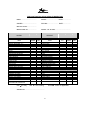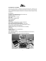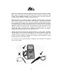
1
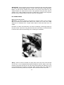
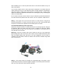
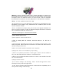
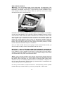
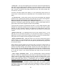
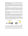
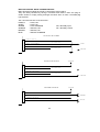
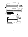
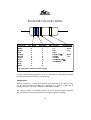
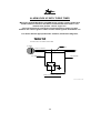
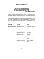
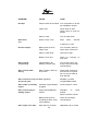
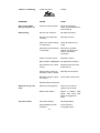
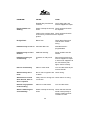
SECURITY INSTALLATION TRAINING MANUAL BASED ON AS/NZS3749.2 1997 Written and prepared by Murray Johnson for Mongoose (NZ) Ltd PREFACE This security installation training manual has been produced as a guide to help the vehicle security installer perform quality installations as required by the joint Australian/New Zealand Standard AS/NZS 3749.2:1997. Installers are encouraged to obtain a copy of this document, along with a copy of Part 1 of the Standard, which refers to the specifications and performance requirements of vehicle security systems. Because it is recognised that the vast majority of vehicular false alarms are a direct result of poor installation and maintenance of alarm systems, it is hoped that adherence to the Standard, together with reference to this Security Installation Manual, will significantly reduce the number of false alarm incidents. The Standard requires that the installation of a security system must be carried out only by competent persons who are accredited by a manufacturer/supplier or an authorised competency assessor, to install the appropriate VSAS (Vehicle Security Alarm System) or VSIS (Vehicle Security Immobiliser System). A competent person is referred to as a person who has acquired through training, qualification, or experience, or a combination of these, the knowledge and skills enabling that person to perform the tasks required by this Standard. This manual is not intended to be a total source of information and installers are encouraged to research other material such as; Mobile Electronics Retailer magazine (formally Installation News) - it is also available on the Internet; Mobile Electronics Certification Programme Study Guide (Security Specialist); Car Audio and Electronics magazine; basic electronics books; security training manuals from other distributors, etc. DO IT ONCE AND DO IT RIGHT - This means no short cuts. You never get paid twice for having to do the job twice because it wasn’t done right the first time. 2 The Recognised Name In Security TABLE OF CONTENTS 1. SET UP AND DOCUMENTATION Pre-installation Inspection Preparation/Research Vehicle inspection sheet Safety Recommended Equipment PIN codes Immobiliser relays Page Page Page Page Page Page Page 4 4 5 6 7 9 9 2. PERFORMING THE INSTALLATION General Installation and Wiring Techniques Under the Bonnet In the Main Cabin Programme switch & sensors Main Control Module Central Locking Testing the System Finishing Off Page Page Page Page Page Page Page Page 10 12 14 15 19 23 29 30 3. INSTALLATION TIPS Relays Diodes Resistors Capacitors Universal Timers Miscellaneous Tips Page Page Page Page Page Page 31 32 33 34 35 37 4. FAULT DIAGNOSIS Current Draw Test Page 39 Page 43 5. MX750S Code learning Programming Feature list Wiring diagram Page Page Page Page 3 45 46 47 48 The Recognised Name In Security SET UP AND DOCUMENTATION PRE-INSTALLATION INSPECTION Quality installations start well before any physical work begins on a vehicle. A vehicle inspection should be carried out prior to starting the installation and preferably before the owner of the vehicle has left the premises. This will ensure that you are not accused of damaging something in the vehicle that was already damaged before you started. It may also help to identify any possible problems with the vehicle that will either need to be rectified prior to installation, or require extra time. If you find any defect which is of a significant nature it would be advisable to bring it to the attention of the owner, or have the inspection sheet witnessed by someone else, prior to starting installation. It is also advisable to carry out a post-installation inspection which may identify any problems that have occurred during installation. Enclosed is a sample of a vehicle inspection check list which can be used, or you may wish to create your own. Factory Fitted Equipment - If the vehicle is equipped with an airbag, or has a coded stereo system, make sure that you have the information available to disconnect and re-install these systems. Current Drain Test - How many times have you had a customer come back to you saying the alarm is draining the battery flat? Doing a current drain test is something that most installers never do until that scenario arises. Performing a current drain test before you start an installation may well identify any problems within the vehicle before you start. Typically, the idle current draw in a vehicle would range from 10-30mA. The typical current draw of a security system is about 20-30mA and is not enough to drain a battery over a few days or even a few weeks. However, if there is already a current draw of say 60-100mA, then you will have a problem when you add the security system. Current draw of over 100mA can drain a battery over a few days. Refer to the Fault Diagnosis shooting section of this manual. PREPARATION VEHICLE RESEARCH Much time can be saved on an installation if the relevant information relating to the wiring in the vehicle is obtained first. This information can be obtained from numerous sources; vehicle service manuals, after-market workshop manuals, computer software and personal documentation. Mongoose maintains a database of vehicles known to have had Mongoose alarms installed. This information is available to authorised dealers from our website www.mongoose.co.nz A user name and password is required to enter this site. 4 The Recognised Name In Security PRE/POST-INSTALLATION VEHICLE INSPECTION MAKE.................................... MODEL.......................... YEAR................... OWNER................................ REG NO......................... DATE.................. INSTALLED BY..................... INSPECTED BY.................... MODEL OF ALARM.................................... ALARM ITEM REMOTE RESPONSE X 2 CDL (IF CONNECTED) CHIRP INDICATOR RESPONSE PANIC VALET VALET BY REMOTE MICROWAVE BEAM SIZE SHOCK SENSITIVITY PRE-INTRUSION NITE LITE BONNET, BOOT, DOOR TRIGGER PASSIVE ARM BONNET PIN SWITCH POSITION ANTI HIJACK PASSIVE LOCK REMOTE BOOT RELEASE SENSOR DISABLE ULTRASONICS A.E.D. OPERATOR GUIDE WINDOW STICKERS WARRANTY CARD INVOICE & PAYMENT VEHICLE PASS FAIL ITEM PRE/POST INSTALL TEST PASS PARK LIGHTS CDL HEAD LIGHTS INDICATORS RADIO CELL PHONE HEATER FAN HORN POWER WINDOWS AIR CONDITIONING WIPERS - ALL SPEEDS ELECTRIC BOOT RELEASE HAZARD FLASHERS INTERIOR LIGHTS INTERIOR DOOR LIGHTS REAR WIPER ELEC. SUNROOF DOOR SWITCHES X 4 VEHICLE CHECK FOR TIDINESS & TOOLS UNDER BONNET INTERIOR BOOT DASH PANELS DOOR PANELS BODY PANELS OWNER CONTENTS EXPLANATION TO OWNER OF FEATURES AND OPERATION Use ‘ ’ if okay. Use ‘X’ if not working. Use ‘N/A’ if item not applicable. SIGNED BY ............................................ 5 FAIL The Recognised Name In Security WIRING INFORMATION Whilst every effort has been made to ensure the accuracy of the information, due to constant changes in vehicle manufacturing and sourcing of components, colours and locations may vary. MONGOOSE TAKES NO RESPONSIBILITY OR LIABILITY FOR INCORRECT INFORMATION PRINTED IN THESE FILES. ALWAYS VERIFY INFORMATION USING A MULTIMETER. NEVER USE A TEST LIGHT. Cross reference all information. The best source of information is your own files because experience is the best teacher. If you don’t keep records then you should begin right now. Not only will it help you in future installations but you can help us to keep their files up to date. SAFETY With the interests of the customer in mind, always ensure that every precaution is taken to safeguard the vehicle by using guard protectors and drop mats to catch any possible solder spills. Make sure the vehicle is parked with the handbrake on and is left out of gear, with the drivers window open. (One day an installer was testing the start disable function on a car only to have the vehicle drive straight into a vehicle hoist causing extensive damage to the front guard.) Make sure you have sufficient room around the vehicle to fully open the doors. 6 The Recognised Name In Security RECOMMENDED EQUIPMENT It has often been said that “a workman is only as good as his tools”. Make sure you have the appropriate tools for the job and know how to use them correctly. Below is a list of recommended equipment required as a minimum to perform quality security installations: MULTIMETER SUITABLE SOLDERING IRON (ELECTRIC AND GAS) SUITABLE FLUX CORE SOLDER INSULATION TAPE SELECTION OF HEAT SHRINK HEAT GUN INSULATION LOOMING TAPE WIRE STRIPPERS SIDE CUTTERS CRIMPERS SELECTION OF APPROPRIATE CRIMP TERMINALS SELECTION OF AUTOMOTIVE CABLES ELECTRIC HAND DRILL (MAINS AND/OR CORDLESS) SELECTION OF APPROPRIATE HIGH SPEED METAL DRILLS SOCKET SET (METRIC AND IMPERIAL) SCREW DRIVER SET (FLAT HEAD AND PHILLIPS HEAD) TORX SET ALLEN KEYS SPANNER SET (METRIC AND IMPERIAL) STANLEY KNIFE TRIM REMOVING TOOLS PULL THROUGH CORD (e.g. CURTAIN WIRE AND/OR OLD CAR AERIAL) VACUUM CLEANER FLURO’ LEAD LIGHT (BULB TYPES CAN BURN CARPETS) 7 The Recognised Name In Security Never use a simple incandescent (bulb) test light to probe a vehicle’s wiring. Many modern cars today have sensitive electronics and using a “dead short” type of probe may immediately damage, or set in motion to fail in the future, electronic systems such as airbags or computers within the vehicle. When you probe a circuit with a test light or voltmeter, the device that you are using becomes part of that circuit and adds an additional load. Test lights, on average, have an input impedance of 100 to 200 ohms, whereas a typical voltmeter has an input impedance of 10 million ohms. Some quick math shows that when a test light is connected between chassis ground and a point in a vehicle circuit, it will add an additional 120mA current draw to the circuit (assuming 12 volts and the use of an average test light). A test light with a higher input impedance will have a lower current draw. Using the same math to calculate the current draw of a voltmeter, installers will find that it adds only .0012 mA to the circuit. Although logic-safe test lights have gained popularity in recent years, voltmeters and multimeters have two distinct advantages. Logic-safe test lights do not give the voltage reading of a circuit; they only determine if it is positive or negative. And from an economic standpoint, installers can purchase a good voltmeter for about the same price as a logic-safe test light. So, if you don’t own a good voltmeter or multimeter, go out and buy one and learn how to use it properly. X 8 The Recognised Name In Security OTHER DOCUMENTATION The Standard requires that the customer receives a copy of the Operating Instructions along with a copy of the Installation Certificate. Make sure that such instructions are in the box with the product and then put them in the vehicle where the owner will see them. Better still, partly fill out the warranty card or proof of purchase for the customer and present it to them when giving a demonstration on how the security system operates. Mongoose products also include a ‘proof of purchase’. This is to be completed and retained by the customer in the event of a warranty claim. The Installation Certificate must include the installer’s licence number where appropriate. As all Standards Certified products must be fitted in accordance with Part 2 of the Standard, all installers need to be accredited by the distributor of the product or be a member of the NZSA. PIN CODE Standards Certified models use a PIN code to override the system in the event of loss, damage or non-operation of the remote controls. Each system differs in the method of override and this information is in the owners operator booklet. They are supplied with a ‘card’ quoting the factory set PIN code. Ensure the customer keeps this safe and in a place where they can find it, but in the vehicle unless it is well hidden. Mongoose does not record PIN codes. If the card gets lost, the PIN code may be printed on the inside of the system module which can only be accessed by disassembling using a security TORX screw driver. Models like the M80 Series can be re-programmed with the customers own number. This deletes the factory setting and it cannot be defaulted back. Once reprogrammed the factory setting is lost. IMMOBILISER RELAYS NZ Standards specify ‘normally open’ immobiliser relays. Essentially this means that the relays are always open circuit unless the engine is running. In the disarmed state, the ignition input closes the relays to allow the engine to be started and then to run. At all other times, they are open thereby immobilising the engine. Power or ground removal just makes matters worse for a thief as power is needed to close the relays to get the engine running. The loss of power and/or ground whilst the engine is running will cause the engine to stop. For this reason, Mongoose system have 2 separate ground wires (which you connect to 2 different ground points) and at least 3 power supplies :- main power, ignition input (power taken off this input as a back-up) and power taken off at least one of the circuits being immobilised. The chances of power or ground loss whilst driving is therefore drastically reduced – providing you do your installation correctly. 9 The Recognised Name In Security PERFORMING THE INSTALLATION First things first - wind down the drivers side window and remove the ignition keys from the ignition. Many an installer will tell you about the one time they forgot to do this and accidentally locked the keys in the car when they first tested the alarm, only to find they had not connected to the correct unlock wire for the central locking. Also, fully turn off the interior light to avoid draining the battery. Remember - the security system is only as good as the installation. PLAN YOUR INSTALLATION Before you begin to install any components of the security system into the vehicle think about where you are going to mount them. Think about what you want to achieve as an end result. Having a plan and a system of doing things will eventually save you time, with less hassles, and the customer will have a security system that is reliable and will perform to specification. Planning the location of the components will also result in saving time and make the system more secure. Once you have decided on the locations for mounting the product start under the bonnet and work your way back to the boot. That way your wiring loom will flow and look like it is part of the car. GENERAL INSTALLATION AND WIRING TECHNIQUES Before we begin the installation of a reliable security system let’s look at some of the techniques used that contribute to a quality installation. The key word is “security”. Anyone can put a security system into a vehicle in next to no time at all. However, it may well turn into just an alarm system, i.e. the alarm may sound when a thief breaks into it, only to stop shortly after due to the fact that the alarm control module was easily found under the dash and unplugged; or the override switch was easily found and the ignition barrel was ripped out with a slide hammer; or the bonnet was opened and the siren wires cut, or were accessed easily from under the car prior to breaking into the vehicle. The key to turning an alarm system into a security system is concealment. Make it look as though it is part of the vehicle. Hide the control module where it cannot be found without removing a number or panels first. Use looming tape and/or convoluted tubing to conceal the wiring harness so it blends in with the factory looms. 10 The Recognised Name In Security Take care when removing trim panels. If you don’t know how something comes apart seek advise from someone who does. The “rip, tear and bust” method is not convivial to quality installations. Wiring Techniques - Apart from making your loom blend into the vehicle it is most important that, where you interface your security system loom with the vehicle’s electrical system, you use the correct jointing techniques. * Never use “Scotch-Lock” connectors - these clamp-on type connectors do not provide a good contact. If using crimp connectors make sure you use the right typeof crimping tool - not pliers. The Standard (AS/NZS 3749.2:1997, 2.5.4.1) forbids the use of Scotch-Locks. * The best way to connect the security system wires to the vehicle is by using the strip and solder method, followed by heat shrink or proper looming tape - not Sellotape or packing tape. Yes, you may well laugh but some of the worst installations seen have been done with such items. Wires should never be simply twisted together and taped over, they do not create solid wire connections and you are only courting disaster. When soldering your connections make sure that the solder flows right through the joint - not just tacked on. When soldering onto thick wires, such as power, ignition and starter wires, make sure you have sufficient heat in your soldering iron to allow the solder to flow right through the joint. * When extending wires, or adding power or earth cables, always use the appropriate size cable for the job. If a wire is too thin there is a chance you will have voltage drop which may affect the performance of the security system. The longer the cable the larger diameter it will need to be. * Where you have to cut into a taped loom to make your connections make sure you retape the loom to make it look like factory again. * Use fuses, even if they do not come in the kit. 11 * Secure all looms with cable ties to existing looms or vehicle framework so that they blend into the car. This will prevent wires from falling down and becoming exposed to a would-be thief. * Also conceal and solidly secure all security system components so they do not fall down and become visible to a would-be thief, or become a potential safety hazard. When drilling mounting holes remove all swarf from the hole and the vehicle, and protect holes using recognised anti-corrosion treatment. * Always verify wiring information you have obtained, from whichever source, with a multimeter before making connections. Never “ASSUME” anything - it just may make an “ASS” out of “U” and “ME”. * Make sure the power and earth supplies are good, as the operation and reliability of the security system depends on this. Many intermittent problems with alarm systems are due to poor power and earth supplies. * Read the Operator’s Manual; it provides good working knowledge of the security system. The length of time that an installer will wait on the phone on hold in order to ask a question that he could have obtained from the manual is a scientific phenomenon that we can’t explain. UNDER THE BONNET PIN SWITCH Mounting - Mount the bonnet pin switch so that when the bonnet is closed the top of the switch is hitting a flat surface. If it hits on a sloping surface it may break off or have intermittent false alarms. Never mount the switch in a water channel as this will only result in false alarms every time it rains. Never mount the switch in a place where it can be accessed from outside the vehicle. Wiring - Connect a wire, of sufficient length to reach into the main cabin, to the switch using a suitable connector. This wire can be black in colour to blend into the wiring within the engine bay, or you can cover it with convoluted tubing or looming tape, which ever best suits. Route the wire around the engine bay, following a path which will make it blend in and not be damaged by heat or moving parts, to the point where it will be passed through into the cabin area. Secure the loom with black cable ties to the existing wiring looms. The Recognised Name In Security 12 SIREN Mounting - Mount the siren in such a position to give good radiation of sound to the atmosphere when the bonnet is closed. However, this can be difficult in modern cars today where the engine bay is particularly full. Then it may be a case of thinking laterally. Perhaps the siren could be mounted between the inner metal guard and the plastic inner guard, providing there is adequate sound dispersion. Sometimes if you remove the battery and it’s box you can fit the siren underneath. Take care that the siren is not exposed to extreme heat such as is found close to turbo chargers and exhaust systems. Also, keep the siren away from possible damage from water which may splash up from the road and fill the horn cavity of the siren. If you think there may be a chance that water will reach the siren try drilling a small hole in the centre of the horn to allow the water to drain out. Many a time a car has come into a workshop with a quiet siren, only to find that the horn was full of water. Battery back-up sirens need to be mounted in such a way as to allow the owner of the vehicle access to turn on/off the siren if it is of the key type, otherwise it may be hidden. Take care that the siren is not easily accessed from under the vehicle by a wouldbe thief who would try to cut the wires going to it. Wiring - Connect the earth wire from the siren to a factory earth bolt, or by a separate screw to the chassis using a star washer to ensure good contact to ground. Never attach the earth wire to the siren bracket because if the siren becomes loose a battery back-up siren would start to sound while the owner is driving down the road. Once again, conceal the wires going to the siren with looming tape or convoluted tubing and route the wiring with the pin switch wire loom to the firewall, using cable ties to secure. Also, tape over any plugs to prevent moisture damage to the connectors. 13 IMPORTANT - When passing wires through the firewall into the main cabin always use either an existing rubber grommet, or drill a hole and install a rubber grommet. Before you drill into the firewall, check what is on the other side. Never run the cables between the metal and the side of the grommet. Doing this may result in chaffing of the cable insulation and cause a dead short to ground, which may also lead to not only a product failure, but also a fire in the wiring loom. IN THE MAIN CABIN LED (Light Emitting Diode) Mounting - For security reasons it is important to mount the LED in such a position that it is visible from outside both sides of the vehicle, as it acts as a visible deterrent to a would-be thief. A spare switch blank is useful but make sure it is visible. Be aware of classic and expensive cars when considering a mounting location for the LED. Some owners are very particular with their cars and it is sometimes best to discuss the location and mounting prior to starting the installation. Wiring - Where a LED is mounted in a major panel, which may have to be removed at any time, it is recommended that bullet terminals be used to allow for the easy removal of the panel. Secure the car side of the LED harness with cable ties so it is not lost behind when the panel is removed. Allow enough slack in the LED side of the loom to allow easy removal of the panel. Also secure the back of the LED. 14 PROGRAMMING SWITCH (depending on alarm model) Mounting - If a programming switch is supplied it should be mounted in a location that is able to be accessed by the owner of the vehicle. However, it should also be hidden from the thief and you should therefore discuss the mounting location with the owner prior to starting the installation of the security system. Use your imagination. Suggestions include; inside a lockable glove box; in the ash tray; under a removable ash tray (as shown below); in a heater vent; under the seat; disguised as a fuse in the fuse box. Wiring - As with the LED it is also recommended that you use bullet connectors on the switch harness to allow for the easy removal and fitting of any panel where necessary. SHOCK / IMPACT SENSOR (model dependant) Shock sensors are typically designed to detect the various degrees of impact that might be applied to a vehicle during a break-in attempt. Some are better than others since some are designed to better sample and discriminate their inputs in order to avoid false alarms. Mounting - The important point to remember when mounting a shock sensor is make sure that it will pick up impact from every area of the vehicle. Therefore, it is best mounted centrally in the vehicle. Many installers attach the shock sensor to the steering column where it may be susceptible to road vibration from a heavy truck driving by, and may false trigger. 15 Other installers put it in the kick panel area where it will then be biased to only one side of the vehicle. Try to find a location where it will not pick up the expansion of the dash when the vehicle heats up in the sun. Also make sure that it is solidly mounted. Just pushing it under the carpet or cable tied to wiring looms is not solid enough - to pick up any impact the sensitivity adjustment will need to be turned right up, only increasing the chance of a false alarm. Do not mount the shock sensor where it may be affected by electrical inductance from other electrical systems within the vehicle, such as computers, cellphones etc. Wiring - Once again do not run the loom close to an area where it may pick up electrical interference. If it does not have a plug-in loom to the control module keep the power and earth wires separate from the alarm power and earth. ULTRA-SONIC SENSOR (model dependant) Ultra-sonic sensors consist of a sender and receiver unit that pick up the change in air pressure within the cabin area when a door is opened or when they detect movement within the cabin. They are therefore not suitable for convertible cars as they will detect air movement. Mounting - Mount the sender and receiver heads at the top of the windscreen pillars facing them to the centre rear of the vehicle. Run the cables attached to them down the pillars making sure that they do not get snagged by any trim clips or crushed by the trim panels. Route the cables to the ultra-sonic module using cable ties to secure them. Wiring - Once again unless the module has a dedicated plug to the alarm control module keep the power and earth supplies separate to the alarm power and earth. Also, do not use the shock sensor power and earth. 16 MICROWAVE SENSOR (model dependant) Microwave (or Radar) sensors work in a similar way to ultrasonic’s in that they send out a signal and monitor its return. The advantage over ultrasonic’s is that they do not detect any change in air pressure and are therefore better suited to convertible vehicles. Mounting - Microwave signals will travel through virtually everything except metal so it is important that you consider the mounting location of the sensor carefully to avoid any ”shadows” from dashboards, consoles, handbrakes, switches etc. They also work better and are more stable in their performance if they are mounted directly onto a flat surface. Therefore, the best place to mount a microwave sensor is in the roof facing down as there are no shadows and have an unobstructed “view” of the cabin interior. Be aware though that the headlining in some cars contains aluminium foil in their construction which will block the signal. Attaching the sensor to the roof lining is preferred as to mounting to metal of roof as the high temperatures in the summer can cause sensors to false or even fail completely. Other location options are the centre console area, although you must keep the sensor away from spare keys or coins and electric switches, or the front of the vehicle facing to the rear, or behind the back seat facing forward. Another consideration in mounting a microwave sensor is that it must be mounted along the centre line of the vehicle to give even detection coverage of the interior of the vehicle. As this position is not always acceptable or viable one other area is to mount under either front seat, adjusted accordingly. Wiring - It is most important that the earth wire to the sensor is kept as short as possible and grounded . The earth wire must not be connected to the alarm control module earth. Once again the power supply wire to the sensor must also be separate from the alarm and shock sensor power supplies. GLASS BREAKAGE SENSOR (model dependant) These sensors detect the frequency of breaking glass. Some sensors can be unreliable if they do not contain an analysing circuit and can false alarm when detecting certain ambient noises such as emergency vehicle sirens, jet engine noise from aircraft, or some loud motorbikes. 17 Mounting - As these sensors usually have an external microphone to detect noise the microphone must be mounted so it can ‘hear’ the whole vehicle. Do not hide the microphone under the dashboard. Mount the control module under the dashboard but somewhere accessible so sensitivity adjustment can be made after installation. Wiring - The same guidelines as previous apply. The best advise for any sensor placement is to follow the recommendations of the manufacturer of the product. Every manufacturer has a different opinion on how sensors should be mounted. There is no substitute for proper testing. It is crucial for the proper installation of a sensor. It’s better to spend an extra five minutes testing the unit than to come back and be embarrassed with the customer there. 11 Sensor Techniques to Avoid Common Pitfalls 1) Know what the sensor does. 2) Don’t expect too much from the sensor. 3) Find out exactly what the customer wants the sensor to do. Ask lots of questions. 4) Avoid improper placement of the sensor: e.g. installing a shock sensor in the drivers kick panel, where it will be too sensitive on one side of the vehicle and not sensitive enough on the other. 5) Never mount alarm system components near computers. 6) Always test. There is no substitute for proper testing. 7) There is no optimum spot where a certain type of sensor can be installed in every car. Placement should be made on an individual basis. 8) Never mount multiple microwave sensors too close to one another since this can cause interference. 9) Always read the manual. 10) Fix sensors solidly to the mounting surface. Avoid over-tight shock sensor mountings as body creak can trigger them. 11) Use sensors from the same manufacturer as the alarm for compatibility and to avoid possible voiding of the warranty. 18 MAIN CONTROL MODULE Mounting - The new Standard states “where practicable, all components of the VSAS shall be concealed”. This means you cannot see it or grab hold of it ! Remember concealment is the key to a good security system installation. Since most installers mount the brain module under the dash near the fuse box, that’s exactly the first place a thief would look. Remember that a security system is only as good as the installation. As installers, we have a moral obligation to the customer to perform installations with the security of the vehicle in mind, rather than what is easiest for us. Therefore, choose a more secure location, such as behind the glove box (photo above-module is above the dash support tube) or behind the centre console, in an area that requires the removal of several panels to gain access. As Mongoose Standards approved products are programmed via the ignition input the control module can be completely hidden. The only internal jumpers on some models control door polarity or a turbo function and these should be set prior to installation. Once you have decided where you are going to mount the alarm brain module you are now ready to make your loom and interface with the vehicle. IMPORTANT – UNPLUG THE MAIN ALARM FUSE (OR WHOLE LOOM) AND DO NOT INSERT IT UNTIL ALL CONNECTIONS HAVE BEEN MADE AND CHECKED. If the module or fuse is plugged in first there is a great risk that you will blow up something in the brain module if a wrong connection is made. Always connect earth circuits first before any other connections are made. Wiring - Start covering the alarm wiring harness with electrical looming tape from the module making sure there is no stress. Make the loom flow logically and to look like factory looms, branching out at the various necessary points. Always think ahead so that you can add any additional wires for accessories or relays etc. so that you save time and tape. Trying to tape up a harness after it is installed into the vehicle will only lead to a complete mess. Cut off any excess cables, or tape into the loom - do not push any excess up under the dash and hope it doesn’t fall out; you will only end up with a “bird’s nest”. 19 * Power wire - The wire that supplies power to the brain should be a dedicated wire and should not be tapped onto for supply to any other sensors or relays. This will avoid any voltage drop problems which may upset the microprocessor in the alarm brain. All other accessories and relays should have their own power supply wire, each with its’ own fuse. Connection should be made at the battery or to any permanent power source in a secure area. It should also have a dedicated fuse or circuit breaker with the correct rating. * 2 x Ground wire - Ground wires need to be as short as possible and should be attached to two separate solid chassis points that are free of paint, dirt and grease. Never connect the ground wires to the same chassis point. Standards products use ‘normally open’ immobiliser relays and loss of a common ground (if connected at same point) will cause the engine to stop whilst driving. 2 ground wires are therefore supplied to reduce this possibility. A good ground connection will measure less than 0.1 Ohm. Metal supports under the dash are sometimes isolated from the body of the vehicle with nylon or plastic washers, as can be steering columns. Just because it’s metal doesn’t mean it’s a true ground. Always test with a multimeter. Always use star washers to ensure good contact. * Ignition sense wire - It is important that you find a “true” ignition source, i.e. one that stays at 12 volts when the ignition is on and when the engine is cranking, as apposed to accessory wires which will drop off while the vehicle is in starting mode. The ignition wire is usually found at the ignition switch harness. * Starter immobiliser wire - Whilst the starter wire can also be found at the ignition switch harness, it is recommended that you connect the alarm starter immobiliser wires at a different location as this is the first place a potential thief is going to look to hot wire a vehicle. When testing to find the starter wire it will only have 12 volts on it when the key is turned to the starting position and have 0 volts when the key is in the run or off positions. Be aware though, that automatic vehicles may have what appears to be two start wires, the second being the start inhibit wire from the transmission lever switch. So when you have found what appears to be the start wire, cut the wire and try to start the vehicle. If the vehicle still starts then rejoin the wire and find the correct one. * Other engine immobiliser wires - As the Australian/New Zealand Standard requires at least two independent electrical means of preventing movement of the vehicle under its own power, another circuit as well as the starter motor circuit needs to be considered. Options include fuel pump circuit or the ignition circuit (or diesel engine glow plug circuit), or transmission lock out solenoid. The 2003 Installation Standard requires that the 2 immobile cuts are at least 300mm apart from each other. Vehicles with catalytic converters should never have the ignition system immobilised without the fuel system also being immobilised. Failure to disable the fuel system could result in unburnt fuel entering the catalytic converter and cause extensive damage. 20 Words of caution – ALWAYS CARRY OUT A CURRENT DRAW TEST ON ANY CIRCUIT BEING IMMOBILISED TO ENSURE IT IS WITHIN THE CAPABILITIES OF THE SECURITY SYSTEM. A two or three point immobiliser has an awesome responsibility to perform. Therefore, it is imperative that where the alarm interfaces with electrical circuits in the vehicle for the immobiliser function, your joints must be perfect. Whilst the failure of a starter circuit may cause a little inconvenience to the customer, the failure of the ignition or fuel delivery system may have catastrophic consequences. * Light flash wires - If the security system manufacturer specifically states that the alarm must be connected to the park lights, do not try to connect to the indicators (which may invalidate the product warranty) as the current draw may burn out the systems light flash relay. This in turn may burn out light bulbs, and/or flatten the vehicle battery. A lot more current is drawn flashing indicators than flashing park lights. Park light and indicator wires are commonly found at the steering column harness or the control relay. They are usually positive switching but can sometimes be negative. Watch out also for some cars, usually European, that have separate left and right side park lights. * Door pin switch wire - Most vehicles use a negative switching system for dome light control, although there are some vehicles that use positive switching, e.g. early model Ford Falcons. This wire can commonly be located in the kick panel area, or windscreen “A” pillar, or under the dash at the instrument panel if the vehicle has a door display or door open warning light, e.g. Honda Accord or Subaru Legacy. When testing for a door trigger wire make sure that the wire you have found works when each door is opened, not just the driver’s door. A negative switching type will show 12 volts when the door is closed and 0 volts when the door is opened. Conversely, if it is a positive switching system, the wire will show 0 volts when the door is closed and 12 volts when the door is opened. POSITIVE DOOR TRIGGER NEGATIVE DOOR TRIGGER Dome Light Dome Light 12 volts 12 volts Door Switch Door Switch Be aware of vehicles that have one wire for the front doors and another for the rear doors. Connect the alarm wire to both of these wires using diodes to isolate the two circuits. Some vehicles have separate wires for each door, e.g. BMW 5 Series. Also make sure that the wire does not have a permanent ground on it when the dome light control switch at the light is switched to the full off position, as this may 21 cause the alarm to trigger on setting, or give a warning via the siren that the door is open when in actual fact it is not. Do not connect the boot to the door wire as, depending on which model of alarm, this will give the wrong diagnostic code on the alarm LED if the boot is opened when the alarm is set. * Boot wire - Most modern cars have a boot light which will work on the same principle as the door wire. Test the same as for the door wire. Some cars, particularly hatch back models, are already factory connected to the door circuit. If the alarm has a dedicated boot wire then it can be connected directly to the boot light control wire. If not, then the boot light control wire should be connected to the bonnet wire using a diode to isolate the two circuits and stop the opening of the bonnet turning on the boot light. The diode will also prevent the battery from flattening itself if the bonnet switch becomes faulty. Once again, do not connect the boot light control wire to the doors. * Central locking wires - This is an area which a lot of installers find most frustrating. The trick is to identify which sort of system is employed in the vehicle. Basically there are only a handful of different factory door lock circuits which fall into distinct categories, such as Negative Pulse, Positive Pulse, and Reverse Polarity. A few systems use Vacuum and/or Vacuum/electric designs. More recently there are some vehicles which use a single wire system, with an open circuit to lock and a negative pulse to unlock (or visa versa), or dual voltage switching. The first thing to do is establish that there is a solenoid (commonly called a ‘door motor’) in the driver’s door. As a general rule of thumb, if you can fully lock the whole car by using the key in the front passenger door, or if there is a switch inside that will do the same, then there will be no need to install an extra solenoid in the driver’s door. However, there are some vehicles that this theory does not work on; so be aware. The next thing to do is establish which switching system is employed. Remember that all your interface has to do is duplicate the action of the factory door lock switch(es), even if they are located in the door lock actuators themselves. Using your multimeter, find out what is happening on the central locking wires. Then test which wires you think are the correct wires using a 1A fused wire for negative or positive switching. That way if you’ve got the wrong wires, all you will do is blow the fuse and not the central locking control module. As a general rule, switching wires are usually thin wires and motor wires are of thicker gauge. If the security system you are installing does not have on-board central locking relays, but instead has low current negative output wires, take care when trying to connect to some negative switching systems. Some cars, like the early Ford EA Falcon, require a high current negative pulse to work the central locking, so you will require additional relays. If you find it appears to be neither negative or positive, then it may be reverse polarity, such as is found in Ford XE Fairmont. This will involve cutting the two solenoid control wires and putting them through the normally closed contacts of the alarm interface relays, wired so that the alarm will break the contact and feed a positive pulse to the door solenoid for lock and unlock. The factory switch will then operate the other doors. Some installers refer to this as the “flow through method”. 22 BUILT-IN CENTRAL DOOR LOCKING RELAYS Many Mongoose models have built-in central door locking relays. They are easily identified by having 6 coloured wires either in their own plug on earlier models or simply exiting amongst the black wires on later concealed plug type systems. The colour and function of the wires are:PURPLE - LOCK, NO WHITE - LOCK, NC GREEN - LOCK COMMON ORANGE - UNLOCK, NO BROWN - UNLOCK, NC BLUE - UNLOCK COMMON NO = Normally open NC = Normally closed N E GA TIV E SW ITC H IN G P U R PL E - L O CK N O MX50 W H ITE - L O CK N C N O C O N N E CTIO N G RE EN - L O CK CO M M O N O R A N G E - U N L O CK N O B RO W N - U N L O CK N C . N O C O N N E CTIO N B LU E - U N LO C K CO M M O N U N LO C K P OS ITIV E S W ITC H IN G MX50 +12 V OL TS . PU R P LE - LO C K N O W H I TE - LO C K N C N O CO N N E CT IO N GR EEN - LO C K C OM M O N LO C K O R A N G E - U N LO C K N O B R OW N - U N LO C K N C N O CO N N E CT IO N B LU E - U N LO C K C O M M O N U N LO C K R EV ER S E PO LA R ITY +12 V OL TS . P U RP L E - LO C K N O W H ITE - L O CK N C MX50 LO C K G R EE N - L O CK CO M M O N TO C A R TO D OO R O R A N G E - U N L O CK N O B RO W N - U N L O CK N C TO C A R B LU E - U N LO C K CO M M O N TO D OO R 23 +12 VOLT ADD ON SOLENOID PURPLE - LOCK NO . .. MX750 WHITE - LOCK NC GREEN - LOCK COMMON ORANGE - UNLOCK NO BROWN - UNLOCK NC BLUE - UNLOCK COMMON . . . TO CDL MODULE TO SWITCH SINGLE WIRE SWITCHING CDL CONTROL WIRE PURPLE - LOCK NO NO CONNECTION . MX750 WHITE - LOCK NC GREEN - LOCK COMMON ORANGE - UNLOCK NO BROWN - UNLOCK NC CUT FACTORY WIRE NO CONNECTION BLUE - UNLOCK COMMON THIS SYSTEM USES AN OPEN CIRCUIT TO LOCK AND A NEGATIVE PULSE TO UNLOCK. SOME CARS MAYBE NEGATIVE TO LOCK AND OPEN CIRCUIT TO UNLOCK. VACUUM PUMP SYSTEM FACTORY VACUUM PUMP USUALLY FOUND IN BOOT OR UNDER REAR SEAT .. GREEN - LOCK COMMON ORANGE - UNLOCK NO BROWN - UNLOCK NC BLUE - UNLOCK COMMON TO +12 VOLTS VIA FUSE GREEN BLUE PURPLE - LOCK NO MX750 YELLOW WHITE - LOCK NC NOTE2: MOST MODERN VACUUM SYSTEMS NOW USE 1 SECOND NEGATIVE SWITCHING CDL. TAKE CARE BLACK/YELLOW GROUND RED NOTE 1: BE SURE TO PROGRAM ALARM BRAIN FOR 3 SECOND CDL PULSE BROWN . . CUT FACTORY WIRES CLOSE TO PUMP BLUE GREEN TO FACTORY FUSED 12 VOLTS 24 Some models have the option of 2 stage unlock. This is where the 1 st press of the remote just unlocks the drivers door and a 2 nd press, within a few seconds, unlocks the remaining doors. M80 2 stage unlock DRIVERS DOOR 87 2nd unlock from module 85 87a 86 OTHER DOORS + 12v 30 Ground Passenger door motor(s) unlock wire PURPLE ---------------- 12V POSITIVE WHITE----- ------------- GROUND GREEN------------------LOCK ORANGE----------------12V POSITIVE BROWN- --------------- GROUND BLUE------- ------------- UNLOCK BLACK-------------------2ND UNLOCK WIRE 12V RELAY AS ABOVE For other configurations, please refer to the main Mongoose installation manual (red folder) or view on our web site. www.mongoose.co.nz 25 On models which do not include built-in relays, 2 x 5 pin relays can be used to achieve the same operation. These are sold by mongoose as a kit, MLP550, and the relays are pre-wired ready for connection. NEGATIVE TRIGGER DOOR LOCKS Door Lock Switch . .. . . Factory Door Lock Module Door Lock Motors 12 V+ Fused . 87 (-) Door Lock Trigger 87a 85 These relays may be on-board the alarm module 87 (-) Door Unlock Trigger 87a 86 30 86 30 85 POSITIVE TRIGGER DOOR LOCKS 12 v+ Door Lock Switch . .. . . Factory Door Lock Module Door Lock Motors . (-) Door Lock Trigger 85 12 V+ Fused These relays may be on-board the alarm module . 87 87 87a 87a 86 30 86 26 30 (-) Door Unlock Trigger 85 REVERSE POLARITY DOOR LOCKS Driver’s Side is Master Switch 12 v+ Passengers Lock Switch .. . .. . Driver’s Door Lock Switch . (-) Door Lock Trigger .. . .. . . Cut Factory Wires 12 V+ Fused These relays may be on-board the alarm module . 87 87 87a 87a 85 30 86 86 Door Lock Motors 30 (-) Door Unlock Trigger 85 MERCEDES BENZ VACUUM SYSTEM Factory Vacuum Assembly (Usually found in boot or under the back seat) 87 (-) Door Lock Trigger 87a 85 30 . 87a 85 30 Yellow Brown 86 87 (-) Door Unlock Trigger Black/Yellow Green Red . . Blue These relays maybe on-board the alarm module 86 Cut factory wires close to pump Blue To Factory Fused 12 V+ 27 Green ONE WIRE DOOR LOCKS Cut Factory Wire . .. Door Lock Switch Factory Door Lock Module Door Lock Motors This relay may be on-board the alarm module 12 V+ . 87 (-) Door Lock Trigger 87a 85 30 (-) Door Unlock Trigger 86 This system uses an open circuit to lock and a negative pulse to unlock. Some systems are reversed. Some factory interfaces will require the addition of a solenoid to lock the driver’s door at the same time as negatively switching the central locking control module in the vehicle, e.g. some Volvo, Subaru and Nissan models. If you have established that there is no solenoid in the driver’s door, then mount one in the door with the following considerations: - Make sure that the solenoid operates freely with the rod connected to the door lock rod, and is pulling on the right angle. - Protect the solenoid from possible water damage. - It is recommended that you use “Loctite” on the attachment block screws, and do not over tighten them, as you may just break the block. - Make sure that the window goes up and down without contacting the solenoid. - Secure the loom from the solenoid so that it does not get caught in the window winder mechanism. - Use the existing wire tubing to run the solenoid wires into the car. Where possible use factory type connector pins and spare holes in the door connector blocks. - Do not run the wires out between the door trim panel and the door frame. If it is too difficult to run them through the factory boot do not run them straight across to the door frame as they will eventually break over a period of time. Instead run them on an angle to minimise the flex. If necessary drill a new hole in the door frame making sure to use a rubber grommet and anti-corrosion chemicals. - Do not put the door trim panel back on the door until after you have tested the operation of the solenoid. Also check the operation once the trim panel has been put back on. Make sure that there is no binding of the solenoid or the rod. 28 ADDING AFTERMARKET DOOR SOLENOIDS These relays may be on-board the alarm module 12 V+ Fused (-) Door Lock Trigger 87 87a 85 . . 86 30 . (-) Door Unlock Trigger . 87 87a 85 . 86 30 Once again it must be stressed that if you have obtained wiring information from sources other than your own files, verify that information with a multimeter before making any connections. TESTING THE SECURITY SYSTEM Once you have made and tested all the connections from the security system to the vehicle, you are now ready to insert the main fuse or plug in the main wiring loom and test the system. It is most important that you read the operators manual and understand how each type of system works. You can then test and verify that every feature of the security system is performing to the manufacturer’s specifications. Program any options that the customer has requested before testing the system. It may also be a wise precaution to relearn the remote controls into the system to verify operation. First, make sure you have taken the keys out of the ignition and you have the remote controls, plus you have opened the driver’s window. Arm and disarm the security system and observe that the lights flash and, if the alarm is connected to the vehicle’s central locking system, locks and unlocks the vehicle. Check that the LED is also functioning and that the siren chirps, or is not chirping in accordance with the customer’s programming instructions. Rearm the system and wait about ten seconds before opening a door to trigger the alarm. If it doesn’t trigger check that you found the correct door wire. Retest for each door, bonnet and boot circuit. 29 Check that any additional sensors are working, and set up the sensitivity to give adequate protection without being over sensitive so that false alarms are minimised. Check that the engine immobiliser feature works. The LED should start fast flashing as soon as the ignition is turned off. It must them arm after 30 seconds. Check that the pin code override works according to the instructions. Check that the remotes operate the system from a good range. Check the range again once the brain module has been mounted. Attach the window warning stickers, preferably to a non-moving window, to give additional visible deterrence. FINISHING OFF When you have finished setting up the sensitivity, and fully tested all the features of the security system, mount the alarm module in the secure location you have chosen. Make sure that the aerial wire is not taped into the wiring harness and is hanging free and kept away from being surrounded by too much metal. This will ensure that it will have the best remote range possible. Refit any trim panels that were removed, repairing any that may have been broken in the course of the installation. If you can’t fix them, own up to the customer and arrange for a replacement. That’s what public liability insurance is for. Remove any wire clippings, swarf and installation materials, including your tools, from the vehicle and vacuum the carpet. Wipe off any hand prints from the glass and body work. Fill out the warranty card and leave with the operator’s guide on the front seat where the customer will notice them. Important - Perform a post-installation inspection and check that all factory electrical systems in the vehicle work. Reset any clocks, the radio security code and air bags. Do a current draw test to verify that the security system does not draw excessive amounts of current from the battery. Finally, make sure the customer is given a demonstration on how to operate the security system, making sure to demonstrate the PIN code override. Give them the owner’s manual stressing that they read it carefully. Advise them to keep the PIN code card safe but not in the vehicle. Most operator problems come about from not reading the manual. 30 INSTALLATION TIPS In this section we will discuss some of the various tools and devices available to the installer that will aid him/her in interfacing the alarm to the vehicle. RELAYS What is a relay? - In simplistic terms, a relay is merely a mechanical switch which is controlled by the magnetic field from an electromagnetic coil. Once you have an understanding of how a relay works their applications are only limited by your imagination. A central locking control module incorporates relays, as does a power window control module, and, without getting too involved with all the other components in those devices, you could quite easily build one of these using only relays. Within a relay there are two primary components; an electromagnet and a switch. The electromagnet, or coil as it’s commonly known, consists of wire wound around a core material. By connecting power to one end of the coil and ground to the other, the electromagnet will become energised, creating an electromagnetic field surrounding the coil. This will cause the switch to operate and change the contacts from the normally closed position to the normally open position. When power is removed from the coil the magnetic field collapses and the switch will return to the normally closed position. Relays are classified by the way their contacts are arranged. A relay, therefore, may be designated a SPST (Single Pole Single Throw), or a SPDT (Single Pole Double Throw) or one of many other configurations. The coil contacts on a common automotive relay are usually numbered as follows: * Pin 86 - Positive coil pin * Pin 85 - Negative coil pin * Pin 30 - Common contact * Pin 87A - Normally closed contact * Pin 87 - Normally open contact Whilst pins 85 and 86 can be either positive or negative it pays to always be in the habit of putting positive to pin 86 as some relays have an anti-spike diode built into the relay, so be aware of this. These spikes, which occur when the relay is switched on or off, can play havoc with some electrical components found in modern vehicles (such as computers), so it’s necessary to suppress these spikes when working with sensitive parts of the vehicle’s electrical system. The diagram on the relay housing will indicate the presence of a diode. If the relay you are using doesn‘t have a diode built in, it may pay to solder one across the coil pins on the outside of the relay. 31 RELAY TYPES 87 87 87 87a 86 30 85 Normally Open Single Pole Single Throw o o 30 86 o o 85 87 86 30 86 85 o o 87 30 85 Normally Open Single Pole Single Throw with Two Joined Outputs Single Pole Double Throw with Normally Open and Normally Closed Contacts 30 86 87b 87 o oo o o 30 86 85 87 87a o oo 85 87 87 86 30 85 Normally Open Single Pole Single Throw with Two Separate Outputs o o 30 86 o oo 8587 87b When making connections to the relay itself, always use covered crimp terminals do not solder directly to the pins. If the relay becomes faulty and needs to be replaced you will have a time consuming job on your hands. Do not wind tape tightly around the pins in an attempt to hide the relay, as this may put pressure on the pins on the inside of the relay and cause an intermittent fault. Applications for the use of relays include; adding a door lock solenoid to a vehicle that doesn’t have one in the driver’s door; popping open a boot lid via a boot release solenoid using the auxiliary output from the alarm; adding horn honk to an alarm when the siren sounds to give a greater sound; flashing independent park light or indicator circuits; creating two auxiliary outputs from only one; controlling window or sunroof closures etc. The possibilities are only limited by your imagination. DIODES What is a diode? - Simply, a diode is a valve which allows current to only flow in one direction. Like relays, they can help solve a vast number of installation challenges and should always be carried in an installer’s bag of tricks. A diode will allow a positive voltage to travel from the anode to the cathode. It will not allow a positive voltage to travel from the cathode to the anode. When working with a negative signal the diode works in reverse. Remember that the stripe on a diode marks the cathode or negative side. 32 The Recognised Name In Security Current Flow Cathode __ Current Flow Anode Cathode __ + 1N4001 Component Anode + Diagram symbol Diodes are necessary in the following applications: * Connecting two sets of switches to the same trigger input, e.g. bonnet and boot. * Flashing two separate parking light circuits with the same relay output. * Sending two different circuits control pulses while keeping them isolated from each other. * Preventing feedback through the windings of relay coils. Note: Diodes do cause a voltage drop across a circuit just as a resistor does, but it is only about a 0.7 volt drop, so be aware of this when designing circuits using diodes. When installing diodes, they should always be selected with consideration given to their maximum current handling capacity. For instance, if a diode is needed to isolate one power source from another, it should be selected on the basis of the maximum current that the circuit could possibly draw. If the circuit in question could potentially draw five amperes, then the correct diode should be rated for at least five amperes. It is often better to use a diode of a greater current value than needed just to be on the safe side. RESISTORS What is a resistor? - A resistor is a device used to reduce the amount of current flowing through an electrical circuit. They are generally manufactured from carbon but higher wattage capability ones are usually made of wire wound around a ceramic former. The value of the resistor is usually printed on the wire wound type, and carbon types use a colour band system to denote their value. The first band gives the first number, the second band gives the second number. The third band is the number of zero’s that must be added (the multiplier). The band on its own is the tolerance band; this indicates how accurate the resistance is, the most common are shown. 33 The Recognised Name In Security RESISTOR COLOUR CODES COLOUR Black Brown Red Orange Yellow Green Blue Violet Grey White 1ST RING 0 1 2 3 4 5 6 7 8 9 2ND RING 0 1 2 3 4 5 6 7 8 9 MULTIPLIER TOLERANCE X1 X10 X100 X1000 (1K X10000 X100000 X1000000 (1M X10000000 Silver 10% Gold 5% e.g. 47K Ohm = Yellow, Violet, Orange In some central locking applications, such as Ford Probe, you will require a resistor to interface the alarm to work the central locking. CAPACITORS What is a capacitor? - Simply, these devices store electricity for use later on. They can be used to smooth out spikes in a voltage line, or hold up a pulse that is normally too short. The value of capacitors are rated in Farads. The vehicle’s battery is sometimes referred to as the system’s largest capacitor due to its ability to store energy and filter out transient spikes and ripples. 34 The Recognised Name In Security ALARM HOOK UP WITH TURBO TIMER Mongoose models M60 Series and M80 Series include a built-in turbo timer PLUS software to allow for the fitment of aftermarket turbo timers. This software also permits ‘courier engine run’. Connect the alarm as normal but connect the timers ignition run wire between the vehicles ignition switch and the alarms ignition immobiliser cut. For alarms without appropriate turbo software, follow these diagrams; TECH TIP ALTERNATE WAY FOR WIRING TURBO TIMER KEY BARREL CUT BATTERY 12V CONSTANT IGNITION X X TO ALARM IGNITION INPUT IGNITION WIRECONTINUED FROM TURBO TIMER 87 87A 86 85 30 NOTE : USE HIGH QUALITY 3 AMP RELAY TECH TIP -COURTESY OF TONY MOTOR MUSIC AND 35 SHOCK SENSOR INPUT DELAY WITH TURBO TIMER Shock Sensor Trigger Input to Alarm . . 87 87a 85 86 True Ignition (Engine side) 1N4004 30 Shock Sensor Trigger Wire Parts required available from Dick Smith Electronics 1xSPDT Relay with 400ohm coil part# CAT P-8017 2x2200 uf 16V Electrolytic Capacitors part# CAT R-4196 1x1N4004 Diode The two capacitors will give a 3-4 second delay on the shock sensor input wire to the alarm. For more delay just add more capacitors. CREATING A CLOSED LOOP CIRCUIT Constant 12 V+ Fused . Positive Input Trigger Wire 1KOhm Resistor ALARM MODULE Trailer Plug If wire is cut alarm will trigger 36 MISCELLANEOUS TIPS (MECP STUDY GUIDE-SECURITY SPECIALIST) The first installation rule to remember is that the ultimate success of any security system is directly related to the quality of it’s installation. Let’s put this into perspective. If a pair of car speakers were wired “out of phase”, the problem would probably go unnoticed by the majority of your customers. This improperly installed system may just be an annoyance, nothing more serious. It may not even impact on the reputation of your company. However, an improperly installed security system might awaken your neighbours at 2.00AM with false alarms. An improperly installed system may cause electrical damage to factory wiring or fail to protect the vehicle. The customer is placing a great deal of trust in you and your installation quality. If a vehicle is damaged or stolen as a result of faulty installation, the owner will feel betrayed by the installer and the workshop itself. Not only will you have lost one customer, but also those future referrals that a “satisfied” customer will provide. Several physical and electrical factors can affect the overall quality of an installation. A few “do’s and don’ts” for any installation include the following: 1) Never begin a job without first reading the Owner’s Manual and Installation Manual for the product. 2) Inspect the vehicle for pre-existing defects, and point them out to your customer before you begin work. 3) When trouble shooting a malfunction or problem, observe the vehicle under the ambient condition in which the malfunction occurred. 4) Whenever possible, make your work look “factory installed”. This will significantly enhance the overall security and durability of the system. 5) Connect the security system’s main power feed to an unfused power supply within the vehicle through a dedicated fuse. Do not connect any other components to the fused side of the security system’s main power feed wire. 6) Never use a simple incandescent test light to probe a vehicle’s wiring. Test lights can damage sensitive vehicle computers, as well as passive restraint systems, such as airbags. A digital voltmeter or high impedance logic probe is the safest way to test vehicle circuits. 7) Never connect power to, or operate any system until all the wiring connections have been completed. 37 8) Install wires in a secure fashion so they will not be susceptible to damage from moving parts and will maintain their position over time. 9) Make sure that the proper wire gauges for the circuits and devices installed are used. 10) Test every wire connection and circuit before moving onto the next one. 11) Always confirm that the “ground” points that you select are truly “ground”. A good ground connection will measure less than 0.1 Ohm. 12) Know what wires you are tapping into. Never tap into wires that are coming from a “black box”. This may be a sensitive computerised device, such as an engine control computer. 13) When making connections in the fuse box, be careful to avoid any circuits labelled Electronic Fuel Injection, Electronic Ignition, Electronic Ride Control, Antilock Brakes, or Passive Restraint System. Some of these circuits can be very sensitive and should be left alone. 14) When installing additional sirens to any security system, always connect the main (or first) siren directly to the security system’s output. Then connect the other sirens (internal, external, or backup) through a relay. (Typically, alarm modules allow for a 3 amp siren current draw. If you connect more than one siren direct to the alarm you may damage the siren output transistor.) The relay power must be supplied from a separate fused supply from the fuse box. This technique will ensure that the main siren will continue to function even if additional sirens are shorted or defeated. 15) Always make sure the mounting area of a device or component is safe from contamination by water or heat, as well as from intentional damage or unintentional damage by a mechanic performing routine maintenance. 16) If a problem persists try another “good” module to see if the problem is the product or the installation. These simple rules are ingrained in the minds of good installers. They have learned over time that when you consider all the different consequences of the installation during each step, the job goes smoother, works better, and best of all does not come back! 38 FAULT DIAGNOSIS “The best way to understand why and how a security system operates is to try to discover why one is not.” - Eric Abyss, Sherwood Finding a fault in a security system is really a process of elimination. You need to think laterally sometimes. Ask yourself the question “Why?” at least five times and you are bound to come up with the reason why something doesn’t work, or why the alarm is falsing. It has been said that “experience is the best teacher”. Making mistakes is the best way to learn, and hopefully you won’t make the same mistake twice. However, you should always try to find the answer before ringing up the supplier of the product. Quite often the answer is in the Operator’s Manual or the Installation Manual. Here are a few tips to help you fault find in security system. PROBLEM CAUSE CURE Alarm doesn’t operate Remote battery flat. Check that the LED in the remote is working. If not replace the battery. Also check for water damage. Alarm is in valet, i.e. LED on constantly. Disable valet mode as per owners manual. Remote off frequency. Tune remote. No power to alarm. Check fuse. No earth to alarm. Check earth connection. Vehicle battery flat. Check and recharge battery. Remote not in memory. Re-code remote into alarm. 39 The Recognised Name In Security PROBLEM CAUSE No chirp Chirps turned off at module. Turn chirps back on as per the installation manual. Quiet siren siren CURE Faulty siren. Check earth to siren. Check wiring to siren for breaks. Alarm in valet. Turn off valet mode. Water in siren cone. Drain water, relocate or drill hole in cone. No siren output Battery back-up siren Faulty earth. Turn on battery back-up. Check earth connection. Alarm in valet mode. Take out of valet. Break in siren wire. Check for continuity on siren wire. Siren sounds continuously Vehicle battery flat. (Battery back-up only) Turn off siren at the key at key barrel and charge vehicle battery. Siren sounds while driving Earth to battery back-up siren loose. Check earth connection and relocate if required. Do not connect earth to siren bracket. Siren sounds for only one NSW regulation. 30 second cycle Mandatory in NSW. Programmable feature. Siren chirps on starting engine Automatic engine disable engaged. Press remote to cancel. Siren sounds fully on starting engine Engine was disabled by remote. Standard on some models. Refer to owners manual. Battery back-up siren sounding because of flat vehicle battery. Check and recharge vehicle battery. More than two remotes Applicable only to certain Siren chirps once then 40 3 times on disarming coded into alarm. models. The Recognised Name In Security PROBLEM CAUSE CURE Siren chirps whilst driving or ignition on System in learning mode. Check programming switch is not depressed or wires shorting. Alarm falsing Sensors too sensitive. Re-adjust sensitivity. Sensors not positioned correctly. Relocate sensors. Ultra-sonic sensor falsing on windy days. Close all windows and vents. Microwave sensor falsing occasionally. Remove any metallic objects from above the sensor. Relocate if necessary. Water on bonnet switch. Reposition switch. Bonnet switch maladjusted. Re-adjust bonnet switch. RF interference on shock sensor. Shield shock sensor with aluminium foil. Shock sensor picking up inductance with in vehicle. Relocate shock sensor. Bad earth supply to alarm or sensors. Check earth connections. Remote button stuck down Alarm will not go into valet Car will not start Alarm not seeing ignition. Check for 12 volts on ignition wire to alarm. Broken valet switch. Repair or replace valet switch. Also check valet switch is plugged into alarm. Flat vehicle battery. Recharge battery. Engine disable function activated. Press remote to re-engage starter. 41 The Recognised Name In Security PROBLEM Engine disable not working CAUSE CURE Disable relay has burned contacts. Verify faulty relay and send to supplier for repair. Starter interrupt incorrectly Check wiring and rewire wired. as required. Ignition wire to alarm wired Check wiring and rewire to accessory instead of true as required. ignition. No light flash Blown fuse. Check alarm fuses and vehicle fuses. Check wiring. Indicators stay on for 15 Perimeter Nite Lite. Standard feature programmable. Indicators stay on for 5 minutes Additional warning. Some models have this feature. Indicators staying on continuously Contacts on relay stuck on. Remove alarm brain and send to supplier for repair. If alarm was supposed to be connected to park lights, rewire correctly. LED on continuously Alarm in valet mode. Turn off valet mode as per owners manual. Alarm memory won’t reset No 12 volts on ignition wire Check wiring. to alarm. Alarm doesn’t sound when bonnet, boot or door is opened Faulty switch or wrong wire Check switch or wiring. connection. Remote only operates central locking Alarm is in valet mode. Alarm is flattening the vehicle battery Starter interrupt incorrectly Check that the external wired. starter interrupt relay is wired to ignition and not constant 12 volts. 42 Turn off valet mode. CURRENT DRAW TEST As we have already pointed out, it is very rare that the alarm will flatten the vehicle battery as a typical current draw of a security system is only 20-30mA. However, if the vehicle already has a current draw of say 60-100mA, then you may have a problem when adding the security system to it. A vehicle has a typical quiescent current draw of between 10-30mA. It is advisable to perform a current draw test before starting a security system installation. This will show up any problems before you start. What you need is a good quality multimeter. Step 1: Turn off all accessories, close all the doors then loosen, but do not remove, the negative side of the battery post. Step 2: Set up your meter to its maximum AMP setting (10AMP or greater). Make sure that the leads are in the correct sockets on your meter - red in the 10A socket and black in the common socket. Step 3: Attach your test leads - negative to the battery post and positive to the negative terminal/cable connector. Step 4: Remove the negative terminal/connector with the lead attached. Step 5: Read the meter. A digital meter will show something like 0.02A, which is 20 milliamperes. If you are using an analog meter you just read where the needle crosses the scale. Performing a current draw test before and after the installation of the security system will show up any problems with either the vehicle or the security system. Also, check the current draw with the security system armed, disarmed and alarming. This will identify any problems such as energised relays or an improper connection. 43 44 NOTES 45