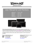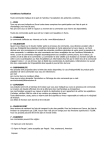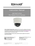
1
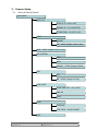
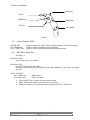
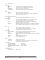
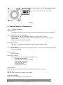
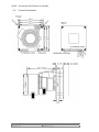
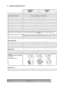
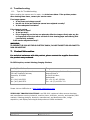
Wide Dynamic Range Pixim
Instruction Manual
20B40x Family
Prior to Using This Document: Videology reserves the right to modify the information
in this document as necessary and without notice. It is the user’s responsibility to be
certain they possess the most recent version of this document by going to
www.videologyinc.com or linking directly to: http://www.videology.com/xxxxx and
comparing revision letters, located in the document’s footer.
For technical assistance with this product, please contact the supplier from whom the
product was purchased.
Videology Imaging Solutions, Inc. USA
37M Lark Industrial Parkway
Greenville, RI 02828
Tel: 401-949-5332
Fax: 401-949-5276
Doc # INS 20B40x
Revision: B
Videology Imaging Solutions, B.V. Europe
Neutronenlaan 4
NL-5405 NH Uden, Netherlands
Tel: +31 (0) 413-256261
Fax: +31 (0) 413-251712
Issue Date: 12/19/2008
Page 1 of 10
Table Of Contents
Document History.............................................................................................. 3
General Information .......................................................................................... 3
2.1.
Safety Precautions ...................................................................................... 3
3. Camera Setup................................................................................................... 4
3.1.
Menu & Setting Details ................................................................................ 4
3.2.
Screen Display (OSD).................................................................................. 5
3.3.
OSD Menu Enter/Exit................................................................................... 5
3.4.
Main Menu ................................................................................................. 6
3. Camera Features & Dimensions ........................................................................... 7
4. .......................................................................................................................... 7
4.1.
Product Features......................................................................................... 7
4.2.
Product Dimensions..................................................................................... 8
5. Camera Specifications ........................................................................................ 9
6. Troubleshooting .............................................................................................. 10
6.1.
Tips for Troubleshooting ............................................................................ 10
7. Contact Information......................................................................................... 10
1.
2.
Doc # INS 20B40x
Revision: B
Issue Date: 12/19/2008
Page 2 of 10
1. Document History
Revision Issue Date Reason
Rev A
12-12-08
Initial release
CN#
08-0046
2. General Information
2.1.
•
•
•
•
•
•
•
•
Safety Precautions
Do not disassemble the unit
Do not put objects inside the unit
Make sure that no metal objects or flammable substances get inside the camera. It
could cause fire, short-circuits or damages.
Be careful when handling the unit
To prevent damage, do not drop the camera or subject it to strong shock or vibration
Install away from electric or magnetic fields
Protect from humidity and dust
Protect from high temperatures
Doc # INS 20B40x
Revision: B
Issue Date: 12/19/2008
Page 3 of 10
3.
Camera Setup
3.1.
Menu & Setting Details
MAIN MENU
SETUP ID
DISPLAY ID : ON or OFF
CAMERA ID : 12 CHARACTER
ID POSITION : UP-LEFT or UPLENS
MANUAL
DC : LEVEL (Range +10 to -40)
WDR : LEVEL (Range +20 to -20)
WB CONTROL
ATW
AWB
MANUAL : LEVEL (Range 2,500K
AGC
OFF
ON : LEVEL (Range 0 to 38)
LOW LIGHT
SLOW SHUTTER : AGC LEVEL
B&W SS
GAIN
SYNC
INTERNAL
LINE LOCK : PHASE ADJUST
EXIT
Doc # INS 20B40x
Revision: B
Issue Date: 12/19/2008
Page 4 of 10
Five key switchboard
RIGHT key
UP key
CENTER key
DOWN key
LEFT key
2nd VIDEO
Figure 1.
3.2.
Screen Display (OSD)
CENTER KEY
UP / DOWN KEY
LEFT / RIGHT KEY
3.3.
Used to access the menu mode, and also used to confirm the setting.
Used to choose the desired menu selection.
Used to choose the desired menu feature adjustment.
OSD Menu Enter/Exit
See figure 1
OSD Menu Enter
Push Center Key for 3 seconds
OSD Menu Exit
Press EXIT Menu from Main Menu
If pressing the Set Key for 3 seconds the Main Menu appears. In this case, just press
Set Key.
'SAVE' and 'QUIT'
Left or Right Key
Up or Down Key
Select Menu
Return to Menu
1. Press the SET key to access the main setup mode.
2. Select the desired feature using the UP or Down key.
3. Change the status of the selected feature using the LEFT or RIGHT key.
Doc # INS 20B40x
Revision: B
Issue Date: 12/19/2008
Page 5 of 10
3.4.
Main Menu
SETUP ID
DISPLAY ID
ON
OFF
CAMERA ID
ID POSITION
LENS
MANUAL
DC Iris
The ID name will be displayed in the monitor.
The name will not be displayed in the monitor.
You can write up to 12 characters.
Select the on screen position of the camera ID.
Select when using a manual lens.
You can control the brightness of the screen and adjust the
desired DC level from 10 to -40.
WDR (Wide Dynamic Range):
WDR
You can adjust the desired WDR level from 20 to -20.
WB CONTROL
ATW
AWB
MANUAL
AGC
ON
OFF
LOW LIGHT
SLOW SHUTTER
AGC
MAX FIELD
B&W SS
GAIN
SYNC
INTERNAL
LINE LOCK
(Auto Tracking White Balance) The camera automatically
controls the white balance in any environment.
(Auto White Balance) The white balance is automatically
adjusted in a specific environment.
Users can adjust the colors by adding or reducing the WB level.
You can adjust the desired WB level, from 2,500K to 9,500K.
Activate automatic gain control feature.
You can adjust the desired AGC level from 0 to 38dB.
Deactivate automatic gain control feature.
Control Image brightness by adjusting shutter speed.
Shutter speed setting (Range 28 to 48)
Shutter opens from a Min. of x2 to Max. x32 field accumulation
period.
Black and White Slow Shutter.
To get a brighter picture.
Internal synchronization
Phase adjustment may be necessary with multiple camera
installations to prevent picture roll.
EXIT MENU
EXIT NO CHANGES
SAVE NEW AND EXIT
RESTORE FACTORY SETTINGS
SW REV
PREVIOUS PAGE
PREVIOUS PAGE
Doc # INS 20B40x
Revision: B
No change
Save change
Factory default
Return page
Issue Date: 12/19/2008
Page 6 of 10
Functional Selection Switch (box model only)
You can choose NTSC or PAL via a switch
Figure 2.
4. Camera Features & Dimensions
4.1. Product Features
High Resolution
The camera has 480 lines of horizontal resolution and 460 lines of vertical resolution.
Superior Wide Dynamic Image Quality
The camera has very Wide Dynamic Range via a Pixim DSP Chip Set.
Film-like colors are described under various Light conditions even in high dynamic
range scenes
Dynamic Range is greater then 95dB.
Digital Pixel System
Each pixel is processed independently to get clear and usable images.
Various Lens Choices
It offers flexibility of the lens from board mount to C/CS mount lens with manual and
DC auto-iris control.
Power Source
DC 12V 300mA
OSD Control (Option)
Every function can be controlled by the OSD menu
- Automatic white balance
- Automatic gain control (max 38dB)
- Slow shutter, agc on/off
- Line lock phase control
- Lens type control
- Auto exposure control
Synchronization
Both Internal Synchronization and External Synchronization are provided.
Camera ID
The title that identifies this camera on a monitor.
NTSC/PAL Selectable
NTSC or PAL is selectable by simple Slide S/W
Doc # INS 20B40x
Revision: B
Issue Date: 12/19/2008
Page 7 of 10
RS232 - an optional RS232 board is available
4.2.
Product Dimensions
Doc # INS 20B40x
Revision: B
Issue Date: 12/19/2008
Page 8 of 10
5. Camera Specifications
20B40x
NTSC
Pick-up Device
Total of Pixels (H x V)
Horizontal Resolution
Scanning System
Synchronization
Video Output
Iris Control
White Balance
Gamma
Sensitivity
S/N Ratio
Dynamic Range
Shutter Speed
AGC Control
OSD Menu Control (Option)
Supplied Voltage
Power Consumption
Environmental
Operating Temperature
Storage Temperature
Operating Humidity
Storage Humidity
Mechanical
Dimensions (WxHxD)
Weight
Lens Mounts
Example:
Change 20B40x to 20B405
to select an
M-12 Board Mount.
Accessories
Optional
Doc # INS 20B40x
Revision: B
21B40x
PAL
1/3 inch CMOS (Dynamic Range Sensor)
742 x 552
480 Horizontal TV Lines (color)
525 lines interlaced
625 lines interlaced
Internal / External
1.0Vp-p/75 ohm Composite
DC Lens, Video Lens, Manual Lens
Auto/manual
0.45
0.6 Lux F1.2 Lens, 30 IRE
48dB or more
120dB(max), 102dB (typical)
1/60 - 1/100,000
1/50 - 1/100,000
0 - 34dB
4-directional Switch with a center Push TACTILE Switch &
RS232
DC 12V (8V - 18V),
Added board option & box camera allows AC 24V (20V - 30V)
Max 2.7W
-10° C ~ 50° C (14° F ~ 122° F)
-20° C ~ 70° C (-4° F ~ 158° F)
Under 90% Non-condensing
Under 95% Non-condensing
38mm x 38mm x 18mm (1.49” x 1.49” x 0.70”) without lens
30g (1.05 oz) without lens
Replace “X” in model number with desired lens mount option:
60ZRC01 – OSD control board
Issue Date: 12/19/2008
Page 9 of 10
6. Troubleshooting
6.1.
Tips for Troubleshooting
Before sending the camera out for repair, check
k the items below. If the problem persists
after checking these items, contact your service center.
If no image appears
• Is the power and voltage normal?
• Has the iris of the lens inside the camera been adjusted correctly?
• Is there adequate illumination?
If the
•
•
•
image is unclear
Is the lens in focus?
Is the lens dirty?
Dirt or fingerprints on the lens can adversely affect the images. Gently wipe any dirt
or fingerprints off the lens with a soft cloth or lens cleaning paper and cleaning fluid
(commercially available).
Is the monitor adjusted correctly?
WARNING:
TO PREVENT THE RISK OF FIRE OR ELECTRIC SHOCK, DO NOT EXPOSE THIS APPLIANCE TO
RAIN OR MOISTURE.
7.
Contact Information
For technical assistance with this product, please contact the supplier from whom
the product was purchased.
For OEM inquiries, contact Videology Imaging Solutions:
North / South America:
Europe:
Videology Imaging Solutions Inc.
37M Lark Industrial Parkway
Greenville, RI 02828
USA
Tel: (401) 949-5332
Fax: (401) 949-5276
Videology Imaging Solutions Europe
Neutronenlaan 4
NL-5405 NH Uden,
Netherlands
Tel: +31 (0) 413 256 261
Fax: +31 (0) 413 251 712
Please visit our WEB-site at: http://www.videologyinc.com/
VIDEOLOGY IMAGING SOLUTIONS is an ISO 9001 registered video camera developer
and manufacturer serving industrial, machine vision, biometric, security, and specialty OEM
markets. Videology designs, develops, manufactures, and distributes video, image
acquisition, and display technologies and products to OEMs worldwide.
Doc # INS 20B40x
Revision: B
Issue Date: 12/19/2008
Page 10 of 10