1
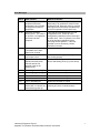
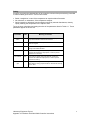
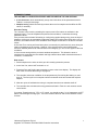
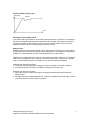
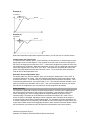
Appendix A Eurotherm Controller Instructions Description of Controls General The control panel is fitted with two controls: an ON/OFF SWITCH, and a TEMPERATURE CONTROLLER. On/Off Switch The On/Off switch isolates mains power to the temperature controller and to the solid state relay. If access to electrical connections inside the equipment is required, ensure that the electrical power is switched off where the equipment is connected to the main supply. Temperature Controller The Eurotherm microprocessor temperature controller has the facility to program a ramp in °C/seconds/minutes/hours. Indicator and Button Functions The Eurotherm controller has the following buttons and indicators: Indicator or button Name Function OP1 Output 1 When lit, this indicates that the element output is on. OP2 Output 2 When lit, this indicates that an alarm condition exists. Page button Press to select a new list of parameters. Scroll button Press to select a new parameter in a list. Down button Press and release to view the setpoint or a selected parameter. Keep pressed to decrease the value. Up button Press and release to view the setpoint or a selected parameter. Keep pressed to increase the value Laboratory Equipment Pty Ltd Appendix A. Eurotherm 3216/2416/2404 Controller Instructions 1 Display The display normally indicates actual temp or parameter mnemonic and it will indicate setpoint temp or parameter value when up or down keys are pressed Changing the Setpoint, Ramp Rate and Hold Timer The temperature controller's normal display shows the actual temperature. The setpoint can be changed using the /\ or \/ buttons and the equipment will hold at that temperature. Pressing the scroll button once changes the display to oP or % output power. Pressing the scroll button again changes the display to Sprr or setpoint ramp rate and can be set to either OFF or from 1 to 60°C/min Pressing the scroll button again changes the display to dwEll or setpoint hold time and can be set to either off or 999.9 minutes. Pressing the scroll button again changes the display to StAt or program status and can be set to on or off. In the on status, the dwell timer will function, in the off status the controller ignores the dwell setting. The status will change to off automatically when the dwell period ends. Auto-tune List Pressing the Page key once changes the display to the Auto-tune list Atun. Pressing the Scroll key changes the display to tune or tune function selection. Auto-tune may now be selected using the /\ or \/ buttons. PID List Pressing the Page key again changes the display to the PID List PID. Pressing the Scroll key changes the display to Pb, ti, td, Hcb, and Lcb. The values for these may be accessed and changed using the /\ or \/ buttons. A full description of their meanings is in the Tuning section. Operating the Equipment When the equipment is first turned on the controller will carry out self checks and then start controlling at the setpoint value. Set the parameters detailed in the manual. To reset the controller after dwell end (End) or other alarm press the PAGE and SCROLL keys simultaneously. If a ramp dwell program is to be run again set status back to on. When running the equipment at a new temperature that varies more than about 25% from the previous temperature it may be necessary to run the auto-tuning program to reset the PID parameters. The equipment will overshoot the setpoint when running the auto-tune program especially at low temperatures. Laboratory Equipment Pty Ltd Appendix A. Eurotherm 3216/2416/2404 Controller Instructions 2 Error Messages Alarm What it means What to do about it FSH1 Full Scale High Alarm: The equipment measured temperature has exceeded the equipment maximum temperature. This fault may be caused by a faulty solid state relay or by exothermic reaction of the equipment load. Reset the alarm by pressing the Page and Scroll buttons simultaneously and check operation of solid state relay. EE.Er Electrically Erasable Memory Error: The value of an operator or configuration parameter has been corrupted. This fault will automatically take you into configuration level. Check all of the configuration parameters before returning to operator level. Once in operator level, check all of the operator parameters before resuming normal operation. If the fault persists or occurs frequently, contact Eurotherm Controls. S.br Sensor Break: Input sensor is unreliable or the input signal is out of range. Check that the sensor is correctly connected. L.br Loop Break: The feedback loop is open circuit. Check that the heating and cooling circuits are working properly. Ld.f Heater circuit fault: Indication that the power controller device has detected a fault in the heating circuit. Check the functioning of the power control device and heating circuit.(e.g. fuse failure). LLLL Out of range low reading Check the value of the input HHHH Out of range high reading Check the value of the input Err1 Error 1: ROM self-test fail Return the controller for repair Err2 Error 2: RAM self-test fail Return the controller for repair Err3 Error 3: Watchdog fail Return the controller for repair Err4 Error 4: Keyboard failure Stuck button or a button was pressed during power up. Switch the power off and then on without touching any of the controller buttons. Laboratory Equipment Pty Ltd Appendix A. Eurotherm 3216/2416/2404 Controller Instructions 3 Tuning In tuning, you match the characteristics of the controller to those of the process being controlled in order to obtain good control. Good control means: Stable, ‘straight-line’ control of the temperature at setpoint without fluctuation No overshoot, or undershoot, of the temperature setpoint Quick response to deviations from the setpoint caused by external disturbances, thereby rapidly restoring the temperature to the setpoint value. Tuning involves calculating and setting the value of the parameters listed in Table 4-1. These parameters appear in the ‘Pid’ list. Parameter Code Meaning or Function Proportional band Pb The bandwidth, in display units, over which the output power is proportioned between minimum and maximum. Integral time ti Determines the time taken by the controller to remove steadystate error signals. Derivative time td Determines how strongly the controller will react to the rate-ofchange of the measured value. High Cutback Hcb The number of display units, above setpoint, at which the controller will increase the output power, in order to prevent undershoot on cool down. Low cutback Lcb The number of display units, below setpoint, at which the controller will cutback the output power, in order to prevent overshoot on heat up. Relative cool gain rEL Only present if cooling has been configured and a module is fitted. Sets the cooling proportional band:- divide the Pb value by the rEL value. Table 4-1 Tuning parameters Laboratory Equipment Pty Ltd Appendix A. Eurotherm 3216/2416/2404 Controller Instructions 4 AUTOMATIC TUNING TWO AUTOMATIC TUNING PROCEDURES ARE PROVIDED IN THE 2408 AND 2404: A one-shot tuner, which automatically sets up the initial values of the parameters listed in Table 4-1 on the previous page. Adaptive tuning, which continuously monitors the error from setpoint and modifies the PID values, if necessary. One-shot Tuning The ‘one-shot’ tuner works by switching the output on and off to induce an oscillation in the measured value. From the amplitude and period of the oscillation, it calculates the tuning parameter values. If the process cannot tolerate full heating or cooling being applied during tuning, then the level of heating or cooling can be restricted by setting the heating and cooling power limits in the ‘oP’ list. However, the measured value must oscillate to some degree for the tuner to be able to calculate values. A One-shot Tune can be performed at any time, but normally it is performed only once during the initial commissioning of the process. However, if the process under control subsequently becomes unstable (because its characteristics have changed), you can re-tune again for the new conditions. It is best to start tuning with the process at ambient temperature. This allows the tuner to calculate more accurately the low cutback and high cutback values which restrict the amount of overshoot, or undershoot. How to tune 1. Set the setpoint to the value at which you will normally operate the process. 2. In the ‘Atun’ list, select ‘tunE’ and set it to ‘on’. 3. Press the Page and Scroll buttons together to return to the Home display. The display will flash ‘tunE’ to indicate that tuning is in progress. 4. The controller induces an oscillation in the temperature by first turning the heating on, and then off. The first cycle is not complete until the measured value has reached the required setpoint. 5. After two cycles of oscillation the tuning is completed and the tuner switches itself off. 6. The controller then calculates the tuning parameters listed in Table 4-1 and resumes normal control action. If you want ‘Proportional only’, ‘PD’, or ‘PI’ control, you should set the ‘ti’ or ‘td’ parameters to OFF before commencing the tuning cycle. The tuner will leave them off and will not calculate a value for them. Laboratory Equipment Pty Ltd Appendix A. Eurotherm 3216/2416/2404 Controller Instructions 5 Typical automatic tuning cycle Temperature Setpoint Time Calculation of the cutback values Low cutback and High cutback are a value that restrict the amount of overshoot, or undershoot, that occurs during large step changes in temperature (for example, under start-up conditions). If either low cutback, or high cutback, is set to ‘Auto’ the values are fixed at three times the proportional band, and are not changed during automatic tuning. Adaptive tune Adaptive tuning is a background algorithm, which continuously monitors the error from setpoint and analyses the control response during process disturbances. If the algorithm recognises an oscillatory, or under-damped, response it recalculates the Pb, ti and td values. Adaptive tune is triggered whenever the error from setpoint exceeds a trigger level. This trigger level is set in the parameter ‘drA.t’, which is found in the Autotune list. The value is in display units. It is automatically set by the controller, but can also be manually re-adjusted. Adaptive tune should be used with: 1. Processes whose characteristics change as a result of changes in the load, or setpoint. 2. Processes that cannot tolerate the oscillation induced by a One-shot tune. Adaptive tune should not be used: 1. Where the process is subjected to regular external disturbances that could mislead the adaptive tuner. 2. On highly interactive multiloop applications. However, moderately interactive loops, such as multi-zone extruders, should not give a problem. Laboratory Equipment Pty Ltd Appendix A. Eurotherm 3216/2416/2404 Controller Instructions 6 MANUAL TUNING If for any reason automatic tuning gives unsatisfactory results, you can tune the controller manually. There are a number of standard methods for manual tuning. The one described here is the Ziegler-Nichols method. With the process at its normal running temperature: 1. Set the Integral Time ‘ti’ and the Derivative Time ‘td’ to OFF. 2. Set High Cutback and Low Cutback, ‘Hcb’ and ‘Lcb’, to ‘Auto’. 3. Ignore the fact that the temperature may not settle precisely at the setpoint. If the temperature is stable, reduce the proportional band ‘Pb’ so that the temperature just starts to oscillate. If the temperature is already oscillating, increase the proportional band until it just stops oscillating. Allow enough time between each adjustment for the loop to stabilise. Make a note of the proportional band value ‘B’ and the period of oscillation ‘T’. 4. Set the Pb, ti, td parameter values according to the calculations given in Table 4-2. Type of control Proportional band ‘Pb’ Integral time ‘ti’ Derivative time ‘td’ Proportional only 2xB OFF OFF P + I control 2.2xB 0.8xT OFF P + I + D control 1.7xB 0.5xT 0.12xT Table 4-2 Tuning values Setting the cutback values The above procedure sets up the parameters for optimum steady state control. If unacceptable levels of overshoot or undershoot occur during start-up, or for large step changes in temperature, then manually set the cutback parameters ‘Lcb’ and ‘Hcb’. Proceed as follows: 1. Set the low and high cutback values to three proportional bandwidths (that is to say, Lcb = Hcb = 3 x Pb). 2. Note the level of overshoot, or undershoot, that occurs for large temperature changes (see the diagrams below). In example (a) increase ‘Lcb’ by the overshoot value. In example (b) reduce ‘Lcb’ by the undershoot value. Laboratory Equipment Pty Ltd Appendix A. Eurotherm 3216/2416/2404 Controller Instructions 7 Example (a) Temperature Overshoot Setpoint Example (b) Temperature Setpoint Undershoot Time Where the temperature approaches setpoint from above, you can set ‘Hcb’ in a similar manner. Integral action and manual reset In a full three-term controller (that is, a PID controller), the integral term ‘ti’ automatically removes steady state errors from the setpoint. If the controller is set up to work in two-term mode (that is, PD mode), the integral term will be set to ‘OFF’. Under these conditions the measured value may not settle precisely at setpoint. When the integral term is set to ‘OFF’ the parameter manual reset (code ‘rES’) appears in the ‘Pid LiSt’ in ‘FuLL’ level. This parameter represents the value of the power output that will be delivered when the error is zero. You must set this value manually in order to remove the steady state error. Automatic droop compensation (Adc) The steady state error from the setpoint, which occurs when the integral term is set to ‘OFF’ is sometimes referred to as ‘droop’. ‘Adc’ automatically calculates the manual reset value in order to remove this droop. To use this facility, you must first allow the temperature to stabilise. Then, in the autotune parameter list, you must set ‘Adc’ to ‘on’. The controller will then calculate a new value for manual reset, and switch ‘Adc’ to ‘OFF’. ‘Adc’ can be repeated as often as you require, but between each adjustment you must allow time for the temperature to stabilise. Safety Controller The controller is fitted with an inbuilt over heat safety protection. It must be set to slightly above the desired setpoint temperature and will prevent overheating. It will maintain the Alarm Set Value. Change the AL1 value to slightly above the setpoint temperature as set out in the instruction page. The Alarm will be activated if the incubator exceeds the AL1 value or if the sensor is broken or damaged. Adjusting the Alarm Hysterisis value will cause the incubator to cool down by that value before it begins heating again. For example if the Alarm Hysterisis is set to 100 the incubator must cool down by 100°c below AL1 before it will begin to reheat. Where you require the incubator to switch off completely should an alarm condition result then please contact the manufacturer to purchase the OST100 manual overtemperature reset control system. Laboratory Equipment Pty Ltd Appendix A. Eurotherm 3216/2416/2404 Controller Instructions 8