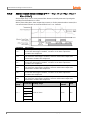
1
USER MANUAL
© Copyright Reserved Autonics Co., Ltd.
iii
iv
© Copyright Reserved Autonics Co., Ltd.
Preface
Preface
Thank you for purchasing an Autonics product.
Please familiarize yourself with the information contained in the Safety Precautions section
before using this product.
This user manual contains information about the product and its proper use, and should be kept
in a place where it will be easy to access.
© Copyright Reserved Autonics Co., Ltd.
v
User Manual Guide
User Manual Guide
vi
Please familiarize yourself with the information in this manual before using the product.
This manual provides detailed information on the product's features. It does not offer any
guarantee concerning matters beyond the scope of this manual.
This manual may not be edited or reproduced in either part or whole without permission.
A user manual is not provided as part of the product package.
Visit our web site (www.autonics.com) to download a copy.
The manual's content may vary depending on changes to the product's software and other
unforeseen developments within Autonics, and is subject to change without prior notice.
Upgrade notice is provided through out homepage.
We contrived to describe this manual more easily and correctly. However, if there are any
corrections or questions, please notify us these on our homepage.
© Copyright Reserved Autonics Co., Ltd.
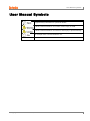
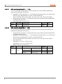
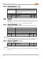
User Manual Symbols
User Manual Symbols
Symbol
Description
Supplementary information for a particular feature.
Failure to follow instructions can result in serious injury or death.
Failure to follow instructions can lead to a minor injury or product damage.
An example of the concerned feature's use.
※1
Annotation mark.
© Copyright Reserved Autonics Co., Ltd.
vii
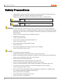
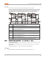
Safety Precautions
Safety Precautions
Following these safety precautions will ensure the safe and proper use of the product and
help prevent accidents, as well as minimizing possible hazards.
Safety precautions are categorized as Warnings and Cautions, as defined below:
Warning
Failure to follow the instructions may lead to a serious injury
or accident.
Caution
Failure to follow the instructions may lead to a minor injury
or accident.
In case of using this unit with machinery (Ex: nuclear power control, medical equipment,
ship, vehicle, train, airplane, combustion apparatus, safety device, crime/disaster prevention
equipment, etc) which may cause damages to human life or property, it is required to install
fail-safe device.
It may cause a fire, human injury or damage to property.
Install the unit on a panel.
It may cause electric shock.
Do not connect, inspect or repair when power is on.
It may cause electric shock.
Wire properly after checking terminal number.
It may cause a fire.
Do not disassemble the case. Please contact us if it is required.
It may cause electric shock or a fire.
This unit shall not be used outdoors.
It might shorten the life cycle of the product or cause electric shock.
When connecting wire, AWG 20(0.50mm²) should be used and screw bolt on terminal block.
It may cause a malfunction or fire due to contact failure.
Please observe the rated specifications.
It might shorten the life cycle of the product and cause a fire.
Do not use beyond of the rated switching capacity of relay contact.
It may cause insulation failure, contact melt, contact failure, relay broken and fire etc.
In cleaning unit, do not use water or an oil-based detergent and use dry towels.
It may cause electric shock or a fire.
Do not use this unit in place where there are flammable or explosive gas, humidity, direct
ray of the light, radiant heat, vibration and impact etc.
It may cause a fire or an explosion.
Do not inflow dust or wire dregs into the unit.
It may cause a fire or a malfunction.
viii
© Copyright Reserved Autonics Co., Ltd.
Safety Precautions
Please wire properly after checking the terminal polarity when connecting temperature
sensor.
It may cause a fire or an explosion.
© Copyright Reserved Autonics Co., Ltd.
ix
Safety Precautions
x
© Copyright Reserved Autonics Co., Ltd.
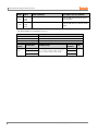
Table of Contents
Table of Contents
Preface v
User Manual Guide ................................................................................................................ vi
User Manual Symbols ........................................................................................................... vii
Safety Precautions ............................................................................................................... viii
Table of Contents ................................................................................................................... xi
1
Product Introduction................................................................................. 15
1.1
Features .................................................................................................................. 15
1.2
Components and Accessories ................................................................................. 16
1.3
Ordering information ............................................................................................... 20
1.4
Parts descriptions .................................................................................................... 22
2
Specifications ............................................................................................ 25
3
Dimensions................................................................................................ 27
4
Connections .............................................................................................. 33
4.1
Precautions for wiring .............................................................................................. 35
4.1.1
4.1.2
5
Preparation and Startup ........................................................................... 37
5.1
Initial display when power ON ................................................................................. 37
5.2
Basic controls .......................................................................................................... 38
5.2.1
5.2.2
5.2.3
Parameter setting sequence ...................................................................... 38
Set value (SV) setting ................................................................................ 38
MV monitoring and manual control ............................................................ 39
5.3
Parameter group ..................................................................................................... 42
5.4
Parameter groups .................................................................................................... 45
5.4.1
5.4.2
5.4.3
5.4.4
5.4.5
6
Sensor connection ..................................................................................... 35
Communication connection ........................................................................ 35
Parameter 1 group [PAR1] ......................................................................... 45
Parameter 2 group [PAR2] ......................................................................... 46
Parameter 3 group [PAR3] ......................................................................... 48
Parameter 4 group [PAR4] ......................................................................... 50
Parameter 5 group [PAR5] ......................................................................... 53
Parameter Settings and Functions .......................................................... 55
6.1
Input ........................................................................................................................ 55
6.1.1
6.1.2
6.1.3
6.1.4
6.1.5
6.1.6
6.1.7
6.2
Input types and temperature ranges .......................................................... 55
Input type [PAR3 → IN-T].......................................................................... 56
Sensor temperature unit [PAR3 → UNIT]................................................... 56
Analog input/scale value ............................................................................ 57
Input correction [PAR3 → IN-B]................................................................. 59
Input digital filter [PAR3 → MAvF] ............................................................... 59
High/Low-limit value of setting value(SV) [PAR3 → H-SV/ L-SV] ............. 60
Control output .......................................................................................................... 61
6.2.1
Control output mode [PAR3 → O-FT] ......................................................... 61
© Copyright Reserved Autonics Co., Ltd.
xi
Table of Contents
6.2.2
6.2.3
6.2.4
6.2.5
6.3
Temperature control ................................................................................................ 73
6.3.1
6.3.2
6.3.3
6.3.4
6.4
MV High/Low-limit value settings [PAR2 → H-MV / L-MV] ......................... 66
Ramp settings [PAR2 → RAMU/ RAMD/ rUNT] ............................................ 67
Auto/Manual control settings ...................................................................... 69
Output settings ........................................................................................... 72
Temperature control mode [PAR3 → C-MD] ............................................... 73
ON/OFF control [PAR3 → C-MD → ONOF] .................................................. 74
PID control [PAR3 → C-MD → PID] ............................................................ 75
Auto-tuning ................................................................................................. 77
Alarm output ............................................................................................................ 79
Alarm operation [PAR4 → AL-1/AL-2/AL-3]............................................ 79
Alarm output options [PAR4 → AL!T/AL@T] .............................................. 81
Alarm SV settings [PAR1 → AL!L/AL!H/AL@L/AL@H/AL#L/AL#H] .......... 82
Alarm output hysteresis [PAR4 → A!HY/A@HY/A#HY] ............................... 82
Alarm N.O./N.C. [PAR4 → A!N/A@N/A#N] .................................................. 83
Alarm output delay settings
[PAR4 → A!ON / A!OF/ A@ON / A@OF/ A#ON / A#OF] .............................. 84
6.4.7 Loop break alarm(LBA) [PAR4 → AL-1/AL-2/AL-3 → LBA] .................... 85
6.4.8 Sensor break alarm [PAR4 → AL-1/AL-2/AL-3 → SBA] .......................... 87
6.4.9 Heater burnout alarm [PAR4 → AL-1/AL-2/AL-3 → HBA] ....................... 88
6.4.10 Alarm output deactivation [PAR5 → DI-K→ AlRE] .................................... 89
6.4.11 Alarm output examples............................................................................... 90
6.4.1
6.4.2
6.4.3
6.4.4
6.4.5
6.4.6
6.5
Analog transmission ................................................................................................ 93
6.5.1
6.5.2
6.6
Communication settings .......................................................................................... 95
6.6.1
6.6.2
6.6.3
6.6.4
6.6.5
6.6.6
6.6.7
6.7
xii
Unit address settings [PAR4 → ADRS] ........................................................ 95
BPS (bits per second) settings [PAR4 → BPS] ........................................... 95
Communication parity bit [PAR4 → PRTY] .................................................. 96
Communication stop bit settings [PAR4 → STP]......................................... 96
Response wait time settings [PAR4→ RSwT].............................................. 96
Enable/Disable communication write[PAR4→ COMW] ................................. 97
USB to Serial communication connection .................................................. 97
Additional features ................................................................................................... 98
6.7.1
6.7.2
6.7.3
6.7.4
6.7.5
6.7.6
6.7.7
6.7.8
6.7.9
7
Analog transmission output value settings [PAR4 → AoM1/ AoM2]............ 93
Transmission output high/low-limit value settings
[PAR4 → FsL1/ FsH1→ FsL2/ FsH2] ...................................................... 93
Monitoring ................................................................................................... 98
RUN/STOP [PAR1 → R-S] ......................................................................... 99
Multi SV .................................................................................................... 100
Digital input ............................................................................................... 101
Error.......................................................................................................... 103
User level setting [PAR5 → USER] ............................................................ 104
Lock settings ............................................................................................ 104
Parameter initialization[INIT] .................................................................. 105
Password settings [PAR5 → PWD]............................................................. 105
Setting group parameter description ....................................................107
7.1
Setting group [ SV ] ............................................................................................... 107
7.2
MV monitoring/manual control setting group [ MV ] ............................................... 107
7.3
Parameter 1 setting group [ PAR1 ]....................................................................... 108
© Copyright Reserved Autonics Co., Ltd.
Table of Contents
8
7.4
Parameter 2 setting group [PAR2 ] ....................................................................... 109
7.5
Parameter 3 setting group [ PAR3 ] ....................................................................... 111
7.6
Parameter 4 setting group [ PAR4 ] ...................................................................... 113
7.7
Parameter 5 setting group [ PAR5 ] ...................................................................... 115
7.8
Password entry parameter .................................................................................... 116
7.9
Parameter change reset parameters .................................................................... 116
DAQMaster .............................................................................................. 117
8.1
Overview ............................................................................................................... 117
8.2
Major features ....................................................................................................... 118
8.3
Special feature for TK Series ................................................................................ 119
8.3.1
8.3.2
Parameter mask ....................................................................................... 119
User parameter group [PARU] .................................................................. 121
© Copyright Reserved Autonics Co., Ltd.
xiii
Table of Contents
xiv
© Copyright Reserved Autonics Co., Ltd.
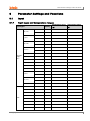
1 Product Introduction
1
Product Introduction
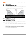
1.1
Features
TK Series – standard PID temperature controller – realizes more powerful control with super
high-speed sampling cycles of 50 ms and ±0.3% display accuracy. It supports diverse control
modes including heating & cooling simultaneous control, and automatic/manual control and
communication functions. In addition, TK Series covers all necessary features for high
performance temperature controllers – that is, diverse input sensor support, multi SV setting,
SSR drive output + current output, high resolution display and compact size.
Improves convenience for parameter setting (using DAQMaster)
Parameter mask
To hide parameters which are not unnecessary or not used frequently
User parameter group
To group parameters which are used frequently as one group for more convenient
setting
Super high-speed sampling cycle (10 times faster compared to existing models);
50 ms sampling cycle and ±0.3% display accuracy
Improved visibility with wide display and high luminance LED
High performance control with heating & cooling control and automatic/manual control
modes
Communication function supported: RS485 (Modbus RTU type)
PC parameter setting (USB and RS 485 communication)
Free download integrated device management program (DAQMaster)
※Communication converter, sold separately
SCM-US(USB to Serial converter), SCM-38I(RS232C to RS485 converter),
SCM-US48I(USB to RS485 converter)
SSR drive output/current output selection function
ON/OFF, Cycle, Phase control by SSRP function
Heater burn-out alarm (CT input) (except TK4SP)
※CT, sold separately: CSTC-E80LN, CSTC-E200LN
Multi SV setting function (Max. 4 ) – selectable via digital input terminals
Space saving mounting possible with compact design ; downsized by 38% (depth-based)
Multi-input/multi-range
© Copyright Reserved Autonics Co., Ltd.
15
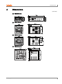
1 Product Introduction
1.2
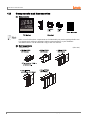
Components and Accessories
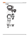
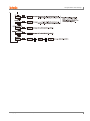
(1) Components
Make sure all of the above components are included with your product package before use.
If a component is missing or damaged, please contact Autonics or your distributor.
Visit www.autonics.com to download a copy of the user manual.
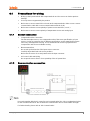
(2) Sold separately
16
Terminal cover
(unit: mm)
© Copyright Reserved Autonics Co., Ltd.
1 Product Introduction
Socket (for TK4SP)
PG-11
(unit: mm)
PS-11
Communication converter
SCM-38I
(RS232C to RS485 converter)
© Copyright Reserved Autonics Co., Ltd.
SCM-US48I
(USB to RS485 converter)
SCM-US
(USB to Serial converter)
17
1 Product Introduction
Current transformer(CT)
CSTC-E80LN
Max. load current: 80A(50/60Hz)
※Max. load current for TK4 Series is 50A.
Current ratio: 1/1000
Wire wounded resistance: 31Ω ±10%
(unit: mm)
18
© Copyright Reserved Autonics Co., Ltd.
1 Product Introduction
CSTC-E200LN
Max. load current: 200A(50/60Hz)
※Max. load current for TK4 Series is 50A.
Current ratio: 1/1000
Wire wounded resistance: 20Ω±10%
(unit: mm)
Images of components and accessories may differ from actual products.
For detailed information about any of the above products, please refer to the concerned
product's user manual.
Visit our website (www.autonics.com) to download copies of the user manuals.
For using CT, do not supply first part current when opening CT output.
It occurs high voltage at CT output part.
Using current of above two CTs are same as 50A. But be sure that inner hole sizes are different.
Select it properly for the environment.
© Copyright Reserved Autonics Co., Ltd.
19
1 Product Introduction
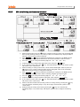
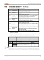
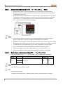
1.3
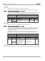
Ordering information
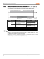
TK
4
S -
1
4
R
R
①
②
③
④
⑤
⑥
⑦
Category
Description
① Item
TK
Temperature/Process controller
② Digit
4
9999(4digit)
N
DIN W48×H24mm
SP
DIN W48×H48mm (11 pin plug type※7)
S
DIN W48×H48mm (terminal block type)
M
DIN W72×H72mm
W
DIN W96×H48mm
H
DIN W48×H96mm
L
DIN W96×H96mm
③ Size
Standard: Alarm output 1+CT input※4,
1
N
Heating&Cooling: Alarm output 2※5
2
Standard: Alarm output 1+Alarm output 2
D
Standard: Alarm output 1+Digital input(DI-1, DI-2)
Standard: Alarm output 1+Digital input, Heating&Cooling:
Trans. output
Standard: Alarm output 1+RS485com. output
Heating&Cooling: RS485com. output
R
T
④ Input/Output
Option※1
S
P
S
M
W
H
L
⑤ Power Supply
⑥ OUT1 Control
Output※2
1
Alarm output 1
1
Alarm output 1
2
Alarm output 1+Alarm output 2
R
Alarm output 1+Trans. output
T
Alarm output 1+RS485com. output
A
Alarm output 1+Alarm output 2+Trans. output
B
Alarm output 1+Alarm output 2+
RS485 com. output
D
Alarm output 1+Alarm output 2+Digital input(DI-1, DI-2)※6
4
100 to 240VAC, 50/60Hz
R
Relay output
S
SSR drive output(standard ON/OFF, cycle, phase control)
C
Current output + SSR drive output
None
Standard
N
Heating
&
Cooling
R Relay output
⑦ OUT2 Control
Output
20
※3
※Select in case of standard control (heating or cooling)
C Current output + SSR drive output
© Copyright Reserved Autonics Co., Ltd.
1 Product Introduction
※1. In case of TK4N/SP Series, option control output selection and digital input will be
limited due to number of terminals.
※2. “S” represents SSR drive output support models which SSRP function (standard
ON/OFF, cycle, phase)control are available. “C” represents selectable current and
SSR drive output support models.
※3. Select “R” or “C” type in case of using heating & cooling control. “N” type in case fo
using standard control.
※4. The CT input model of TK4N is selectable only for standard model which has alarm 1.
※5. The Heaing & Cooling model of TK4N-1□□□ has only alarm output 2.
※6. Only for TK4S-D□□□, OUT2 output terminal is used as DI-2 input terminal.
※7. 11Pin socket(PG-11, PS-11): Sold separately
CT (Current Transformer) input is supported by all models.
However, TK4SP (11 pin plug type) does not support CT input due to its limited number of
terminal blocks.
© Copyright Reserved Autonics Co., Ltd.
21
1 Product Introduction
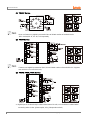
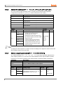
1.4
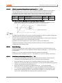
Parts descriptions
①
②
③
④
⑤
⑥
22
Measured value(PV) display part:
RUN mode: It displays currently measured value (PV).
Setting mode: It displays the parameter.
Set value (SV) display part:
RUN mode: It displays the set value (SV).
Setting mode: It displays the set value of the parameter.
Unit(℃/℉/%) indicator: It displays the unit set at display unit [UNT] in parameter 3 group.
(TK4N Seires does not support ‘%’ unit.)
Manual control indicator: It turns ON during manual controlling.
Multi SV indicator: One of SV1 to 3 indicator will be ON in case of selecting multi SV
function.
Auto tuning indicator: It flashes by 1 sec. when executing auto tuning.
© Copyright Reserved Autonics Co., Ltd.
1 Product Introduction
⑦
Alarm output (AL1, AL2) indicator: It turns ON when the alarm output is ON.
⑧
Control output (OUT1, OUT2) indicator: It turns ON when the control output is ON.
During cycle/phase controlling in SSRP function model (TK4□-□4S□)type, when MV is
over 5.0%, it turns ON.
※ To use current ouput, when MV is 0.0% in manual control, it turns OFF. Otherwise, it
always turns ON. When MV is over 3.0% in auto control, it turns ON and when MV is
below 2.0%, it turns OFF.
key: It is used when switching auto control to manual control.
⑨
⑩
⑪
⑫
⑬
⑭
※ TK4N/S/SP do not have the
key. The
key operates switching
simultaneously.
key: It is used when entering parameter group, returning to RUN mode, moving
parameter, saving the set value.
key: It is used when entering the set value changing mode and moving or
changing up/down digit.
Digital input key: When pressing the
keys for 3 sec. at the same time, it operates
the function (RUN/STOP, alarm clear,auto tuning) set at digital input key [DI-K] in
parameter 5 group.
PC loader port: It is the PC loader port for serial communication to set parameter and
monitoring by DAQMaster installed in PC. Use this for connecting SCM-US(USB to Serial
converter, sold separately).
Input selection switch: Used when switching sensor (TC, RTD) input ↔ analog input(mV,
V, mA) (only the previous models)
7-Segment Display Characters
A
B
C
D
E
F
G
H
I
J
K
L
M
A
B
C
D
E
F
G
H
I
J
K
L
M
N
O
P
Q
R
S
T
U
V
W
X
Y
Z
N
O
P
Q
R
S
T
U
V
W
X
Y
Z
0
1
2
3
4
5
6
7
8
9
0
`
/
0
1
2
3
4
5
6
7
8
9
0
-1
/
© Copyright Reserved Autonics Co., Ltd.
23
1 Product Introduction
24
© Copyright Reserved Autonics Co., Ltd.
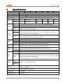
2 Specifications
2
Specifications
Series
Power supply
TK4N
TK4SP
100-240VAC, 50/60Hz
Allowable voltage range
±10% of rated voltage
Power consumption
Max. 6VA
Display method
7 segment (PV: red, SV: green), all other displays (green, orange, red) LED
Character
size
Input type
TK4S
TK4M
TK4W
TK4H
TK4L
Max. 8VA
PV(W×H)
4.5 × 7.2
mm
7.0×14.0mm
9.5×20.0
mm
8.5×17.0
mm
7.0×14.6
mm
11.0×22.0
mm
SV(W×H)
3.5 × 5.8
mm
5.0×10.0mm
7.5×15.0
mm
6.0×12.0
mm
6.0×12.0
mm
7.0×14.0
mm
RTD
JPt 100Ω, DPt 100Ω, DPt 50Ω, Cu 100Ω, Cu 50Ω, and Nikel 120Ω (6 types)
TC
K, J, E, T, L, N, U, R, S, B, C, G, and PLII (13 types)
Analog
Voltage: 0-100mV, 0-5V, 1-5V, and 0-10V (4 types)
Current: 0-20mA and 4-20mA (2 types)
RTD
At room temperature (23℃ ± 5℃): (PV ± 0.3% or ± 1℃, select the higher one) ± 1 digit※
1
Out of room temperature ranges: (PV ± 0.5% or ± 2℃, select the higher one) ± 1 digit
Display
accuracy
TC
Analog
In case of TK4SP Series, ±1℃ will be added.
At room temperature (23℃ ± 5℃): ± 0.3% F.S. ± 1 digit
Out of room temperature ranges: ± 0.5% F.S. ± 1 digit
Control
output
Alarm
output
Option
output
Option
input
CT Input
± 5% F.S. ± 1 digit
Relay
OUT1, OUT2: 250VAC 3A 1a
SSR
Max.11VDC ± 2V 20mA
Current
DC4-20mA or DC0-20mA selectable (resistance load max. 500Ω)
Relay
AL1, AL2 Relay: 250VAC 3A 1a
(TK4N AL2: 250VAC 0.5A 1a (max. 125VA), TK4SP has only AL1)
Transmissi
on output
DC4-20mA (resistance load max. 500Ω, output accuracy: ±0.3% F.S)
Comm.
RS485 Communication Output (Modbus RTU)
CT
0.0-50.0A (primary heater current reading range) ※CT Ratio is 1/1000 (except TK4SP)
Contact input - ON: Max. 2kΩ, OFF: Min. 90kΩ
Digital
input
Non-Contact input - ON: Residual voltage max. 1.0V, OFF: Leakage current min. 0.1mA
Leakage current: Approx. 0.5mA per input
※TK4S/M-1EA(TK4S-D□□□-2EA, TK4SP-None), TK4N/H/W/L-2EA(except TK4SP)
Control
type
Heating &
cooling
Heating or
Cooling
Hysteresis
ON/OFF, P, PI, PD, PID control mode
RTD/ Thermocouples: 1 to 100℃/℉ (0.1 to 100.0℃/℉) variable
Analog: 1 to 100 digit
Proportional band (P)
0.1 to 999.9℃/℉ (0.1 to 999.9%)
Integral time (I)
0 to 9999sec.
Derivative time (D)
0 to 9999sec.
© Copyright Reserved Autonics Co., Ltd.
25
2 Specifications
Control period (T)
Relay output, SSR drive output: 0.1 to 120.0 sec.
Current output+SSR drive output: 1.0 to 120.0 sec.
Manual reset value
0.0 to 100.0%
Sampling period
50 ms
Dielectric strength
2,000 VAC 50/60 Hz for 1 min. (between power source terminal and input terminal)
Vibration resistance
0.75mm amplitude at frequency of 5 to 55 Hz (for 1 min.) in each of X, Y, Z directions for
2 hours
Relay
life
cycle
Mechanical
OUT1/OUT2: Min. 5,000,000 operations
AL1/2: Min. 20,000,000 operations (TK4H/W/L: Min. 5,000,000 operations)
Electrical
OUT1/OUT2: Min. 200,000 operations
AL1/2: Min. 100,000 operations(TK4H/W/L: Min. 200,000 operations)
Insulation resistance
Min. 100M• (at 500VDC megger)
Noise resistance
Square shaped noise by noise simulator (pulse width 1 ㎲) ±2 kV R-phase, S-phase
Memory retention
Approx. 10 years (non-volatile semiconductor memory type)
Environ
-ment
Ambient
temp.
-10 to 50℃, Storage: -20 to 60℃
Ambient
humi.
35 to 85% RH, Storage: 35 to 85% RH
Protection
IP65 (front panel) ※TK4SP: IP50 (front panel)
Insulation type
Double insulation or reinforced insulation
(mark: , dielectric strength between the measuring input part and the power part: 2kV)
Approval
Weight
※2
Approx.
140 g
(Approx.
70 g)
Approx.
130 g
(Approx.
85 g)
Approx.
150 g
(Approx.
105 g)
Approx.
210 g
(Approx.
140 g)
Approx. 211 g
(Approx. 141 g)
Approx.
249 g
(Approx.
198 g)
※1. At room Temperature range(23℃ ± 5℃)
TC K, J, T, N, E type , below -100℃ / TC L, U, PLⅡ, RTD Cu50Ω, DPt50Ω:
(PV ±0.3% or ±2℃, select the higher one) ± 1digit
TC C, G, R, S type bellow 200℃: (PV ±0.3% or ±3℃, select the higher one)
± 1 digit
TC B type, below 400℃: There is no accuracy standard.
Out of room temperature range
RTD Cu50Ω, DPt50Ω: (PV ±0.5% or ±3℃, select the higher one) ±1digit
TC R, S, B, C, G type: (PV ±0.5% or ±5℃, select the higher one) ±1digit
Others, Below -100℃, Within ±5℃
In case of TK4SP Series, ±1℃ will be added to the degree standard.
※2: The weight is with packaging and the weight in parentheses is only unit weight.
※Environment resistance is rated at no freezing or condensation.
26
© Copyright Reserved Autonics Co., Ltd.
3 Dimensions
3
Dimensions
(unit: mm)
(1) TK4N Series
(2) TK4S Series
(3) TK4SP Series
(4) TK4M Series
© Copyright Reserved Autonics Co., Ltd.
27
3 Dimensions
(5) TK4H Series
(6) TK4W Series
(7) TK4L Series
28
© Copyright Reserved Autonics Co., Ltd.
3 Dimensions
(8) Bracket
TK4N Series
TK4S, TK4SP Series
TK4M/W/H/L Series
© Copyright Reserved Autonics Co., Ltd.
29
3 Dimensions
(9) Terminal cover(sold separately)
TK4N COVER(48×24mm)
※TK4N COVER is provided.
30
RSA-COVER(48×48mm)
RMA-COVER(72×72mm)
RHA-COVER(48×96mm, 96×48mm)
© Copyright Reserved Autonics Co., Ltd.
3 Dimensions
(10) Panel cut-out
Installation
TK4N
Insert the unit into a panel
fasten the bolt with a (+) driver.
© Copyright Reserved Autonics Co., Ltd.
TK4S/SP
Other Series
Insert the unit into a panel fasten the bracket by pushing with tools
with a (-) driver.
31
3 Dimensions
32
© Copyright Reserved Autonics Co., Ltd.
4 Connections
4
Connections
Be sure that the polarity for input connectiong a temperature sensor or analog input.
Standard model has shaded terminals only.
When the operation mode of heating&cooling OUT2 relay output model is heating or cooling
control, the OUT2 is usable as alarm output 3(except TK4N).
When the operation mode of heating & cooling OUT2 current model is heating or cooling control,
the OUT2 is usable as transmisstion output 2.
(1) TK4N Series
(2) TK4S Series
Features one digital input terminal (DI-1) due to limited number of terminal blocks. Supports
two multi SVs (SV1 and SV2) only.
© Copyright Reserved Autonics Co., Ltd.
33
4 Connections
(3) TK4SP Series
Does not feature any digital input terminal due to limited number of terminal blocks.
11Pin Socket(PG-11, PS-11): Sold separately
(4) TK4M Series
Features one digital input terminal (DI-1) due to limited number of terminal blocks. Supports
two multi SVs (SV1 and SV2) only.
(5) TK4W, TK4H, TK4L Series
※ Digital input is not electrically insulated from internal circuits, so it sholud be insulated when
connecting other circuits. (photocoupler, relay, independent switch)
34
© Copyright Reserved Autonics Co., Ltd.
4 Connections
4.1
4.1.1
Precautions for wiring
Mixing up the input terminals with output terminals and vice versa can lead to product
damage.
Use only sensors supported by the product.
Make sure to connect rated SSRs or loads to the output terminals. Make sure to connect
communication cable with correct communication terminals (A, B).
Make sure to observe correct polarity of power source terminals. (+ and -).
Make sure to connect correct polarity of temperature sensor and analog input.
Sensor connection
Compensation Wire Connection
For thermocouple sensors, use compensation wire of the same specification as input
sensors. Using an extension wire of different specifications and/or material will increase
inaccuracy of temperature sensing. It is recommended to choose high performance
compensation wire for more reliable sensing.
Measurement Error
Do not mix up the direction of the input sensor connector.
Carefully adjust both load and sensor positions.
Make sure the sensor is securely attached to the input connector.
AC Power Cable and Wiring
Do not put the sensor lines in close proximity of the AC power lines.
4.1.2
Communication connection
Do not tie together with the AC power line and communication line. Only use twisted pair wires
for the communication lines. Do not allow the communication line to exceed 800m in length.
For further details, please refer to ‘6.6 Communication ’.
© Copyright Reserved Autonics Co., Ltd.
35
4 Connections
36
© Copyright Reserved Autonics Co., Ltd.
5 Preparation and Startup
5
Preparation and Startup
5.1
Initial display when power ON
When power is supplied, whole display parts flash for 1 sec. Afterwards, model name and input
sensor type will be flash twice and then in enters into RUN mode.
①Whole display part
②Model type display
SV display part
1, 2, D, R, T
Display type
TK4N
1
Standard: Alarm output1+CT input
Heating & Cooling: Alarm output2
2
Standard: Alarm output1+Alarm output2
Standard: Alarm output1+Digital input(DI-1, DI-2)
Heating & Cooling: Digital input (DI-1, DI-2)
Standard: Alarm output1+Trans. output
Heating & Cooling: Trans. output
Standard: Alarm output1+RS485 com. output
Heating & Cooling: RS485 comm. output
R
1, 2, R, T, A,
TK4S/SP/
B, D
M/W/H/L
4
Power
supply
R, S, C
OUT1
control
output
N, R, C
© Copyright Reserved Autonics Co., Ltd.
OUT2
control
output
④RUN mode
Type
D
Option
Input/
Output
③Input type display
twice
T
1
Alarm output1
2
Alarm output1+Alarm output2
R
T
Alarm output1+ Trans. output
Alarm output1+RS485 com. output
A
Alarm output1/2+ Trans. output
B
Alarm output1/2+RS485 com. output
D
Alarm output1/2+ Digital input(DI-1, DI-2)
100-240VAC 50/60Hz
R
Relay contact
S
C
SSR drive output
(standard ON/OFF, cycle, phase control)
Current + SSR drive output
N
None
R
Relay contact
C
Current + SSR drive output
37
5 Preparation and Startup
5.2
Basic controls
5.2.1
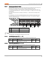
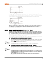
Parameter setting sequence
Parameters of each group are connected each other. Therefore, follow the below parameter
order.
Parameter 3 Group [PAR3] → Parameter 4 Group [PAR4] → Parameter 5 Group [PAR5] →
Parameter 2 Group [PAR2] → Parameter 1 Group [PAR1] → SV Setting [SV]
Changing Parameter 3 Group's parameters can sometimes reset other associated parameters.
Always make sure to check if such parameters have been affected.
5.2.2
Set value (SV) setting
①
②
38
Press any key among
,
,
in RUN mode to enter SV
setting mode. Last digit (100 digit) on SV display part flashes.
Press the
key to move digit.
(10 → 10 → 102 → 103 → 100)
0
1
③
Press the
④
Press the
key to save the set value. If there is no additional
key operations in 3 sec., the changed SV is automatically saved.
,
keys to raise or lower the set value.
© Copyright Reserved Autonics Co., Ltd.
5 Preparation and Startup
5.2.3
MV monitoring and manual control
①
②
While in RUN mode, press the
key to commence manual control. The SV display will
then show H (heating control) or C (cooling control) and simultaneously display the MV to
indicate commencement of MV monitoring.
If the
,
, or
is pressed while MV monitoring is in progress, the MAN indicator
will turn on and the last digit will start to flash to indicate activation of manual control.
key to change the flashing digit (100 → 101 → 102 → 103 → 100).
③
Press the
④
⑤
Select the digit and configure the desired MV value using the
,
keys.
To end manual control, press the
key. The MAN indicator will turn off, and the system
will revert to auto control mode.
While in heating & cooling control mode, set the manual heating MV and then press the
key to see C (cooling control) and the current cooling MV value on the SV display
indicating commencement of cooling MV monitoring.
If the
,
, or
is pressed while MV monitoring is in progress, the MAN indicator
turns on and the last digit starts to flash to indicate activation of manual control.
⑥
⑦
key to change the flashing digit (100 → 101 → 102 → 103 → 100).
⑧
Press the
⑨
Select the digit and configure desired cooling MV value using the
⑩
To end manual control, press the
key. The MAN indicator will turn off, and the system
will revert to auto control mode.
While in standard control mode (heating control or cooling control), pressing the
key
once from the MV monitoring stage, or any other stage, will revert the system to auto
control mode.
During heating & cooling control mode, pressing the
key once from the MV
monitoring stage, or any other stage, will skip the system to the cooling MV monitoring
stage.
⑪
⑫
© Copyright Reserved Autonics Co., Ltd.
,
keys.
39
5 Preparation and Startup
For heating & cooling control, the system reverts to auto control after going through heating
monitoring, manual heating control, cooling monitoring, and manual cooling control stages in
sequence.
Heating MV remains in effect during cooling monitoring and manual cooling control.
When setting ditial input function as AUTO/MANUAL, MV monitoring and control status
Control status
AUTO
MANUAL
MV
Not changed
Changeable
TK4N/S/SP model’s the
40
Monitoring
Avaliable
key alternates the
key.
© Copyright Reserved Autonics Co., Ltd.
5 Preparation and Startup
© Copyright Reserved Autonics Co., Ltd.
41
5 Preparation and Startup
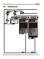
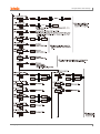
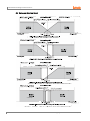
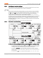
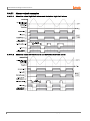
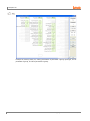
5.3
42
Parameter group
© Copyright Reserved Autonics Co., Ltd.
5 Preparation and Startup
© Copyright Reserved Autonics Co., Ltd.
43
5 Preparation and Startup
※1. PASS parameter will be displayed only when password is set. It is not displayed when
purchasing the unit since default password is set to 0000.
If password is not valid, the screen will be shifted to password code required window.
Press any key among
to return to password entering window. Press
key to return to RUN mode.
In case you forget password, contact Autonics A/S center after checking password
code.
※2. TK4N/4S/4SP do not have
key. The
key replaces
key.
※3. It is displayed when setting user parameter group in the integrated device
management program (DAQMaster).
44
Press
key over 2 sec in RUN mode to enter into setting mode.
Press
key for 1.5 sec while in setting mode to move to other parameter group.
Press
key over 3 sec while in setting mode to return to RUN mode.
Press
key at the last parameter of each parameter, it moves to that parameter name.
You can move to other groups.
If there is no additional key operation within 30 sec after entering into setting mode, it will be
automatically returned to RUN mode and previous setting value will be remained
The shaded parameters are displayed in common.
The others may not be displayed by the specifications of the product, other parameter’s
setting, or parameter mask setting.
© Copyright Reserved Autonics Co., Ltd.
5 Preparation and Startup
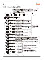
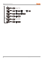
5.4
Parameter groups
5.4.1
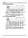
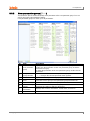
Parameter 1 group [PAR1]
© Copyright Reserved Autonics Co., Ltd.
45
5 Preparation and Startup
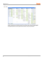
5.4.2
46
Parameter 2 group [PAR2]
© Copyright Reserved Autonics Co., Ltd.
5 Preparation and Startup
© Copyright Reserved Autonics Co., Ltd.
47
5 Preparation and Startup
5.4.3
48
Parameter 3 group [PAR3]
© Copyright Reserved Autonics Co., Ltd.
5 Preparation and Startup
※ OUT1, OUT2 output:
In case that OUT1, OUT2 output is relay output type
: OUT1, O!SR, O!MA, OUT2, O@SR, O@MA parameters are not displayed.
In case that OUT1,OUT2 output is current + SSR drive output type, when OUT1,OUT2
output is set to SSR
: Output method of O!SR, O@SR is held in STND and parameter is not displayed.
In case that OUT1, output is SSR drive output model of SSRP function and OUT2 output is
current + SSR drive output
- OUT1, O!MA are not displayed.
- O!SR can set to STND, CYCL, PHAS
-When O@SR is set to SSR it is held in STND and parameter is not displayed.
© Copyright Reserved Autonics Co., Ltd.
49
5 Preparation and Startup
5.4.4
50
Parameter 4 group [PAR4]
© Copyright Reserved Autonics Co., Ltd.
5 Preparation and Startup
© Copyright Reserved Autonics Co., Ltd.
51
5 Preparation and Startup
52
© Copyright Reserved Autonics Co., Ltd.
5 Preparation and Startup
5.4.5
Parameter 5 group [PAR5]
© Copyright Reserved Autonics Co., Ltd.
53
1
54
© Copyright Reserved Autonics Co., Ltd.
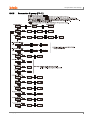
6 Parameter Settings and Functions
6
Parameter Settings and Functions
6.1
Input
6.1.1
Input types and temperature ranges
Input types
Display
Temperature range
Temperature range
(℃)
(℉)
1
KCaH
-200 to 1350
-328 to 2463
0.1
KCaL
-199.9 to 999.9
-199.9 to 999.9
1
JIcH
-200 to 800
-328 to 1472
0.1
JIcL
-199.9 to 800.0
-199.9 to 999.9
1
ECrH
-200 to 800
-328 to 1472
0.1
ECrL
-199.9 to 800.0
-199.9 to 999.9
1
TCcH
-200 to 400
-328 to 752
0.1
TCcL
-199.9 to 400.0
-199.9 to 752.0
K (CA)
J (IC)
E (CR)
T (CC)
Thermoc
ouple
(TC)
B (PR)
1
B PR
0 to 1800
32 to 3272
R (PR)
1
R PR
0 to 1750
32 to 3182
S (PR)
1
S PR
0 to 1750
32 to 3182
N (NN)
1
N NN
-200 to 1300
-328 to 2372
C (TT)※1
1
C TT
0 to 2300
32 to 4172
G (TT)※2
1
G TT
0 to 2300
32 to 4172
1
LIcH
-200 to 900
-328 to 1652
0.1
LIcL
-199.9 to 900.0
-199.9 to 999.9
1
UCcH
-200 to 400
-328 to 752
0.1
UCcL
-199.9 to 400.0
-199.9 to 752,0
Platinel II
1
PLII
0 to 1390
32 to 2534
Cu 50Ω
0.1
CU 5
-199.9 to 200.0
-199.9 to 392.0
Cu 100Ω
0.1
CU10
-199.9 to 200.0
-199.9 to 392.0
JPt 100Ω
1
JPtH
-200 to 650
-328 to 1202
JPt 100Ω
0.1
JPtL
-199.9 to 650.0
-199.9 to 999.9
DPt 50Ω
0.1
DPt5
-199.9 to 600.0
-199.9 to 999.9
DPt 100Ω
1
DPtH
-200 to 650
-328 to 1202
DPt 100Ω
0.1
DPtL
-199.9 to 650.0
-199.9 to 999.9
Nickel 120Ω
1
NI12
-80 to 200
-112 to 392
L (IC)
U (CC)
RTD
© Copyright Reserved Autonics Co., Ltd.
55
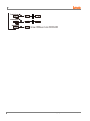
6 Parameter Settings and Functions
Input types
Display
0 to 10V
AV1
0 to 5V
AV2
1 to 5V
AV3
Voltage
Analog
0 to 100mV
AMV1
0 to 20mA
AMA1
4 to 20mA
AMA2
Temperature range
Temperature range
(℃)
(℉)
-1999 to 9999
(Display point will be changed according to
decimal point position)
Current
※1. C (TT): Same temperature sensor as former W5 (TT).
※2. G(TT): Same temperature sensor as former W (TT).
Temperature sensors are to convert subject temperature to electrical signals for the temperature
controller allowing it to control output.
SV (Setting Value) can only be set within the input range and do not set over the input range.
6.1.2
Input type [PAR3 → IN-T]
This product supports multiple input types, making it possible for the user to choose from
thermocouples, resistors, and analog voltage/current.
If you change the input specification, the SV's upper/low-limits are automatically set to the new
specification's max/min values for temperature sensors. As for analog inputs, analog upper/lower
input values are set to the max/min temperature range and the SV upper/low-limits set to
upper/lower scale values. Therefore, you need to reconfigure the settings.
6.1.3
Setting
group
Parameter
Setting range
Factory
default
Unit
PAR3
IN-T
Refer to 6.1.1. Input types and
temperature
KCaH
-
Sensor temperature unit [PAR3 → UNIT]
When selecting the input temperature sensor, you can set the desired units (℃, ℉) of
temperature/scale value to be displayed.
Setting
group
Parameter
Setting range
Factory
default
Unit
PAR3
UNIT
?C / ?F
?C
-
This parameter will not be displayed if analog input has been selected.
56
© Copyright Reserved Autonics Co., Ltd.
6 Parameter Settings and Functions
6.1.4
Analog input/scale value
With analog input selected, you can set the analog input range (high/low limit input values) and
the display scale (high/low limit scale values) within the designated input range.
The decimal point positions remain fixed when configuring the high/low limit input values. You
can change the input values at AV1: 00.00, AV2/AV3: 0.000, AMV1: 000.0, AMA1/ AMA2: 00.00
decimal points.
If the upper and lower limit scale settings are identical, ERRflashes twice and setting mode is
displayed.
For analog input, ±5% of the set high/low limit input value is extended. Analog output is also
extended compairing input value. (For temperature sensor input, ±5% extension is applied
within the temperature range.)
No.
①
PV
±5% section
Display
Flashes PV
②
±5 to 10% section
Flashes HHHH or LLLL
③
Over ±10% section
Flashes OPEN
This parameter is not displayed for temperature sensor input.
6.1.4.1
Low-limit input value [PAR3 → L-RG]
You can set the low limit input values for actual use within the analog input range.
6.1.4.2
Setting
group
Parameter
Setting range
Factory
default
Unit
PAR3
L-RG
Minimum temperature range to high-limit
input value [H-RG] - F.S. 10%
0)00
-
High-limit input value [PAR3 → H -RG]
You can set high limit input values for actual use within the analog input range.
Setting
group
Parameter
Setting range
Factory
default
Unit
PAR3
H-RG
Low-limit input value [L-RG] + F.S. 10% to
maximum temperature range
1)00
-
© Copyright Reserved Autonics Co., Ltd.
57
6 Parameter Settings and Functions
6.1.4.3
Scale decimal point position [PAR3 → DOT]
You can set the decimal point positions for present value (PV) and set value(SV) within high and
low limit scale values.
Setting
group
PAR3
6.1.4.4
Parameter
Setting range
DOT
0 / )0/ )00 / )000
Factory
default
)0
Unit
-
Low-limit scale value [PAR3 → L-SC]
You can set the display scales of low-limit values for analog input [L-RG]. (Based on the decimal
point position setting.)
Setting
group
PAR3
6.1.4.5
Parameter
Setting range
L-SC
`999 to 9999
Factory
default
00)0
Unit
-
High-limit scale value [PAR3 → H-SC]
You can set the display scales of high-limit values for analog input [H-RG]. (Based on the
decimal point position setting.)
Setting
group
PAR3
6.1.4.6
Parameter
Setting range
H-SC
`999 to 9999
Factory
default
10)0
Unit
-
Display unit for front panel [PAR3 → dUNT]
When you select an analog input type, you can set the display units.
58
Setting
group
Parameter
Setting range
Factory
default
Unit
PAR3
dUNT
?C / ?F / ?/O / OFF
?/O
-
Setting
Parameter description
?C
Sets the display unit to ℃ and turns on the ℃ of front unit indicator.
?F
Sets the display unit to ℉ and turns on the ℉ of front unit indicator.
?/O
Sets the display unit to % and turns on the % of front unit indicator.
OFF
Sets the display unit to an undefined unit. The LED unit indicator will not turn on.
© Copyright Reserved Autonics Co., Ltd.
6 Parameter Settings and Functions
6.1.5
Input correction [PAR3 → IN-B]
This feature is used to compensate for input correction produced by thermocouples, RTDs, or
analog input devices, NOT by the controller itself.
The Input correction function is mainly used when the sensor cannot be attached directly to
controlled objects. It is also used to compensate for temperature variance between the sensor's
installation point and the actual measuring point.
Setting
group
Parameter
Setting range
Factory
default
Unit
PAR3
IN-B
-999 to 0999 (temperature H, analog)
`9(9 to 99(9 (temperature L)
0000
℃/℉/-
If the controller displays 78℃ when the actual temperature is 80℃, set the input correction [INB] as ‘002’ in order to adjust the controller's display temperature to 80℃.
If present value after input correction is out of the input range by each input sensor, it displays
‘HHHH’ or ‘LLLL’.
Make sure that an accurate temperature variance measurement is taken before set values of
input correction. An inaccurate initial measurement can lead to greater variance.
Many of today's temperature sensors are graded by their sensitivity. Since higher accuracy
usually comes at a higher cost, most people tend to choose sensors with medium sensitivity.
Measuring each sensor's sensitivity correction for input correction feature in order to ensure
higher accuracy in temperature reading.
6.1.6
Input digital filter [PAR3 → MAvF]
It is not possible to perform stable control if the present value (PV) fluctuates because of fast
changes of input signal. Using the Input digital Filter function can stabilize PV to realize more
reliable control.
Setting
group
PAR3
Parameter
Setting range
MAvF
00)1 to12)0
Factory
default
)1
Unit
Sec
If the input digital filter is set to 0.4 sec., digital filtering is applied to a sampling value collected
over 0.4 sec. (400 ms).
When the input digital filter is used, present value (PV) can vary from the actual input value.
© Copyright Reserved Autonics Co., Ltd.
59
6 Parameter Settings and Functions
6.1.7
High/Low-limit value of setting value(SV) [PAR3 → H-SV/ L-SV]
You can limit the Set value(SV) range within the temperature range of the temperature sensor or
analog input type in order to prevent the system from controlling with improper SV.
Setting
group
Parameter
Setting range
Factory default
SV low-limit + 1 digit to sensor
input high-limit or analog highlimit scale value
1350(temperature)
H-SV
Sensor low-limit or analog lowlimit scale value to SV high-limit 1 digit
-200(temperature)
L-SV
PAR3
Parameter
L-SV
Parameter Description
Set value(SV) low-limit
H-SV
Set value(SV) high-limit
00)0(analog)
10)0(analog)
Unit
℃/℉
℃/℉
Attempts to set the limits outside the min/max input range, or analog's high/low-limits, are not
accepted. Instead, the previous settings are retained.
Set value(SV) can only be set within the SV low-limit [L-SV] and SV high-limit [H-SV] range.
SV lower-limit [L-SV] cannot exceed SV high-limit [H-SV].
60
© Copyright Reserved Autonics Co., Ltd.
6 Parameter Settings and Functions
6.2
Control output
6.2.1
Control output mode [PAR3 → O-FT]
6.2.1.1
Control output modes for general temperature control include heating, cooling, and heating
& cooling.
Heating control and cooling control are mutually opposing operations with inverse outputs.
The PID time constant varies based on the controlled objects during PID control.
Setting
group
Parameter
Set range
PAR3
O-FT
Standard model: HEAT / COOL
Heating/Cooling model: HEAT / COOL / H-C
Factory
default
HEAT
H-C
Unit
-
Heating control [PAR3 → O-FT → HEAT]
Heating control mode: the output will be provided in order to supply power to the load (heater) if
present value (PV) falls below set value(SV).
6.2.1.2
Cooling control [PAR3 → O-FT → COOL]
Cooling control mode: the output will be provided in order to supply power to the load (cooler) if
present value (PV) rises above set value(SV).
6.2.1.3
Heating & Cooling control [PAR3 → O-FT → H-C]
Heating & Cooling control mode: heating & cooling with a single temperature controller when it is
difficult to control subject temperature with only heating or cooling.
Heating & Cooling control mode controls the object using different PID time constants for each
heating & Cooling.
It is also possible to set heating & cooling control in both PID control or ON/OFF control mode.
Heating/cooling output can be selected among Relay output, SSR drive output and current
output depending on model types choosen according to your application environment. (Note that
SSR drive output of OUT2 operates standard control.)
© Copyright Reserved Autonics Co., Ltd.
61
6 Parameter Settings and Functions
For heating & cooling control, OUT1 control output is dedicated to heating control and OUT2
control output to cooling control.
6.2.1.3.1.
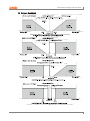
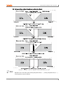
Dead band/Overlap band [PAR2 → DB]
In heating & cooling control, it is possible to designate a dead band between heating & cooling
control bands based on set value(SV).
A dead band forms around the SV when positive (+) value is set. No control occurs in the dead
band area. Therefore, heating & cooling MVs become 0.0% in the formed dead band.
An overlap band (simultaneous application of heating & cooling MVs) forms around the SV when
negative (-) value is set.
Set as 0 when a dead band or an overlap band is not used.
When setting integration time, it is applied when the intengration time of heating control and
cooling control is set. In case of PI-P control and P-PI control, it also operates as P-P control.
Setting
group
Parameter
Setting range
PAR2
DB
See below.
Factory
default
See
below.
Unit
PID/PID, PID/ON-OFF, and ON-OFF/PID Control
Set range (temperature): -(proportional band) to +(proportional band) (the lower value
when using different proportional bands)
Set range (analog): -99.9 to 099.9
Factory default: 0000 (temperature H), 000.0 (temperature L, analog),
(unit: temperature ℃/℉, analog % F.S.)
ON-OFF/ON-OFF Control
Set range (temperature):
-999 (overlap band) to 0000 (not used) to 0999 (dead band) (temperature H)
-199.9 (overlap band) to 000.0 (not used) to 999.9 (dead band) (temperature L)
Set range (analog): -99.9 (overlap band) to 000.0 (not used) to 099.9 (dead band)
Factory default: 0000 (temperature H), 000.0 (temperature L, analog),
(unit: temperature ℃/℉, analog % F.S.)
62
© Copyright Reserved Autonics Co., Ltd.
6 Parameter Settings and Functions
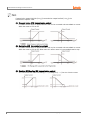
(1) Using a Deadband
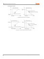
© Copyright Reserved Autonics Co., Ltd.
63
6 Parameter Settings and Functions
(2) Using an Overlap Band
64
© Copyright Reserved Autonics Co., Ltd.
6 Parameter Settings and Functions
(3) Using neither a Dead band nor an Overlap Band
Depends on the set value of the heating integration time[H-I], cooling integration time[C-I],
actual operation may be different.
© Copyright Reserved Autonics Co., Ltd.
65
6 Parameter Settings and Functions
6.2.2
MV High/Low-limit value settings [PAR2 → H-MV / L-MV]
MV high/low-limit values [H-MV / L-MV] for control output can be configured to the actual MV,
provided the temperature controller's MV calculation exceeds the limits.
During heating & cooling control, cooling MV carries a "-" prefix. Therefore, the high-limit is
expressed as a + value on the heating side and the low-limit as a - value on the cooling side.
Parameter
Description
L-MV
MV Low-limit value setting
H-MV
MV High-limit value setting
Setting
group
Parameter
H-MV
PAR2
L-MV
Factory
default
Set range
Unit
Standard Control: MV Low-limit value [L-MV]
+ )1 to 10)0
10)0
%
Heating & Cooling Control: 00)0 to 10)0
(PID control)
)0 (OFF)/10)0 (ON) (ON/OFF control)
10)0
%
Standard Control: 00)0 to MV high-limit value
[H-MV] – )1
)0
%
Heating & Cooling Control: `0)0 to 00)0
(PID control), `0)0 (ON)/ )0 (OFF) (ON/OFF
control)
`0)0
%
Same MV limits applied during auto-tuning.
MV limits are not applied to manual control, MV upon control stop, MV upon a sensor error, and
initial manual control MV.
MV high/low-limit configuration is not available for ON/OFF control in standard control mode
(heating or cooling control).
66
© Copyright Reserved Autonics Co., Ltd.
6 Parameter Settings and Functions
6.2.3
Ramp settings [PAR2 → RAMU/ RAMD/ rUNT]
Ramp is a feature used to configure the slope toward set value(SV). The feature limits change
rate of set value(SV) and thereby restricts sudden temperature changes (increase and decrease)
in the control subject.
Ramp is commonly used in applications where rapid temperature changes (increase and
decrease) could impact negatively on the control subject.
Parameter
RAMU
Description
Settings for Ramp-up change rate.
RAMD
Settings for Ramp-down change rate.
rUNT
Settings for Ramp time unit.
Setting
group
PAR2
Factory
default
Parameter
Setting range
RAMU
000 to 999 (temperature H, analog),
00)0 to 99(9 (temperature L)
000
RAMD
000 to 999 (temperature H, analog),
00)0 to 99(9 (temperature L)
000
rUNT
SEC (seconds), MIN (minutes),
HOUR (hours)
MIN
Unit
-
Activating the ramp feature when the ramp is not in operation limits the change rate of Set
value(SV) based on present value (PV). Changing SV or ramp parameters while the ramp is in
operation limits the change rate of SV based on SV at the point of the change.
Control will be carried out based on changed SV (hereinafter referred to as RAMP SV) changed by preset change rate (slope). RAMP-Up Change Rate and RAMP-Down Change Rate
can be configured independently.
Alarm operation during RAMP will be made based on final SV.
Setting the rate of ramp change to 0 deactivates the ramp feature.
If the ramp feature has been activated, RAMP SV will be displayed on SV display part.
Ramp depending on operation status
Operation Status
All operations
Ramp Up/Down
Ramp
When it is 0.
Inactive
OPEN, HHHH, LLLL, Auto-tuning, Switching from
Auto to Manual, Switching from Run to Stop
Irrespective of
conditions.
Inactive
OPEN, HHHH, LLLL, After Auto-tuning completed, PV
= SV
Irrespective of
conditions.
Inactive
Power On, SV Change, Switching from Stop to Run,
Switching from Manual to Auto, Ramp Rate Change
When it is not 0.
Active
© Copyright Reserved Autonics Co., Ltd.
67
6 Parameter Settings and Functions
Ramp operation graph
(1 to 9999 digit)
(1 to 9999 digit)
68
© Copyright Reserved Autonics Co., Ltd.
6 Parameter Settings and Functions
6.2.4
Auto/Manual control settings
Auto control mode is to make temperature reach SV with MV calculated by PID control. Manual
control mode is to make temperature reach SV with user’s defined MV.
When in manual control mode, parameter settings can only be viewed and cannot be modified
(except for lock parameters). When digital input terminal function is set as Auto/Manual control,
the
key (the
key for TK4N, TK4S, TK4SP) and the Auto/Manual swithcing by
communication do not operate. When the unit is powered on following a power interruption or
shutdown, previous control mode (auto or manual) will be maintained.
If switching to manual control during Auto-tuning, Auto-tuning will be terminated. It is still possible
to switch to manual control mode while in STOP. When a sensor break alarm [SBA] occurs in
standard control mode, the sensor error MV [ErMV] is applied. In this state, manual and auto
control MV settings can be modified. It is still possible to switch auto/manual control mode while
in controlling operation.
Operation Priority: Manual Control > Stop > Open (Sensor Disconnection)
6.2.4.1
Manual/Auto control switching
(1) Manual control switching for standard control (heating or cooling control)
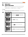
①, ⑤: When in RUN mode, press the
key (the
key for TK4N, TK4S, TK4SP
model) and it enters MV monitoring mode. The SV display shows H (heating control) or
C (cooling control), and shows MV to indicate the start of MV monitoring.
②, ⑥: If the
is pressed when MV monitoring is in progress, the MAN
0
indicator comes on and the lowest digit (10 digit) starts to flash, indicating activation of
manual control.
③, ⑦: Press the
© Copyright Reserved Autonics Co., Ltd.
key to change the flashing digit (10 → 10 → 10 → 10 → 10 ).
0
1
2
3
0
69
6 Parameter Settings and Functions
④, ⑧: Select the digit and configure the desired MV value using the
moving to 0→1→2→3→4→5→6→7→8→9→0 by the
keys
keys.
⑨: In ① to ⑧ status, press the
key(the
key for TK4N, TK4S, TK4SP
model) to end manual control. The MAN indicator goes off and the system reverts to
auto control mode.
(2) Manual control switching for heating & cooling control
①: When in RUN mode, press the
key (the
key for TK4N, TK4S, TK4SP
model) and it enters heating MV monitoring mode. The SV display shows ‘H’ and
shows MV to indicate the start of heating MV monitoring.
②: If the
is pressed when heating MV monitoring is in progress, the MAN
0
indicator comes on and the lowest digit (10 digit) starts to flash, indicating activation of
manual control.
③: Press the
④: Select the digit and configure the desired MV value using the
key to change the flashing digit (10 → 10 → 10 → 10 → 10 ).
0
moving to 0→1→2→3→4→5→6→7→8→9→0 by the
1
2
3
0
keys
keys.
⑤: In ① to ④ status, press the
key(
key for N, S, SP model) and it enters
cooling MV monitoring mode. The SV display shows ‘C’ and shows MV to indicate the
start of cooling MV monitoring.
⑥: If the
is pressed when cooling MV monitoring is in progress, the lowest
0
digit (10 digit) starts to flash.
⑦: Press the
⑧: Select the digit and configure the desired MV value using the
key to change the flashing digit (10 → 10 → 10 → 10 → 10 ).
0
moving to 0→1→2→3→4→5→6→7→8→9→0 by the
1
2
3
0
keys
keys.
⑨: In ⑤ to ⑧ status, press the
key(the
key for TK4N, TK4S, TK4SP
model) to end manual control. The MAN indicator goes off and the system reverts to
auto control mode.
After heating & cooling control, the system reverts to auto control in sequence of heating
monitoring, manual heating control, cooling monitoring, and manual cooling control.
Heating MV remains in effect during cooling monitoring and manual cooling control.
TK4N/S/SP (W48×H48mm) does not have the
between auto and manual controls.
key. Press the
key once to change
If the digital Input [DI-1, DI-2] feature has been set for AUTO/MANUAL, the
key ( the
key for TK4N, TK4S and TK4SP model) key located on the front and automatic/manual
control functions via communication do not act.
(3) Manual/Auto Control switching with the digital input (DI) terminal
If the digital Input (DI) feature has been configured for manual/auto control switching, turn
on the DI to activate manual control (MAN indicator goes on) and turn off the DI to activate
auto control. If the digital Input feature is automatic control status, you can be only to
monitor. In case it is manual control status, modifying MV and monitoring are possible.
See 6.7.4 Digital input, for detailed information on digital Input (DI) terminal settings.
When MV parameter is masked, MV parameter cannot be monitored and changed.
70
© Copyright Reserved Autonics Co., Ltd.
6 Parameter Settings and Functions
6.2.4.2
Baseline MV for manual control [PAR5 → ItMV]
When switching from auto control [AUTO] to manual control [PrMU] you can set the initial MV.
AUTO: Controlling with auto control MV as an initial MV for manual control
PrMV: Controlling with preset manual MV [PrMV] as an initial MV.
Auto-MV[AUTO]
Preset MV[PrMV]
Setting
group
Parameter
Setting range
Factory default
Unit
PAR5
ItMV
AUTO / PrMV
AUTO
-
When re-supplying the power, it controls with the MV which is at the power OFF.
6.2.4.3
Initial MV for manual control [PAR5 → PrMV]
If the baseline MV for manual control is configured to PrMV (Preset Manual MV), you can set the
initial MV for manual control.
Setting
group
Parameter
Setting range
Standard
control
PAR5
PrMV
Heating
&
Cooling
control
ON/OFF
control
00)0 (OFF)
/10)0 (ON)
PID
control
00)0 to10)0
ON/OFF
control
`0)0 (Cooling ON)
/ 00)0(OFF)
/10)0 (Heating ON)
PID
control
`0)0 (Cooling) to
00)0 (OFF) to
10)0 (Heating)
Factory
default
Unit
00)0
%
When in heating & cooling control mode, a setting between )1 and 10)0 will be applied as
heating MV and a setting between )1 and `0)0 will be applied as cooling MV.
© Copyright Reserved Autonics Co., Ltd.
71
6 Parameter Settings and Functions
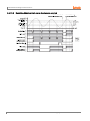
6.2.5
Output settings
6.2.5.1
Control output (OUT1/OUT2) selection [PAR3 → OUT1/OUT2]
In case of selecting the Models with current control output, both current and SSR drive
outputs are available. You can therefore choose the right output type depending on
application environments.
OUT1: Selects OUT1 control output.
OUT2: Selects OUT2 control output.
Setting
group
PAR3
6.2.5.2
Parameter
OUT1
OUT2
Setting range
Factory
default
Unit
SSR / CURR
SSR
-
SSRP function [PAR3 → O!SR]
SSRP function of SSR drive output is selectable one of standard ON/OFF control, cycle, phase
control. By parameter setting, standard SSR drive is available. Also, cycle control connecting
with a zero cross turn-on method SSR, phase control connectiong with a random turn-on method
SSR are available.
Realizing high accuracy and cost effective temperature control with both current output (4-20mA)
and linear output(cycle control and phase control).
(1) Standard ON/OFF control [STND]
A mode to control the load in the same way as Relay output type.(ON: output level 100%,
OFF: output level 0%)
(2) Cycle control [CYCL]
A mode to control the load by repeating output ON / OFF according to the rate of output
within setting cycle. Having improved ON / OFF noise feature by Zero Cross type.
(3) Phase control [PHAS]
A mode to control the load by controlling the phase within AC half cycle. Serial control is
available. Random turn-on SSR must be used for this mode.
72
Setting
group
Parameter
Setting range
Factory
default
Unit
PAR3
O!SR
STND / CYCL/ PHAS
STND
-
© Copyright Reserved Autonics Co., Ltd.
6 Parameter Settings and Functions
6.2.5.3
Make sure that SSRP function is not available for OUT2. In case of current type models,
SSR is fixed to standard output [STND] only.
When selecting cycle output [CYCL] or phase output [PHAS], the power supply for the load
and temperature controllers must be the same.
In case of selecting SSRP function whether cycle output [CYCL] or phase output [PHAS]
with PID control type, control cycle is not available to set.
Current output range settings [PAR3 → O!MA/O@MA]
If the control output is set to current output, you can select upper and low-limit range for the
current output as either 4-20mA or 0-20mA.
O!MA: Sets OUT1's current output range.
O@MA: Sets OUT2's current output range.
This parameter is only available on models supporting current output [OUT1, OUT2].
6.3
Temperature control
6.3.1
Temperature control mode [PAR3 → C-MD]
You can choose the type of temperature control method.
Description
Heating
PID control
ON/OFF control
PID control
PID control
ON/OFF control
ON/OFF control
Setting
PID
ONOF
pP
pON
OnP
OnON
Standard
Control
Heating &
Cooling
Control
Setting
group
PAR3
Parameter
Setting range
C-MD
Standard
Control
Heating &
Cooling
Control
© Copyright Reserved Autonics Co., Ltd.
Cooling
PID control
ON/OFF control
PID control
ON/OFF control
Factory
default
PID / ONOF
PID
pP / pON / OnP / OnON
pP
Unit
-
73
6 Parameter Settings and Functions
6.3.2
ON/OFF control [PAR3 → C-MD → ONOF]
Controls the temperature by comparing present value (PV) with set value(SV) and turning power
to the load on or off.
6.3.2.1
Hysteresis [PAR2 → hHYS/hOFT/cHYS/cOFT]
Hysteresis is to adjust control output ON/OFF point in ON/OFF control mode. ON_Hysteresis
sets the output on point and OFF_Offset sets the off point.
Setting hysteresis too low can result in hunting induced by disturbance (noise, chattering, etc.).
To minimize hunting, set ON_Hysteresis and OFF_Offset values with consideration to the heater
or cooler's capacity and thermal characteristics, the control subject's response characteristics,
the sensor's response characteristics and installation conditions, and other defining factors.
Parameter
hHYS
hOFT
Description
Configures ON_Hysteresis for heating control.
Configures OFF_Offset for heating control.
cHYS
Sets ON_Hysteresis for cooling control.
cOFT
Sets OFF_Offset for cooling control.
Setting
group
PAR2
Parameter
Setting range
Factory
default
hHYS
Temperature H, Analog: 001 to100
Temperature L: 0)1 to1)0
002
Temperature H, Analog: 001 to100
Temperature L: 0)1 to1)0
000
cHYS
hOFT
cOFT
74
Unit
℃/℉/-
© Copyright Reserved Autonics Co., Ltd.
6 Parameter Settings and Functions
6.3.3
PID control [PAR3 → C-MD → PID]
PID control is a combination of proportional (P), integral (I), and derivative (D) controls and offers
superb control over the control subjects, even with a delay time.
Proportional control (P) implements smooth,
hunting-free control; integral control (I) automatically corrects offsets;
and derivative control (D) speeds up the response to disturbance. Through these actions, PID
control realizes ideal temperature control.
Applied PID Control Technique
6.3.3.1
Proportional Control (P): Select PID control and set the integral and derivative time to 0000.
Proportional Integral Control (PI): Select PID control and set the derivative time to 0000.
Proportional Derivative Control (PD): Select PID control and set the integral time to 0000.
Multi SV: Use the same PID time constant for the values of SV0 to SV3.
Proportional band settings [PAR2 → H-P/C-P]
When present value (PV) is within the Proportional Band (P), the ON/OFF ratio needs to be
adjusted during the proportional period (T). The defined proportional control (time proportional
control) section is called as the proportional band.
Parameter
H-P
Heating proportional band
C-P
Cooling proportional band
Setting
group
PAR2
6.3.3.2
Description
Parameter
H-P
C-P
Setting range
Factory
default
Unit
00)1 to 99(9
01)0
Temperature: ℃/℉
Analog: %
Integral time settings [PAR2 → H-I/C-I]
MVs from integral and proportional operation become the same when deviation is consistent.
The time taken for the two MVs to match is called the integral time.
Parameter
H-I
Description
Heating integral time
C-I
Cooling integral time
Setting
group
PAR2
Parameter
H-I
C-I
Setting range
Factory
default
Unit
0000 to 9999
0000
Sec
© Copyright Reserved Autonics Co., Ltd.
75
6 Parameter Settings and Functions
Integral control is not conducted if the integral time is set to 0.
Setting the integral time too short can intensify correction movements and cause hunting.
6.3.3.3
Derivative time settings [PAR2 → H-D/C-D]
In accordance with the deviation of the ramp, the time taken for the MV gained from derivative
operation to reach the MV gained from proportional control is called the derivative time.
Parameter
H-D
Description
Heating derivative time
C-D
Cooling derivative time
Setting
group
PAR2
Parameter
H-D
C-D
Setting range
Factory
default
Unit
0000 to 9999
0000
Sec
Derivative control is not conducted if the derivative time is set to 0.
6.3.3.4
Control period settings [PAR3 → H-T/C-T]
If relay or SSR is used to output MV under proportional control, the output is on for a fixed
amount of time (within the control period, as a percentage of the MV) and then remains off for
the rest of the time. The preset period when output ON/OFF takes place is called the
proportional control period.
Control with SSR drive output has a faster response than that of relay output. Therefore, by
configuring a shorter control period, more responsive temperature control is achieved.
Parameter
H-T
Description
Heating control period
C-T
Cooling control period
Setting
group
Parameter
H-T
PAR3
C-T
Setting range
Factory default
Unit
Relay, SSR drive
output(ON/OFF control,
phase control, cycle
control): 00)1 to12)0
Current output, SSR
drive output: 00)1
to12)0
Relay output: 02)0
SSR drive output: 00@0
Sec
If using heating & cooling control, configure each control period separately for heating & cooling.
76
© Copyright Reserved Autonics Co., Ltd.
6 Parameter Settings and Functions
6.3.3.5
Offset correction/Manual reset settings [PAR2 → REST]
When selecting P / PD control mode, there are certain temperature differences even after PV
reaches stable status since heater’s rising and falling time is inconsistent due to thermal
characteristics of control objects, such as heat capacity and the heater capacity. This
temperature difference is called OFFSET. Offset can be corrected using manual reset.
Setting
group
Parameter
Setting range
Factory
default
Unit
PAR2
REST
0)0 to 10)0
5)0
%
(1) Manual Reset Adjustments based on Control Results
Under stable control conditions, set the offset to 50% if PV and SV are identical, to over
50.0% if PV is lower than SV, and to below 50.0% if PV is higher than SV.
The offset correction feature can only be used when proportional control is in effect. If setting the
integral value to 0, the manual reset parameter will be displayed.
The user cannot configure the manual reset setting during heating & cooling control. Instead, the
setting is automatically set to 0% for both heating & cooling.
Applicable only when integral time is set to 0 under P control or PD control only.
Switching from heating & cooling control to standard control (P, PD control) automatically
configures the reset setting to 50%.
6.3.4
Auto-tuning
Auto tuning measures the control subject's thermal characteristics and thermal response rate,
and then determines the necessary PID time constant. (When control type [C-MD] is set as PID,
it is displayed.)
If error [OPEN] occurs during auto tuning, it stops this operation automatically.
To stop auto tuning, change the set as OFF. (It maintains P, I, D values of before auto tuning.)
6.3.4.1
Auto-tuning start/stop setting [PAR2 → AT]
Auto-tuning automatically stores PID time constants upon termination. These PID time
constants can then be modified by the user to suit their usage environment.
When auto-tuning is in progress, the AT indicator located on the front of the controller
flashes in 1 sec. intervals. When auto-tuning finishes, the AT indicator automatically goes off
and the auto-tuning parameter will return to OFF.
When auto-tuning is in progress and digital input key [DI-K] is STOP(switching
RUN/STOP) or AT(auto-tuning RUN/STOP) is set, and digital input terminal function [DI-1,
DI-2] is STOP (switching RUN/STOP) or MAN(AUTO/MANUAL control selection), autotuning will be automatically ended, if concerned DI is inputted or a sensor disconnection
error occurs. (Restored the PID used prior to the auto-tuning session)
© Copyright Reserved Autonics Co., Ltd.
77
6 Parameter Settings and Functions
Setting
OFF
Description
Auto-tuning complete.
ON
Auto-tuning in progress.
Setting
group
Parameter
Setting range
Factory
default
Unit
PAR2
AT
OFF/ON
OFF
-
Auto-tuning continues to run even if the temperature reading exceeds or falls below the input
range.
When auto-turning is in progress, parameters can only be referenced and not altered.
Auto-tuning is not available in manual control.
6.3.4.2
Auto-tuning mode settings [PAR3 → AtT]
Auto-tuning is available in [TUN1] mode (based on SV) or [TUN2] mode (based on 70% of SV),
depending on the baseline value used.
Setting
TUN1
Description
Auto-tunes and derives a PID time constant based on set value(SV).
TUN2
Auto-tunes and derives a PID time constant based on 70% of set value(SV).
Setting
group
Parameter
Setting range
Factory
default
Unit
PAR3
AtT
TUN1 / TUN2
TUN1
-
In cooling control mode, [TUN2] mode calculates 70% based at 0.
When SV=-100, [TUN2] is performed at -70.
78
© Copyright Reserved Autonics Co., Ltd.
6 Parameter Settings and Functions
6.4
Alarm output
There are three alarms which operate individually. You can set combined qoralarm operation and
alarm option. Use digital input setting as [AlRE] or turn OFF power and re-start this unit to
release alarm operation.
6.4.1
Alarm operation [PAR4 → AL-1/AL-2/AL-3]
Select the desired alarm operation.
Mode
OFF
DVCC
]]DV
]DV[
CDU]
PVCC
]]PV
LBA
Name
Alarm operation
Description (factory default)
-
-
No alarm output
Deviation
high-limit
alarm
Deviation
low-limit
alarm
Deviation
high/lowlimit
alarm
Deviation
high/lowlimit
reverse
alarm
Absolute
value
high limit
alarm
Absolute
value low
limit
alarm
Loop
break
alarm
High deviation:
Set as 10℃
Lower deviation: Set
as 10℃
High deviation:
Set as -10℃
Lower deviation: Set
as -10℃
Lower deviation: Set as 10℃,
High deviation: Set as 20℃
Lower deviation: Set as 10℃,
High deviation: Set as 20℃
Alarm absolute value:
Set as 90℃
Alarm absolute value:
Set as 90℃
-
© Copyright Reserved Autonics Co., Ltd.
If deviation between PV and SV as
high limit is higher than set value of
deviation
temperature, the alarm output will be
ON.
High-limit deviation temperature can
be set in AL!H/AL@H/AL#H.
If deviation between PV and SV as
low limit is higher than set value of
deviation temperature, the alarm
output will be ON.
Low limit can be set in AL!L/AL@L/
AL#H.
If deviation between PV and SV as
high/low limit is higher than set value
of deviation temperature, the alarm
output will be ON.
High-limit Deviation Temperature can
be set in AL!H/AL@H/AL#H.
Low limit can be set in AL!L/AL@L/
AL#H.
If deviation between PV and SV as
high/low-limit is higher than set value
of deviation temperature, the alarm
output will be OFF.
High-limit deviation can be set in
AL!H/AL@H/AL#H.
Low limit deviation can be set in
AL!L/AL@L/AL#H.
Alarm absolute value:
Set as 110℃
If PV is higher than the absolute
value, the output will be ON.
Alarm's absolute value can be set in
AL!H/AL@H/AL#H.
Alarm absolute value:
Set as 110℃
If PV is lower than the absolute value,
the output will be ON.
Alarm's absolute value can be set in
AL!L/AL@L/AL#H.
It will be ON when it detects loop
break.
79
6 Parameter Settings and Functions
Mode
Name
Alarm operation
Description (factory default)
SBA
Sensor
break
alarm
-
It will be ON when it detects sensor
disconnection.
HBA
Heater
break
alarm
-
It will be ON when CT detects heater
break.
※H: Alarm output □ hysteresis [A□.HY]
Parameter
AL-1
Selects alarm output 1 operation mode.
AL-2
Selects alarm output 2 operation mode.
AL-3
Selects alarm output 3 operation mode.
Setting
group
Description
Parameter
Factory
default
Setting range
AL-1
PAR4
AL-2
AL-3
80
Unit
DVCC
OFF / DV[[/ ]]DV / ]DVC / [DV] /
PVCC / ]]PV / SBA / LBA / HBA
]]DV
-
OFF
© Copyright Reserved Autonics Co., Ltd.
6 Parameter Settings and Functions
6.4.2
Alarm output options [PAR4 → AL!T/AL@T]
Users can select the desired alarm output options.
Setting
Mode
Description
If it is an alarm condition, alarm output is ON. If it is a clear
alarm condition, alarm output is OFF.
AL-A
Standard Alarm
AL-B
Alarm latch ※1
If it is an alarm condition, alarm output is ON and maintains
ON status.
AL-C
Standby
sequence1※2
First alarm condition is ignored and from second alarm
condition, standard alarm operates.
When power is supplied and it is an alarm condition, this first
alarm condition is ignored and from the second alarm
condition, standard alarm operates.
AL-D
Alarm latch and
standby
sequence1
If it is an alarm condition, it operates both alarm latch and
standby sequence. When power is supplied and it is an alarm
condition, this first alarm condition is ignored and from the
second alarm condition, alarm latch operates.
Standby
sequence2
First alarm condition is ignored and from second alarm
condition, standard alarm operates.
When re-applied standby sequence and if it is alarm condition,
alarm output does not turn ON.
After clearing alarm condition, standard alarm operates.
Alarm latch and
standby
sequence2
Basic operation is same as alarm latch and standby
sequence1. It operates not only by power ON/OFF,
but also alarm set value, or alarm option changing. When reapplied standby sequence and if it is alarm condition, alarm
output does not turn ON.
After clearing alarm condition, alarm latch operates.
AL-E
AL-F
Condition of re-applied standby sequence for standby sequence 1, alarm latch and standby
sequence 1: Power ON
Condition of re-applied standby sequence for standby sequence 2, alarm latch and standby
sequence 2: Power ON, changing set temperature, alarm temperature[AL1, AL2, AL3] or
alarm operation[AL-1, AL-2, AL-3], switching STOP mode to RUN mode.
Parameter
AL!T
Description
Selects the operation mode of alarm output 1.
AL@T
Selects the operation mode of alarm output 2.
AL#T
Selects the operation mode of alarm output 3.
Setting
group
Parameter
Setting range
Factory
default
Unit
AL-A / AL-B / AL-C / AL-D / AL-E /
AL-F
AL-A
-
AL!T
PAR4
AL@T
AL#T
If alarm operation is set as loop break alarm [LBA], sensor break alarm [SBA], or heater break
alarm[HBA], only standard alarm [AL-A] and alarm latch [AL-C] of alarm option are displayed.
© Copyright Reserved Autonics Co., Ltd.
81
6 Parameter Settings and Functions
6.4.3
Alarm SV settings [PAR1 → AL!L/AL!H/AL@L/AL@H/AL#L/AL#H]
You can set alarm output activation values. According to the selected alarm operation,
configuration parameters [AL□.H/AL□.L] will be activated for each setting.
Parameter
Description
Low limit value of alarm output 1. Reference value for determining
heater burnout.
AL!L
AL!H
High-limit value of alarm output 1.
AL@L
Low limit value of alarm output 2. Reference value for determining
heater burnout.
AL@H
High-limit value of alarm output 2.
AL#L
Low limit value of alarm output 3. Reference value for determining
heater burnout.
AL#H
High-limit value of alarm output 3.
Setting
group
Parameter
Setting range
AL!H
AL@H
AL#H
PAR1
AL!L
AL@L
AL#L
(temperature) High/Low-limit
deviation: By individual input
specification -F.S. to F.S.
(temperature) Alarm absolute value:
By individual input specification within
displayed range.
(analog) High/Low-limit deviation:
~999 to 9999 Within -F.S. to F.S.
(analog) Alarm absolute value: By
individual input specification within
displayed range.
Factory
default
Unit
Temperature
:1550
Analog
:10)0
-
Changing the alarm operation or options resets the settings to the highest or lowest values that
will not trigger output in the new mode.
6.4.4
Alarm output hysteresis [PAR4 → A!HY/A@HY/A#HY]
“6.4.1 Alarm operation [PAR4 → AL-1/AL-2/AL-3]. “H” from alarm operation represents the
alarm output hysteresis. It is used to set an interval between alarm outputs ON/OFF periods.
Hysteresis can be set for individual alarm outputs (Alarm 1 Hysteresis/Alarm2 Hysteresis).
Parameter
A!HY
Description
Sets the ON/OFF interval for alarm output 1.
A@HY
Sets the ON/OFF interval for alarm output 2.
A#HY
Sets the ON/OFF interval for alarm output 3.
Setting
group
Parameter
Factory
default
Setting range
A!HY
PAR4
A@HY
A#HY
82
Temperature H, Analog: 001 to 100
Temperature L: 00)1 to 10)0
001
Unit
Temperature:
℃/℉,
Analog: Digit
© Copyright Reserved Autonics Co., Ltd.
6 Parameter Settings and Functions
Alarm output hysteresis applies to heater burnout alarm [HBA] in the same manner.
This parameter does not appear if Loop Break Alarm [LBA] or Sensor Break Alarm [SBA] is
selected.
6.4.5
Alarm N.O./N.C. [PAR4 → A!N/A@N/A#N]
You can set the relay contact method in the event of an alarm output.
Setting
Description
NO
Normally open
Stays open when normal and closes in the event of an alarm.
NC
Normally closed
Stays closed when normal and opens in the event of an alarm.
Parameter
A!N
Description
Select contact type for alarm output 1.
A@N
Select contact type for alarm output 2.
A#N
Select contact type for alarm output 3.
Setting
group
Parameter
Setting range
Factory
default
Unit
NO / NC
NO
-
A!N
PAR4
A@M
A#M
Front LED Indicators
Change
NO
(normally open)
NC
(normally closed)
Alarm trigger
OFF
Alarm output
Open
Front LED
□ OFF
ON
Close
■ ON
OFF
Close
□ OFF
ON
Open
■ ON
© Copyright Reserved Autonics Co., Ltd.
83
6 Parameter Settings and Functions
6.4.6
Alarm output delay settings [PAR4 → A!ON / A!OF/ A@ON / A@OF/
A#ON / A#OF]
Alarm output delay can be set to prevent false alarms caused by erroneous input signals
resulting from disturbances or noise.
With a preset delay time, alarm output does not turn on for the preset duration. Instead, the
concerned alarm indicator on the front will flash in 0.5 sec. intervals.
Parameter
A!ON
Description
Alarm output 1 on delay: Stands by for the preset duration upon an alarm event,
checks the alarm trigger conditions, and turns on the alarm output if the
conditions are still present.
A!OF
Alarm output 1 off delay: Stands by for the preset duration following alarm output
off, checks the alarm trigger conditions, and turns off the alarm output if the
deactivation conditions are still present.
A@ON
Alarm output 2 on delay: Stands by for the preset duration upon an alarm event,
checks the alarm trigger conditions, and turns on the alarm output if the
conditions are still present.
A@OF
Alarm output 2 off delay: Stands by for the preset duration following alarm output
off, checks the alarm trigger conditions, and turns off the alarm output if the
deactivation conditions are still present.
A#ON
Alarm output 3 on delay: Stands by for the preset duration upon an alarm event,
checks the alarm trigger conditions, and turns on the alarm output if the
conditions are still present.
A#OF
Alarm output 3 off delay: Stands by for the preset duration following alarm output
off, checks the alarm trigger conditions, and turns off the alarm output if the
deactivation conditions are still present.
Setting
group
Parameter
Setting range
Factory
default
Unit
0000 to 3600
0000
Sec.
A!ON
A!OF
PAR4
A@ON
A@OF
A@ON
A@OF
84
© Copyright Reserved Autonics Co., Ltd.
6 Parameter Settings and Functions
6.4.7
Loop break alarm(LBA) [PAR4 → AL-1/AL-2/AL-3 → LBA]
Diagnoses the control loop by monitoring the control subject's temperature changes and sends
out alarms if necessary.
Heating control: When control output MV is 100% or high limit [H-MV] and PV is not
increased over than LBA detection band [LBaB] during LBA monitoring time [LBaT], or
when control output MV is 0% or low limit [L-MV] and PV is not decreased below than LBA
detection band [LBaB] during LBA monitoring time [LBaT], alarm output turns ON.
Cooling control: When control output MV is 0% or low limit [L-MV] and PV is not increased
over than LBA detection band [LBaB] during LBA monitoring time [LBaT], or when control
output MV is 100% or high limit [H-MV] and PV is not decreased below than LBA detection
band [LBaB] during LBA monitoring time [LBaT], alarm output turns ON.
Common causes of LBA output ON
Sensor error (disconnection, short)
External controller error (magnet, auxiliary relay, etc.)
External load error (heater, cooler, etc.)
Misconnections and disconnections of external network.
If it is not as sensor break/HHHH/LLLL, during auto-tuning/manual control/control STOP/ramp
function operation, loop break alarm does not operate.
Type
Initializing Alarm, changing control
output operation mode, setting LBA
monitoring time/band as 0
Changing input correction value, set
value
Changing MV, stopping control, running
auto-tuning
Occurring sensor break alarm, HHHH,
LLLL
LBA
monitoring
time
Initialize
Alarm output
Standard alarm
Alarm latch
OFF
OFF
Maintains the
present alarm
Maintains the
present alarm
Maintains the
present alarm
OFF
ON
ON
Set alarm operation[AL-□] as loop break alarm [LBA] and you can use loop break alarm.
When executing auto-tuning, LBA detection band [LBaB] and LBA monitoring time[LBaT] is
automatically set based on auto-tuning value.
In case of AT (auto-tuning)/manual control/stop control, loop break alarm [LBA] does not
operates. When alarm reset is input, it initializes LBA monitoring start time.
© Copyright Reserved Autonics Co., Ltd.
85
6 Parameter Settings and Functions
6.4.7.1
LBA monitoring time [PAR4 → LBaT]
You can set the LBA monitoring time to check changes in the control subject's temperature.
Automatically setting with auto-tunning.
Regardless of alarm operation [AL-□] (including LBA monitoring time as “0”), after running
auto-tuning, the integration time×2 value is saved automatically.
(If SV is out of the range of auto setting, it is set as max. or min. value of auto setting.)
Except input type changing, re-running auto-tuning, manual setting of LBA monitoring time,
it maintains the present SV.
Auto setting range: 0020 to 9999
Setting
Factory
Parameter Setting range
Unit
group
default
PAR4
6.4.7.2
LBaT
0000 to 9999
0000
Sec
LBA detection band [PAR4 → LBaB]
You can set the minimum value of deviation change to decrease during LBA monitoring time.
Automatically setting with auto-tunning.
Except input type changing, re-running auto-tuning, manual setting of LBA monitoring time,
it maintains the present SV.
Regardless of alarm operation [AL-□] (including LBA monitoring time as “0”), after running
auto-tuning, the integration time×2 value is saved automatically.
(If SV is out of the range of auto setting, it is set as max. or min. value of auto setting.)
Auto setting range
Temperature L: 00@0 to 10)0(unit: ℃/℉)
Temperature H: 0002 to 01)0(unit: ℃/℉)
Analog: 00)2 to 01)0(unit: %F.S.)
Setting
Parameter Setting range
group
PAR4
86
LBaB
Factory
default
Unit
002
℃/℉
Temperature H
000 to 999
Temperature L
00)0 to 99(9
00@0
℃/℉
Analog
0)00 to 10)0
00)2
%F.S.
© Copyright Reserved Autonics Co., Ltd.
6 Parameter Settings and Functions
It checks control loop and outputs alarm by temperature change of the subject.
For heating control(cooling control), when control output MV is 100%(0% for cooling control) and
PV is not increased over than LBA detection band [LBaB] during LBA monitoring time [LBaT], or
when control output MV is 0%(100% for cooling control) and PV is not decreased below than
LBA detection band [LBaB] during LBA monitoring time [LBaT], alarm output turns ON.
Start to ①
6.4.8
When control output MV is 100%, PV is increased over than LBA detection band
[LBaB] during LBA monitoring time [LBaT].
① to ②
The status of changing control output MV (LBA monitoring time is reset.)
② to ③
When control output MV is 0% and PV is not decreased below than LBA detection
band [LBaB] during LBA monitoring time [LBaT], loop break alarm (LBA) turns ON
after LBA monitoring time [LBaT].
③ to ④
Control output MV is 0% and loop break alarm (LBA) turns and maintains ON.
④ to ⑥
The status of changing control output MV (LBA monitoring time is reset.)
⑥ to ⑦
When control output MV is 100% and PV is not increased over than LBA detection
band [LBaB] during LBA monitoring time [LBaT], loop break alarm (LBA) turns ON
after LBA monitoring time [LBaT].
⑦ to ⑧
When control output MV is 100% and PV is increased over than LBA detection
band [LBaB] during LBA monitoring time [LBaT], loop break alarm (LBA) turns OFF
after LBA monitoring time [LBaT].
⑧ to ⑨
The status of changing control output MV (LBA monitoring time is reset.)
Sensor break alarm [PAR4 → AL-1/AL-2/AL-3 → SBA]
You can set the controller to send out an alarm when a sensor is not connected or disconnected
during temperature control.
Sensor break can be confirmed through an external alarm output contact, such as a buzzer or
similar means.
Setting alarm operation [AL-□] to SBA will activate Sensor Break Alarm.
Alarm output option can be set to standard alarm [AL-A] or alarm latch [AL-B].
© Copyright Reserved Autonics Co., Ltd.
87
6 Parameter Settings and Functions
6.4.9
6.4.9.1
Heater burnout alarm [PAR4 → AL-1/AL-2/AL-3 → HBA]
When using a heater to raise the temperature of the control subject, the temperature
controller can be set to detect heater disconnection and send out an alarm by monitoring
power supply to the heater.
Heater disconnection is detected by the controller using a current transformer (CT), which
converts the current to the heater to a specific ratio (CT ratio) for monitoring. If the heater
current value [CT-A] measured by the CT is less than the heater detection set value
[AL□.L], the heater burnout alarm will activate.
Heater burnout detection only takes place when the temperature controller's output is
turned on. Otherwise, heater burnout will not be detected by the controller.
Detection is only available in models with switching output (Relay output, SSR drive output).
Models with linear output (current, SSR drive cycle/phase output) are incapable of detection.
Current detection is not performed if OUT1's control output time is less than 250ms.
It is recommended to use Autonics designated current transformer (for 50A).
Alarm output option can be set to standard alarm [AL-A] or alarm latch [AL-B].
In the case of TK4SP models, heater burnout alarm [HBA] mode is not available.
Heater burnout detection settings [PAR1 → AL!L/ AL@L/ AL#L]
Set the alarm output value [AL□.L] as the reference value for heater burnout detection.
Setting
group
Parameter
Setting range
Factory
default
Unit
0)0 to 5)0
0)0
A
AL!L
PAR1
AL@L
AL#L
Set to 0)0 for OFF. Set to 5)0 for ON.
Setting Value Calculation
: Heater Burnout Setting Value = {(Normal Heater Current) + (Heater Burnout Current)}/2
88
© Copyright Reserved Autonics Co., Ltd.
6 Parameter Settings and Functions
If using a single output heater (Capacity: 200VAC, 1KW, 5A), normal heater current is 5A, and
burnout heater current is 0A, the set value is calculated as (5A + 0A)/2 = 2.5A. Therefore, heater
current values less than 2.5A will be deemed heater burnout and the alarm will activate.
When two output heaters (Capacity: 200VAC, 1KW, 5A) are used, normal heater current is 10A
(5A X 2EA). If a single heater burns out, the heater current becomes 5A. The set value is
calculated as (10A + 5A)/2 = 7.5A). Heater current values of less than 7.5A are deemed heater
burnout and the alarm activates.
6.4.10
Alarm output deactivation [PAR5 → DI-K→ AlRE]
Available only if alarm output option is set to alarm latch or alarm latch and standby sequence1,
alarm latch and standby sequence2. It can be set to turn OFF alarm output when alarm output is
ON, alarm output conditions have been removed, or an alarm output deactivation signal that is
greater than the minimal signal band is received. (However, alarm output deactivation is
unavailable when alarm conditions remain in effect.)
You can assign the front panel's digital input key or the digital input terminals (DI-1, DI-2) for the
alarm output deactivation feature.(regardless of parameter mask)
(1) Deactivating alarm output using digital input key
If the digital input key has been assigned for alarm output deactivation and the alarm output
option is set to alarm latch or alarm latch and standby sequence, press and hold the front
panel's
keys when alarm output is on.
For detailed information on digital input key settings, see 6.7.4.2 Digital input key.
(2) Deactivation of alarm output using digital input (DI) terminal
When the digital input (DI) terminal is assigned to alarm (output) OFF, the alarm output will
deactivate when digital input (DI) terminal goes into the on state (close). (the MAN indicator
turns ON).
For detailed information on digital Input (DI) key configuration, see ‘6.7.4.2 Digital input key’.
For detailed information on digital Input (DI) terminal configuration, see ‘6.7.4.1 Digital input
terminal settings [PAR5 → DI-1/DI-2]’.
After deactivating the alarm output, it will function normally for the next alarm output
occurrence.
© Copyright Reserved Autonics Co., Ltd.
89
6 Parameter Settings and Functions
6.4.11
Alarm output examples
6.4.11.1
Absolute value high-limit alarm and deviation high-limit alarm
6.4.11.2
Absolute value low-limit alarm and deviation low-limit alarm
90
© Copyright Reserved Autonics Co., Ltd.
6 Parameter Settings and Functions
6.4.11.3
Deviation high/low-limit alarm
6.4.11.4
Deviation high/low-limit reverse alarm
© Copyright Reserved Autonics Co., Ltd.
91
6 Parameter Settings and Functions
6.4.11.5
92
Deviation high/low-limit alarm (hysteresis overlap)
© Copyright Reserved Autonics Co., Ltd.
6 Parameter Settings and Functions
6.5
Analog transmission
6.5.1
Analog transmission output value settings [PAR4 → AoM1/ AoM2]
Transmission output is a type of auxiliary output that converts the controller's present value, set
value, heating MV, cooling MV to analog current (DC 4 to 20mA) for external transmission.
Setting
PV
Description
PV transmission output
SV
SV transmission output
H-MV
Heating MV transmission output
C-MV
Cooling MV transmission output
Setting
group
Parameter
Setting range
Factory
default
Unit
PAR4
AoM1
AoM2
PV / SV / H-MV / C-MV
PV
-
When using standard control mode of OUT2 current output model , OUT2 current output is
available as transmission output 2. For transmission output model, [AoM1] is activated. For
standard control mode of OUT2 current output model, [AoM2] is activated.
This parameter is activated in transmission output models only. Transmission output is constant
current output. Too great a resistance from the load can cause the output value to change.There
is no optional output below 4mA or above 20mA.
6.5.2
Transmission output high/low-limit value settings
[PAR4 → FsL1/ FsH1→ FsL2/ FsH2]
If the transmission output value [AoM□] is below the transmission output low-limit [FsL□], 4mA
output will be provided. If the transmission output is between the low-limit [FsL□] and high-limit
[FsH□], a certain proportional output within the range 4mA and 20mA will be provided. If it is
above the high-limit [FsH□], 20mA output will be provided.
Setting
FsL1
FsL2
FsH1
FsH2
Setting
group
Description
Sets the low-limit of transmission output (4mA).
Sets the high-limit of transmission output (20mA).
Parameter
FsL1
FsL2
PAR4
FsH1
FsH2
Factory
default
Setting range
PV
Temperature: usage range
Analog: high/low scale range
SV
SV low-limit value [L-SV] to
SV high-limit value [H-SV]
H-MV /C-MV
00)0 to 10)0
PV
Temperature: usage range
Analog: high/low scale range
SV
SV low-limit value [L-SV] to
SV high-limit value [H-SV]
H-MV / C-MV
00)0 to 10)0
© Copyright Reserved Autonics Co., Ltd.
Unit
-200
digit
1350
93
6 Parameter Settings and Functions
If transmission output high-limit [FsH□] is transmission output low-limit [FsL□], the
transmission output is 4 mA.
(1) Present value (PV) transmission output
PV within sensor range or upper/low-limit scale can be converted and transmitted as current
within the range of 4 to 20 mA.
(2) Set value (SV) transmission output
SV within sensor range or upper/low-limit scale can be converted and transmitted as current
within the range of 4 to 20 mA. When ramp is in effect, ramp SV is transmitted step by step.
(3) Heating MV/Cooling MV transmission output
You can convert 0 to 100% of heating [H-MV]/cooling MV [C-MV] into 4 to 20 mA current.
94
© Copyright Reserved Autonics Co., Ltd.
6 Parameter Settings and Functions
6.6
Communication settings
This feature is used for external higher systems (PC, GP, etc.) to set the controller's parameters
and to monitor the controller. It can also be used to transmit data to external devices.
No redundant unit addresses may exist along the same communication line. The communication
cable must be a twist pair that supports RS485.
Interface
Category
Standards
EIA RS485-compliant
Description
Max. Connections
31 units (Addresses: 01 through 99)
Communication
Two-wire, half duplex
Synchronization
Asynchronous
Valid Communication
Distance
Max. 800 m
BPS (bits per second)
2400, 4800, 9600, 19200, 38400 bps
Response Standby
5 ms to 99 ms
Communication Start Bit
1 bit (fixed)
Data Bit
8 bit (fixed)
Communication Parity Bit
None, Even, Odd
Communication Stop Bit
1, 2 bit
Protocol
Modbus Remote Terminal Unit (Character = 11 bit as fixed)
You could modify the parameter (first in, first out) using keys during communication connection,
but this may lead to errors and malfunctions.
6.6.1
Unit address settings [PAR4 → ADRS]
You can assign individual addresses to data units.
6.6.2
Setting
group
Parameter
Setting range
Factory
default
Unit
PAR4
ADRS
01 to 99
01
-
BPS (bits per second) settings [PAR4 → BPS]
You can set the rate of data transmission.
Setting
group
Parameter
Setting range
Factory
default
Unit
PAR4
BPS
24(2400 bps) / 48(4800 bps) / 96(9600
bps) / 192(19200 bps) / 384(38400 bps)
96
bps
© Copyright Reserved Autonics Co., Ltd.
95
6 Parameter Settings and Functions
6.6.3
Communication parity bit [PAR4 → PRTY]
Parity bit is a data communication method that adds an additional bit to each character in
transmitted data as an indicator used to verify data loss and corruption. This parameter is used
to enable or disable the parity bit option.
6.6.4
Setting
NONE
Disables parity bit.
Description
EVEN
Sets the total bits with signal value of 1 as even numbers.
ODD
Sets the total bits with signal value of 1 as odd numbers.
Setting
group
Parameter
Setting range
Factory
default
Unit
PAR4
PRTY
NONE / EVEN / ODD
NONE
-
Communication stop bit settings [PAR4 → STP]
You can set the number of bits to mark the end of a transmitted data string.
6.6.5
Setting
1
Description
Sets end of data string to 1 bit.
2
Sets end of data string to 2 bits.
Setting
group
Parameter
Setting range
Factory
default
Unit
PAR4
STP
1/2
2
bit
Response wait time settings [PAR4→ RSwT]
Set a standby time to mitigate communication errors when communicating with a slow master
device (PC, PLC, etc.). Once a standby time is set, the controller will respond after the defined
standby time.
Setting
group
Parameter
Setting range
Factory
default
Unit
PAR4
RSwT
05 to 99
20
ms
Shorter standby times can cause communication errors in the master device.
96
© Copyright Reserved Autonics Co., Ltd.
6 Parameter Settings and Functions
6.6.6
Enable/Disable communication write[PAR4→ COMW]
This feature can change parameter settings stored in memory through communication with PC,
GP, PLC, etc., in order to permit or prohibit writing.
Setting
EnA
Description
Parameter set/change enable via communication.
DIsA
Prohibit parameter setting or modification via communication.
Setting
group
Parameter
PAR4
COMW
Setting range
EnA / DIsA
Factory
default
Unit
EnA
-
Reading parameter settings is available even though prohinit parameter setting.
6.6.7
USB to Serial communication connection
Data can be transmitted via a USB-to-serial connection. However, RS485 communication
through a USB-to-serial connection is blocked by hardware.
© Copyright Reserved Autonics Co., Ltd.
97
6 Parameter Settings and Functions
6.7
Additional features
6.7.1
Monitoring
Refer to ‘5.2.3 MV monitoring and manual control’.
6.7.1.1
Control output MV monitoring
Monitors and displays the current control output MV.
6.7.1.1.1.
Heating MV monitoring
Displays the current heating MV during heating control or heating & cooling control.Users may
manually adjust the MV to control the temperature.
Measurement range: H )0 to H100 (Unit: %)
Capable of displaying MV with a moving decimal point (H9(9 → H100).
6.7.1.1.2.
Cooling MV monitoring
Displays the current cooling MV during cooling control or heating & cooling control.Users may
manually adjust the MV to control the temperature.
Measurement Range: C )0 to C100 (Unit: %)
Capable of displaying MV with a moving decimal point (C9(9 → C100).
6.7.1.2
Heater current monitoring [PAR1 → CT-A]
A feature that monitors and displays the current of a heater (load) being controlled by control
output.
Setting
Group
Parameter
Measurement range
Unit
PAR1
CT-A
)0 to 5)0
A
A current transformer (CT) is used to measure and display the heater's (load) current.
98
© Copyright Reserved Autonics Co., Ltd.
6 Parameter Settings and Functions
6.7.2
RUN/STOP [PAR1 → R-S]
Users may run or stop control output by force while in RUN mode.
The stop command stops control output. Auxiliary output, however, is not affected by the
command. This feature can be enabled by configuring parameters. In addition, the front panel's
digital input keys (
for 3 sec.) and digital input terminals (DI-1 and DI-2) can be assigned
to the run/stop feature. (regardless of parameter mask)
Setting
RUN
Forced control output run in STOP mode.
Description
STOP
Forced control output stop in RUN mode.
Setting
group
Parameter
Setting range
Factory
default
Unit
PAR1
R-S
RUN / STOP
RUN
-
With stop enabled, the front panel's SV display indicates STOP.
You can change the setting when in the stop state. The stop status will remain in effect after
shutting down the controller and powering it back on.
When stop is in effect, STOP MV[StMV] will be output. In case of a sensor break occurring while
in STOP, STOP MV[StMV] is output.
The run/stop setting remains in effect after turning power back on.
If the digital Input (DI-1, DI-2) feature has been set for RUN/STOP, RUN/STOP feature by
modifying front keys or parameter is unable.
6.7.2.1
Stop control output settings [PAR5 → StMV]
This parameter sets the control output value when in the stop state. With ON/OFF control, select
between 10)0 (ON) and 00)0 (OFF). With PID control, the user can adjust the MV between
00)0 and 10)0.
Setting
group
Parameter
Standard
Control
PAR5
Factory
default
Setting range
StMV
Heating &
cooling
Control
ON/OFF
Control
00)0 (OFF) /
10)0 (ON)
00)0
PID
Control
00)0 to10)0
00)0
ON/OFF
Control
`0)0 (Cooling ON)
/ 00)0 (OFF) /
10)0 (Heating ON)
00)0
PID
Control
`0)0 (Cooling) to
10)0 (Heating)
00)0
Unit
%
Ignores MV from ON/OFF control or PID control and sends out a control value based on the
defined MV.
© Copyright Reserved Autonics Co., Ltd.
99
6 Parameter Settings and Functions
6.7.2.2
Stop alarm output [PAR5 → StAL]
Enable or disable alarm output upon a stop.
Setting
Description
Alarm output ceases along with a stop under all conditions.
(However, reverting to RUN mode after a stop in alarm latch or
alarm latch and standby sequence restores the alarm output to
the previous state.)
OFF
CONT
6.7.3
Alarm output continues regardless of control operation.
Setting
group
Parameter
Setting range
Factory
default
Unit
PAR1
R-S
CONT / OFF
CONT
-
Multi SV
Multi SV function allows users to set multiple SVs and save each setting in SV0 to SV3. Users
can change SV-N or select desired SV using external digital input terminal (digital input, DI-1,
DI-2) function.
This feature supports up to four SVs which can be independently configurable.
6.7.3.1
Number of Multi SVs [PAR5 → MtSV]
This parameter sets the number of Multi SVs. Select the number of Multi SVs required by the
control subject.
Number of SVs
SV Assignment
1 EA
SV-0
2 EA
SV-0, SV-1
4 EA
SV-0, SV-1, SV-2, SV-3,
Setting
group
Parameter
Setting range
Factory
default
Unit
PAR5
MtSV
1/2/4
1
EA
If the digital Input (DI-1, DI-2) feature has been set for multi SV [MtSV], the number of Multi SV
is not modified through pressing key or communication.(regardless of parameter mask)
6.7.3.2
Multi SV No. selection [PAR1 → SV-N]
Select the SV to control.
Setting
group
Parameter
Setting range
Factory
default
Unit
PAR1
SV-N
SV-0 / SV-1 / SV-2 / SV-3
SV-0
-
The range of figures assigned to each SV (SV No.) varies depending on the number of Multi SVs
[MtSV] setting.
100
© Copyright Reserved Autonics Co., Ltd.
6 Parameter Settings and Functions
6.7.3.3
Multi SV settings [PAR1 → SV-0/ SV-1/ SV-2/SV-3]
Designate the value of each SV for Multi SVs.
Setting
group
Parameter
Setting range
Factory
default
Unit
Setting value low-limit [L-SV]
to Setting value high-limit [H-SV]
0
℃,℉,-
SV-0
PAR1
SV-1
SV-2
SV-3
6.7.4
Digital input
6.7.4.1
Digital input terminal settings [PAR5 → DI-1/DI-2]
By connecting an external input to a digital input terminal, you can perform preset digital input
terminal functions.
Setting
Description
OFF
No function
STOP
Run/Stop
AlRE
Alarm output deactivation
MAN
Auto/manual control selection
AT
Auto-tuning start
MtSV
Multi SV selection
In the case one of DI-1 or DI-2 being set for Multi SV[MtSV], SV-0 is selected as the SV if the
terminal's external contact signal is off and SV-1 is selected if the signal is on.
If both DI-1 and DI-2 are configured for Multi SV[MtSV], you can select the SV using
combinational logic of the terminals. If multi SV [MtSV] are changed from 4 to 2, DI-2 will be
turned OFF automatically, changed from 4 to 1, both DI-1 and DI-2 will be turned OFF or
changed from 2 to 1, concerned DI will be OFF.
DI-1
OFF
ON
OFF
ON
DI-2
OFF
OFF
ON
ON
Setting
group
Parameter
PAR5
DI-1
DI-2
Multi SV No.
SV-0
SV-1
SV-2
SV-3
Setting range
Factory
default
Unit
OFF / STOP / AlRE / MAN / MtSV
OFF
-
When powered on, the digital input feature checks always the settings of terminal input.
Multi SV parameter will be activated only if Multi SV is more than 2.
The TK4SP Series has a limited number of terminal blocks and does not feature a digital input
terminal. Therefore, the digital input terminal functions are not available.
TheTK4S, M Series has a limited number of terminal blocks. Therefore, the digital input
terminal1 (DI-1) is available. (In case of TK4S-D4 □□, only DI-1, DI-2 are available)
© Copyright Reserved Autonics Co., Ltd.
101
6 Parameter Settings and Functions
Digital input terminal function operates irrespective of 6.7.7 Lock , 6.7.9 Password settings
[PAR5 → PWD], 8.3.1 Parameter mask.
6.7.4.2
Digital input key
With digital input key enabled in RUN mode, press and hold
sec. to activate the preset function.
6.7.4.2.1.
keys at the same time for 3
Digital input key settings [PAR5 → DI-K]
In order to use the digital input key feature, each function has to be first assigned to the keys.
Setting
Description
STOP
RUN/STOP
AlRE
Forced alarm output deactivation
AT
Auto-tuning RUN/OFF(in case of control method is PID control)
OFF
Not using digital input key
Setting
group
Parameter
Setting range
Factory
default
Unit
PAR5
DI-K
STOP / AlRE
STOP
-
If the digital input key and the digital input terminal set equally, the digital input key does not act.
6.7.4.2.2.
Digital input key use
Press the digital input keys on the front panel to execute the function assigned to the keys.
When in RUN mode, press and hold
(run/stop or alarm output deactivation).
+
keys for 3 sec. to execute the assigned function
If the same function is assigned to a digital input key and the digital input terminal, activation
takes place as an "or" function and deactivation as an "and" function. (However, this does not
apply to the Multi SV feature of digital input terminals.)
Digital input key functions operate irrespective of 6.7.9 Password settings [PAR5 → PWD], 8.3.1
Parameter mask.
102
© Copyright Reserved Autonics Co., Ltd.
6 Parameter Settings and Functions
6.7.5
Error
The controller diagnoses input signals for errors and displays messages accordingly. These
messages inform the user of device problems.
Message
Input
Description
Temperature
sensor
Flashes at 0.5 sec. intervals if the
input value is above the input
range.
Analog
Flashes at 0.5 sec. intervals if the
input value is over 5 to 10% of high
limit or low limit value.
Normal output
Temperature
sensor
Flashes at 0.5 sec. intervals if the
input value is below the input
range.
Standard type:
Heating: 100%, Cooling: 0%
Heating&Cooling:
Heating: 100%, Cooling: 0%
HHHH
LLLL
Analog
Temperature
sensor
OPEN
Analog
Temperature
sensor
ERR
Flashes at 0.5 sec. intervals if the
input value is over 5 to 10% of low
limit or high limit value.
Flashes at 0.5 sec. intervals in the
event of an input disconnection.
Flashes at 0.5 sec. intervals if F.S.
is over ±10%.
Flashes at 0.5 sec. intervals if there
is error for setting and it returns to
the error-before screen.
Output
Standard type:
Heating: 0%, Cooling: 100%
Heating&Cooling:
Heating: 0%, Cooling: 100%
Normal output
Outputs the set MV at ErMV
-
When input value returns to the input range, alarm is deactivated and it operates normally.
When in heating control mode and powered on, or standard control state, output is 0% if HHHH is
displayed and 100% if LLLL is displayed.
When in cooling control and powered on (or standard control state), output is 100% if HHHH is
displayed and 0% if LLLL is displayed.
When in heating & cooling control and powered on or standard control state, heating output is
0% and cooling output 100% if HHHH is displayed, and heating output is 100% and cooling
output 0% if LLLL is displayed.
6.7.5.1
MV Settings upon sensor break error [OPEN](MV for Error) [PAR5 → ErMV]
In the event of a sensor open error you can set control output value to predefined MV instead of
ON/OFF control or PID control.
Ignores MV by ON/OFF control or PID control, and sends out a control value based on the
defined MV.
Setting
group
Parameter
Setting range
Standard
Control
PAR5
ErMV
Heating
& cooling
Control
© Copyright Reserved Autonics Co., Ltd.
ON/OFF
Control
00)0 (OFF)/10)0 (ON)
PID
Control
00)0 to 10)0
ON/OFF
Control
`0)0 (Cooling On)
/00)0 (OFF)/10)0 (Heating On)
PID
Control
`0)0 (Cooling) to 10)0
(Heating)
Factory
default
Unit
00)0
%
103
6 Parameter Settings and Functions
6.7.6
User level setting [PAR5 → USER]
You can restrict parameter display by setting user level (standard or high).
When you set as a standard level user, the main function parameters shaded on the entire
parameter list(See the 5.3 Parameter group), are only displayed.
Parameter
Parameter description
STND
Activates standard user parameters
HIGH
Activates all parameters
Setting
group
Parameter
Setting range
Factory
default
Unit
PAR5
USER
STND / HIGH
STND
-
6.7.7
Lock settings
6.7.7.1
SV group lock [PAR5 → LcSV]
You can restrict SV parameter modification by locking SV group parameters, which include SV
selection, digital input key (
keys for 3 sec.),
(the
key for TK4N, TK4S, TK4SP
model) key for monitoring and manual control, parameter reset [INIT], etc.
6.7.7.2
Setting
Function
ON
Activates SV group lock.
OFF
Deactivates SV group lock.
Setting
group
Parameter
Setting range
Factory
default
Unit
PAR5
LcSV
ON / OFF
OFF
-
Parameter group lock [PAR5 → LcP1/LcP2/LcP3/LcP 4/LcP5]
Lock or unlock individual parameter groups from parameter 1 group [PAR1] to parameter 5 group
[PAR5].
Even with parameter group lock in place, you can still read parameter settings.
In Parameter 5's [PAR5] case, the settings can still be modified even with a lock [LcSV/LcP□]
initiated.
Parameter
ON
OFF
104
Parameter description
Lock parameter group
Unlock parameter group
Parameter
Parameter description
LcP1
Lock parameter 1 group.
LcP2
Lock parameter 2 group
LcP3
Lock parameter 3 group
LcP4
Lock parameter 4 group
LcP5
Lock parameter 5 group
Setting
group
Parameter
Setting range
Factory
default
Unit
PAR5
LcP1 to
LcP5
ON / OFF
OFF
-
© Copyright Reserved Autonics Co., Ltd.
6 Parameter Settings and Functions
6.7.8
Parameter initialization[INIT]
This function is to reset all parameters in memory to factory defaults.
Press and hold the front panel's
keys for 5 sec. The INIT parameter will be
displayed. Select YES to reset the parameters.
Setting
group
Parameter
Setting range
Factory
default
Unit
-
INIT
YES / NO
NO
-
If the password feature is activated, it is required to enter a password to activate this function.
Resetting the parameters also resets the password.
If this parameter initialization[INIT] is masked, it cannot be used.
6.7.9
Password settings [PAR5 → PWD]
Assigning password access to SV group features (excluding digital input key) and Parameter 1
through 5 prevents unauthorized modification to the parameter settings.
Password setting applies to SV group features (excluding digital input key) and Parameter 1
through 5 comprehensively.
Changing the password setting automatically activates password protection. Setting the
password to 0000, however, disables password protection.
0001 is a read-only password. Under this setting, the user may check parameter settings
without knowing the password. The user, however, cannot change parameter settings.
Accessing the PWD parameter with the read-only password displays a coded form of the setting.
Settings
1st When in RUN mode, press and hold the
2nd Use the
3rd Press the
key.
keys to select PAR5 and then press the
key.
key to search PWD.
4th Select the desired digit using the
5th Use the
key.
keys to set the password (0000, 0002 to 9999) then press the
key to set the password.
6th Repeat steps 4 and 5 and enter the preset password.
7th Press the
key or do not make any additional key entry for 3 sec. to save the
password.
Setting
group
Parameter
Setting range
Factory
default
Unit
PAR5
PWD
0000 (password protection deactivated.)
0002 to 9999 (password protection on.)
0000
-
‘6.7.4 Digital input’ features are not affected by password protection settings.
© Copyright Reserved Autonics Co., Ltd.
105
6 Parameter Settings and Functions
6.7.9.1
Password entry [PASS]
If password protection is turned on, accessing SV parameters or groups when the unit is in RUN
mode will prompt a password confirmation parameter [PASS]. Then, the correct password has to
be entered to access the setting parameters.
Settings
1st Access SV parameter or parameter group.
2nd When prompted with PASS, use the
3rd Use the
key to select the desired digit.
keys to enter the password (0001 through 9999) and then press the
key.
If the correct password is entered, you can access setting parameters.
If an incorrect password is entered, repeat steps 2 and 3 and enter the correct password.
Setting
group
Parameter
PAR5
PASS
Setting range
0001 (read-only), 0002 to 9999
Factory
default
Unit
0001
-
If the password is unknown, enter 0001 to access the parameters in read-only mode.
This parameter only appears if the setting from 6.7.9 Password settings [PAR5 → PWD] is set to a
value other than 0000.
If an incorrect password has been entered, the SV display section displays a coded form of the
password stored by the user and an error message [ERR]. Then, the error message flashes in 1
sec. intervals.
6.7.9.2
Password recovery
Entering an incorrect password displays a coded form of the password on the SV display. Submit
this code to Autonics to recover your lost password.
Incorrect Password Entry (For example, the correct password being1234)
1st Access SV parameter or parameter group.
2nd When prompted with PASS, use the
Use the
key to select the desired digit.
keys to select 4321(incorrect password) and then press the
key.
Entering an incorrect password displays a coded password on the SV display. An ERR
message will also appear, flashing at 1 sec. intervals.
106
© Copyright Reserved Autonics Co., Ltd.
7 Setting group parameter description
7
Setting group parameter description
7.1
Setting group [ SV ]
Description
Set range
Unit
Factory
default
Set value
SV
Between L-SV and
H-SV
℃/℉/-
0
Digital input Key
Execute
Digital input
execution key
Press the
keys more than 3
sec.
-
-
Auto_Manual
Monitoring/Contr
ol
MV
monitoring/manua
l control
execution key
Press the
key
more than 1 sec.
-
-
Parameter
initialize
Resets
parameters to
factory defaults
NO / YES
-
NO
Parameter
SV
key
key
INIT
7.2
MV monitoring/manual control setting group [ MV ]
H-MV
Heating_MV
Heating MV
H )0 to H100
%
Factory
default
-
C-MV
Cooling_MV
Cooling MV
C )0 to C100
%
-
Parameter
Description
Set range
Unit
※It is possible to manually control and monitor heating & cooling MVs at the same time.
© Copyright Reserved Autonics Co., Ltd.
107
7 Setting group parameter description
7.3
Parameter 1 setting group [ PAR1 ]
Parameter
108
Description
Set range
Unit
Factory
default
R-S
RUN_STOP
Control Output
RUN/STOP
RUN / STOP
-
RUN
SV-N
Multi SV No.
Multi SV number
selection
SV-0 / SV-1 / SV2 / SV-3
-
SV-0
CT-A
Heater current
monitoring
Heater current
monitoring
)0 to 5)0 (display
range)
A
AL!L
Alarm1_low
Alarm output 1's
low-limit value
AL!H
Alarm1_high
Alarm output 1's
high-limit value
AL@L
Alarm2_low
Alarm output 2's
low-limit value
1550
Alarm2_high
Alarm output 2's
high-limit value.
℃/℉/-
AL@H
Offset Alarm: -F.S.
to F.S.
Absolute Value
Alarm: Within
display range.
AL@L
Alarm3_low
Alarm output 3's
low-limit value
AL@H
Alarm3_high
Alarm output 3's
high-limit value.
SV-0
SV-0 set value
SV-0 set value
Between L-SV and
H-SV
℃/℉/-
0000
SV-1
SV-1 set value
SV-1 set value
Between L-SV and
H-SV
℃/℉/-
0000
SV-2
SV-2 set value
SV-2 set value
Between L-SV and
H-SV
℃/℉/-
0000
SV-3
SV-3 set value
SV-3 set value
Between L-SV and
H-SV
℃/℉/-
0000
-
© Copyright Reserved Autonics Co., Ltd.
7 Setting group parameter description
7.4
Parameter 2 setting group [PAR2 ]
Parameter
Set range
Unit
OFF/ON
-
00)1 to 99(9
℃/℉/%
01)0
0000 to 9999
Sec
0000
0000 to 9999
Sec
0000
P/P, P/ONOFF, and
ONOFF/P Controls
-Proportional Band
to 0.0 to
+Proportional Band
(if different, based
on whichever is
lesser)
ONOFF/ONOFF
Control
-999 to 0999
(Temperature H)
`9(9 to 99(9
(Temperature L)
Digit
0000
-9(9 to 09(9
(Analog)
%F.S.
00)0
05)0
AT
Auto-tuning
execute
Auto-tuning
ON/OFF
H-P
Heating_
proportional
band
Heating proportional
band
C-P
Cooling_
proportional
band
Proportional band in
cooling mode
H-I
Heating_integr
al time
Heating integral
time
C-I
Cooling_integr
al time
Cooling integral time
H-D
Heating_deriv
ation time
Heating derivative
time
C-D
Cooling_deriva
tion time
Cooling derivative
time
DB
Dead_overlap
band
Factory
default
Description
Heating & cooling
control dead band
OFF
REST
Manual reset
Manual reset under
proportional control
00)0 to10)0
%
hHYS
Heating_ON
hysteresis
Heating hysteresis
001 to100
(00)1 to10)0)
Digit
002
( 00@0)
hOST
Heating_OFF
offset
Heating off point
offset
000 to 100
(00)0 to 10)0)
Digit
000
cHYS
Cooling_ON
hysteresis
Cooling hysteresis
001 to100
(00)1 to10)0)
Digit
002
( 00@0)
cOST
Cooling_OFF
offset
Cooling off point
offset
000 to100
(00)0 to 10)0)
Digit
000
%
00)0
(`0)0)
%
10)0
(10)0)
L-MV
MV low-limit
MV low-limit setting
00)0 to H-MV-)1
(standard control)
`0)0 to 00)0
(heating & cooling
control)
H-MV
MV high-limit
MV high-limit value
L-MV+)1 to 10)0
(standard control)
00)0 to 10)0
© Copyright Reserved Autonics Co., Ltd.
109
7 Setting group parameter description
Parameter
Description
Set range
Unit
Factory
default
(heating & cooling
control)
110
RAMU
Ramp_up rate
Ramp rise rate
000 to 999
(00)0 to 99(9)
Digit
000
RAMD
Ramp_down
rate
Ramp down rate
000 to 999
(00)0 to 99(9)
Digit
000
rUNT
Ramp time
unit
Ramp time unit
SEC / MIN / HOUR
-
MIN
© Copyright Reserved Autonics Co., Ltd.
7 Setting group parameter description
7.5
Parameter 3 setting group [ PAR3 ]
Factory
default
Parameter
Description
Set range
Unit
IN-T
Input type
Input type
See Input types
chart.
-
TCaH
UNIT
Unit
Sensor
temperature unit
?C / ?F
-
?C
L-RG
Low input range
Analog low-limit
input value
Minimum range.
to H-RG - F.S.10%
Digit
0)00
H-RG
High input range
Analog high-limit
input value
L-RG+F.S.10% to
Maximum range.
Digit
1)00
Scaling decimal
point
Decimal point
position - scale
value
0 / )0 / )00 / )000
-
)0
L-SC
Low scaling
Scale low-limit
display value
`999 to 9999
-
00)0
H-SC
High scaling
Scale high-limit
display value
`999 to 9999
-
10)0
dUNT
Display unit
indicator
Front unit display
?C / ?F / ?/O / OFF
-
?/O
IN-B
Input correction
Input correction
-999 to 0999
(`9(9 to 99(9)
Digit
0000
MAvF
Input digital filter
Moving average
digital filter
00)1 to12)0
Sec
00)1
L-SV
SV low-limit
SV low-limit value
Input Low-limit [LSC] to H-SV-1digit
℃/℉/%
-200
H-SV
SV high-limit
SV high-limit value
L-SV+1digit to
input high-limit [HSC]
℃/℉/%
1350
DOT
O-FT
C-MD
Control operating
type
Control method
Control output
operation mode
Temperature
control type
Standard
HEAT /
COOL
Heating &
Cooling
type
HEAT /
COOL /
H-C
Standard
PID /
ONOF
Heating &
Cooling
type
pP /
pON /
OnP /
OnON
HEAT
H-C
PID
pP
AtT
Auto-tuning type
Auto-tuning mode
TUN1 / TUN2
-
TUN1
OUT1
Output1
(SSR_Curr) type
OUT1 control
output type
SSR / CURR
-
CURR
O!SR
OUT1 SSR
function
OUT1 SSR drive
output type
STND / CYCL/
PHAS
-
STND
O!MA
OUT1 current
range
OUT1 current
output range
4-20 / 0-20
-
4-20
OUT2
Output2
(SSR_Curr) type
OUT2 control
output type
SSR / CURR
-
CURR
O@MA
OUT2 current
range
OUT2 current
output range
4-20 / 0-20
-
4-20
© Copyright Reserved Autonics Co., Ltd.
111
7 Setting group parameter description
Parameter
H-T
C-T
112
Heating_control
time
Cooling_control
time
Description
Set range
Heating control
period
Relay output, SSR
drive
output(standard
ON/OFF, phase,
cycle control):
00)1 to 12)0
Current output,
SSR drive output:
00)1 to 12)0
Cooling control
period
Unit
Factory
default
Sec
Sec
02)0
(Relay)
02)0
(SSR)
© Copyright Reserved Autonics Co., Ltd.
7 Setting group parameter description
7.6
Parameter 4 setting group [ PAR4 ]
Parameter
Factory
default
Description
Set range
Unit
-
DVCC
AL-A
AL-1
Alarm1 mode
Alarm output 1
operation mode
OFF/
DV[[/ ]]DV/ ]DV[
[DV] /
PV[[/ ]]PV/ LBA
SBA/ HBA
AL!T
Alarm1 type
Alarm output 1
option/type
AL-A / AL-B /
AL-C / AL-D/
AL-E / AL-F
-
A!HY
Alarm1
hysteresis
Alarm output 1
hysteresis
001 to 100
(00)1 to10)0)
Digit
A!N
Alarm1
N.O./N.C.
Alarm output 1
N.O./N.C.
NO / NC
-
A!ON
Alarm1 ON
delay time
Alarm output 1 ON
delay
0000 to 3600
Sec
0000
A!OF
Alarm1 OFF
delay time
Alarm output 1 OFF
delay
0000 to 3600
Sec
0000
-
]]DV
AL-A
001
NO
AL-2
Alarm2 mode
Alarm output 2
operation mode
OFF/
DV[[/ ]]DV/ ]DV[
[DV] /
PV[[/ ]]PV/ LBA
SBA/ HBA
AL@T
Alarm2 type
Alarm output 2
option/type
AL-A / AL-B /
AL-C / AL-D/
AL-E / AL-F
-
A@HY
Alarm2
hysteresis
Alarm output 2
hysteresis
001 to100
(00)1 to10)0)
Digit
A@N
Alarm2
N.O./N.C.
Alarm output2
N.O./N.C.
NO / NC
-
A@ON
Alarm2 ON
delay time
Alarm output 2 ON
delay
0000 to 3600
Sec
0000
A@OF
Alarm2 OFF
delay time
Alarm output 2 OFF
delay
0000 to 3600
Sec
0000
AL-3
Alarm3 mode
Alarm output 3
operation mode
AL#T
Alarm3 type
Alarm output 3
option/type
A#HY
Alarm3
hysteresis
Alarm output 3
hysteresis
A#N
Alarm3
N.O./N.C.
Alarm output 3
N.O./N.C.
NO / NC
-
A#ON
Alarm3 ON
delay time
Alarm output 3 ON
delay
0000 to 3600
Sec
0000
A#OF
Alarm3 OFF
delay time
Alarm output 3 OFF
delay
0000 to 3600
Sec
0000
LBaT
LBA time
LBA monitoring time
0000 to 9999
Sec
0000
© Copyright Reserved Autonics Co., Ltd.
OFF/ DV[[/ ]]DV
/ ]DV[ / [DV]
/ PV[[ / ]]PV
/ LBA / SBA / HBA
AL-A / AL-B
/ AL-C / AL-D
/ AL-E / AL-F
001 to 100
(00)1 to 10)0)
001
NO
-
OFF
-
AL-A
Digit
001
NO
113
7 Setting group parameter description
Parameter
Description
Set range
0000 to 999
(temperature H)
LBaB
LBA detection band.
00)0 to 9((9
(temperature L)
Factory
default
002
℃/℉/%
00@0
00)0 to 99(9
(analog)
%
00)2
AoM1
Analog output
mode
Analog transmission
1 output value
PV / SV / H-MV /
C-MV
-
PV
FsL1
Low out scale
Transmission output
1 low-limit value
fS
-
-200
FsH1
High out scale
Transmission output
2 high-limit value
fS
-
1350
AoM2
Analog output
mode
Analog transmission
2 output
PV / SV / H-MV
/ C-MV
-
PV
FsL2
Low out scale
Transmission output
2 low-limit value
fS
-
-200
FsH2
High out scale
Transmission output
2 high-limit value
fS
-
1350
ADRS
Unit address
Unit address.
01 to 99
-
01
Bits per second
BPS (bits per
second)
24 / 48 / 96 / 192 /
384
-
96
Parity bit
Communication
parity bit
NONE / EVEN / ODD
-
NONE
Stop bit
Stop bit
1/2
-
2
RSwT
Response
waiting time
Response waiting
time
5 to 99
ms
COMW
Communication
write
Communication
write permission
BPS
PRTY
STP
114
LBA band
Unit
EnA / DIsA
-
20
EnA
© Copyright Reserved Autonics Co., Ltd.
7 Setting group parameter description
7.7
Parameter 5 setting group [ PAR5 ]
Factory
default
Parameter
Description
Set range
Unit
MtSV
Multi SV
Number of multi
SVs
1/2/4
EA
DI-K
Digital Input Key
Function
DI input key
function on the
front panel
STOP / AlRE/ AT/
OFF
-
STOP
DI-1
Digital Input 1
Function
DI-1 digital Input
function
-
OFF
DI-2
Digital Input 2
Function
DI-2 digital Input
function
-
OFF
ItMV
Initial manual MV
Manual control
baseline MV
AUTO / PrMV
-
AUTO
Manual control
initial MV
00)0 to 10)0
(standard control)
`0)0 to 10)0
(heating & cooling
control)
%
00)0
Sensor error MV
00)0 to 10)0
(standard control)
`0)0 to 10)0
(heating & cooling
control)
%
00)0
%
00)0
PrMV
ErMV
Preset manual
MV
Error MV
OFF / STOP / AlRE
/ MAN / MtSV
1
StMV
Stop MV
Control stop MV
00)0 to 10)0
(standard control)
`0)0 to 10)0
(heating & cooling
control)
StAL
Stop alarm out
Control stop alarm
output
CONT / OFF
-
CONT
USER
User level
User level
STND / HIGH
-
STnd
LcSV
Lock SV
SV parameter lock
ON / OFF
-
OFF
LcP1
Lock parameter 1
Parameter 1 group
lock
ON / OFF
-
OFF
LcP2
Lock parameter 2
Parameter 2 group
lock
ON / OFF
-
OFF
LcP3
Lock parameter 3
Parameter 3 group
lock
ON / OFF
-
OFF
LcP4
Lock parameter 4
Parameter 4 group
lock
ON / OFF
-
OFF
LcP5
Lock parameter 5
Parameter 5 group
lock
ON / OFF
-
OFF
PWD
Password setting
Password setting
0000: Password
protection off.
0002 to 9999
-
0000
© Copyright Reserved Autonics Co., Ltd.
115
7 Setting group parameter description
7.8
Password entry parameter
Parameter
PASS
7.9
Password
Description
Set range
Unit
Password entry.
0001 to 9999
(0001: read-only)
-
0001
Parameter change reset parameters
Changed
parameter
Description
Reset parameter
IN-T
Input types
SV-N, AL!L, AL!H, AL@L, AL@H, AL#L, AL#H, SV0to
SV3, DB, hHYS, hOST, cHYS, cOST, RAMU, RAMD,
rUNT, L-RG, H-RG, DOT, L-SC, H-SC, dUNT, IN-B,
L-SV, H-SV, LBaT, LBaB, AoM1, FsL1, FsH1, AoM2,
FsL2, FsH2
UNIT
Temperature input unit
With the exception of L-RG, H-RG, DOT, L-SC, H-SC,
and dUNT, Input type does not affect input units.
H-SV
SV high-limit value
When SV>H-SV, SV resets to H-SV.
L-SV
SV low-limit value
When SV<L-SV, SV resets to L-SV.
O-FT
Control output operation
mode
L-MV, H-MV, C-MD, ErMV, PrMV, StMV
C-MD
Temperature control
type
L-MV, H-MV, ErMV, PrMV, StMV
AL-1, AL-2,
Alarm mode/option
AL-3
116
Factory
default
AL!L, AL!H, AL@L, AL@H, AL#L, AL#H
© Copyright Reserved Autonics Co., Ltd.
8 DAQMaster
8
DAQMaster
8.1
Overview
DAQMaster is a comprehensive device management program that can be used with Autonics
communication supporting products.
DAQMaster provides GUI control for easy and convenient management of parameters and
multiple device data monitoring.
For detailed information, please download a copy of the DAQMaster manual from the Autonics
website.
© Copyright Reserved Autonics Co., Ltd.
117
8 DAQMaster
8.2
Major features
DAQMaster has the following features:
(1) Multiple device support
Simultaneously monitor multiple devices and set parameters.
Simultaneously connect units with different addresses in a single device.
Use Modbus Remote Terminal Unit (RTU) to enable the use of multiple RS232 ports.
(2) Device scan
In cases of multiple units (with different addresses) connected together, use unit scan to
automatically search for units.
(3) Convenient user interface
Freely arrange the windows for data monitoring, attributes, and projects.
Saving a project also saves the screen layout.
(4) Project management
You can save added device information, data monitoring screen layouts, and I/O source
selection as project files. Open project files to load the saved settings.
Provides a project list for simple and easy project file management.
(5) Monitoring data log
When monitoring, save data log files as either DAQMaster data files (.ddf) or CSV (.csv)
files. Open files saved in the .csv format directly from Microsoft Excel.
Define log data file naming/saving rules and destination folders to make file management
convenient.
(6) Data analysis
Perform spreadsheet and graph analyses of .ddf data files using DAQMaster's data analysis
feature. Save spreadsheet data as .rtf, .txt, .html, or .csv files.
(7) Modbus Map table reporting
Print address map reports of registered Modbus devices. Modbus map table reports can be
saved in .html and .pdf formats.
(8) Multilingual support
Supports Korean, English, Japanese and Simplified Chinese.
To add a different language, modify the files in the Lang folder, rename, and save.
(9) Script support
Uses the Lua Script language and deals with different I/O processes for individual devices.
118
© Copyright Reserved Autonics Co., Ltd.
8 DAQMaster
8.3
Special feature for TK Series
Parmaeter mask and user parameter group is available by DAQMaster. Visit our website
(www.autonics.com) to download DAQMaster software and the manual.
8.3.1
Parameter mask
This feature is able to hide unnecessary parameters to user environment or less frequenctly
used parameters in parameter group.
Masked parameters are not only displayed. The set value of masked parameters are applied.
No
②
Item
Parameter mask
selection
Download
Select the to-be masked parameters.
Right-click the to-be masked parameters and they turn gray.
Applies the set masked parameters to the device.
③
Save
Saves the set masked parameters as a mask information file.
④
⑥
Open
Initialize factory
default
Close
Opens the saved mask information file.
Clears the set for the masked parameters.
Download this setting to apply it to the device.
Closes the Parameter Mask Settings dialog.
⑦
Device information
Displays device name, unit address, model name, and version.
①
⑤
Description
© Copyright Reserved Autonics Co., Ltd.
119
8 DAQMaster
Example of masking alarm, SV setting parameters of parameter 1 group, input type, unit of
parameter 3 group, and all of parameter 4 group.
120
© Copyright Reserved Autonics Co., Ltd.
8 DAQMaster
8.3.2
User parameter group [PARU]
This feature is able to set the frequently used paramters to the user paramter group. You can
quickly and easily set parameter settings.
User parameter group can have up to 30 parameters.
No
Item
Description
①
User parameter
group
②
User parameter
group selection
Displays the selected parameters as user parameter group.
Double-click the parameters for the user parameter group, and these
parameters turn gray.
To delete the parameters at the user parameter group, double-click the
parameters.
- All initialize: Initializes the set user parameter group.
- ↑,↓: Changes the selected parameter order up/down.
③
Download
Applies the set user parameter group to the device.
④
Save
Saves the set user group as user parameter group information file.
⑤
Open
Initialize factory
default
Device
information
Close
Opens the saved user parameter group file.
Clears the set for the user parameter group.
Download this setting to apply it to the device.
⑥
⑦
⑧
Displays device name, unit address, model name, and version.
Closes the User Parameter Group Settings dialog.
© Copyright Reserved Autonics Co., Ltd.
121
8 DAQMaster
Example of the set user parameter group with SV setting, control output RUN/STOP, alarm
outptu 1 low/high-limit, SV-0/1/2/3 set value, manual reset, input correction, alarm output 1
mode/option/hysteresis/contact type/ON delay time/OFF delay time parameters.
122
© Copyright Reserved Autonics Co., Ltd.
8 DAQMaster
© Copyright Reserved Autonics Co., Ltd.
123
8 DAQMaster
124
© Copyright Reserved Autonics Co., Ltd.
MCT-TKU1-V2.0-1407EN