1
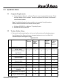
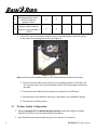
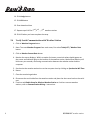
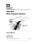
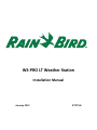
 WS‐PRO LT Weather Station Installation Manual January 2012
GT27146
WSPRO LT Table of Contents 1.0 Installation ................................................................................................................ 2 1.1 Power Sources ...................................................................................................................................... 2 1.2 Site Selection......................................................................................................................................... 2 1.3 Grounding ............................................................................................................................................. 3 1.4 Wireless Communication Weather Station .......................................................................................... 3 1.4.1 Transmissions Ranges ............................................................................................................ 3 1.4.2 Line‐of‐Sight ........................................................................................................................... 3 1.4.3 Testing Radio Transmissions.................................................................................................. 4 1.5 Direct Connect Weather Station ........................................................................................................... 4 2.0 Quick Start Guide ....................................................................................................... 5 2.1 Computer Requirements ...................................................................................................................... 5 2.2 Weather Station Setup ......................................................................................................................... 5 2.3 Weather Station Configuration ............................................................................................................ 6 2.3 Verify Serial Communication with Weather Station ............................................................................. 8 2.4 Radio Setup for Wireless Weather Stations.......................................................................................... 9 2.5 Communication Wiring Setup for Direct Connect Weather Stations ................................................. 11 3.0 Installation Procedure .............................................................................................. 13 4.0 Solar Panel Installation............................................................................................. 15 Appendix A – Grounding Recommendations................................................................... 16 A.1.0 Grounding System Installation ........................................................................................................ 16 A.1.1 Ground Resistance............................................................................................................... 16 A.1.2 Installation Requirement..................................................................................................... 16 A.1.3 ground Rod Stacking............................................................................................................ 17 A.2 Grounding System Designs ................................................................................................................. 18 A.2.1 Design “Y” ............................................................................................................................ 18 A.2.2 Design “Y” (Alternate).......................................................................................................... 19 A.2.3 Grounding Plate Design ....................................................................................................... 20 WS-PRO LT weather station
1
1.0 Installation This manual covers the procedure for installing your WS PRO LT weather station, for both direct connect and wireless communication and for solar and DC powered options. Before installing the weather station(s) at your site, read over the discussions of power sources, site selection, grounding, wireless communication and direct connect weather stations. 2.1
Power Sources
Weather stations have an internal sealed rechargeable battery that must be recharged to assure continued system function. For recharging the battery, a solar panel or a user supplied external DC power source that has a nominal rating of 18 V at 1 amp output is required. 2.2
Site Selction
The ideal site is representative of the general area, is level, and well away from obstructions such as buildings, trees, and steep slopes. If obstructions exist, use the Ten Times the Height Rule, which is illustrated in Figure 1. 2
FIGURE 1 Ten Times the Height Rule. WS-PRO LT weather station
For example, if the height of the tree T is 8 feet and the height of the shed H is 7 feet, install the weather station at least 80 ft away from the tree (e.g., 10T = 10x8 =80 ft) and 70 ft away from the shed (e.g., 10H =10x7 = 70 ft). Do not place the weather station near a sprinkler where it is likely to be sprayed by water, as this will change the rain reported by weather station. Note: If your weather station will be inside a fence to discourage vandalism, the fence top must be lower than the wind sensors even if the fence is chain‐link. 2.3
Grounding
Outdoor cables may be subject to induced currents due to lightning or other environmental factors. Therefore, proper grounding is imperative to avoid damage to the weather station and/or the Host computer. Please see Appendix A for grounding recommendations. 2.4
Wireless Communication Weather Station
1.4.1 Transmissions Ranges Wireless communication weather stations are available for installations within several ranges. Typical transmission ranges are listed below: • Up to ½ mile (0.8 km ) for the weather station 916MHz and weather station 922MHz • Up to 1/4 mile (0.4 km) for the weather station 2.40GHz of the central control computer. •
Up to 7 miles if an optional higher gain antenna is installed on both the weather station and the RFXXX Base Station 1.4.2 Line‐of‐Sight This range assumes no obstructions are in the line‐of‐sight. Line‐of‐sight is defined as a straight path between a transmitting and receiving antenna that is unobstructed by intermediate topography or obstructions. A clear line‐of‐sight is required to achieve the optimum transmission range. The affect of obstructions on the transmission range can vary. Therefore, if obstructions lie within the line‐of‐sight, you should test your radio transmissions before permanently installing your weather station. WS-PRO LT weather station
3
FIGURE 2 Line‐of‐sight examples. As the dotted line indicates, Station 1 has a clear line‐of‐sight with the Computer Site. The mountain obstructs Station 2’s line‐of‐sight and would reduce or possibly prevent wireless communications. Wireless weather stations are equipped with spread spectrum radios and include a second spread spectrum radio that is installed at the central control computer. 1.4.3 Testing Radio Transmissions To test the radio transmission of your weather station carry the weather station to the site then attempt to communicate with the central control computer. If obstructions in the line of sight are preventing the weather station from communicating, try the following: • Relocate your weather station away from obstructions • Remove the obstructions • Mount the computer base station antenna outside of the building by running the antenna cable through a window or cable run • Use a higher gain antenna (optional) at the weather station site • Install a higher gain antenna (optional) on the roof of the computer base station building and align it above the obstructions. 2.5
Direct Connect Weather Station
Direct connect weather stations are available for installations that require the weather station be placed more than a ½ mile line of sight from the central control computer. With the use of short haul modems, the weather station can be installed up to 2.4 miles away using a 24 AWG cable. Note: DCE / DTE switches on the modems are set to DCE at the central control computer and DTE at the weather station. 4
WS-PRO LT weather station
2.0 Quick Start Guide 2.1
Computer Requirements
•
Cirrus, Nimbus II, Stratus II, or Stratus LT central control system with Automatic ET and Multiple Weather Station modules. Modules are optional with Nimbus II and Stratus II central control systems. Note: The Multiple Weather Stations module is only required if multiple weather stations will be connected to one central control system. •
•
2.2
Windows 98/2000/XP, or Windows 7 Operating System Available Serial Port/COM Port Weather Station Setup
1. Remove the top foam packing from the box and verify you have all ordered equipment (see Equipment List). Report missing or damaged equipment to your local Rain Bird distributor before installing your system. Equipment List Models Direct Connect Direct Connect Solar Powered Wireless Wireless Solar Powered Wireless 2.4 GHz Solar Powered 1. WS PRO LT Weather Station
X X X X X 2. RS‐232, serial communications cable (9‐ pin to 9‐pin) X X X X X 3. Two keys X X X X X 4. RF 401‐series Spread Spectrum Radio X X X X X X X X X X X X 5. 6. 7. 8. 9. RF416‐series Spread Spectrum Radio Antenna RFXXX AC Adapter Solar Panel Solar Panel Mounting Hardware X (whip)
X X 10. RAD Modem for computer X X 11. RAD modem (in white box) for weather station X X WS-PRO LT weather station
5
12. 13. Cable for connection between weather station and RAD modem at weather station Cable for connection between RAD modem at weather station and MSP‐1 (9720) X X X X 2. Use the lift straps to remove the weather station, since removing the station by lifting on the sensors may damage the sensors (see Figure 3) FIGURE 3 Lift Straps Note: Avoid resting the weather station on the wind speed and wind direction sensors 3. Connect the serial cable (male connector) to the weather station’s RS‐232 port. Be sure to remove dust cover from the weather station RS‐232 port before connecting the cable. 4. Connect the serial cable (female connector) to computer serial COM port 5. Connect power to the weather station (e.g. solar power, user supplied DC power) 6. Turn the key to the ON position. 2.3
Weather Station Configuration
1. Request Automatic ET and Multiple Weather Stations module key codes from Global Service Plan (GSP) or from your local Rain Bird distributor. 2. Start Rain Bird central control software (e.g. Cirrus, Nimbus II or Stratus II) 6
WS-PRO LT weather station
3. Enter your key code by clicking on the Software Modules Options button and entering the key code(s) in the corresponding box (see Figure 4) FIGURE 4 Key code Dialog Box 4. Click Apply button 5. Click Close button 6. Click on Today’s ET / Weather Data button 7. Click on Weather Station Configuration button 8. Select weather station from drop down menu (see Figure 5) FIGURE 5 Weather Station Configurations 9. Select Station Type Rain Bird Turf‐CR200 10. Enter latitude and elevation where weather station will be installed 11. Assign port by clicking on Test and Set Port (see Figure 6) Figure 6 Test and Set Port 12. Select weather station 13. Select COM Port (assign to available COM port) WS-PRO LT weather station
7
14. Click Assign button 15. Click OK button 16. Enter download time 17. Repeat steps 8‐16 for 2nd, 3rd, …, 5th weather stations 18. Click OK when you have complete the setup 2.4
Verify Serial Communication with Weather Station
1. Click on Weather Program button 2. Note: To access Weather Program from main menu, first select Today’s ET / Weather Data button 3. Click on Monitor Current Data button 4. Monitor the sensor displays. Within a couple of minutes, numerical values should appear on the screen and indicator lights on the bottom of the weather station, labeled Scan/Receive, will blink every ten seconds, confirming communication between the weather station and the computer. 5. Synchronize the weather station time to the computer time by clicking on Synchronize WS Time 6. button 7. Close the monitoring window 8. Disconnect the serial cable from the weather station and place the dust cover back on the serial port. 9. Continue with Radio Setup for Wireless Weather Station or for direct connect weather stations, refer to Communication Wiring… instructions. 8
WS-PRO LT weather station
2.5
Radio Setup for Wireless Weather Station
1. Attach antenna to the radio connector labeled Antenna FIGURE 7 The radio antenna may be a surface mount antenna (left), a whipantenna(right) that connects directly to the radio, or other optional antennas (not shown). FIGURE 8 The connector marked Antenna on an RFXXX‐series radio is where the antennas attach. 2. Connect the serial cable male connector to the radio connector labeled RS‐232 WS-PRO LT weather station
9
FIGURE 9 Radio connections. The serial cable (left) connects to the port marked RS232 and the AC adapter connects to the port marked DC PWR input. 3. Connect the serial cable female connector to a computer serial COM port 4. Plug the RF401 AC adapter to the RF401 connector labeled DC PWR input 5. Plug the other end of the RF401 AC adapter into a grounded AC wall outlet. The red PWR/Tx status light should illuminate 6. Click on Weather Program button Note: To access Weather Program from main menu, first select Today’s ET / Weather Data button 7. Click on Monitor Current Data button 8. Monitor the sensor displays. Within a couple of minutes, numerical values should appear on the screen and indicator lights on the bottom of the weather station, labeled Scan/Receive, will blink every ten seconds, confirming communication between the weather station and the computer. 9. If the radio is not communicating properly, you may be experiencing interference from nearby equipment such as wireless phones, other spread spectrum radios, or another weather station. Change the location of the weather station. 10
10. If your radio is working properly, close the weather software and turn the key to the off position. You are now ready to install your weather station at a site within ½ mile from the central computer. WS-PRO LT weather station
2.6
Communication Wiring Setup for Direct Connect Weather Stations
1. Furnish and install a Belden #9883 Direct Burial Type, communication cable between the weather station and the central control computer (not to exceed 20,000 ft. / 3.8 miles with the specified 20 AWG Belden #9883 cable). Note: The Belden cable should consist of three (3) twisted pairs of wires (20 gauge), a bare copper drain wire and an aluminum shield. The three (3) twisted pairs shall be color coded as follows: one (1) black and green pair, one (1) black and red pair, and one (1) black and white pair. The black and white pair shall not be used, but kept as a spare pair. At the weather station… 2. Connect the Black (‐xmt) and Green (+xmt) pair of wires (of the communication cable) to the Black and Red wires respectively on the “Field” end of the first MSP‐1. 3. Connect the Black and Red wires on the “Equipment” end of the first MSP‐1 to the White (‐xmt) and Green (+xmt) wires of the cable (9720) furnished with the weather station. 4. Connect the Red (+rcv) and Black (‐rcv) pair of wires (of the communication cable) to the Red and Black wires respectively on the “Field” end of the second MSP‐1. 5. Connect the Red and Black wires on the “Equipment” end of the second MSP‐1 to the Red (+rcv) and Black (‐rcv) wires of the cable (9720) furnished with the weather station. Communication Wire from Central Communication Wire at Weather Station Black (‐xmt) Black Green (+xmt) Red Red (+rcv) Red Black (‐rcv) Black FIELD FIELD MSP‐1 MSP‐1 EQUIP EQUIP Black White(‐xmt) Red Green(+xmt) Red Red (+rcv) Black Black (‐rcv) FIGURE 10 Communication wiring at weather station WS PRO LT weather station
11
6. Ground the bare copper drain wire of the Belden cable along with the green ground wires of both MSP‐1 surge pipes to the grounding rod using a brass ground wire clamp. Note: Do not ground the drain wire at the central end of the cable. Leave it unused. 7. Leave the Black and White pair of wires as spares 8. Connect the other end of the cable (9720) to the Computer connection on the white box (containing RAD modem). 9. Connect the RS232 end of the second cable (9721) to the RS232 port of the weather station. 10. Connect the other end of the cable (9721) to the WX Station connection on the white box. 11. Install the white box just below the weather station using furnished U bolt. At the computer… 12. Furnish and install a Belden #9883 or equivalent, direct burial type, communication cable between the RAD modem installed near the central control computer and the access box at the central valve box location. Specifications of this cable are listed earlier in section 2.5. 13. Connect the BLACK (‐XMT) & GREEN (+XMT) pair of the Belden #9883 cable coming from the weather station to the BLACK & RED wires respectively, at the “FIELD” end of one of the MSP‐1 surge arrestors. The BLACK (‐XMT) & GREEN (+XMT) wires of the Belden #9883 communication cable going to the RAD modem installed near the central computer shall be connected to the BLACK & RED wires respectively, at the “EQUIPMENT” end of the same MSP‐1 surge arrestor. 14. The RED (+RCV) & BLACK (‐RCV) pair of the Belden #9883 cable coming from the weather station shall be connected to the RED & BLACK wires respectively, at the “FIELD” end of the other MSP‐1 surge arrestor. The RED (+RCV) & BLACK (‐RCV) wires of the Belden #9883 communication cable going to the RAD modem shall be connected to the RED & BLACK wires respectively, at the “EQUIPMENT” end of the same MSP‐1 surge arrestor. 15. Connect the black (‐xmt) wire to the (‐xmt) port of the Rad modem furnished with the weather station kit. Use a small screw driver to open the hole, insert the wire and then tighten with the screw driver. 16. Continue with the green (+xmt), red (+rcv) and black (‐rcv) wires respectively. 17. Connect the RAD modem to a COM port on your computer (it might be necessary to use a 9 to 25 pin connector). 12
WS-PRO LT weather station
Installation Procedure 3.0
1. Mount a mast/pole 1.25” OD and 8 to 10 feet (312 cm) high on cement base. 2. Place your weather station assembly on top of the mast/pole with the base firmly seated on the top edge of the mast/pole of (see Figure 11) FIGURE 11 Installation at Pole 3. Loosely tighten the U‐bolt nuts so that the weather station is stable but can be rotated on the mast/pole. FIGURE 12 U‐Bolt Nuts 4. As a reference, use a compass and rotate the weather station assembly until the reference line on the wind direction sensor is aligned with the Magnetic North (see Figure 13). WS PRO LT weather station
13
N N FIGURE 13 Wind Direction Alignment 5. Firmly tighten the U‐Bolt nuts 6. Confirm the weather station is level by viewing the bull’s level on top of the weather station (see Figure 14). Minor adjustments can be made by placing shims between the weather station base and the top of the pole. Bull’s level FIGURE 14 Bull's Level on top of the weather station 7. Connect the power source that will recharge the internal sealed rechargeable battery. For Solar Powered weather stations follow instructions below. 8. Remove the red cap from the solar radiation sensor (Figure 15). FIGURE 15 Solar Radiation Sensor
9. Properly ground the weather station by connecting a #10 gauge or larger wire to the earth ground lug located on the base of the weather station. Refer Appendix A for grounding recommendations. 10. Refer to section 2.5 Communication Wiring for direct connect weather stations. 14
WS-PRO LT weather station
11. Turn the key to the ON position and return to the computer site to confirm the weather station is working properly. 4.0 Solar Panel Installation The solar panel recharges the weather station internal battery. It has a 72 sq. inch surface area and produces 5 watts, at a peak of 17.1 volts. FIGURE 16 5W Solar Panel 1. Place the solar panel on the mast below the station to the maximum distance allowed by the solar panel cable. 2. Loosely tighten the U‐bolt so that the solar panel is stable but can be rotated on the mast or pole. 3. Use a compass to properly align the solar panel. If your site is in the northern hemisphere, the glass surface of the panel should face south. If your site is in the southern hemisphere, the glass surface of the panel should face north. 4. Connect the cable to the weather station connector labeled Solar Panel 5. Tighten the thumb screw and the U‐bolt WS PRO LT weather station
15
Appendix A – Grounding Recommendations A.1
Grounding System Installation
To prevent lightning damage to your equipment, Rain Bird recommends installing a grounding system for the equipment (including controllers, weather stations, and central control systems). The grounding system discharges lightning‐induced electrical current into the earth rather than allow the surge to pass through power wires or field wires to your equipment’s electronic components. A.1.1 Ground Resistance Ground resistance occurs when grounding system components, or the soil itself, oppose the flow of electricity into the earth. Ground resistance is measured in units called “ohms” (Ω). The higher the ground resistance (higher ohm readings), the less chance the surge will be shunted to ground rather than to the equipment’s electronic components. Figure A.1‐1 shows points where grounding systems can develop resistance. To decrease ground resistance, Rain Bird recommends irrigating the soil around the grounding system. Each grounding system should have a dedicated irrigation zone with sprinkler heads and its own watering program to maintain soil moisture around the grounding system. A properly installed grounding system should maintain a maximum ground resistance of 10 ohms, or less. If you are unable to reach a resistance of 10 ohms or less, you can decrease resistance by surrounding the grounding rods or plates with ground enhancement material, such as POWER SET from Paige Electric Corporation (P/N 1820058), or GEM from ERICO (P/N GEM‐25A). If ground resistance still measures higher than 10 ohms, you can extend the ground rod length as described in “Ground Rod Stacking,” or use additional grounding rods, as shown in grounding system design “Y” (Alternate). A.1.2 Installation Requirement The following requirements apply to all grounding system designs (design Y and the “Grounding Plate” design). All grounding rods or plates must be connected together below grade with #6 AWG or larger solid bare copper wire. Install the connecting wire in as straight a line as possible. If you must make a turn or bend in the wire, make the turn in a sweeping curve with a minimum radius of eight inches and a minimum included angle of 90o. 16
WS-PRO LT weather station
To minimize resistance, the copper wire must be pre‐welded to the grounding rods/plates, or welded to the rods/plates using an exothermic welding process at the site. Make sure all welds are secure before burying the grounding rods. Rods and plates with welded joints do not need periodic visual inspection and can be fully buried (no valve box required). Measure the ground resistance around the grounding system after installation, and once every year after that. Note: The ground wire from the equipment to the grounding system should be as short as possible and have no bends, kinks, or coils in the wire. Inspect the grounding system’s clamped connections to the equipment (not the welded grounding system connections) once a year to make sure they are secure and corrosion‐
free. FIGURE A.1‐1 Grounding systems can develop resistance at many points\ A.1.3 Ground Rod Stacking Threaded couplers (shown in Figure A.1‐2) are ground rod splices. If a single grounding rod fails to produce 10‐ohm ground resistance (maximum), threaded couplers can be used to “stack” grounding rods. Note: Use threaded couplers made of the same material as your grounding rods. Stacking ground rods increases the total effective rod length, decreasing ground resistance. Joining the rods together with threaded couplers forms a secure connection so the grounding rods can be assembled quickly and easily. WS PRO LT weather station
17
FIGURE A.1‐2 Stacking groundings rods with threaded couplers can help decrease ground resistance A.2
Grounding System Designs
A.2.1 Design “Y” Design “Y” Design “Y” (shown in Figures A.2‐1 and A.2‐2) consists of three, 5/8” ‐diameter x 8‐ foot‐long, copper‐clad grounding rods. Install the rods in a radial 1200 star (“Y”) configuration. Each rod must be installed in a true vertical position, at least 16 feet from the equipment Note: All grounding system diagrams are not to exact scale FIGURE A.2‐1 Design “Y” uses three groundings rods imnstalled in radial 120 degress “Y‐shaped” configuration 18
WS-PRO LT weather station
FIGURE A.2‐2 Grounding system “Y can be installed as shown, or with ground enchancement material to reduce ground resistance even further. A.2.2 Design “Y” (Alternate) An alternate design “Y” (shown in Figures A.2‐3 and A.2‐4) uses three radials in a 120 degree star (“Y”) arrangement. Each radial consists of three, 5/8”‐diameter x 8‐foot long copper‐clad grounding rods. The first rod in each radial must be at least eight feet from the equipment. The rest of the rods must be at least 16 feet from any other rod. FIGURE A.2‐3 Desing “Y”(Altrenate) uses nine copper‐clad grounding rods installed in a 120 degree star configuration WS PRO LT weather station
19
FIGURE A.2.‐4 The alternate version of grounding design “Y” uses nine grounding rods to reduce ground resistance A.2.3 Grounding Plate Design The “Grounding Plate” design (shown in Figures A.2‐5 and A.2‐6) consists of one vertical 8‐foot copper‐clad grounding rod at least eight feet from the equipment, and a copper grounding plate (minimum dimensions 4”x96”x.0625”). Install the grounding plate horizontally, three feet deep and 15 feet from the grounding rod. FIGURE A.2‐5 The” Grounding Plate” design uses one copper‐clad grounding rod and a rectangular copper grounding plate. 20
WS-PRO LT weather station
FIGURE A.2‐6 The “Grounding Plate” design may be used with or without ground enhancement material, depending on side conditions. WS PRO LT weather station
21